EP1473982A2 - Cooling device - Google Patents
Cooling device Download PDFInfo
- Publication number
- EP1473982A2 EP1473982A2 EP04251406A EP04251406A EP1473982A2 EP 1473982 A2 EP1473982 A2 EP 1473982A2 EP 04251406 A EP04251406 A EP 04251406A EP 04251406 A EP04251406 A EP 04251406A EP 1473982 A2 EP1473982 A2 EP 1473982A2
- Authority
- EP
- European Patent Office
- Prior art keywords
- heat
- cooling device
- vanes
- fan
- mass
- Prior art date
- Legal status (The legal status is an assumption and is not a legal conclusion. Google has not performed a legal analysis and makes no representation as to the accuracy of the status listed.)
- Withdrawn
Links
Images








Classifications
-
- H—ELECTRICITY
- H10—SEMICONDUCTOR DEVICES; ELECTRIC SOLID-STATE DEVICES NOT OTHERWISE PROVIDED FOR
- H10W—GENERIC PACKAGES, INTERCONNECTIONS, CONNECTORS OR OTHER CONSTRUCTIONAL DETAILS OF DEVICES COVERED BY CLASS H10
- H10W40/00—Arrangements for thermal protection or thermal control
- H10W40/40—Arrangements for thermal protection or thermal control involving heat exchange by flowing fluids
- H10W40/43—Arrangements for thermal protection or thermal control involving heat exchange by flowing fluids by flowing gases, e.g. forced air cooling
-
- F—MECHANICAL ENGINEERING; LIGHTING; HEATING; WEAPONS; BLASTING
- F28—HEAT EXCHANGE IN GENERAL
- F28F—DETAILS OF HEAT-EXCHANGE AND HEAT-TRANSFER APPARATUS, OF GENERAL APPLICATION
- F28F3/00—Plate-like or laminated elements; Assemblies of plate-like or laminated elements
- F28F3/02—Elements or assemblies thereof with means for increasing heat-transfer area, e.g. with fins, with recesses, with corrugations
-
- H—ELECTRICITY
- H10—SEMICONDUCTOR DEVICES; ELECTRIC SOLID-STATE DEVICES NOT OTHERWISE PROVIDED FOR
- H10W—GENERIC PACKAGES, INTERCONNECTIONS, CONNECTORS OR OTHER CONSTRUCTIONAL DETAILS OF DEVICES COVERED BY CLASS H10
- H10W40/00—Arrangements for thermal protection or thermal control
- H10W40/20—Arrangements for cooling
- H10W40/22—Arrangements for cooling characterised by their shape, e.g. having conical or cylindrical projections
- H10W40/226—Arrangements for cooling characterised by their shape, e.g. having conical or cylindrical projections characterised by projecting parts, e.g. fins to increase surface area
Definitions
- the present invention relates generally to a cooling device including a heat spreader for removing heat from a component connected with the cooling device, preferably to a cooling device that includes a heat spreader made from a dissimilar material with a higher thermal conductivity than a material of a heat mass of the cooling device so that heat in a component connected with the cooling device is efficiently removed.
- Heat sink devices have become commonplace as a means for dissipating waste heat from electronic devices such as the types described above.
- a component to be cooled is carried by a connector that is mounted on a PC board.
- a heat sink is mounted on the component by attaching the heat sink to the connector using a clip or fasteners, for example.
- the heat sink is mounted to a PC board that carries the electronic device and fasteners or the like are used to connect the heat sink to the PC board via holes that are drilled in the PC board.
- the need to drill holes can be one disadvantage to using fasteners because the fasteners or other mounting hardware used for connecting the heat sink to the PC board are usually electrically conductive and there is a risk of an electrical short due to contact between a PC board trace and the mounting hardware. Moreover, to avoid electrical shorts, the PC board traces can be routed around the hole, but that routing requires keep out zones that can complicate the routing of the traces.
- a heat sink used in conjunction with a modern high clock speed electronic device will use an electrical fan mounted on top of the heat sink or within a cavity formed by cooling fins/vanes of the heat sink.
- the cooling fins increase the surface area of the heat sink and maximize heat transfer from the heat sink to ambient air that surrounds the heat sink.
- the fan causes air to circulate over and around the cooling fins thereby transferring heat from the cooling fins into the ambient air.
- a tall heat sink will require additional vertical clearance between the heat sink and a chassis the heat sink is contained in to allow for adequate air flow into or out of the fan.
- the heat sinks size is increased in a horizontal direction, then the amount of area available on the PC board for mounting other electronic devices is limited.
- the heat sink has a cylindrical shape formed by the fins it is often not possible to mount several such heat sinks in close proximity to each other because air flow into and out of the fins is blocked by adjacent heat sinks with a resulting decrease in cooling efficiency.
- a depth of the fins could extend all the way to a center of the heat mass; however, the depth and surface area of the fins is reduced by a diameter of the fan because the fan is mounted in a cavity having a diameter that is slightly larger than the fans diameter to provide clearance for the fan blades. Consequently, the heat mass of the heat sink must be made broader to compensate for the reduced surface area of the fins. The broader heat mass increases the size, cost, and weight of the heat sink.
- the reduced depth of the fins makes it easier for the fins to be bent if damaged.
- One possible consequence of a bent fin is that it will contact and damage the fan blades and/or cause the fan to stall thereby damaging the fan or causing the fan to fail.
- the fan is mounted in the cavity formed by the fins, power leads for the fan must be routed through a space between the fins. Sharp edges on the fins can cut the power leads or cause an electrical short. In either case, the result is that the fan will fail.
- glue is typically used to mount the fan to the heat sink and the glue can get into the fan and cause the fan to fail. Any of the above mentioned fan failure modes can lead to a failure of the electronic device the heat sink was designed to cool because air circulation generated by the fan is essential to effectively dissipate waste heat from the electronic device.
- Some prior heat sinks attempt to overcome the aforementioned disadvantages of a larger heat mass or increased fin area by using a metal heat spreader that is joined with the heat sink.
- Typical processes for joining the heat spreader with the heat sink include brazing, soldering, heat shrink fitting, vacuum brazing, micro forging and shrink fitting.
- the present invention seeks to provide an improved cooling device.
- the preferred embodiment can provide a cooling device with a heat spreader that allows for the use of dissimilar materials that are optimized for efficient thermal conduction and heat dissipation. It can also provide a cooling device with a heat spreader that eliminates micro gaps between the heat spreader and a heat mass so that there is a low thermal resistance between the heat spreader and the cooling device.
- the cooling device may have a heat spreader that provides an inexpensive processes for joining the heat spreader with the cooling device.
- the cooling device may have dissimilar materials for the heat mass and the heat spreader allowing the heat spreader to be fixedly connected with the heat mass to prevent the heat mass and the heat spreader from separating from each other.
- the cooling device is provided with a heat spreader that allows for easy disassembly and in field servicing.
- the preferred embodiment provides a cooling device for dissipating waste heat from a component to be cooled.
- the cooling device includes a heat mass made from a first material and including a base, an arcuate boss that is surrounded by an arcuate groove, a taper bore extending from the base to the boss, and an aperture extending from the boss to the taper bore.
- a fastener including a head and a threaded shaft is inserted through the aperture with the head in contact with the boss.
- a heat spreader made from a second material that is dissimilar to the first material includes a taper wall that complements the taper bore of the heat mass, a mounting surface adapted to thermally connect with the component, a threaded aperture adapted to receive the threaded shaft of the fastener.
- a thermal sealant is connected with the taper wall and/or the taper bore.
- the heat spreader is inserted into the taper bore and the threaded shaft is threaded into the threaded aperture and the head of the fastener is turned to urge the taper wall into contact with the taper bore.
- the optional thermal sealant is operative to seal micro gaps between the taper bore and the taper wall so that a thermal resistance between the heat mass and the heat spreader is reduced.
- Extending from the heat mass are a plurality of vanes that are spaced apart from each other to define a primary slot between adjacent vanes and extending to the heat mass.
- the vanes have a surface area that increases in a radially outward direction from an axis of the heat mass and a portion of the surface area of the vanes also increase in a direction that is along the axis.
- the vanes include a top face upon which a fan can be mounted, an aerodynamically profiled inner wall that defines a chamber that surrounds the boss and the groove, and an outer wall including a surface profile that widens from the base to the top face and includes a smooth curved portion, a draft portion, and a smooth radially outward portion.
- the surface area of the vanes is increased by a plurality of fins formed in each vane by a secondary slot extending through a portion of the vane.
- An air flow chamber may create a three-dimensional air flow that dissipates heat from the cooling device.
- the air flow exits through the vanes and a portion of the fins in an exhaust flow that dissipates heat from the vanes and the fins.
- the exhaust flow creates a low pressure region within the chamber that induces an intake flow into the chamber through a major portion of the fins and a top portion of the vanes thereby dissipating heat from the fins and the vanes.
- the low pressure region induces a surface flow along the inner wall so that the surface flow wets the groove and the boss as it passes over the groove and the boss to dissipate heat from the heat mass.
- the preferred cooling device can solve the aforementioned disadvantages of prior heat sinks.
- the cooling device can be mounted to a component to be cooled by using a clip to connect the cooling device with a connector that carries the component. Therefore, holes need not be drilled in a PC board to mount the cooling device.
- the cooling device may employ vanes that extend deep within the heat mass and the surface area of the vanes increases from a bottom of the cooling device to a top of the cooling device and in a radially putward direction from the heat mass. Furthermore, each vane is split into at least two fins thus further increasing the surface area available for cooling. As a result, the cooling device need not be made taller to increase vane surface area and the cooling device need not be made wider to increase the size of the heat mass.
- the top of the cooling device may be adapted to mount a fan so that the heat mass is not blocked by the fan and air can circulate over the heat mass thus further dissipating heat from the cooling device.
- the fan can include a shroud that surrounds the blades unlike the fans that are mounted in a cavity formed by fins of prior heat sink devices.
- the cooling device can also mount a fan without a shroud using a clip or space frame to mount the fan to the top of the cooling device. Because the fan is mounted on top of the cooling device, the wires of the power leads for the fan are not routed through the vanes or fins thereby eliminating the risk of the wires being cut or short circuited.
- the shape of the cooling device (wider at the top than at the bottom) allows for several of the cooling devices to be placed adjacent to each other without blocking air flow into and out of the vanes and fins.
- the vanes of the cooling device can be tangentially oriented with a circle centered on an axis of the heat mass and the vanes can be inclined at an angle with respect to the axis such that the angle of inclination substantially matches or closely approximates a pitch angle of the blades of a fan.
- the tangential orientation and the inclination of the vanes reduces fan noise due to air shock losses.
- the heat spreader can be mounted with the heat mass using a fastener or the like thereby eliminating the problems and costs associated with the prior welding or brazing of dissimilar metals to each other. Additionally, the use of the fastener allows for easy in field servicing, repairs, and upgrades to the cooling device. Furthermore, if necessary, the heat spreader can be fixedly connected with the heat mass by preventing removal of the fastener and/or by welding, brazing, soldering the heat spreader to the heat mass.
- a second material for the heat spreader can be selected for its superior thermal conductivity properties for efficient conduction and dissipation of waste heat from the component connected with the mounting surface of the heat spreader.
- the optional thermal sealant of the present invention solves the aforementioned problems caused by micro gaps between prior heat spreaders and heat sinks by sealing those micro gaps thereby reducing a thermal resistance between the heat spreader and the heat mass.
- the described embodiments provide a cooling device for dissipating heat from a component that is in thermal communication with a heat spreader of the cooling device.
- the thermal communication can be by direct contact between the heat spreader and the component or by an intermediate material (e.g a thermal interface material) positioned between the cooling device and the component as will be described below.
- the component can be any heat source, such as an electrical component, for example.
- the cooling device includes a heat mass made from a first material and including a base, a boss surrounded by a groove with the groove and the boss symmetrically positioned about an axis of the heat mass, a taper bore extending from the base to the boss, and an aperture extending from the boss to the taper bore.
- the boss has a convex arcuate surface profile and the groove has a concave arcuate surface profile.
- a fastener including a head and a threaded shaft is inserted through the aperture with the head in contact with the boss.
- a heat spreader made from a second material that is dissimilar to the first material includes a taper wall that complements the taper bore of the heat mass, a mounting surface adapted to thermally connect with the component, and a threaded aperture adapted to receive the threaded shaft of the fastener.
- a thermal sealant that can be connected with the taper wall, the taper bore, or both the taper wall and the taper bore as will be described below.
- the heat spreader is inserted into the taper bore and the threaded shaft is threaded into the threaded aperture and the head of the fastener is turned to urge the taper wall into contact with the taper bore.
- the optional thermal sealant is operative to seal micro gaps between the taper bore and the taper wall so that a thermal resistance between the heat mass and the heat spreader is reduced.
- a plurality of vanes are in contact with the heat mass and surround the heat mass.
- the vanes are spaced apart from one another to define a primary slot between adjacent vanes that extends to the heat mass.
- the vanes have a surface area that increases in a radially outward direction from the axis and in a direction along the axis.
- a plurality of fins are formed in each vane by a secondary slot extending through a portion of each vane.
- the vanes include a top face and an aerodynamically profiled inner wall that includes a first portion extending from the groove and terminating at a second portion that extends to the top face.
- the inner wall defines a chamber that surrounds the groove.
- the vanes also include an outer wall having a surface profile that widens from the base to the top face. The surface profile includes a smooth curved portion, a draft portion, and a smooth radially outward portion.
- An air flow entering the chamber creates a three-dimensional air flow that dissipates heat from the cooling device.
- the air flow exits the primary slots and a bottom portion of the secondary slots in an exhaust flow that dissipates heat from the vanes and the fins.
- the exhaust flow creates a low pressure region within the chamber that induces an intake flow into the chamber through a major portion of the secondary slots and a top portion of the primary slots thereby dissipating heat from the fins and the vanes.
- the low pressure region induces a surface flow along the first and second portions of the inner wall so that the surface flow wets the groove and the boss as it passes over the groove and the boss to dissipate heat from the heat mass.
- the heat spreader is operative to increase a thermal conductivity of the cooling device by effectively spreading waste heat from the component to a larger surface area on the heat mass to reduce a heat concentration at an interface between the heat spreader and the heat mass.
- the second material of the heat spreader is dissimilar to the first material of the heat mass and is selected based on properties for superior heat conduction and heat dissipation as compared with similar properties for the first material of the heat mass.
- the second material of the heat spreader makes the heat spreader a better thermal conductor than the heat mass, the waste heat from the component is conducted through the heat spreader and is then transferred to the heat mass.
- the contact area between the taper bore of the heat mass and the taper walls of the heat spreader is greater than the aforementioned thermal contact area of 900.0 mm 2 at the mounting surface. Therefore, the heat is spread out over a larger surface area and heat concentration per unit of area is reduced when compared to the heat concentration at the thermal contact area.
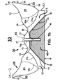
- a cooling device 10 for dissipating heat from a component includes a heat mass 11, a boss 13, and a groove 15 that completely surrounds the boss 13.
- the boss 13 and the groove 15 are symmetrically positioned about an axis Z-Z of the heat mass 11.
- the boss 13 has a convex arcuate surface profile and the groove 15 has a concave arcuate surface profile.
- the arcuate profiles of the boss and the groove ( 13, 15 ) blend into each other as illustrated by a dashed line a .
- the cooling device 10 further includes a base 17.
- the heat mass 11 also includes a tape bore 14 extending from the base 17 to the boss 13 and an aperture 14a extending from the boss 13 to the taper bore 14.
- the aperture 14a is a through hole that is adapted to receive a shaft of a fastener (see FIG. 1 b ) as will be described below.
- the heat mass 11 is made from a first material.
- a thermal sealant can be applied to the taper bore 14 as depicted by dashed arrows 44.
- the cooling device 10 includes a heat spreader 40 that includes a mounting surface 19 adapted to thermally conhect the heat spreader 40 with the component (not shown), a taper wall 41 having a profile (see reference numeral 41p in FIGS. 7a and 7b ) that complements the taper bore 14 of the heat mass 11, and a threaded aperture 43.
- a fastener 45 including a head 47 and a threaded shaft 49 is inserted through the aperture 14a with the head 47 in contact with the boss 13.
- the threaded shaft 49 is threaded into the threaded aperture 43 and the head 47 is turned (e.g. using a wrench, nut driver, Allen wrench, hex driver, TORX® driver, etc.) to thread the fastener 45 into the heat spreader 40 thereby urging the taper wall 41 into contact with the taper bore 14.
- the heat spreader 40 is made from a second material that is dissimilar to the first material of the heat mass 11.
- the heat spreader 40 must be a better thermal conductor than the heat mass 11. Accordingly, the dissimilarity between the first and second materials can be accomplished using different materials for the heat mass 11 and the heat spreader 40 or by using different alloys of the same material (e.g. copper ( Cu ) for the heat mass 11 and a copper alloy for the heat spreader 40 ) for the heat mass 11 and the heat spreader 40.
- copper ( Cu ) for the heat mass 11 and a copper alloy for the heat spreader 40
- aluminum ( Al ) or an aluminum alloy can be used for the heat mass 11 and copper ( Cu ) or a copper alloy for the heat spreader 40.
- the first material for the heat mass 11 can be a material including but not limited to aluminum ( AI ), an aluminum alloy, copper ( Cu ), a copper alloy, and a ceramic material.
- the second material for the heat spreader 40 can be a material including but not limited to copper ( Cu ), a copper alloy, silver ( Ag ), a silver alloy, silicon ( Si ), gold ( Ag ), graphite, a carbon fiber material, a carbon fiber reinforced material, and a gold alloy.
- the fastener 45 should be made from a high tensile strength material so that a pulling load resulting from the tightening of the head 47 will not damage the fastener 45 or the threaded shaft 49 .
- the material for the fastener 45 it is preferable for the material for the fastener 45 to be rust resistant.
- a stainless steel material can be used to accomplish the tensile strength requirement and the rust resistance requirement.
- the head 47 includes either an Allen key slot or a Hex/Square head slot in order to withstand an assembly torque required to tighten the fastener 45.
- the torque required to adequately tighten the fastener 45 will be application and material dependent; however, the torque can be in a range including but not limited to 6.0 Ibs-inch to about 500.0 Ibs-inch.
- the fastener 45 may be desirable to prevent the fastener 45 from being removed after it has been tightened. For instance, to prevent loosening of the fastener 45 which could result in a higher thermal resistance between the taper wall 41 of the heat spreader 40 and the taper bore 14 of the heat mass 11 because the taper wall 41 is no longer urged into firm thermal contact with the taper bore 14.
- the fastener 45 can have a sealant/adhesive such as LOCTITE® applied to the threaded shaft 49 prior to insertion and tightening. Consequently, after the sealant/adhesive has set, the fastener 45 is fixedly connected with the heat mass 11, the heat spreader 40 , or both the heat mass 11 and the heat spreader 40.
- the fastener 45 can be fixedly connected using a process including but not limited to welding, friction stir welding, soldering, or brazing to the head 47 to the boss 13 of the heat mass 11, for example.
- a seam S between the head 47 and the boss 13 can be welded, soldered, or brazed to fixedly connect the heat spreader 40 to the heat mass 11 and/or to prevent removal of the fastener 45 .
- a spring or lock washer can be used to secure the fastener 45 thereby preventing removal.
- the material for the fastener 45 can be selected to be identical to the second material or it can be an alloy of the second material so that a thermal mass of the heat spreader 40 is increased and a contact area between the heat spreader 40 and the heat mass 11 is also increased due the fastener 45 being in thermal contact with the threaded aperture 43 , the aperture 14a, and the boss 13.
- a thermal sealant can be applied to the head 47 and/or the threaded shaft 49 to seal micro voids and to reduce thermal resistance between the fastener 45 , the heat mass 11 and the heat spreader 40.
- the heat spreader 40 is fixedly connected with the heat mass 11 using a process including but not limited to brazing, soldering, friction stir welding (FSW), or welding a portion of the heat spreader 40 to the heat mass 11.
- a seam S between the mounting surface 19 and the base 17 can be welded, soldered, or brazed to fixedly connect the heat spreader 40 with the heat mass 11.
- Another advantage to fixedly connecting the heat spreader 40 to the heat mass 11 is that taper wall 41 and the taper bore 14 are held in thermal contact with each other thereby reducing thermal resistance.
- the fastener 45 can also be fixedly connected as described above.
- EN Plating is essential for soldering copper ( Cu ) to aluminum ( A I).
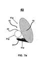
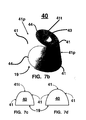
- an optional thermal sealant 44 is connected with the taper walls 41 and can cover the top and side surfaces of the taper walls 41 as depicted by the dashed circles 44 in FIGS. 7a and 7b.
- the thermal sealant 44 is connected with the taper walls 41 prior to the above step of inserting the heat spreader 40 in the taper bore 14 and tightening the fastener 45.
- the thermal sealant 44 can be connected with the taper bore 14 (see FIG. 1a ) or connected with both the taper bore 14 and the taper walls 41 . However, it may be easier to coat, deposit, or connect the thermal sealant 44 on the taper walls 41.
- Suitable materials for the thermal sealant 44 include but are not limited to a thermally conductive paste, a thermally conductive grease, silicone, paraffin, a phase transition material, graphite, a coated aluminum foil, and carbon fiber.
- the thermal sealant 44 can be screen printed, pasted, dip coated, dispensed by a tool, or applied with a brush to the taper walls 41 of the heat spreader 40, for example.
- a plurality of vanes 21 are in contact with the heat mass 11 and the vanes 21 are spaced apart from one another to define a primary slot P (see FIGS. 2a and 2c ) between adjacent vanes 21.
- the vanes 21 have a surface area that increases in a radially outward direction from the axis Z-Z as indicated by the dashed arrow r. At least a portion of the vanes 21 have a surface area that increases in a direction along the axis Z-Z as shown by dashed arrow y .
- the primary slot P extends to the heat mass 11 and the primary slot P includes a first arcuate surface profile 21a along the heat mass 11.
- the first arcuate profile 21a terminates on a plane H-H (see FIG. 1a ). It is also preferable that the vanes 21 are equidistantly spaced apart from each another. By extending the primary slot P to the heat mass 11 , air flow through the vanes 21 also wets the heat mass 11 to dissipate heat therefrom.
- the first arcuate surface profile 21 a can be an arc having a radius from about 38.0 millimeters to about 45.0 millimeters.
- the cooling device 10 is that a fan (not shown) for generating an air flow is not mounted on the heat mass 11. Consequently, the vanes 21 can extend deep into the heat mass 11 (as illustrated by arrow e ) and the depth of the vanes 21 provides a large surface area for efficient dissipation of waste heat and exposes the heat mass 11 to an air flow (see FIGS. 3a and 3b ) that wets over the boss 13 and the groove 15 so that additional waste heat can be dissipated from the heat mass 11.
- the vanes 21 also include a top face 29 , an aerodynamically profiled inner wall 26 including a first portion 25 that extends from the groove 15 and terminates at a second portion 27 that extends to the top face 29 .
- the first portion 25 blends with the arcuate profile of the groove 15 as illustrated by dashed line b and the first portion 25 blends with the second portion 27 as illustrated by dashed line C .
- the second portion 27 blends with the top face 29 as illustrated by dashed line d .
- the inner wall 26 can include additional portions and the present invention is not to be construed as being limited to the first and second portions ( 25, 27 ).
- the inner wall 26 defines a chamber 30 that surrounds the groove 15.
- the first portion 25 of the inner wall 26 is a slope surface and the second portion 27 of the inner wall 26 is a concave arcuate surface.
- the sloped and concave arcuate surfaces aerodynamically interact with an air flow into the chamber 30 so that the air flows along the first and second portions ( 25, 27 ) of the inner wall 26 and wet over the groove and the boss ( 15, 13 ) to dissipate heat from the heat mass 11 as will be described below in reference to FIGS. 3a and 3b.
- the first portion 25 can be inclined at an angle ⁇ with respect to the axis Z-Z as illustrated in FIG. 1a.
- the angle ⁇ can be in a range from about 15.0 degrees to about 75.0 degrees. If the vanes 21 have a tangential orientation with a circle about the axis Z-Z as will be discussed below in reference to FIG. 6, then the first portion 25 will have a tangential orientation with the groove 15.
- the angle ⁇ will vary based primarily on an output of a fan (not shown) in cubic feet per minute (CFM).
- the vanes 21 further include an outer wall 32 having a surface profile that widens from a bottom 11a of the heat mass 11 to the top face 29 and includes a smooth curved portion 33, a draft portion 35, and a smooth radially outward portion 37.
- the draft portion 35 an be substantially parallel to the axis Z-Z or the draft portion 35 can be inclined at an angle ⁇ .
- the vanes 21 include at least one secondary slot S that extends through a portion of each vane 21 to define a plurality of fins 23 (two are shown) in each vane 21.
- the available surface area for dissipating waste heat is increased and the secondary slot S provides an additional air flow path between the fins 23 that further increases waste heat dissipation.
- the secondary slot S extends to the heat mass 11 and the secondary slot S includes a second arcuate profile 23a (see dashed line in FIG. 1a ) along the heat mass 11.
- the second arcuate profile 23a terminates on the plane H-H.
- the second arcuate profile 23a can be an arc having a radius from about 31.0 millimeters to about 38.0 millimeters.
- Reference points for a center of the above mentioned radiuses will be positioned outside the cooling device 10 and the actual location of the center will depend on the arcs radius.
- the position of the center of the radius will be at least about 5.0 millimeters out side of the cooling device 10 to accommodate a cutting tool used in a machining process for making the cooling device 10.
- the position of the center of the radius is a limitation imposed by a machining process that uses cutting wheels to form the vanes 21 and the fins 23. If the vanes 21 and the fins 23 can be diecasted or impact forged, then the arc radius could be reduced and the position of the center of the radius could come inside the cooling device 10 .
- the cooling device 10 can be made amendable to a diecasted or impact forged process by reducing the number of vanes 21.
- FIGS. 3a and 3b heat dissipation by an air flow F entering the chamber 30 is illustrated.
- a portion of the air flow F exits the chamber 30 through the primary slots P and a bottom portion of the secondary slots S (not shown) in an exhaust flow E .
- the exhaust flow E passes over the vanes 21 and the fins 23 and dissipates heat therefrom.
- a low pressure region ⁇ P is created within the chamber 30 by the exhaust flow E. Consequently, the low pressure region ⁇ P induces an intake flow I into the chamber 30 through a major portion of the secondary slots S and a top portion of the primary slots P (not shown) thereby dissipating heat from the fins 23 and the vanes 21.
- the low pressure region ⁇ P also induces a surface flow B along the aerodynamically shaped first and second portions ( 25, 27 ) of the inner wall 26.
- the surface flow B passes over the arcuate profiles of the groove and boss ( 15, 13 ) thereby dissipating heat from the heat mass 11 as the surface flow B circulates back towards (i.e. it is a balancing air flow) the low pressure region ⁇ P. Therefore, another advantage of the cooling device 10 is that waste heat is efficiently dissipated by a three-dimensional air flow (comprising E, I, and B) through the vanes 21 and the fins 23, and passing over the groove and boss ( 15, 13 ).
- the arcuate surface profile of the boss 13 includes but is not limited to a profile of a sphere, a frustum of a sphere, a cone, and a frustum of a cone.
- the boss 13 has a conical surface profile.
- the surface profile could also be spherical.
- the boss 13 has a surface profile that is a frustum of a cone due to a substantially flat head 47 of the fastener 45 .
- the combined shape of the head 47 and the boss 13 can result in a conical surface profile.
- the boss 13 could also have a surface profile that is a frustum of a sphere.
- the arcuate surface profile of the groove 15 includes but is not limited to a semi-circular profile as illustrated in FIGS. 1a and 1b.
- the boss 13 has a diameter d B (see FIG. 1a ) that is less than a diameter of a hub 79 of a fan 70 (see FIG. 9 ).
- the groove 15 should have a radius r G (see FIG. 9 ) that provides a smooth change in air flow direction for the surface flow B as it transitions from the first portion 25 to the groove 15 so that the surface flow B flows over the groove 15 and onto the boss 13 (see FIG. 3a ).
- the boss 13 , the groove 15 , and the inner wall 26 i.e. 25 and 27
- the vanes 21 can be inclined at angle with respect to the axis Z-Z.
- the vanes 21 are inclined at an angle ⁇ measured between a line 21c and the axis Z-Z.
- the line 21c is measured along the primary slot P of the fins 23.
- the inclination of the angle ⁇ includes but is not limited to a range from about 0 (zero) degrees to about 25.0 degrees. In another embodiment of the present invention as illustrated in FIG.
- the angle at which the vanes 21 are inclined with respect to the axis Z-Z includes a first angle ⁇ 1 measured between a line 21d and the axis Z-Z and a second angle ⁇ 2 measured between a line 21e and the axis Z-Z.
- the first angle ⁇ 1 is measured along the smooth radially outward portion 37 of the fins 23.
- the inclination of the first angle ⁇ 1 includes but is not limited to a range from about 0 (zero) degrees to about 25.0 degrees.
- the second angle ⁇ 2 is measured along the smooth curved portion 33 of the fins 23.
- the inclination of the second angle ⁇ 2 includes but is not limited to a range from about 5.0 degrees to about 18.0 degrees. Because the fins 23 are defined by the vanes 21, the fins 23 and the vanes 21 are inclined at the angles ( ⁇ , ⁇ 1 , and ⁇ 2 ) as described above.
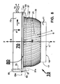
- the vanes 21 have a tangential orientation with respect to a circle C t (shown in dashed line) centered about the axis Z-Z (shown as a " + ") and having a predetermined diameter.
- a circle C t shown in dashed line
- Z-Z shown as a " + ”
- FIG. 6 an example of the tangential orientation of the vanes 21 is illustrated by a plurality of the vanes 21 having tangent lines t drawn through their primary slots P and tangentially crossing a perimeter of the circle C t .
- the predetermined diameter includes but is not limited to a range from about 3.0 millimeters to about 12.0 millimeters.
- At least a portion of the top face 29 of the vanes 21 includes a substantially planar portion 29a (shown as a dashed line).
- the substantially planar portion 29a covers the entirety of the top face 29 as illustrated in FIG. 6.
- One advantage of the substantially planar portion 29a of the top face 29 is that a fan can be mounted on the substantially planar portion 29a .
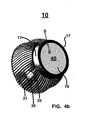
- FIGS. 4a and 4b the cooling device 10 is depicted with the heat spreader 40 already connected with the taper bore 14 and the fastener 45 inserted in the aperture 14a with the head 47 in contact with the boss 13 .
- the head 47 of the fastener can be substantially flat as illustrated or the head 47 can have a profile that complements the shape of the boss 13 in order to streamline the air flow F through the chamber 30.
- the mounting surface 19 of the heat spreader 40 is illustrated as being substantially flush with the base 17 of the heat mass 11 .
- the mounting surface 19 need not be flush with the base 17 .
- the mounting surface 19 can be inset from the base 17 or the mounting surface 19 can extend outward of the base 17 .
- the heat spreader is not mounted to the taper bore 14 of the heat mass 11 .
- the taper bore 14 includes an upper portion denoted as 14t where the aperture 14a terminates.
- the portion 14t is substantially planar (i.e. flat); however, the portion 14t can be arcuate or sloped and an actual shape of the portion 14t will depend on the shape of the heat spreader 40 because the shape of the taper bore 14 and the taper walls 41 of the heat spreader 40 should be complementary in order to facilitate mating the heat spreader 40 to the taper bore 14 and to increase a contact area between the heat spreader 40 and the heat mass 11 .
- a larger contact area increases heat transfer from the heat spreader 40 to the heat mass 11 and distributes the transferred heat over a larger surface area.
- the heat spreader 40 includes a taper wall 41 having a profile 41p that is a sloped profile such that the heat spreader has a shape of a cone.
- the shape of the heat spreader 40 is that of a frustum of a cone because a top surface 41t is flat.
- the top surface 41t complements the portion 14t of the taper bore 14 and the taper wall 41 complements the taper bore 14 (see FIG. 4c ).
- the shape of the heat spreader 40 and the taper bore 14 are not limited to the shapes illustrated herein.
- the heat spreader 40 includes a taper wall 41 with an arcuate profile and a top surface 41t that is flat.
- the heat spreader 40 includes a taper wall 41 with an arcuate profile. In either case, the taper bore 14 would include a complementary arcuate profile.
- a fan 70 is positioned to be mounted on the substantially planar portion 29a of the top face 29.
- the fan 70 generates an air flow (see reference letter F in FIG. 3a) into the chamber 30 of the cooling device 10 in a direction indicated by dashed arrow af.
- a shroud 73 houses a rotor hub 79 having a plurality of fan blades 77.
- the rotor hub 79 is rotatably mounted on a stator 71 and the fan blades 77 rotate in a direction indicated by arrow rr .
- Several holes 75 through the shroud 77 are adapted to receive a fastener 89.
- a mounting ring 80 including a frame 81 and several mounting fixtures 83 is abutted against a surface 37a of the smooth radially outward portion 37.
- the diameter of the smooth radially outward portion 37 at the surface 37a is greater than an inside diameter of the frame 81 of the mounting ring 80 so that the frame 81 can be urged into snug contact with the smooth radially outward portion 37 without sliding off of the vanes and fins ( 21, 23 ).
- the only way to slide the mounting ring 80 off of the vanes and fins ( 21, 23 ) is in the direction of the base 17 because the diameter of the vanes and fins ( 21, 23 ) narrows in that direction.
- the mounting fixtures 83 receive the fastener 89 and optionally an additional fastener 87 such that the fan 70 is firmly connected with the top face 29 as illustrated in FIG. 8.
- the fasteners ( 87, 89 ) can be a nut and bolt as shown or another type of fastener.
- a rotational axis B-B of the fan 70 is colinear with the axis Z-Z of the cooling device 10 when the fan 70 is connected with the mounting ring 80.
- suitable materials for the mounting ring 80 include but are not limited to metals, plastics, or ceramics.
- the mounting ring 80 can be produced by machining, casting, molding, and pressure diecasting.
- fasteners as one means of connecting the mounting ring 80 with the fan 70
- the present invention is not to be construed as being limited to fasteners only.
- a latch on the fan could mate with a complementary latching profile on the mounting ring 80 .
- the mounting ring 80 can be formed by an injection molding process, many possibilities exist for effectuating the mounting of the fan 70 to the mounting ring 80 and fasteners are an example of one of those many possibilities.
- the fan 70 is shown mounted on the substantially planar portion 29a of the top face 29 .
- a power lead 72 of the fan 70 is positioned so that it is not necessary for the power lead 72 to be routed through or to come into contact with the vanes or fins ( 21, 23 ).
- the power lead 72 can include additional wires such as one or more additional wires for communicating with a circuit that controls the fan 70 (e.g turning fan 70 on or off, or controlling fan speed) or for determining if the fan 70 is operating properly.
- FIG. 8 Although only one fan 70 is shown in FIG. 8, two or more fans 70 can be stacked one upon the other with the holes 75 aligned so that a longer fastener 89 can be inserted through the holes 75 an into the mounting fixtures 83 of the mounting ring 80 . Therefore, another advantage of the cooling device 10 of the present invention is that a plurality of fans can be used to generate the air flow F into the chamber 30.
- the use of more than one fan 70 allows for redundant cooling if one or more fans should fail.
- prior fan assisted heat sinks in which the fan is mounted in a cavity formed by the fins, it is very difficult to mount more than one fan in the cavity.
- the fan 70 is not mounted in the chamber 30 , the risks associated with routing the power lead 72 through the vanes 21 is eliminated because the fan 70 is mounted on the top face 29.
- a notch 31 can be formed in the fins 23.
- the notch 31 can have a shape the complements an indexing tab (not shown) on the shroud 73 so that when the fan 70 is mounted on the top face 29 the indexing tab mates with the notch 31.
- the notch 31 can be used to ensure proper orientation of the fan 70 with respect to the cooling device 10 and/or to prevent relative movement between the shroud 73 and the cooling device 10.
- the tangential orientation of the vanes 2, as was described above in reference to FIG. 6, can be determined by two factors.
- a first factor is a height h 1 from the top of the boss 13 to the top face 29.
- the vanes 21 can be tangential to the circle C t having a diameter of about 6.5 millimeters.
- a second factor is a height h 2 from the top of the boss 13 to a bottom 76 of the fan blades 77.
- the diameter of the circle C t can be from about 3.0 millimeters to about 12.0 millimeters when the height h 2 varies from about 2.0 millimeters to about 8.5 millimeters.
- the above are examples only and the heights ( h 1 , h 2 ) are not to be construed as being limited to the ranges set forth above.
- the angle ( ⁇ , ⁇ 1 , and ⁇ 2 ) at which the vanes 21 are inclined relative to the axis Z-Z as described above can be set to substantially match or closely approximate a pitch angle ⁇ of the fan blades 77 as illustrated in FIG. 9.
- the angles ( ⁇ , ⁇ 1 , and ⁇ 2 ) can be set so that they are within a predetermined range of the pitch angle ⁇ .
- the pitch angle ⁇ can be about 15.0 degrees and the angle ⁇ can be about 17.0 degrees or the pitch angle ⁇ can be about 12.0 degrees and the angle ⁇ 1 can be about 10.0 degrees and the angle ⁇ 2 can be about 8.0 degrees.
- cooling device 10 of the present invention Another advantage of the cooling device 10 of the present invention is that the aforementioned tangential orientation and inclination of the vanes 21 and the aerodynamically profiled first and second portions ( 25, 27 ) of the inner wall 26 provide a low resistance path to the air flow F thereby reducing airflow shock noise. Additionally, because of the low resistance path, the fan 70 can be a lower RPM fan which produces lower noise levels and can be operated on less power than a higher RPM fan.
- the cross-sectional view of the cooling device 10 in FIG. 9 also depicts radiuses for the arcuate shapes of the boss 13 , the groove 15, the second portion 27, the first arcuate surface profile 21a, and the second arcuate surface profile 23a.
- the arcuate profile of the boss 13 can have a radius r B that is dependent in part on a desired thermal mass for the boss 13. For instance, for a thermal mass of about 50.0 grams, the radius r B for the boss 13 is about 15.0 millimeters. Similarly, the arcuate profile of the groove 15 has a radius r G of about 2.5 millimeters.
- the actual values for r B and r G will be application dependent and the above values are examples only. The present invention is not to be construed as being limited to the values set forth above.
- the arcuate surface profiles for the first and second arcuate surface profiles ( 21a, 23a ) have a radius of r V and r F respectively.
- the radius r V can be from about 38.0 millimeters to about 45.0 millimeters and the radius r F can be from about 31.0 millimeters to about 38.0 millimeters.
- the second portion 27 of the inner wall 26 has a radius r C .
- the radius r C can be about 20.0 millimeters, for example.
- the actual values for r V , r F and r G will be application dependent and the above values are examples only. The present invention is not to be construed as being limited to the values set forth above.
- the above mentioned radiuses can be determined by a machining process used to form the cooling device 10. Reference points for the radiuses need not be relative to a point on the cooling device 10.
- the radiuses r B , r G and r C can be formed by a forging process. They can also be machined or produced using a diecasting process.
- the radiuses r v and r F can be formed by machining after forging the cooling device 10 from a blank or material.
- a fan 74 without a shroud is positioned over the top face 29 of the cooling device 10 by a space frame 90 .
- a stator 71 of the fan 74 is connected with the space frame 90 and a plurality of arms 91 span the width of the top face 29 and fingers 93 at the ends of the arms 91 clamp the space frame 90 to the cooling device 10 approximately at the surface 37a of the smooth radially outward portion 37. Consequently, a hub 79 and blades 77 of the fan 74 are positioned over the chamber 30 so that an air flow from the fan 74 can enter the chamber 30 as was described above.
- power leads 72 from the fan 74 can be routed away from the fins and vanes ( 21, 23 ) of the cooling device 10 and away from the fan blades 77.
- the space frame 90 can be integrally formed with the stator 71 or the space frame 90 can be made from a metal or plastic material, preferably plastic because it is electrically non-conductive.
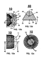
- the base 17 of the cooling device 10 includes at least two projections 22 that extend outward of the base 17 .
- a thermal interface material 24 is in contact with the mounting surface 19 of the heat spreader 40 and is positioned between the projections 22 .
- the projections 22 protect the thermal interface material 25 from damage when the mounting surface 19 is in contact with a component 50 .
- the projections 22 can also protect the thermal interface material from damage during manufacturing, transit, and/or handling.
- the thermal interface material 24 is in contact with a component face 51 of the component 50 and the thermal interface material 24 provides a thermally conductive path for waste heat from the component face 51 to be communicated through the mounting surface 19 and into the heat mass 11.
- the projections 22 prevent the thermal interface material 24 from being crushed, deformed, or otherwise damaged when the cooling device 10 is mounted on the component 50 and/or during manufacturing, transit, and handling.
- the projections 22 extend outward of the base 17 by a distance d p
- the distance d p will be application dependent and will depend on among other things a thickness of the thermal interface material 24.
- the distance d p can be from about 0.2 millimeters to about 1.0 millimeters.
- the mounting surface 19 is a substantially planar surface (i.e. it is substantially flat) and the mounting surface 19 is substantially perpendicular to the axis Z-Z (i.e. about 90.0 degrees, see angle ⁇ in FIG. 10 ).
- the thermal interface material 24 seals micro voids (i.e. gaps) between the mounting surface 19 and the component face 51 thereby enhancing thermal transfer from the component 50 to the cooling device 10.
- Suitable materials for the thermal interface material 24 include but are not limited to a thermally conductive paste, a thermally conductive grease, silicone, paraffin, a phase transition material, graphite, a coated aluminum foil, and carbon fiber.
- the thermal interface material 24 can be screen printed or pasted to the mounting surface 19 of the heat spreader 40 , for example.
- the mounting surface 19 of the heat spreader 40 can include the above mentioned projections 22 that extend outward of the mounting surface 19 by the distance d p and are operative to protect the thermal interface material 24 from damage as described above.
- the base 17 or the mounting surface 19 include the projections 22 .
- a system for dissipating heat 100 includes the cooling device 10 as described above, a fan 70 connected with the top face 29 as described above, a component 50 to be cooled by the cooling device 10 , and a base mount 300.
- a component face 51 of the component 50 is in contact with the mounting surface 19 , or as described above in reference to FIG. 11 , a thermal interface material 24 may be positioned intermediate between the component face 51 and the mounting surface 19.
- waste heat is thermally communicated through the component face 51 into the mounting surface 19 either by direct contact between the component face 51 and the mounting surface 19 or via the thermal interface material 24.
- the base mount 300 urges the mounting surface 19 and the component face 51 into contact with each other so that heat from the component is thermally communicated into the cooling device 10 .
- the mounting surface 19 of the heat spreader includes the projections 22 that extend outward of the mounting surface 19 and the thermal interface material 24 is positioned intermediate between the projections 22 as described above in reference to FIGS. 11 and 12d.
- the base 17 can include the projections 22 that extend outward of the base 17 and the thermal interface material 24 can be connected with the mounting surface 19 and positioned intermediate between the projections 22 as described above.
- the component 50 is carried by a support unit 99.
- the support unit includes but is not limited to a socket, a substrate, and a PC board.
- the socket can be mounted to a PC board in a manner that is well understood in the electronics art.
- the component can be a micro processor that is inserted into a socket that is solder onto a PC board.
- the base mount 300 is removably connected with the support unit 99 .
- the support unit can be a PC board on which the component 50 is soldered or otherwise electrically connected with.
- the cooling device 10 in terms of its usefulness in dissipating waste heat from electronic components, the cooling device 10 and the system 100 are not to be construed as being limited to cooling electronic devices exclusively.
- the component 50 can be any heat generating device from which it is desirable to remove heat.
- the support unit 99 need not be a PC board or a socket.
- the support unit 99 can be a substrate that carries the component 50.
- the component 50 may or may not be in electrical communication with the substrate.
- the base mount 300 is a base plate such as the type used for mounting a heat sink to a PC board.
- a plurality of holes 300a formed in the base mount 300 and a plurality of holes 99a formed in the support unit 99 receive fasteners ( 87, 89 ) that removably connect the base mount 300 with the support unit 99.
- fasteners 87, 89
- a nut and bolt are shown, other fasteners and other fastening methods can be used to removably connect the base mount 300 with the support unit 99.
- the system 100 can include a shroudless fan 74 as was described above in reference to FIG. 10 .
- the shroudless fan 74 includes the space frame 90 for supporting the fan 74 and for positioning the shroudless fan 74 adjacent to the top face 29 and over the chamber 30 so that the air flow af enters the chamber 30.
- the space frame 90 includes a plurality of arms 91 that span the width of the top face 29 and fingers 93 on the arms 91 clamp the space frame 90 to the smooth radially outward portion 37 of the outer wall 32 .
- the heat mass 11, the base 17 , and the vanes 21 are homogeneously formed.
- An extrusion process can be used to homogeneously form the heat mass 11, the base 17, and the vanes 21.
- the cooling device 10 can be made from a variety of thermally conductive materials including but not limited to copper, electrolytic copper, aluminum, and alloys of aluminum and copper, ceramics, and silicon ( Si ) substrates.
- An exemplary material for the cooling device 10 is aluminum 1060 or aluminum 6063.
- the heat mass 11, the base 17, and the vanes 21 can be homogeneously formed from an extruded rod or from a forged nutshell.
- the cooling device 10 can be manufactured by a variety of processes including but not limited to those listed below.
- First, the cooling device 10 can completely machining from an extruded bar stock.
- Second, a diecasting, forging, or pressing process can be used to form either one or both of the internal and external features ( 26, 32 ) of the cooling device 10 , followed by a machining process to form the base 17 , the mounting surface 19, the projections 22, the cylindrical neck 18, and the attachment groove 18g.
- Next cutting wheels can be used to form the primary P and secondary S slots for the vanes 21 and the fins 23 respectively, followed by deburring and degreasing.
- An exemplary model of the cooling device 10 was created with a diameter of 65 mm at the top face 29 and a diameter of 50 mm at the bottom surface 11a of the heat mass 11 .
- the base 17 had a diameter of 40 mm and height of 6.5 mm from the bottom surface 11a .
- the cooling device 10 had a total height from the mounting surface 19 to the top face 29 of about 38 mm.
- the heat mass 11 had a total height of about 22 mm from the mounting surface 19 to a top of the boss 13 .
- the smooth curved portion 33 had a radius of about 33 mm and the draft portion 35 had a diameter of about 63 mm.
- a Delta® fan, model number EFB0612VHB, and having dimensions of 60 mm x 60 mm x 15 mm in length, breadth, and height was mounted to the cooling device 10 as illustrated in FIG. 14.
- the cooling device 10 was then mounted on a processor carried by a PGA 370 connector that was soldered onto a mother board.
- the processor had a top surface of approximately 9 mm x 11 mm and a thermal output of 36 watts.
Landscapes
- Engineering & Computer Science (AREA)
- Physics & Mathematics (AREA)
- Thermal Sciences (AREA)
- Mechanical Engineering (AREA)
- General Engineering & Computer Science (AREA)
- Cooling Or The Like Of Electrical Apparatus (AREA)
- Cooling Or The Like Of Semiconductors Or Solid State Devices (AREA)
- Structures Of Non-Positive Displacement Pumps (AREA)
Abstract
Description
a cooling device for dissipating heat from a component that is in thermal communication with a heat spreader of the cooling device. The thermal communication can be by direct contact between the heat spreader and the component or by an intermediate material (e.g a thermal interface material) positioned between the cooling device and the component as will be described below. The component can be any heat source, such as an electrical component, for example.
Claims (24)
- A cooling device (10) for dissipating heat from a component (50), including:a heat mass (11) made from a first material and including a base (17), a boss (13) including a convex arcuate surface profile and a groove (15) surrounding the boss (13) and having a concave arcuate surface profile, the groove (15) and the boss (13) are symmetrically positioned about an axis Z-Z of the heat mass (11), a taper bore (14) extending from the base (11) to the boss (13), and an aperture (14a) extending from the boss (13) to the taper bore (14);a fastener (45) including a head (47) and a threaded shaft (49), the fastener (45) is inserted through the aperture (14a) with the head (17) in contact with the boss (17);a heat spreader (40) made from a second material that is dissimilar to the first material, the heat spreader (40) including a taper wall (41) with a profile that complements the taper bore (14), a mounting surface (19) operable to thermally connect the heat spreader (40) with the component (50), and a threaded aperture (43) adapted to receive the threaded shaft (49); anda plurality of vanes (21) in contact with the heat mass (11) and spaced apart to define a primary slot P therebetween that extends to the heat mass (11), the vanes (21) have a surface area that increases in radially outward direction R from the axis Z-Z,the vanes (21) including a top face (29), an aerodynamically profiled inner wall (26) including a first portion (25) extending from the groove (15) and terminating at a second portion (27) that extends to the top face (29), the inner walls (26) of the vanes (21) defining a chamber (30) that surrounds the groove (15), an outer wall (32) having a surface profile that widens from the base (17) of the heat mass (11) to the top face (29) and includes therebetween a smooth curved portion (33), a draft portion (35), and a smooth radially outward portion (37), andthe vanes (21) including at least one secondary slot S extending through a portion of each vane (21) to define a plurality of fins (23) in each vane (21), andwherein an air flow F entering the chamber (30) exits through the primary slots P and a bottom portion of the secondary slots S in an exhaust flow E that dissipates heat from the vanes (21) and the fins (23), the exhaust flow E creates a low pressure region ΔP within the chamber (30) that induces an intake flow I into the chamber (30) through the secondary slots S and a top portion of the primary slots P thereby dissipating heat from the fins (23) and the vanes (21), and the low pressure region ΔP induces a surface flow B along the first (25) and second portions (27) of the inner wall (26) so that the surface flow B passes over the groove (15) and the boss (13) to dissipate heat from the heat mass (11).
- A cooling device as in claim 1, wherein the heat mass (11), the base (17), and the vanes (21) are homogeneously formed.
- A cooling device as in claim 1 or 2, wherein the first material for the heat mass (11) is a material selected from the group of: aluminium, an aluminium alloy, copper, a copper alloy, and a ceramic, and
wherein the second material for the heat spreader (40) is material selected from the group of:copper, a copper alloy, silver, a silver alloy, silicon, gold, a gold alloy, graphite, a carbon fiber material, and a carbon fiber reinforced material. - A cooling device as in claim 1, 2 or 3, including:a thermal interface material (24) in contact with the mounting surface (19).
- A cooling device as in any preceding claim, including at least one fan (70) positioned adjacent to the top face (29) and positioned over the chamber (30) so that an air flow generated by the fan (70) produces the air flow F into the chamber (30).
- A cooling device in claim 5, including a mounting ring (80) arranged to abut against the smooth radially outward portion (37) and including a plurality of mounting fixtures (83) arranged to receive a fastener (89) that connects the fan (70) with the mounting ring (80) such that the fan (70) with the mounting ring (80) such that the fan (70) is fixedly connected with the top face (29).
- A cooling device as in claim 6, wherein at least a portion of the top face (29) is a substantially planar portion (29a) and the fan (70) is seated on the substantially planar portion (29a) when the fan (70) is connected with the top face (29).
- A cooling device as in any preceding claim, wherein the vanes (21) are tangentially oriented to a predetermined diameter of a circle Ct centered about the axis Z-Z.
- A cooling device as in claim 8, where in the predetermined diameter is from about 3.0 millimeters to about 12.0 millimeters.
- A cooling device as in any preceding claim, wherein the vanes (21) are inclined at an angle β with respect to the axis Z-Z.
- A cooling device as in claim 10, wherein the angle β at which the vanes are inclined is from about 5.0 degrees to about 25.0 degrees.
- A cooling device as in claim 10, wherein the angle at which the vanes are inclined comprises a first angle δ 1 from about 10.0 degrees to about 25.0 degrees, the first angle δ 1 measured along the smooth radially outward portion, and a second angle δ 2 from about 5.0 degrees to about 18.0 degrees measured along the smooth curved portion.
- A cooling device as in any preceding claim, wherein the arcuate surface profile of the boss (13) is a profile selected from the group of: a sphere. a frustum of a sphere, a cone, and a frustum of a cone.
- A cooling device as in any preceding claim, wherein the arcuate surface profile of the groove (15) is a semi-circular profile.
- A cooling device as in any preceding claim, wherein the primary slot P includes a first arcuate profile along the heat mass (11) and the first arcuate profile is a portion of an arc having a radius from about 38.0 millimeters to about 45.0 millimeters.
- A cooling device as in any preceding claim, wherein the secondary slot S extends to the heat mass (11) and the secondary slot S further includes a second arcuate profile (23a) along the heat mass (11) and the second arcuate profile (23a) is a portion of an arc having a radius from about 31.0 millimeters to about 38.0 millimeters.
- A cooling device as in any preceding claim, wherein the first portion (25) of the inner wall (26) is a sloped surface and the second portion (27) of the inner wall (26) is a concave arcuate surface.
- A cooling device as in any preceding claim, including:a shroudless fan (74) including a space frame (90) for supporting the fan (74) and for positioning the fan (74) adjacent to the top face (29) and over the chamber (30) so that an air flow af generated by the fan (74) produces the air flow F into the chamber (30).the space frame (90) including a plurality of arms (91) that span the top face (29), the arms (91) include fingers (93) at an end thereof, and the fingers (93) are adapted to clamp the space frame (90) to the smooth radially outward portion (37) of the outer wall (32).
- A cooling device as in any preceding claim, wherein the taper wall (41) of the heat spreader (40) has a profile selected from the group of: an arcuate profile and a slope profile.
- A cooling device as in any preceding claim, wherein the heat spreader (40) has a shape comprising a frustum of a cone.
- A cooling device as in any preceding claim, including:a plurality of projections (22) connected with and extending outward of a selected one of the mounting surface (19) of the heat spreader (40) or the base (17) of the heat mass (11); anda thermal interface material (24) in contact with the mounting surface (19) and positioned between the projections (22).
- A cooling device as in any preceding claim, wherein the fastener (45) is fixedly connected with a selected one of the heat mass (11), the heat spreader (40), or the heat mass (11) and the heat spreader (40).
- A cooling device as in any preceding claim, wherein the heat spreader (40) and the heat mass (11) are fixedly connected to each other.
- A cooling device as in any preceding claim, including:A thermal sealant (44) in contact with the taper bore (41) and the taper wall and operative to seal micro gaps between the taper bore (41 ) and the taper wall (14).
Applications Claiming Priority (2)
| Application Number | Priority Date | Filing Date | Title |
|---|---|---|---|
| US427670 | 2003-04-30 | ||
| US10/427,670 US6779593B1 (en) | 2003-04-30 | 2003-04-30 | High performance cooling device with heat spreader |
Publications (2)
| Publication Number | Publication Date |
|---|---|
| EP1473982A2 true EP1473982A2 (en) | 2004-11-03 |
| EP1473982A3 EP1473982A3 (en) | 2005-05-11 |
Family
ID=32869270
Family Applications (1)
| Application Number | Title | Priority Date | Filing Date |
|---|---|---|---|
| EP04251406A Withdrawn EP1473982A3 (en) | 2003-04-30 | 2004-03-11 | Cooling device |
Country Status (5)
| Country | Link |
|---|---|
| US (1) | US6779593B1 (en) |
| EP (1) | EP1473982A3 (en) |
| JP (1) | JP3987054B2 (en) |
| CN (1) | CN1542956A (en) |
| TW (1) | TWI325297B (en) |
Cited By (1)
| Publication number | Priority date | Publication date | Assignee | Title |
|---|---|---|---|---|
| EP3675152A1 (en) * | 2018-12-27 | 2020-07-01 | Avermedia Technologies, Inc. | Heat dissipation device |
Families Citing this family (38)
| Publication number | Priority date | Publication date | Assignee | Title |
|---|---|---|---|---|
| TW540985U (en) * | 2002-07-16 | 2003-07-01 | Delta Electronics Inc | Improved heat sink |
| TWM244508U (en) * | 2003-04-16 | 2004-09-21 | Asia Vital Components Co Ltd | Improved fan structure |
| US7063130B2 (en) * | 2003-08-08 | 2006-06-20 | Chu-Tsai Huang | Circular heat sink assembly |
| US20050161196A1 (en) * | 2004-01-22 | 2005-07-28 | Hsieh Hsin-Mao | Heat radiator for a CPU |
| US20050183843A1 (en) * | 2004-02-13 | 2005-08-25 | Fujikura Ltd. | Heat sink |
| US20060039116A1 (en) * | 2004-08-03 | 2006-02-23 | Egbon Electronics Ltd. | Heat-sinking base plate and its manufacturing method |
| US20060054311A1 (en) * | 2004-09-15 | 2006-03-16 | Andrew Douglas Delano | Heat sink device with independent parts |
| US7296619B2 (en) * | 2004-10-21 | 2007-11-20 | Hewlett-Packard Development Company, L.P. | Twin fin arrayed cooling device with heat spreader |
| US7028757B1 (en) | 2004-10-21 | 2006-04-18 | Hewlett-Packard Development Company, L.P. | Twin fin arrayed cooling device with liquid chamber |
| US7164582B2 (en) * | 2004-10-29 | 2007-01-16 | Hewlett-Packard Development Company, L.P. | Cooling system with submerged fan |
| US7891827B2 (en) * | 2006-03-09 | 2011-02-22 | Seiko Epson Corporation | Projector |
| JP2008091644A (en) | 2006-10-02 | 2008-04-17 | Nippon Densan Corp | Heat sink and heat sink cooling device |
| USD568829S1 (en) | 2006-10-12 | 2008-05-13 | Nidec Corporation | Heat sink |
| JP2008166465A (en) * | 2006-12-28 | 2008-07-17 | Nippon Densan Corp | Heat sink fan |
| USD564460S1 (en) | 2007-01-25 | 2008-03-18 | Nidec Corporation | Heat sink fan |
| USD576567S1 (en) | 2007-02-13 | 2008-09-09 | Nidec Corporation | Heat sink fan |
| USD600218S1 (en) | 2007-06-20 | 2009-09-15 | Nidec Corporation | Heat sink |
| US20090032218A1 (en) * | 2007-07-31 | 2009-02-05 | Adc Telecommunications, Inc. | Apparatus for transferring between two heat conducting surfaces |
| US8235094B2 (en) * | 2007-07-31 | 2012-08-07 | Adc Telecommunications, Inc. | Apparatus for transferring heat in a fin of a heat sink |
| US8051896B2 (en) * | 2007-07-31 | 2011-11-08 | Adc Telecommunications, Inc. | Apparatus for spreading heat over a finned surface |
| JP2009076507A (en) * | 2007-09-18 | 2009-04-09 | Nippon Densan Corp | Heat sink, heat sink fan and transport method thereof |
| USD593042S1 (en) | 2008-01-31 | 2009-05-26 | Nidec Corporation | Heat sink |
| JP5335339B2 (en) * | 2008-09-11 | 2013-11-06 | 株式会社エー・エム・テクノロジー | A heat radiator composed of a combination of a graphite-metal composite and an aluminum extruded material. |
| TWM353311U (en) * | 2008-10-07 | 2009-03-21 | Shi-Ming Chen | Improved heat dissipator |
| CN101826467B (en) * | 2009-03-02 | 2012-01-25 | 清华大学 | Preparation method of thermal interface material |
| CN201422226Y (en) * | 2009-05-06 | 2010-03-10 | 鸿富锦精密工业(深圳)有限公司 | Radiator combination |
| USD657089S1 (en) * | 2010-04-10 | 2012-04-03 | Lg Innotek Co., Ltd. | LED lamp |
| JP5338012B2 (en) * | 2010-09-30 | 2013-11-13 | ツォンシャン ウェイキアン テクノロジー カンパニー、リミテッド | High power heat dissipation module |
| JP2014103184A (en) * | 2012-11-19 | 2014-06-05 | Nippon Densan Corp | Heat sink and heat sink fan |
| JP5523542B1 (en) * | 2012-12-07 | 2014-06-18 | 三菱電機株式会社 | Cooling system |
| JP6077061B2 (en) * | 2015-07-08 | 2017-02-08 | 株式会社遠藤照明 | Heat sink and lighting device |
| US10794637B2 (en) * | 2016-10-03 | 2020-10-06 | Ge Aviation Systems Llc | Circular heatsink |
| JP6288900B1 (en) * | 2017-02-20 | 2018-03-07 | 三菱重工コンプレッサ株式会社 | Impeller, rotating machine, manufacturing method of impeller, and manufacturing method of rotating machine |
| EP3388682B1 (en) * | 2017-04-12 | 2021-11-17 | Pfeiffer Vacuum Gmbh | Vacuum pump with a heat sink and method for manufacturing the heat sink |
| US11466190B2 (en) | 2018-06-25 | 2022-10-11 | Abb Schweiz Ag | Forced air cooling system with phase change material |
| JP7570176B2 (en) * | 2019-12-26 | 2024-10-21 | ニデック株式会社 | Heat Sinks and Cooling Devices |
| CN112943703B (en) * | 2021-02-25 | 2022-06-17 | 山东英信计算机技术有限公司 | A fan module and server including the same |
| US12395023B2 (en) * | 2022-10-14 | 2025-08-19 | Beta Air Llc | Rotor for an electric aircraft motor and a method for manufacturing |
Family Cites Families (9)
| Publication number | Priority date | Publication date | Assignee | Title |
|---|---|---|---|---|
| JP2779537B2 (en) * | 1990-02-16 | 1998-07-23 | イビデン株式会社 | Finned electronic component mounting board |
| DE10031465B4 (en) * | 2000-06-28 | 2006-06-01 | eupec Europäische Gesellschaft für Leistungshalbleiter mbH & Co. KG | Cooling device for a circuit arrangement |
| US6404634B1 (en) * | 2000-12-06 | 2002-06-11 | Hewlett-Packard Company | Single piece heat sink for computer chip |
| USD464938S1 (en) | 2001-07-27 | 2002-10-29 | Hewlett Packard Company | High performance cooling device |
| US6505680B1 (en) * | 2001-07-27 | 2003-01-14 | Hewlett-Packard Company | High performance cooling device |
| US6508300B1 (en) | 2001-07-27 | 2003-01-21 | Hewlett Packard Company | Spring clip for a cooling device |
| US6543522B1 (en) | 2001-10-31 | 2003-04-08 | Hewlett-Packard Development Company, L.P. | Arrayed fin cooler |
| TW540985U (en) * | 2002-07-16 | 2003-07-01 | Delta Electronics Inc | Improved heat sink |
| US6631756B1 (en) * | 2002-09-10 | 2003-10-14 | Hewlett-Packard Development Company, L.P. | High performance passive cooling device with ducting |
-
2003
- 2003-04-30 US US10/427,670 patent/US6779593B1/en not_active Expired - Fee Related
- 2003-10-27 TW TW092129802A patent/TWI325297B/en not_active IP Right Cessation
-
2004
- 2004-01-30 CN CNA2004100025452A patent/CN1542956A/en active Pending
- 2004-03-11 EP EP04251406A patent/EP1473982A3/en not_active Withdrawn
- 2004-04-21 JP JP2004125644A patent/JP3987054B2/en not_active Expired - Fee Related
Cited By (1)
| Publication number | Priority date | Publication date | Assignee | Title |
|---|---|---|---|---|
| EP3675152A1 (en) * | 2018-12-27 | 2020-07-01 | Avermedia Technologies, Inc. | Heat dissipation device |
Also Published As
| Publication number | Publication date |
|---|---|
| US6779593B1 (en) | 2004-08-24 |
| CN1542956A (en) | 2004-11-03 |
| JP3987054B2 (en) | 2007-10-03 |
| EP1473982A3 (en) | 2005-05-11 |
| TW200423861A (en) | 2004-11-01 |
| TWI325297B (en) | 2010-05-21 |
| JP2004336031A (en) | 2004-11-25 |
Similar Documents
| Publication | Publication Date | Title |
|---|---|---|
| US6779593B1 (en) | High performance cooling device with heat spreader | |
| US6505680B1 (en) | High performance cooling device | |
| US6789610B1 (en) | High performance cooling device with vapor chamber | |
| US7028757B1 (en) | Twin fin arrayed cooling device with liquid chamber | |
| US6631756B1 (en) | High performance passive cooling device with ducting | |
| US7164582B2 (en) | Cooling system with submerged fan | |
| US7497248B2 (en) | Twin fin arrayed cooling device | |
| US6832410B2 (en) | High performance cooling device with side mount fan | |
| CN1303682C (en) | Radiation fin array cooler | |
| US6781834B2 (en) | Cooling device with air shower | |
| US7296619B2 (en) | Twin fin arrayed cooling device with heat spreader | |
| JP2008166465A (en) | Heat sink fan | |
| US6769175B2 (en) | Heat sink device manufacture | |
| JP2007281100A (en) | Heat sink fan unit | |
| HK1069679A (en) | High performance cooling device with heat spreader | |
| JP3982947B2 (en) | Heat sink fixing structure | |
| WO2006134316A1 (en) | A heat dissipating fan | |
| HK1064210A (en) | High performance passive cooling device with ducting |
Legal Events
| Date | Code | Title | Description |
|---|---|---|---|
| PUAI | Public reference made under article 153(3) epc to a published international application that has entered the european phase |
Free format text: ORIGINAL CODE: 0009012 |
|
| AK | Designated contracting states |
Kind code of ref document: A2 Designated state(s): AT BE BG CH CY CZ DE DK EE ES FI FR GB GR HU IE IT LI LU MC NL PL PT RO SE SI SK TR |
|
| AX | Request for extension of the european patent |
Extension state: AL HR LT LV MK |
|
| PUAL | Search report despatched |
Free format text: ORIGINAL CODE: 0009013 |
|
| AK | Designated contracting states |
Kind code of ref document: A3 Designated state(s): AT BE BG CH CY CZ DE DK EE ES FI FR GB GR HU IE IT LI LU MC NL PL PT RO SE SI SK TR |
|
| AX | Request for extension of the european patent |
Extension state: AL HR LT LV MK |
|
| AKX | Designation fees paid | ||
| REG | Reference to a national code |
Ref country code: DE Ref legal event code: 8566 |
|
| STAA | Information on the status of an ep patent application or granted ep patent |
Free format text: STATUS: THE APPLICATION IS DEEMED TO BE WITHDRAWN |
|
| 18D | Application deemed to be withdrawn |
Effective date: 20051112 |