EP1473878A2 - Wireless communication apparatus and wireless communication control method - Google Patents
Wireless communication apparatus and wireless communication control method Download PDFInfo
- Publication number
- EP1473878A2 EP1473878A2 EP04007654A EP04007654A EP1473878A2 EP 1473878 A2 EP1473878 A2 EP 1473878A2 EP 04007654 A EP04007654 A EP 04007654A EP 04007654 A EP04007654 A EP 04007654A EP 1473878 A2 EP1473878 A2 EP 1473878A2
- Authority
- EP
- European Patent Office
- Prior art keywords
- link level
- wlan
- value
- access point
- control parameter
- Prior art date
- Legal status (The legal status is an assumption and is not a legal conclusion. Google has not performed a legal analysis and makes no representation as to the accuracy of the status listed.)
- Withdrawn
Links
Images



Classifications
-
- H—ELECTRICITY
- H04—ELECTRIC COMMUNICATION TECHNIQUE
- H04W—WIRELESS COMMUNICATION NETWORKS
- H04W28/00—Network traffic management; Network resource management
- H04W28/16—Central resource management; Negotiation of resources or communication parameters, e.g. negotiating bandwidth or QoS [Quality of Service]
- H04W28/18—Negotiating wireless communication parameters
-
- H—ELECTRICITY
- H04—ELECTRIC COMMUNICATION TECHNIQUE
- H04W—WIRELESS COMMUNICATION NETWORKS
- H04W84/00—Network topologies
- H04W84/02—Hierarchically pre-organised networks, e.g. paging networks, cellular networks, WLAN [Wireless Local Area Network] or WLL [Wireless Local Loop]
- H04W84/10—Small scale networks; Flat hierarchical networks
- H04W84/12—WLAN [Wireless Local Area Networks]
-
- H—ELECTRICITY
- H04—ELECTRIC COMMUNICATION TECHNIQUE
- H04W—WIRELESS COMMUNICATION NETWORKS
- H04W88/00—Devices specially adapted for wireless communication networks, e.g. terminals, base stations or access point devices
- H04W88/08—Access point devices
Definitions
- Embodiments of the invention relate to a wireless communication device and a wireless communication control method.
- wireless LAN communications based on the Institute of Electronics and Electrical Engineers (IEEE) 802.11x standards feature a mechanism for dynamically changing a communication rate according to a communication status.
- IEEE 802.11x standards e.g., IEEE 802.11, 802.11a, 802.11b & 802.11g
- a communication rate having four stages of 1 Mbps, 2 Mbps, 5.5 Mbps, and 11 Mbps is defined and is controlled so as to transmit a communication packet at an appropriate communication rate according to a communication status between wireless stations for making wireless communication.
- Japanese Patent Application Publication (KOKAI) No. 2001-217896 discloses a wireless communication system that can adjust the communication rate from one to another in accordance with bit error rate parameter during actual data communication. More specifically, this system deploys a mechanism that statistically manages a communication status of an actual communication packet in order to set an appropriate communication rate. However, this may cause an unwanted transition between two different communication rates.
- a system may be adapted with a more gradual transition of the communication rate.
- a similar condition is used in both cases of raising and lowering the communication rate. For example, the communication rate is raised/lowered when the packet communication is successfully performed/fails ten times in succession.
- the present invention has been made in view of the above circumstances, and it is an object to provide a wireless communication apparatus capable of separately controlling a transition between a plurality of communication link levels for each wireless communication party or each communication packet type, and a wireless communication control method therefor.
- a wireless communication apparatus which has a database to store a link level and a control parameter associated with the first WLAN station, and a driver in communication with the database, the driver adjusting the link level if a value of the control parameter exceeds a predetermined maximum value and the link level is currently set at a level below a maximum link level.
- a “wireless communication apparatus” comprises a wireless communication device that is capable of adjusting communication rates to a plurality of communication link levels.
- the wireless communication device may be adapted as a computer (e.g., portable, desktop, server, etc.), personal digital assistant, cellular phone, a wireless LAN access point, or the like.
- the wireless communication apparatus further comprises a storing device for storing level management data corresponding to at least one of another (outside) communication device and a packet type used for wireless communication, and a controlling device for controlling a communication link level to be used by the wireless communication device on the basis of the level management data.
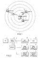
- FIG. 1 shows a correlation between a wireless LAN link level and a distance separating a wireless LAN access point (WLAN-AP) and a wireless LAN station (WLAN-STA).
- the WLAN-AP 1 is an electronic apparatus for distributing, for example, video data and the like through wireless communications in response to requests from the WLAN-STAs 2-4.
- Both the WLAN-AP 1 and the WLAN-STAs 2-4 are wireless communication devices that perform wireless communication based on the IEEE 802.11b standard.
- the WLAN-AP 1 and the WLAN-STA 2 are positioned in close proximity to each other and are connected at the link level of 11 Mbps.
- the WLAN-AP 1 and the WLAN-STA 3, which are in a slightly more distant positional relationship, are connected at the link level of 5.5 Mbps.
- the WLAN-AP 1 and the WLAN-STA WLAN-STA3, which are in a further distant positional relationship, are connected at the link level of 1 Mbps.
- the used link level is raised/lowered in proportion to the length of the distance between the both not considered.
- the raising/lowering of this link level was controlled by the respective WLAN-STA.
- Such control was performed in a uniform manner based solely on the distal proximity between the WLAN-AP 1 and the selected WLAN-STA 2, 3 or 4.
- the link level thereof is changed from 1 Mbps to 5.5 Mbps, and when it moves to the position of the WLAN-STA 2, the link level thereof is changed to 11 Mbps.
- this link level adjustment was performed without considering such loss fact. Further, even if a plurality of types of communication packets exchanged between the both are present depending on whether or not the loss is allowable to some degree, this fact is not considered.
- the changeover condition of this link level is appropriately used for each wireless communication device or each communication packet type.
- FIG. 2 shows an exemplary hardware configuration of the WLAN-AP 1.
- the WLAN-AP 1 comprises a CPU 11, a bridge device 12 coupled to the CPU 11, and a memory 13 coupled to the bridge device 12.
- the WLAN-AP 1 also includes an IDE controller 14, an hard disk drive (HDD) 15 coupled to the IDE controller 14, a wired LAN-MAC controller 16, a wired LAN-PHY controller 17 coupled to the wired LAN-MAC controller 16, a wireless LAN-MAC controller 18, and a wireless LAN-PHY controller 19 coupled to the wireless LAN-MAC controller 18.
- HDD hard disk drive
- the bridge device 12 is coupled to each IDE controller 14, the wired LAN-MAC controller 16, and the wireless LAN-MAC controller 18. Further, this WLAN-AP 1 is provided with a bus (e.g., Peripheral Component Interconnect "PCI" bus) A for connecting to other devices (e.g., PCI devices such as the IDE controller 14, the wired LAN-MAC controller 16, the wireless LAN-MAC controller 18, and the bridge device 12).
- PCI Peripheral Component Interconnect
- the CPU 11 controls the WLAN-AP 1 according to software loaded on the memory 13.
- the bridge device 12 controls data transfer between the CPU 11 and the memory 13, or the communications between the CPU 11 and the IDE controller 14, the wired LAN-MAC controller 16, and the wireless LAN-MAC controller 18.
- the CPU 11 may be deployed as a microprocessor, a digital signal processor, application specific integrated circuit, microcontroller or the like.
- the memory 13 stores a program to be executed by the CPU 11 therein, or is utilized as a temporary storage position of data required for the control of the system.
- the IDE controller 14 drives and controls the HDD 15.
- the HDD 15 stores a program for operating the WLAN-AP 1 or video data therein.
- the wired LAN-MAC controller 16 performs communication control of the wired LAN in association with the wired LAN-PHY controller 17.
- the wireless LAN-MAC controller 18 performs communication control of the wireless LAN in association with the wireless LAN-PHY controller 19.
- FIG. 3 shows an exemplary software configuration of the WLAN-AP 1.
- the WLAN-AP1 stores software within the memory 13 for execution or access by the CPU 11.
- the software comprises a video database (DB) 101, a video transmission application 102, a Web setting unit 103, an IP layer 104, a bridge 105, a wired LAN driver 106, a wireless LAN access point driver 107, and a wireless station control DB 108.
- DB video database
- the WLAN-AP1 stores software within the memory 13 for execution or access by the CPU 11.
- the software comprises a video database (DB) 101, a video transmission application 102, a Web setting unit 103, an IP layer 104, a bridge 105, a wired LAN driver 106, a wireless LAN access point driver 107, and a wireless station control DB 108.
- DB video database
- the video DB 101 stores video data sent by the video data transmission application 102 through the IP communication therein.
- the video data transmission application 102 utilizes Realtime Transfer Protocol (hereinafter "RTP") or the like to send the video data stored in the video DB 101 to a wireless communication device through the IP layer 104, bridge 105 and wireless LAN access point 107. Further, the video data transmission application 102 communicates with the wireless LAN access point driver 107 in order to adjust the packet link level control system in the RTP communication.
- RTP Realtime Transfer Protocol
- the Web setting unit 103 provides a setting function of, for example, in the form of homepage of causing a user to perform the setting of the present system.
- the IP layer 104 provides an IP communication function for the video data transmission application 102 or the Web setting unit 103.
- the bridge 105 controls transfer of MAC level packet between the IP layer 104 and the wired LAN driver 106, the wireless LAN access point driver 107.
- the wired LAN driver 106 is connected to the bridge 105 to control the communication packet of the wired LAN.
- the wireless LAN access point driver 107 provides a wireless LAN access point function, and performs control of the link level of the wireless LAN by utilizing information in the wireless station control DB 108. Further, the wireless LAN access point driver 107 provides a notice to the video data transmission application 102 of a control status of the wireless LAN as needed.
- the wireless station control DB 108 stores information for controlling the link level for each WLAN-STA connected to the wireless LAN access point function in the present system therein.
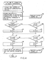
- FIG. 4 shows the operation of the link level control performed by the WLAN-AP 1.
- the wireless LAN access point driver'107 acquires a destination MAC address included in the packet (block A1). Also, the wireless LAN access point driver 107 acquires a link level Sn associated with a WLAN-STA "n" corresponding to this acquired destination MAC address, and a control parameter Pn from the wireless station control DB 108 (block A2).
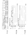
- FIG. 5 shows an example of control parameters (Pns) corresponding individual WLAN-STA A, B, and C.
- Pn of WLAN-STA A is 0, which means that the simplicity of both to raise a link level and to lower a link level are substantially equal to each other.
- Pn of WLAN-STA B is -20, which means that it is easier and quicker to lower the link level than it is to raise the link level.
- Pn of WLAN-STA C is 20, which means that it is easier and quicker to raise the link level than it is to lower a link level.
- the wireless LAN access point driver 107 checks a transmission status of the packet in the terminated packet transmission processing, and determines whether or not the packet transmission has been successfully performed (block A3). When the packet transmission has failed (NO in block A3), the wireless LAN access point driver 107 decrements a value of the control parameter Pn of the WLAN-STA "n" by one (block A4). For example, if it is the WLAN-STA B and the control parameter is -20 just before block A4, the parameter is decremented to -21.
- the wireless LAN access point driver 107 determines whether or not a retry processing has occurred in the transmission control of the MAC level of the wireless LAN at the time of actual transmission (block A5).
- the wireless LAN access point driver 107 increments the value of the control parameter Pn of the WLAN-STA "n" by one (block A6). For example, if it is the WLAN-STA B and the control parameter is -20 just before the block A5, the parameter is incremented to -19.
- the value of the control parameter Pn of the WLAN-STA "n" is incremented by one; when the packet transmission has been successfully performed in spite of the occurrence of the retry, the value of the control parameter Pn is maintained as it is'; and when the packet transmission has failed, the value of the control parameter Pn is decremented by one.
- the wireless LAN access point driver 107 increments the level of the link level Sn corresponding to the WLAN-STA "n” by one, and initializes the control parameter Pn to 0 (block A8).
- it instead of initializing the control parameter Pn to 0, it may be set to initial parameter value corresponding each WLAN-STA "n” shown in FIG. 5, e.g. to -20 if it is the WLAN-STA B.
- the wireless LAN access point driver 107 now determines whether or not the value of the control parameter Pn of the WLAN-STA "n” is smaller than Pmin which is -40 in this embodiment, and whether or not the value of the current link level of the WLAN-STA "n” is larger than a minimum value Smin of the link level which is 1 (block A9).
- the wireless LAN access point driver 107 decrements the level of the link level Sn corresponding to the WLAN-STA "n” by one, and initializes the control parameter Pn to 0 (block A10).
- it instead of initializing the control parameter Pn to 0, it may be set to initial parameter value corresponding each WLAN-STA "n” shown in FIG. 5, e.g. to -20 if it is the WLAN-STA B.
- the wireless LAN access point driver 107 updates the values Pn and Sn in the wireless station control DB 108 in order to maintain the values Pn and Sn after this update (block A11).
- FIGS. 6A and 6B are exemplary diagram showing transitions of the link level, where (A) shows a transition of the link level when a stable link level is an intermediate link level, and on the contrary (B) shows a transition of the link level when the stable link level is a maximum link level.
- FIG. 7 is a diagram exemplifying a recording GUI (Graphical User Interface) for specific control provided by the Web setting unit 103.
- GUI Graphic User Interface
- FIG. 8 shows an exemplary operation of the link level control performed by a wireless LAN access point (e.g., WLAN-AP 1 of FIG. 1) in the case that the conditions for identifying a packet is set by using the GUI shown in FIG. 7.
- a wireless LAN access point e.g., WLAN-AP 1 of FIG. 1
- the wireless LAN access point driver 107 acquires a destination MAC address of the packet (block B1). Further, the wireless LAN access point driver 107 acquires a link level Sn associated with a WLAN-STA "n" corresponding to this acquired destination MAC address, and a control parameter Pn from the wireless station control DB 108 (block B2).
- the wireless LAN access point driver 107 determines whether or not the MAC address is registered in the wireless station control DB 108 as a MAC address of the WLAN-STA targeted for the specific control (block B3).
- threshold values P1max and P1min for general processing are stored in the threshold values Pmax and Pmin of the control parameters (block B4).
- the threshold values P2max and P2min for the specific control are stored in the threshold values Pmax and Pmin of the control parameters (block B5).
- FIG. 9 shows one example of P1max, P1min, P2max, and P2min.
- the wireless LAN access point driver 107 checks a transmission status of the packet in the terminated packet transmission processing, and determines whether or not the packet transmission has been successfully performed (block B6). When the packet transmission has failed (NO in block B6), the wireless LAN access point driver 107 decrements the value of the control parameter Pn of the WLAN-STA "n" by one (block B7).
- the wireless LAN access point driver 107 determines whether or not a retry processing has occurred in the transmission control of the MAC level of the wireless LAN at the time of actual transmission (block B8). When the retry has not occurred (NO in block B8), the wireless LAN access point driver 107 increments the value of the control parameter Pn of the WLAN-STA "n" by one (block B9).
- the wireless LAN access point driver 107 determines whether or not the value of the control parameter Pn of the WLAN-STA “n” exceeds Pmax, and whether or not the value of the current link speed Sn of the WLAN-STA “n” is smaller than a maximum value Smax of the link level, which is set to 4 in this embodiment (block B10). When these conditions are satisfied (YES in block B10), the wireless LAN access point driver 107 increments the level of the link level Sn corresponding to the WLAN-STA "n” by one and initializes the control parameter Pn to 0 (block B11).
- the wireless LAN access point driver 107 now determines whether or not the value of the control parameter Pn of the WLAN-STA "n” is smaller than Pmin, and whether or not the value of the current link level of the WLAN-STA "n” is larger than a minimum value Smin of the link level (block B12).
- the wireless LAN access point driver 107 decrements the level of the link level Sn corresponding to the WLAN-STA "n” by one, and initializes the control parameter Pn to 0 (block B13).
- the wireless LAN access point driver 107 updates the values Pn and Sn in the wireless station control DB 108 in order to maintain the values Pn and Sn after this update (block B14).
- the wireless LAN access point manages the link level and controls of the transition thereof for each party or device, and additionally a plurality of link level changeover conditions are held and are appropriately utilized for each party or device.
- the setting of the link level changeover conditions may be performed by the GUI provided by the Web setting unit 103, and may be performed by the Web setting unit 103 in response to instructions from the WLAN-STAs 2-4.
- the wireless LAN access point driver 107 may automatically perform the setting according to the transmission status of the communication packet at any given time.
- the present invention is not restricted to the above-mentioned embodiment, and may modify and implement structure requirements in the implementation stage in a range, which does not depart from the spirit thereof.
- the initial value a control parameter Pn, Pmax, and Pmin may be changed to another value if it is appropriate under the concept of this invention. Also, the Sn showing current link speed, and the Smax/Smin showing maximum/minimum link speed value of WLAN-STA may be changed depending to the wireless communication standard used therewith.
- the management of the link level or the control of the transition thereof is performed or the changeover conditions are appropriately utilized for each wireless communication device/party, which may be performed for each communication packet type instead.
- the above function relating to the link level may be utilized as a function complementary to QoS.
- PCF Point Coordination Function
- DCF Distributed Coordination Function
- CFP Contention Free Period
- CP Contention Period
- the control functions of the CFP and the CP can be utilized as the functions complementary to the QoS.
- All of aforementioned embodiments are applicable to an apparatus and/or device in the field of wireless communication, i.e., a personal computer, a personal digital assistance, an audio/visual device, and so on.
Landscapes
- Engineering & Computer Science (AREA)
- Quality & Reliability (AREA)
- Computer Networks & Wireless Communication (AREA)
- Signal Processing (AREA)
- Mobile Radio Communication Systems (AREA)
- Small-Scale Networks (AREA)
Abstract
Description
Claims (18)
- A wireless local area network (WLAN) access point adapted for communication with a plurality of WLAN stations including a first WLAN station, characterized by comprising:a database (108) to store a link level and a control parameter associated with the first WLAN station; anda driver (107) in communication with the database, the driver adjusting the link level if a value of the control parameter exceeds a predetermined maximum value and the link level is currently set at a level below a maximum link level.
- The WLAN access point according to claim 1, characterized in that the link level is a code that represents a supported transmission rate with the first WLAN station.
- The WLAN access point according to claim 2, characterized in that the control parameter is an adjusted value to specify a time period for adjusting the link level.
- The WLAN access point according to claim 3, characterized in that the driver further adjusts the link level if the value of the control parameter is less than a predetermined minimum value and the link level is currently set at a level above a minimum link level.
- The WLAN access point according to claim 4, characterized in that the minimum link level is a value to specify a transmission rate of one million bits per second and the maximum link level is a value to specify a transmission rate of at least eleven million bits per second.
- The WLAN access point according to claim 4, characterized in that the driver controls the link level by acquiring a destination media access control (MAC) address from an incoming packet sent by the first WLAN station and obtaining the link level associated with the first WLAN station from the database.
- The WLAN access point according to claim 6, characterized in that the driver determines whether the destination MAC address is registered in the database and selects (i) a first predetermined maximum value and a first predetermined minimum value if the destination MAC address is registered or (ii) a second predetermined maximum value and a second predetermined minimum value if the destination MAC address is not registered.
- The WLAN access point according to claim 7, characterized in that the first predetermined maximum value is greater than the second predetermined maximum value.
- The WLAN access point according to claim 7, characterized in that the first predetermined maximum value is at least two times greater than the second predetermined maximum value.
- The WLAN access point according to claim 4, characterized in that the driver adjusts the link level when the value of the control parameter is less than the predetermined minimum value by decrementing the link level by one.
- The WLAN access point according to claim 1, characterized in that the driver resets the control parameter to a predetermined value and stores the adjusted link level and the reset control parameter within the database.
- The WLAN access point according to claim 1, characterized in that the driver adjusts the link level by incrementing the link level by one.
- A method for adjusting a link level to alter a transmission rate between a wireless local area network (WLAN) access point and a WLAN station, characterized by comprising the steps of:storing a link level and a control parameter associated with the WLAN station; andadjusting (A7, A9) the link level if a value of the control parameter exceeds a predetermined maximum value and the link level is currently set at a level below a maximum link level.
- The method according to claim 13, characterized in that the control parameter is a dynamically adjusted value to specify when the link level is to be adjusted.
- The method according to claim 13, characterized by further comprising the steps of:adjusting (A9, A10) the link level if the value of the control parameter is less than a predetermined minimum value and the link level is currently set at a level above a minimum link level.
- The method according to claim 15, characterized by further comprising the steps of:resetting (All) the control parameter to a predetermined value; andstoring the adjusted link level and the reset control parameter as updated values for the link level and the control parameter.
- The method according to claim 13, characterized in that the adjusting of the link level'comprises (i) acquiring a destination media access control (MAC) address from an incoming packet sent by the WLAN station and (ii) obtaining the link level associated with the WLAN station from a database.
- The method according to claim 17, the prior to adjusting the link level, the method characterized by further comprising:determining (B3, B4, B5) whether the destination MAC address is registered in the database and to select (i) a first predetermined maximum value and a first predetermined minimum value if the destination MAC address is registered or (ii) a second predetermined maximum value and a second predetermined minimum value if the destination MAC address is not registered, the first predetermined maximum value being greater than the second predetermined maximum value.
Applications Claiming Priority (2)
| Application Number | Priority Date | Filing Date | Title |
|---|---|---|---|
| JP2003124117A JP2004328652A (en) | 2003-04-28 | 2003-04-28 | Wireless communication device and wireless communication control method |
| JP2003124117 | 2003-04-28 |
Publications (2)
| Publication Number | Publication Date |
|---|---|
| EP1473878A2 true EP1473878A2 (en) | 2004-11-03 |
| EP1473878A3 EP1473878A3 (en) | 2009-01-14 |
Family
ID=32985566
Family Applications (1)
| Application Number | Title | Priority Date | Filing Date |
|---|---|---|---|
| EP20040007654 Withdrawn EP1473878A3 (en) | 2003-04-28 | 2004-03-30 | Wireless communication apparatus and wireless communication control method |
Country Status (3)
| Country | Link |
|---|---|
| US (1) | US20040213192A1 (en) |
| EP (1) | EP1473878A3 (en) |
| JP (1) | JP2004328652A (en) |
Families Citing this family (8)
| Publication number | Priority date | Publication date | Assignee | Title |
|---|---|---|---|---|
| JP3930387B2 (en) * | 2002-06-24 | 2007-06-13 | 株式会社エヌ・ティ・ティ・ドコモ | Transmission rate switching control method, mobile communication system, and mobile communication control apparatus in mobile communication system |
| TWI276244B (en) * | 2004-06-04 | 2007-03-11 | Wistron Neweb Corp | Wireless communication device capable of switching antennas according to data transmission information on network |
| JP4516880B2 (en) * | 2005-03-29 | 2010-08-04 | 株式会社エヌ・ティ・ティ・ドコモ | Transmission rate control method, mobile station and radio base station |
| JP4643354B2 (en) | 2005-05-02 | 2011-03-02 | 株式会社エヌ・ティ・ティ・ドコモ | Transmission rate control method, mobile station and radio base station |
| JP4506658B2 (en) * | 2005-11-30 | 2010-07-21 | ソニー株式会社 | Wireless communication system, communication apparatus, setting information providing method, setting information obtaining method, and computer program |
| US20080051094A1 (en) * | 2006-08-24 | 2008-02-28 | Nokia Corporation | System and method for facilitating communications |
| JP2009033274A (en) * | 2007-07-25 | 2009-02-12 | Nec Access Technica Ltd | Wireless LAN slave unit, wireless LAN network, and MAC address relearning method used therefor |
| WO2016166982A1 (en) * | 2015-04-16 | 2016-10-20 | 日本電気株式会社 | Communication device, communication method, and recording medium |
Family Cites Families (12)
| Publication number | Priority date | Publication date | Assignee | Title |
|---|---|---|---|---|
| US6016313A (en) * | 1996-11-07 | 2000-01-18 | Wavtrace, Inc. | System and method for broadband millimeter wave data communication |
| US5912921A (en) * | 1997-08-20 | 1999-06-15 | Intermec Ip Corp. | Concurrent multiple data rate communications in a wireless local area network |
| US6570849B1 (en) * | 1999-10-15 | 2003-05-27 | Tropic Networks Inc. | TDM-quality voice over packet |
| US6493331B1 (en) * | 2000-03-30 | 2002-12-10 | Qualcomm Incorporated | Method and apparatus for controlling transmissions of a communications systems |
| US6542736B1 (en) * | 2000-04-04 | 2003-04-01 | Telefonaktiebolaget Lm Ericsson (Publ) | Efficient radio link adaptation and base station sector selection in a radio communication system |
| US6882634B2 (en) * | 2000-04-07 | 2005-04-19 | Broadcom Corporation | Method for selecting frame encoding parameters to improve transmission performance in a frame-based communications network |
| JP2002026926A (en) * | 2000-07-07 | 2002-01-25 | Sony Corp | Wireless transmission method and wireless transmission device |
| US7257094B2 (en) * | 2001-01-16 | 2007-08-14 | Texas Instruments Incorporated | Jointly controlling transmission rate and power in a communications system |
| JP2002288073A (en) * | 2001-03-27 | 2002-10-04 | Toshiba Corp | Wireless network device and method |
| US20020181637A1 (en) * | 2001-05-31 | 2002-12-05 | Sumie Nakabayashi | Radio communication method and apparatus capable of changing transmission rate at every other party |
| JP2003051781A (en) * | 2001-05-31 | 2003-02-21 | Hitachi Kokusai Electric Inc | Data communication method and data communication method |
| JP3844425B2 (en) * | 2001-10-02 | 2006-11-15 | 日本電信電話株式会社 | Multi-rate radio base station equipment |
-
2003
- 2003-04-28 JP JP2003124117A patent/JP2004328652A/en active Pending
-
2004
- 2004-03-04 US US10/793,314 patent/US20040213192A1/en not_active Abandoned
- 2004-03-30 EP EP20040007654 patent/EP1473878A3/en not_active Withdrawn
Also Published As
| Publication number | Publication date |
|---|---|
| EP1473878A3 (en) | 2009-01-14 |
| US20040213192A1 (en) | 2004-10-28 |
| JP2004328652A (en) | 2004-11-18 |
Similar Documents
| Publication | Publication Date | Title |
|---|---|---|
| CN1894985B (en) | Control Decisions in Communication Systems | |
| EP1315341B1 (en) | Receiver polling for data transmission with sliding window data flow control | |
| CA2470458C (en) | Audio communication bandwidth management system, method and program for the same, communication connection server, and network apparatus | |
| JP3761486B2 (en) | Wireless LAN system, main device and program | |
| EP1925132B1 (en) | Managing negotiations of quality of service parameters in wireless networks | |
| JP2003516090A (en) | Method and system for applying bit rate to utilize service area | |
| US20080112343A1 (en) | Treatment of secondary management data as user data in an ieee 802.16 system scheduler | |
| US8589586B2 (en) | Method and apparatus for managing transmission of TCP data segments | |
| US20070133552A1 (en) | Packet-relay unit | |
| EP1563645A2 (en) | System and method for an ieee 802.11 access point to prevent traffic suffering bad link quality from affecting other traffic | |
| US8976658B1 (en) | Packet sampling using rate-limiting mechanisms | |
| US8954109B2 (en) | Access category enforcement in wireless local area networks | |
| US20040213192A1 (en) | Wireless communication apparatus and wireless communication control method | |
| US6463034B1 (en) | Method and apparatus for avoiding data loss during a PPP renegotiation on a Um interface | |
| JP3947739B2 (en) | Allocating memory resources for mobile stations | |
| EP1505759B1 (en) | Method and device for transmitting/receiving data using acknowledged transport layer protocols | |
| KR101018731B1 (en) | Method and apparatus for setting peak receive state variable in wireless communication system | |
| JP4930137B2 (en) | Wireless communication apparatus, wireless communication method and program | |
| US7933270B2 (en) | Method and system for prioritizing IP traffic in a wireless network based on a type-of-service identifier | |
| CN101370017A (en) | Method and apparatus for setting header in wireless communication system | |
| JP2007096776A (en) | Communication device | |
| KR100831456B1 (en) | Data flow control in wlan radio connections for the impairment of internet telephony | |
| KR100675138B1 (en) | Remote Upgrade Device and Method of VIO IP Wireless LAN Phone Using Wireless LAN | |
| CN114765593A (en) | Data transmission method, communication equipment and system | |
| CN101325778A (en) | Measurement Method of Streaming Media Service Quality of Service in Wideband Code Division Multiple Access System |
Legal Events
| Date | Code | Title | Description |
|---|---|---|---|
| PUAI | Public reference made under article 153(3) epc to a published international application that has entered the european phase |
Free format text: ORIGINAL CODE: 0009012 |
|
| 17P | Request for examination filed |
Effective date: 20040330 |
|
| AK | Designated contracting states |
Kind code of ref document: A2 Designated state(s): AT BE BG CH CY CZ DE DK EE ES FI FR GB GR HU IE IT LI LU MC NL PL PT RO SE SI SK TR |
|
| AX | Request for extension of the european patent |
Extension state: AL LT LV MK |
|
| PUAL | Search report despatched |
Free format text: ORIGINAL CODE: 0009013 |
|
| AK | Designated contracting states |
Kind code of ref document: A3 Designated state(s): AT BE BG CH CY CZ DE DK EE ES FI FR GB GR HU IE IT LI LU MC NL PL PT RO SE SI SK TR |
|
| AX | Request for extension of the european patent |
Extension state: AL LT LV MK |
|
| STAA | Information on the status of an ep patent application or granted ep patent |
Free format text: STATUS: THE APPLICATION HAS BEEN WITHDRAWN |
|
| 18W | Application withdrawn |
Effective date: 20090129 |