EP1473832A1 - Radio communication terminal and radio signal receiving method - Google Patents
Radio communication terminal and radio signal receiving method Download PDFInfo
- Publication number
- EP1473832A1 EP1473832A1 EP04090166A EP04090166A EP1473832A1 EP 1473832 A1 EP1473832 A1 EP 1473832A1 EP 04090166 A EP04090166 A EP 04090166A EP 04090166 A EP04090166 A EP 04090166A EP 1473832 A1 EP1473832 A1 EP 1473832A1
- Authority
- EP
- European Patent Office
- Prior art keywords
- power
- gain
- receiver
- antenna
- communication terminal
- Prior art date
- Legal status (The legal status is an assumption and is not a legal conclusion. Google has not performed a legal analysis and makes no representation as to the accuracy of the status listed.)
- Granted
Links
- 238000004891 communication Methods 0.000 title claims abstract description 40
- 238000000034 method Methods 0.000 title claims description 19
- 238000006243 chemical reaction Methods 0.000 claims description 8
- 230000000717 retained effect Effects 0.000 claims 2
- 230000001413 cellular effect Effects 0.000 description 1
- 238000010586 diagram Methods 0.000 description 1
- 238000005516 engineering process Methods 0.000 description 1
- 230000006870 function Effects 0.000 description 1
- 238000012986 modification Methods 0.000 description 1
- 230000004048 modification Effects 0.000 description 1
Images

Classifications
-
- H—ELECTRICITY
- H03—ELECTRONIC CIRCUITRY
- H03G—CONTROL OF AMPLIFICATION
- H03G3/00—Gain control in amplifiers or frequency changers
- H03G3/20—Automatic control
- H03G3/30—Automatic control in amplifiers having semiconductor devices
- H03G3/3052—Automatic control in amplifiers having semiconductor devices in bandpass amplifiers (H.F. or I.F.) or in frequency-changers used in a (super)heterodyne receiver
- H03G3/3068—Circuits generating control signals for both R.F. and I.F. stages
-
- H—ELECTRICITY
- H04—ELECTRIC COMMUNICATION TECHNIQUE
- H04B—TRANSMISSION
- H04B7/00—Radio transmission systems, i.e. using radiation field
- H04B7/02—Diversity systems; Multi-antenna system, i.e. transmission or reception using multiple antennas
- H04B7/04—Diversity systems; Multi-antenna system, i.e. transmission or reception using multiple antennas using two or more spaced independent antennas
- H04B7/08—Diversity systems; Multi-antenna system, i.e. transmission or reception using multiple antennas using two or more spaced independent antennas at the receiving station
- H04B7/0802—Diversity systems; Multi-antenna system, i.e. transmission or reception using multiple antennas using two or more spaced independent antennas at the receiving station using antenna selection
- H04B7/0805—Diversity systems; Multi-antenna system, i.e. transmission or reception using multiple antennas using two or more spaced independent antennas at the receiving station using antenna selection with single receiver and antenna switching
- H04B7/0808—Diversity systems; Multi-antenna system, i.e. transmission or reception using multiple antennas using two or more spaced independent antennas at the receiving station using antenna selection with single receiver and antenna switching comparing all antennas before reception
- H04B7/0811—Diversity systems; Multi-antenna system, i.e. transmission or reception using multiple antennas using two or more spaced independent antennas at the receiving station using antenna selection with single receiver and antenna switching comparing all antennas before reception during preamble or gap period
Definitions
- the present invention relates to radio communication terminals and receiving methods, and particularly to a radio communication terminal with automatic gain control (AGC) and to an antenna switching method.
- AGC automatic gain control
- a radio communication terminal In a Wideband Code Division Multiple Access (W-CDMA) system of the related art, a radio communication terminal has a plurality of antennas for RX(Receiving) diverse communications.
- the radio signals received through the antennas are combined with one another so that an optimal gain can be obtained.
- the radio communication terminal is small. Accordingly, it is difficult to provide a complicated circuit for executing the above operation in the radio communication terminal. Radio communication environments of the terminal are not constant since the radio communication terminal always moves with its user. Therefore, the radio communication terminal needs more complicated receiving processes.
- a receiving method that provides simple antenna switching procedure. Switching of the antennas is made based on the received signal power.
- An AGC receiver in the radio communication terminal measures the received power intensity.
- the AGC receiver amplifies a received radio signal by feedback-controlling.
- Japanese Unexamined Patent Application Publication No. 2002-135346 discloses an AGC circuit that calculates the power of an input signal during a short period. This AGC circuit makes it possible to obtain a targeted reception level at high speed in the beginning of operation.
- the prior art AGC technology offers the possibility that an unstable received radio signal caused by antenna switching may be used as received data.
- a radio communication terminal which includes a plurality of antennas, an antenna switching unit for switching one antenna to another, a receiver for amplifying a received signal under automatic gain control, a power calculator for calculating received signal power, a memory for storing the calculated power values, and a power determining unit for selecting an antenna which receives the largest signal power.
- the received signal is received during a high speed operation when the receiver starts.
- the radio communication terminal further includes a gain calculator for calculating a gain based on an output from the receiver.
- the gain calculator may output the gain to the power calculator and the gain controller.
- a radio signal receiving method which includes the steps of: receiving a radio signal through one antenna among a plurality of antennas by a receiver operating under automatic gain control; calculating the power of the received radio signal based on a gain and output of the receiver; switching the one antenna to another among the plurality of antennas; storing the calculated power for each of the antennas in a memory; calculating a gain based on the output of the receiver and setting the calculated gain in the receiver; and selecting, from the plurality of antennas, one antenna from which the largest power is obtained.
- an unstable received radio signal caused by antenna switching is not used as received data.
- the radio communication terminal includes antennas A and B, an antenna switching unit 2, and a direct conversion receiver 100, which is an AGC radio receiver.
- the radio communication terminal also includes an average power calculator 3, an AGC gain calculator 4, an instantaneous power calculator 5, a memory 6, and a received power determining unit 7.
- the direct conversion receiver 100 has analog-to-digital (A/D) converters 22a and 22b at its output side.
- the antennas A and B receive radio signals. Under the control of one of the instantaneous power calculator 5 or the received power determining unit 7, the antenna switching unit 2 selects one of antennas A and B.
- the direct conversion receiver 100 receives the radio signal received through the selected antenna.
- the receiver 100 is an AGC receiver employing direct conversion method.
- the receiver 100 directly converts a carrier wave frequency into a baseband frequency. Accordingly, receiver 100 does not need an intermediate frequency (IF) filter.
- the receiver 100 has a built-in gain controller 107. When the radio communication terminal starts receiving signals, the receiver 100 sets gain controller 107 in a very short updating period.
- gain controller 107 includes a gain control amplifier (GCA). It takes a relatively long time for the GCA to stabilize.
- GCA gain control amplifier
- the direct conversion receiver 100 includes gain controller 107 (including the GCA), a high frequency amplifier 101, orthogonal mixers 102a and 102b, and a local oscillator 103.
- the receiver 100 also includes a 90-degree phase shifter 104, low-pass filters (LPFs) 105a and 105b, and band-pass amplifiers 106a and 106b.
- the gain controller 107 (including the GCA) controls the above three amplifiers 101, 106a, and 106b.
- the amplifiers 101, 106a, and 106b amplify the received signal at the set gain.
- the orthogonal mixers 102a and 102b each orthogonally transform the received signal to an I component signal and a Q component signal.
- the A/D converters 22a and 22b respectively convert the I signal and the Q signal output from the receiver 100 from analog to digital form.
- the average power calculator 3 calculates the average power of the I signal and Q signal converted in digital form.
- the average power is output to the AGC gain calculator 4 and the instantaneous power calculator 5.
- the AGC gain calculator 4 calculatesthe gain based on the average power, and outputs the calculated gain to gain controller 107 (including the GCA) and instantaneous power calculator 5.
- AGC gain calculator 4 functions to retain the gain until it is required.
- instantaneous power calculator 5 calculates an instantaneous received power of the received radio signal.
- the memory 6 stores the calculated received power. At this time, when memory 6 stores such received power of a radio signal received through the same antenna, the calculated power is added to the stored received power, and the obtained received power is stored.
- the memory 6 stores the received power of received radio signals for each antenna.
- the received power determining unit 7 compares the received power of the received radio signals stored in memory 6.
- the unit 7 controls antenna switching unit 2 to select an antenna from which a signal with larger received power is received.
- instantaneous power calculator 5 calculates the instantaneous received power a number of times, unit 7 compares the averages of the received powers.
- the above radio communication terminal can be, for example, a cellular phone.
- Fig. 2 shows an example of operation of the above radio communication terminal.
- gain controller 107 including the GCA
- updating of the period of the set gain is performed at high speed.
- a consecutive operation (described later) is performed four times for each antenna.
- the radio communication terminal selects either antenna A or B.
- the high speed operation is switched to an usual AGC operation. In the usual AGC operation, switching of antennas A and B is not performed.
- the radio communication terminal starts at time t1.
- the antenna switching unit 2 has selected the antenna A beforehand.
- the direct conversion receiver 100 receives the radio signal received through the antenna A.
- the gain controller 107 (including the GCA) has a predetermined gain beforehand.
- the direct conversion receiver 100 amplifies the radio signal received through the antenna A at the above gain.
- the A/D converters 22a and 22b convert amplified signals from analog form to digital form.
- the average power calculator 3 calculates the average received power of the digitized signals. Since the gain controller 107 (including the GCA) has the predetermined gain beforehand, gain controller 107 (including the GCA) is stable in a period (just after the radio communication terminal starts) from time t1 to time t4. Therefore, the average power calculator 3 can calculate an average received power in an arbitrary period (t1 to t2, or t3 to t4).
- average power calculator 3 outputs the average received power to AGC gain calculator 4 and instantaneous power calculator 5.
- instantaneous power calculator 5 selects antenna B by transmitting a control signal to the antenna switching unit 2. Switching to antenna B is completed at time t3.
- the instantaneous power calculator 5 obtains an instantaneous received power from antenna A by dividing the average received power of the radio signal received through antenna A by the gain set in AGC gain calculator 4.
- instantaneous power calculator 5 stores the calculated power in memory 6.
- the AGC gain calculator 4 calculates the gain (to be set in the gain controller 107 (including the GCA)) based on the difference between the present average received power of the radio signal received through the antenna A and the targeted value.
- average power calculator 3 completes calculating the next average received power
- AGC gain calculator 4 outputs the calculated gain to gain controller 107 (including the GCA) and instantaneous power calculator 5.
- the AGC gain calculator 4 retains the calculated gain until time t4.
- antenna B starts to receive a radio signal.
- gain controller 107 (including the GCA) has a predetermined gain. Accordingly, the radio signal received through antenna B is amplified with that gain.
- the average power calculator 3 calculates an average received power between time t3 and time t4, and outputs the calculated average received power to AGC gain calculator 4 and instantaneous power calculator 5 at time t4.
- the instantaneous power calculator 5 selects antenna A by transmitting a control signal to the antenna switching unit 2. Switching to antenna A is completed at time t5. At time t4, the instantaneous power calculator 5 obtains an instantaneous received power from antenna B by dividing the average received power of the signal received through antenna B by the gain transmitted from the AGC gain calculator 4.
- the instantaneous power calculator 5 stores the received power of the radio signal received through antenna B. At this time, when the memory 6 has already stored a received power of the radio signal received through antenna B, the calculated received power is added to the stored received power, and the obtained received power is stored. The instantaneous power calculator 5 stores the instantaneous received power for each of the antennas in the memory 6.
- the AGC gain calculator 4 calculates gain (to be set in the gain controller 107 (including the GCA)) based on the difference between the present average received power of the radio signal received through antenna B and the targeted value.
- the average power calculator 3 completes calculating the next average received power
- the AGC gain calculator 4 outputs the calculated gain to gain controller 107 (including the GCA) and instantaneous power calculator 5.
- AGC gain calculator 4 retains the calculated gain until time t7.
- the period (e.g., time t6 to time t7) in which the average power calculator 3 calculates the average power is within the period (e.g., time t6 to time t7) for updating the set gain in gain controller 107 (including the GCA) and after gain controller 107 (including the GCA) stabilizes.
- the above operation is executed four times for each antenna. After that, the operation shown in Fig. 3 starts.
- Fig. 3 shows an example of operation which is executed in a period in which the high speed operation shifts to normal AGC operation.
- memory 6 stores the (fourth) received power of the radio signal received through antenna A which is calculated by the instantaneous power calculator 5.
- memory 6 stores the (fourth) received power of the radio signal received through antenna B which is calculated by the instantaneous power calculator 5.
- the received power determining unit 7 compares the average (or total) instantaneous received powers obtained through antennas A and B which are stored in memory 6.
- the received power determining unit 7 selects one antenna from which a larger received power is obtained.
- radio signal reception through the selected antenna is initiated.
- This receiving operation is a normal AGC operation without switching between antennas A and B. Also, after that, high speed operation can be maintained. In this case, high speed operation can be shifted to normal AGC operation.
Landscapes
- Engineering & Computer Science (AREA)
- Computer Networks & Wireless Communication (AREA)
- Signal Processing (AREA)
- Radio Transmission System (AREA)
- Circuits Of Receivers In General (AREA)
- Mobile Radio Communication Systems (AREA)
Abstract
Description
- The present invention relates to radio communication terminals and receiving methods, and particularly to a radio communication terminal with automatic gain control (AGC) and to an antenna switching method.
- In a Wideband Code Division Multiple Access (W-CDMA) system of the related art, a radio communication terminal has a plurality of antennas for RX(Receiving) diverse communications. In the radio communication terminal, in order to improve receiving signal quality, the radio signals received through the antennas are combined with one another so that an optimal gain can be obtained. The radio communication terminal is small. Accordingly, it is difficult to provide a complicated circuit for executing the above operation in the radio communication terminal. Radio communication environments of the terminal are not constant since the radio communication terminal always moves with its user. Therefore, the radio communication terminal needs more complicated receiving processes.
- In addition, a receiving method that provides simple antenna switching procedure. Switching of the antennas is made based on the received signal power. An AGC receiver in the radio communication terminal measures the received power intensity. The AGC receiver amplifies a received radio signal by feedback-controlling. For example, Japanese Unexamined Patent Application Publication No. 2002-135346 discloses an AGC circuit that calculates the power of an input signal during a short period. This AGC circuit makes it possible to obtain a targeted reception level at high speed in the beginning of operation. However, the prior art AGC technology offers the possibility that an unstable received radio signal caused by antenna switching may be used as received data.
- According to an aspect of the present invention, a radio communication terminal is provided which includes a plurality of antennas, an antenna switching unit for switching one antenna to another, a receiver for amplifying a received signal under automatic gain control, a power calculator for calculating received signal power, a memory for storing the calculated power values, and a power determining unit for selecting an antenna which receives the largest signal power. And the received signal is received during a high speed operation when the receiver starts.
- Preferably, the radio communication terminal further includes a gain calculator for calculating a gain based on an output from the receiver. The gain calculator may output the gain to the power calculator and the gain controller.
- According to another aspect of the invention, a radio signal receiving method is provided which includes the steps of: receiving a radio signal through one antenna among a plurality of antennas by a receiver operating under automatic gain control; calculating the power of the received radio signal based on a gain and output of the receiver; switching the one antenna to another among the plurality of antennas; storing the calculated power for each of the antennas in a memory; calculating a gain based on the output of the receiver and setting the calculated gain in the receiver; and selecting, from the plurality of antennas, one antenna from which the largest power is obtained.
- According to the invention, an unstable received radio signal caused by antenna switching is not used as received data.
- The above and other objects, features, and advantages of the invention will become apparent from the following detailed description when taken with the accompanying drawings in which:
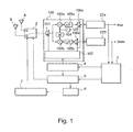
- Fig. 1 is a block diagram showing a radio communication terminal according to an embodiment of the invention;
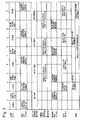
- Fig. 2 is a time chart showing an example of a receiving operation of the radio communication terminal shown in Fig. 1 when it is started; and
- Fig. 3 is a time chart showing an example of a process in which the radio communication terminal shown in Fig. 1 shifts to an AGC operation.
-
- Referring to Fig. 1, an example of a Direct Spread Code Division Multiple Access (DS-CDMA) radio communication terminal is shown as a radio communication terminal according to an embodiment of the invention. The radio communication terminal includes antennas A and B, an
antenna switching unit 2, and adirect conversion receiver 100, which is an AGC radio receiver. The radio communication terminal also includes anaverage power calculator 3, anAGC gain calculator 4, aninstantaneous power calculator 5, amemory 6, and a receivedpower determining unit 7. Thedirect conversion receiver 100 has analog-to-digital (A/D)converters 22a and 22b at its output side. - The antennas A and B receive radio signals. Under the control of one of the
instantaneous power calculator 5 or the receivedpower determining unit 7, theantenna switching unit 2 selects one of antennas A and B. Thedirect conversion receiver 100 receives the radio signal received through the selected antenna. Thereceiver 100 is an AGC receiver employing direct conversion method. Thereceiver 100 directly converts a carrier wave frequency into a baseband frequency. Accordingly,receiver 100 does not need an intermediate frequency (IF) filter. Thereceiver 100 has a built-in gain controller 107. When the radio communication terminal starts receiving signals, thereceiver 100sets gain controller 107 in a very short updating period. In this embodiment,gain controller 107 includes a gain control amplifier (GCA). It takes a relatively long time for the GCA to stabilize. - The
direct conversion receiver 100 includes gain controller 107 (including the GCA), ahigh frequency amplifier 101,orthogonal mixers local oscillator 103. Thereceiver 100 also includes a 90-degree phase shifter 104, low-pass filters (LPFs) 105a and 105b, and band-pass amplifiers amplifiers amplifiers orthogonal mixers D converters 22a and 22b respectively convert the I signal and the Q signal output from thereceiver 100 from analog to digital form. - The
average power calculator 3 calculates the average power of the I signal and Q signal converted in digital form. The average power is output to theAGC gain calculator 4 and theinstantaneous power calculator 5. TheAGC gain calculator 4 calculatesthe gain based on the average power, and outputs the calculated gain to gain controller 107 (including the GCA) andinstantaneous power calculator 5. AGC gaincalculator 4 functions to retain the gain until it is required. Based on the average power and the reciprocal of the gain output fromAGC gain calculator 4,instantaneous power calculator 5 calculates an instantaneous received power of the received radio signal. Thememory 6 stores the calculated received power. At this time, whenmemory 6 stores such received power of a radio signal received through the same antenna, the calculated power is added to the stored received power, and the obtained received power is stored. Thememory 6 stores the received power of received radio signals for each antenna. The receivedpower determining unit 7 compares the received power of the received radio signals stored inmemory 6. Theunit 7 controls antenna switchingunit 2 to select an antenna from which a signal with larger received power is received. Wheninstantaneous power calculator 5 calculates the instantaneous received power a number of times,unit 7 compares the averages of the received powers. The above radio communication terminal can be, for example, a cellular phone. - Fig. 2 shows an example of operation of the above radio communication terminal. In this example, when the radio communication terminal starts, in gain controller 107 (including the GCA), updating of the period of the set gain is performed at high speed. In this high speed operation, a consecutive operation (described later) is performed four times for each antenna. At the end of high speed operation, the radio communication terminal selects either antenna A or B. After that, the high speed operation is switched to an usual AGC operation. In the usual AGC operation, switching of antennas A and B is not performed.
- Referring to Fig. 2, the radio communication terminal starts at time t1. At this time, the
antenna switching unit 2 has selected the antenna A beforehand. Thedirect conversion receiver 100 receives the radio signal received through the antenna A. - At time t1, the gain controller 107 (including the GCA) has a predetermined gain beforehand. The
direct conversion receiver 100 amplifies the radio signal received through the antenna A at the above gain. The A/D converters 22a and 22b convert amplified signals from analog form to digital form. Theaverage power calculator 3 calculates the average received power of the digitized signals. Since the gain controller 107 (including the GCA) has the predetermined gain beforehand, gain controller 107 (including the GCA) is stable in a period (just after the radio communication terminal starts) from time t1 to time t4. Therefore, theaverage power calculator 3 can calculate an average received power in an arbitrary period (t1 to t2, or t3 to t4). - At time t2,
average power calculator 3 outputs the average received power toAGC gain calculator 4 andinstantaneous power calculator 5. When receiving the average received power of the radio signal received through antenna A,instantaneous power calculator 5 selects antenna B by transmitting a control signal to theantenna switching unit 2. Switching to antenna B is completed at time t3. At time t2, theinstantaneous power calculator 5 obtains an instantaneous received power from antenna A by dividing the average received power of the radio signal received through antenna A by the gain set inAGC gain calculator 4. - At time t3,
instantaneous power calculator 5 stores the calculated power inmemory 6. Whenmemory 6 has already stored received power from the antenna A, the calculated instantaneous received power is added to the stored received power, and the obtained power is stored. At time t3, theAGC gain calculator 4 calculates the gain (to be set in the gain controller 107 (including the GCA)) based on the difference between the present average received power of the radio signal received through the antenna A and the targeted value. At the time (time t4)average power calculator 3 completes calculating the next average received power,AGC gain calculator 4 outputs the calculated gain to gain controller 107 (including the GCA) andinstantaneous power calculator 5. TheAGC gain calculator 4 retains the calculated gain until time t4. - At time t3, antenna B starts to receive a radio signal. At time t3, gain controller 107 (including the GCA) has a predetermined gain. Accordingly, the radio signal received through antenna B is amplified with that gain. The
average power calculator 3 calculates an average received power between time t3 and time t4, and outputs the calculated average received power toAGC gain calculator 4 andinstantaneous power calculator 5 at time t4. - At time t4, when receiving the average received power of the signal received through antenna B, the
instantaneous power calculator 5 selects antenna A by transmitting a control signal to theantenna switching unit 2. Switching to antenna A is completed at time t5. At time t4, theinstantaneous power calculator 5 obtains an instantaneous received power from antenna B by dividing the average received power of the signal received through antenna B by the gain transmitted from theAGC gain calculator 4. - At time t5, the
instantaneous power calculator 5 stores the received power of the radio signal received through antenna B. At this time, when thememory 6 has already stored a received power of the radio signal received through antenna B, the calculated received power is added to the stored received power, and the obtained received power is stored. Theinstantaneous power calculator 5 stores the instantaneous received power for each of the antennas in thememory 6. - At time t5, the
AGC gain calculator 4 calculates gain (to be set in the gain controller 107 (including the GCA)) based on the difference between the present average received power of the radio signal received through antenna B and the targeted value. At the time (time t7) theaverage power calculator 3 completes calculating the next average received power, theAGC gain calculator 4 outputs the calculated gain to gain controller 107 (including the GCA) andinstantaneous power calculator 5.AGC gain calculator 4 retains the calculated gain until time t7. - The period (e.g., time t6 to time t7) in which the
average power calculator 3 calculates the average power is within the period (e.g., time t6 to time t7) for updating the set gain in gain controller 107 (including the GCA) and after gain controller 107 (including the GCA) stabilizes. In this embodiment, the above operation is executed four times for each antenna. After that, the operation shown in Fig. 3 starts. - Fig. 3 shows an example of operation which is executed in a period in which the high speed operation shifts to normal AGC operation. At time t23,
memory 6 stores the (fourth) received power of the radio signal received through antenna A which is calculated by theinstantaneous power calculator 5. At time t26,memory 6 stores the (fourth) received power of the radio signal received through antenna B which is calculated by theinstantaneous power calculator 5. At time t26, the receivedpower determining unit 7 compares the average (or total) instantaneous received powers obtained through antennas A and B which are stored inmemory 6. At time t27, by transmitting a control signal to theantenna switching unit 2, the receivedpower determining unit 7 selects one antenna from which a larger received power is obtained. At time t28, radio signal reception through the selected antenna is initiated. This receiving operation is a normal AGC operation without switching between antennas A and B. Also, after that, high speed operation can be maintained. In this case, high speed operation can be shifted to normal AGC operation. - During high speed operation, which is executed when the radio communication terminal starts, processing, such as encoding of a received radio signal, is not performed. Therefore, the received radio signal is not used as received data.
- In the invention, during high speed operation when the radio communication terminal starts, selection and setting of an antenna from which the largest received power is obtained are performed. Thus, in AGC operation after high speed operation, an unstable received radio signal caused by antenna switching is not used as received data.
- While the invention has been described in connection with certain preferred embodiments, it is to be understood that the subject matter encompassed by the invention is not limited to those specific embodiments. On the contrary, it is intended to include all alternatives, modifications, and equivalents as can be included within the sprit and scope of the following claims.
Claims (18)
- A radio communication terminal comprising:wherein the received signal is received during a high speed operation when the receiver starts.a plurality of antennas;an antenna switching unit for switching an antenna to another one;a receiver for amplifying a received signal under automatic gain control;a power calculator for calculating received signal power;a memory for storing the calculated power values; anda power determining unit for selecting an antenna which receives the largest signal power; and
- The radio communication terminal according to claim 1, further comprising a gain calculator for calculating the gain based on the output from the receiver.
- The radio communication terminal according to claim 2, further comprising a gain controller,
wherein the gain calculator outputs the gain to the power calculator and the gain controller. - The radio communication terminal according to claim 1,
wherein the power control unit controls the antenna switching unit to switch the antenna. - The radio communication terminal according to claim 1,
wherein the power determining unit compares the power values stored in the memory for each of the antennas. - The radio communication terminal according to claim 1,
wherein, based on a gain and output of the receiver, the power calculator calculates the power of a signal received through each of the antennas. - The radio communication terminal according to claim 1,
wherein the receiver employs direct conversion methods. - The radio communication terminal according to claim 2, further comprising an average power calculator for calculating the average power of a plurality of signals output from the receiver.
- The radio communication terminal according to claim 8,
wherein the average power calculator outputs the average power to the gain calculator and the power calculator. - A radio signal receiving method comprising the steps of:receiving a radio signal through one of a plurality of antennas by a receiver operating under automatic gain control;calculating the power of the received radio signal based on a gain and output of said receiver;switching the antenna to another one;storing the calculated power for each of the antennas in a memory;calculating the gain based on the output of said receiver and setting the calculated gain in said receiver; andselecting an antenna which receivesthe signal with the largest power.
- The radio signal receiving method according to claim 10, further comprising a step of calculatingthe average power of a plurality of signals output from the receiver.
- The radio signal receiving method according to claim 10, wherein each of the steps is executed during high speed operation of said receiver when said receiver starts.
- The radio signal receiving method according to claim 11, wherein calculation of the average power is performed within a period in which a predetermined gain is retained in the receiver and after the receiver stabilizes.
- The radio signal receiving method according to claim 11, wherein, when calculation of the average power is initially executed, the calculation is performed within a period in which a predetermined gain is retained in the receiver.
- The radio signal receiving method according to claim 10, wherein the power of the radio signal is calculated a number of times for each of the antennas.
- The radio signal receiving method according to claim 15, wherein the calculated powers are added up.
- The radio signal receiving method according to claim 11, wherein setting of the calculated gain in the receiver is performed after calculation of the next average power has ended.
- The radio signal receiving method according to claim 11, wherein switching of one antenna to another one is performed after calculation of the average power has ended.
Applications Claiming Priority (2)
| Application Number | Priority Date | Filing Date | Title |
|---|---|---|---|
| JP2003123408A JP4189656B2 (en) | 2003-04-28 | 2003-04-28 | Mobile phone antenna switching method using AGC receiver and mobile terminal thereof |
| JP2003123408 | 2003-04-28 |
Publications (2)
| Publication Number | Publication Date |
|---|---|
| EP1473832A1 true EP1473832A1 (en) | 2004-11-03 |
| EP1473832B1 EP1473832B1 (en) | 2013-12-18 |
Family
ID=32985551
Family Applications (1)
| Application Number | Title | Priority Date | Filing Date |
|---|---|---|---|
| EP04090166.2A Expired - Lifetime EP1473832B1 (en) | 2003-04-28 | 2004-04-27 | Radio communication terminal and radio signal receiving method |
Country Status (4)
| Country | Link |
|---|---|
| US (1) | US7366263B2 (en) |
| EP (1) | EP1473832B1 (en) |
| JP (1) | JP4189656B2 (en) |
| CN (1) | CN1543086A (en) |
Families Citing this family (15)
| Publication number | Priority date | Publication date | Assignee | Title |
|---|---|---|---|---|
| JP2007529160A (en) * | 2003-10-15 | 2007-10-18 | 松下電器産業株式会社 | Diversity receiving apparatus and radio receiving apparatus using the same |
| JP2006174126A (en) * | 2004-12-16 | 2006-06-29 | Matsushita Electric Ind Co Ltd | Diversity receiving apparatus and method |
| DE102005020062B4 (en) * | 2005-04-29 | 2011-07-21 | Globalfoundries Inc. | Mobile wireless data storage device and corresponding method for storing data |
| US7359690B2 (en) * | 2005-05-20 | 2008-04-15 | Agere Systems Inc. | Single path front end with digital AGC in SDARS system |
| US7978773B2 (en) * | 2006-12-29 | 2011-07-12 | Agere Systems Inc. | Multi-channel receiver with improved AGC |
| US7809343B2 (en) | 2007-04-25 | 2010-10-05 | Agere Systems Inc. | Multi-channel receiver with improved AGC |
| US7769357B2 (en) * | 2007-04-25 | 2010-08-03 | Agere Systems Inc. | Multi-channel receiver with improved AGC |
| CN101321380B (en) * | 2007-06-04 | 2011-10-05 | 华为技术有限公司 | Switch method, mobile station and switching arrangement |
| GB2458542A (en) * | 2008-03-28 | 2009-09-30 | Nokia Corp | Automatic gain control system |
| CN101604959B (en) * | 2009-07-09 | 2012-02-08 | 合肥邦立电子股份有限公司 | Automatic gain vehicle active antenna amplifier |
| JP5935044B2 (en) | 2011-01-27 | 2016-06-15 | パナソニックIpマネジメント株式会社 | Receiver |
| CN104662803B (en) * | 2012-09-25 | 2016-10-19 | 瑞典爱立信有限公司 | Receptor is arranged and method therein |
| US8923452B2 (en) * | 2013-03-18 | 2014-12-30 | Lockheed Martin Corporation | Noise-based gain adjustment and amplitude estimation system |
| CN106658567B (en) * | 2016-12-09 | 2020-05-22 | 厦门安胜网络科技有限公司 | Mobile communication terminal detection equipment |
| JP7504932B2 (en) * | 2022-02-09 | 2024-06-24 | アンリツ株式会社 | Wireless terminal test device and wireless terminal test method |
Citations (6)
| Publication number | Priority date | Publication date | Assignee | Title |
|---|---|---|---|---|
| WO1995009494A1 (en) * | 1993-09-30 | 1995-04-06 | Pacific Communication Sciences, Inc. | Multiple antenna home base for digital cordless telephones |
| EP0886388A2 (en) * | 1997-06-19 | 1998-12-23 | Mitsubishi Denki Kabushiki Kaisha | Transmitter, receiver and power control in a data transmission system |
| EP1065805A2 (en) * | 1999-06-30 | 2001-01-03 | Nec Corporation | Diversity CDMA reception apparatus having only one CDMA receiving part |
| WO2001052429A1 (en) * | 2000-01-10 | 2001-07-19 | Airnet Communications Corporation | A method and apparatus for automatic gain control on a time slot by time slot basis |
| US20020071507A1 (en) * | 2000-10-27 | 2002-06-13 | Nec Corporation | Reception AGC circuit |
| US20020118780A1 (en) * | 2001-02-28 | 2002-08-29 | Hurley James Patrick | Pro-active antenna switching based on relative power |
Family Cites Families (5)
| Publication number | Priority date | Publication date | Assignee | Title |
|---|---|---|---|---|
| GB2311693B (en) * | 1996-03-29 | 2000-06-21 | Nokia Mobile Phones Ltd | Antenna selection control circuitry |
| US6154503A (en) * | 1996-06-07 | 2000-11-28 | Sharp Kk Corporation | Automatic gain control system that responds to baseband signal distortion |
| US6226507B1 (en) * | 1998-02-03 | 2001-05-01 | Ericsson Inc. | Apparatus and method for selecting between a plurality of antennas utilized by a microcellular communications terminal for reception of a signal |
| US6292019B1 (en) * | 1999-05-07 | 2001-09-18 | Xilinx Inc. | Programmable logic device having configurable logic blocks with user-accessible input multiplexers |
| FI113819B (en) * | 2000-10-17 | 2004-06-15 | Nokia Corp | Method for receiving radio frequency signal and receiving apparatus |
-
2003
- 2003-04-28 JP JP2003123408A patent/JP4189656B2/en not_active Expired - Fee Related
-
2004
- 2004-04-22 US US10/829,172 patent/US7366263B2/en not_active Expired - Fee Related
- 2004-04-27 EP EP04090166.2A patent/EP1473832B1/en not_active Expired - Lifetime
- 2004-04-28 CN CNA2004100375988A patent/CN1543086A/en active Pending
Patent Citations (6)
| Publication number | Priority date | Publication date | Assignee | Title |
|---|---|---|---|---|
| WO1995009494A1 (en) * | 1993-09-30 | 1995-04-06 | Pacific Communication Sciences, Inc. | Multiple antenna home base for digital cordless telephones |
| EP0886388A2 (en) * | 1997-06-19 | 1998-12-23 | Mitsubishi Denki Kabushiki Kaisha | Transmitter, receiver and power control in a data transmission system |
| EP1065805A2 (en) * | 1999-06-30 | 2001-01-03 | Nec Corporation | Diversity CDMA reception apparatus having only one CDMA receiving part |
| WO2001052429A1 (en) * | 2000-01-10 | 2001-07-19 | Airnet Communications Corporation | A method and apparatus for automatic gain control on a time slot by time slot basis |
| US20020071507A1 (en) * | 2000-10-27 | 2002-06-13 | Nec Corporation | Reception AGC circuit |
| US20020118780A1 (en) * | 2001-02-28 | 2002-08-29 | Hurley James Patrick | Pro-active antenna switching based on relative power |
Also Published As
| Publication number | Publication date |
|---|---|
| CN1543086A (en) | 2004-11-03 |
| JP4189656B2 (en) | 2008-12-03 |
| US20040214529A1 (en) | 2004-10-28 |
| US7366263B2 (en) | 2008-04-29 |
| EP1473832B1 (en) | 2013-12-18 |
| JP2004328581A (en) | 2004-11-18 |
Similar Documents
| Publication | Publication Date | Title |
|---|---|---|
| EP1473832B1 (en) | Radio communication terminal and radio signal receiving method | |
| US6941112B2 (en) | Gain control amplification circuit and terminal equipment having the same | |
| US5640686A (en) | Radio communication device capable of communication in a plurality of communication systems | |
| US7065164B1 (en) | Automatic gain control and wireless communication device | |
| CN111162809B (en) | Wireless receiver and wireless device | |
| EP1083668A1 (en) | Radio terminal unit | |
| EP1061643B1 (en) | Receiver and gain control method of the same | |
| US7430406B2 (en) | Gain control in a wireless device | |
| US20050107115A1 (en) | Mobile multimode terminal with joint power amplifier | |
| US20030003886A1 (en) | Radio transmission apparatus and radio transmission method | |
| KR100735326B1 (en) | Low Power Wireless Transceiver with Subsampling Structure | |
| US8027644B2 (en) | Transceiver system including dual low-noise amplifiers | |
| EP1083673A1 (en) | Radio device and transmitting/receiving method | |
| JP2001339455A (en) | Receiving device and wireless communication device | |
| JP2001244861A (en) | Wireless receiving apparatus and method | |
| JP3479839B2 (en) | Receive AGC circuit | |
| JPH08288881A (en) | Automatic gain control system | |
| CN114257258B (en) | Wireless radio frequency receiver and data detection method | |
| US20240039569A1 (en) | Signal receiver and signal receiving method | |
| CN112235009B (en) | A communication method and system | |
| JP2002261656A (en) | Automatic gain control device for CDMA receiver | |
| JP2004147004A (en) | Booster device | |
| JP2001186069A (en) | Mobile radio terminal | |
| JP2006512828A (en) | Control technique for mobile handset transmit power | |
| KR19990085914A (en) | Wireless receiver with automatic gain control |
Legal Events
| Date | Code | Title | Description |
|---|---|---|---|
| PUAI | Public reference made under article 153(3) epc to a published international application that has entered the european phase |
Free format text: ORIGINAL CODE: 0009012 |
|
| AK | Designated contracting states |
Kind code of ref document: A1 Designated state(s): AT BE BG CH CY CZ DE DK EE ES FI FR GB GR HU IE IT LI LU MC NL PL PT RO SE SI SK TR |
|
| AX | Request for extension of the european patent |
Extension state: AL HR LT LV MK |
|
| 17P | Request for examination filed |
Effective date: 20041101 |
|
| 17Q | First examination report despatched |
Effective date: 20050107 |
|
| AKX | Designation fees paid |
Designated state(s): DE FR GB IT |
|
| GRAP | Despatch of communication of intention to grant a patent |
Free format text: ORIGINAL CODE: EPIDOSNIGR1 |
|
| INTG | Intention to grant announced |
Effective date: 20130708 |
|
| RIN1 | Information on inventor provided before grant (corrected) |
Inventor name: KENJI, TERAO |
|
| GRAS | Grant fee paid |
Free format text: ORIGINAL CODE: EPIDOSNIGR3 |
|
| GRAA | (expected) grant |
Free format text: ORIGINAL CODE: 0009210 |
|
| AK | Designated contracting states |
Kind code of ref document: B1 Designated state(s): DE FR GB IT |
|
| REG | Reference to a national code |
Ref country code: GB Ref legal event code: FG4D |
|
| REG | Reference to a national code |
Ref country code: DE Ref legal event code: R081 Ref document number: 602004044004 Country of ref document: DE Owner name: LENOVO INNOVATIONS LIMITED, HK Free format text: FORMER OWNER: NEC CORP., TOKYO, JP |
|
| REG | Reference to a national code |
Ref country code: DE Ref legal event code: R096 Ref document number: 602004044004 Country of ref document: DE Effective date: 20140213 |
|
| REG | Reference to a national code |
Ref country code: DE Ref legal event code: R097 Ref document number: 602004044004 Country of ref document: DE |
|
| PLBE | No opposition filed within time limit |
Free format text: ORIGINAL CODE: 0009261 |
|
| STAA | Information on the status of an ep patent application or granted ep patent |
Free format text: STATUS: NO OPPOSITION FILED WITHIN TIME LIMIT |
|
| REG | Reference to a national code |
Ref country code: GB Ref legal event code: 732E Free format text: REGISTERED BETWEEN 20141023 AND 20141029 |
|
| 26N | No opposition filed |
Effective date: 20140919 |
|
| REG | Reference to a national code |
Ref country code: FR Ref legal event code: TP Owner name: LENOVO INNOVATIONS LIMITED (HONG KONG), HK Effective date: 20141119 |
|
| REG | Reference to a national code |
Ref country code: DE Ref legal event code: R097 Ref document number: 602004044004 Country of ref document: DE Effective date: 20140919 |
|
| REG | Reference to a national code |
Ref country code: FR Ref legal event code: PLFP Year of fee payment: 13 |
|
| PGFP | Annual fee paid to national office [announced via postgrant information from national office to epo] |
Ref country code: IT Payment date: 20160418 Year of fee payment: 13 |
|
| REG | Reference to a national code |
Ref country code: FR Ref legal event code: PLFP Year of fee payment: 14 |
|
| PGFP | Annual fee paid to national office [announced via postgrant information from national office to epo] |
Ref country code: FR Payment date: 20170313 Year of fee payment: 14 |
|
| REG | Reference to a national code |
Ref country code: DE Ref legal event code: R082 Ref document number: 602004044004 Country of ref document: DE Representative=s name: STORK BAMBERGER PATENTANWAELTE PARTMBB, DE Ref country code: DE Ref legal event code: R081 Ref document number: 602004044004 Country of ref document: DE Owner name: LENOVO INNOVATIONS LIMITED, HK Free format text: FORMER OWNER: NEC CORP., TOKYO, JP Ref country code: DE Ref legal event code: R082 Ref document number: 602004044004 Country of ref document: DE Representative=s name: KASTEL PATENTANWAELTE PARTG MBB, DE |
|
| PG25 | Lapsed in a contracting state [announced via postgrant information from national office to epo] |
Ref country code: IT Free format text: LAPSE BECAUSE OF NON-PAYMENT OF DUE FEES Effective date: 20170427 |
|
| REG | Reference to a national code |
Ref country code: DE Ref legal event code: R082 Ref document number: 602004044004 Country of ref document: DE Representative=s name: KASTEL PATENTANWAELTE PARTG MBB, DE |
|
| PG25 | Lapsed in a contracting state [announced via postgrant information from national office to epo] |
Ref country code: FR Free format text: LAPSE BECAUSE OF NON-PAYMENT OF DUE FEES Effective date: 20180430 |
|
| PGFP | Annual fee paid to national office [announced via postgrant information from national office to epo] |
Ref country code: DE Payment date: 20190430 Year of fee payment: 16 |
|
| PGFP | Annual fee paid to national office [announced via postgrant information from national office to epo] |
Ref country code: GB Payment date: 20190429 Year of fee payment: 16 |
|
| REG | Reference to a national code |
Ref country code: DE Ref legal event code: R119 Ref document number: 602004044004 Country of ref document: DE |
|
| PG25 | Lapsed in a contracting state [announced via postgrant information from national office to epo] |
Ref country code: DE Free format text: LAPSE BECAUSE OF NON-PAYMENT OF DUE FEES Effective date: 20201103 |
|
| GBPC | Gb: european patent ceased through non-payment of renewal fee |
Effective date: 20200427 |
|
| PG25 | Lapsed in a contracting state [announced via postgrant information from national office to epo] |
Ref country code: GB Free format text: LAPSE BECAUSE OF NON-PAYMENT OF DUE FEES Effective date: 20200427 |