EP1473806A2 - Connecting device with a mounting thread - Google Patents
Connecting device with a mounting thread Download PDFInfo
- Publication number
- EP1473806A2 EP1473806A2 EP04102329A EP04102329A EP1473806A2 EP 1473806 A2 EP1473806 A2 EP 1473806A2 EP 04102329 A EP04102329 A EP 04102329A EP 04102329 A EP04102329 A EP 04102329A EP 1473806 A2 EP1473806 A2 EP 1473806A2
- Authority
- EP
- European Patent Office
- Prior art keywords
- thread
- mounting
- plug device
- mounting plate
- interruption
- Prior art date
- Legal status (The legal status is an assumption and is not a legal conclusion. Google has not performed a legal analysis and makes no representation as to the accuracy of the status listed.)
- Withdrawn
Links
- 238000007789 sealing Methods 0.000 claims abstract description 6
- 230000013011 mating Effects 0.000 claims description 9
- 230000000903 blocking effect Effects 0.000 claims 1
- 238000009434 installation Methods 0.000 description 4
- 230000000295 complement effect Effects 0.000 description 2
- 239000004020 conductor Substances 0.000 description 2
- 230000003993 interaction Effects 0.000 description 2
- 238000013459 approach Methods 0.000 description 1
- 230000008878 coupling Effects 0.000 description 1
- 238000010168 coupling process Methods 0.000 description 1
- 238000005859 coupling reaction Methods 0.000 description 1
- 230000006378 damage Effects 0.000 description 1
- 230000000994 depressogenic effect Effects 0.000 description 1
- 239000013013 elastic material Substances 0.000 description 1
- 238000004519 manufacturing process Methods 0.000 description 1
- 230000001681 protective effect Effects 0.000 description 1
- 238000009751 slip forming Methods 0.000 description 1
- 239000007787 solid Substances 0.000 description 1
Images


Classifications
-
- H—ELECTRICITY
- H01—ELECTRIC ELEMENTS
- H01R—ELECTRICALLY-CONDUCTIVE CONNECTIONS; STRUCTURAL ASSOCIATIONS OF A PLURALITY OF MUTUALLY-INSULATED ELECTRICAL CONNECTING ELEMENTS; COUPLING DEVICES; CURRENT COLLECTORS
- H01R13/00—Details of coupling devices of the kinds covered by groups H01R12/70 or H01R24/00 - H01R33/00
- H01R13/73—Means for mounting coupling parts to apparatus or structures, e.g. to a wall
- H01R13/74—Means for mounting coupling parts in openings of a panel
- H01R13/746—Means for mounting coupling parts in openings of a panel using a screw ring
-
- F—MECHANICAL ENGINEERING; LIGHTING; HEATING; WEAPONS; BLASTING
- F16—ENGINEERING ELEMENTS AND UNITS; GENERAL MEASURES FOR PRODUCING AND MAINTAINING EFFECTIVE FUNCTIONING OF MACHINES OR INSTALLATIONS; THERMAL INSULATION IN GENERAL
- F16B—DEVICES FOR FASTENING OR SECURING CONSTRUCTIONAL ELEMENTS OR MACHINE PARTS TOGETHER, e.g. NAILS, BOLTS, CIRCLIPS, CLAMPS, CLIPS OR WEDGES; JOINTS OR JOINTING
- F16B37/00—Nuts or like thread-engaging members
- F16B37/08—Quickly-detachable or mountable nuts, e.g. consisting of two or more parts; Nuts movable along the bolt after tilting the nut
- F16B37/0807—Nuts engaged from the end of the bolt, e.g. axially slidable nuts
- F16B37/085—Nuts engaged from the end of the bolt, e.g. axially slidable nuts with at least one unthreaded portion in both the nut and the bolt
Definitions
- the invention relates to a plug device element with an assembly thread for connection to another component. It also relates to a connector system containing at least one connector element a mounting thread and a mounting plate with at least one Recess for the connector element.
- Plug devices are used to easily manufacture and separate To provide connection between electrical conductors. They consist of Plugs with metallic contact pins and sockets (also called sockets) with metallic contact sockets into which the contact pins are inserted can.
- plugs and sockets are from the prior art (hereinafter generally referred to as "connector elements") with a Mounting thread known, on which a cover housing with a cable entry can be screwed on.
- the plug device element according to the invention has an assembly thread Connection with another component such as a cover housing or a mounting plate.
- the mounting thread can both be an internal thread and preferably also be an external thread.
- the mounting thread starts with an incomplete (i.e. less than 360 °) orbit Section that is interrupted by the subsequent section of the Assembly thread is separated.
- Such an assembly thread can be used with a corresponding or complementary trained counter thread in a quick assembly less than a full turn of 360 ° into a connection position be screwed together, despite the incomplete revolution Achieved even contact over the circumference with balanced force distribution can be.
- the latter is e.g. for a proper pressing of a elastic seal between the plug element and the other Component required. Due to the short turn of less than 360 ° this can be done Plug device element also installed in confined spaces in which no full rotation for screwing in is possible. hereby especially screwing in several closely adjacent connector elements allows in the recesses of a mounting plate without that further fixation means such as one to be screwed on from the back Union nut would be required.
- the use of the mounting thread on the connector element has the further advantage that this can also be used in the conventional way with a "normal" Thread can be screwed together. Therefore, the connector element without a design change, for example with one as needed conventional cover housing are connected, in which several Revolutions are possible or necessary, or with a mounting plate, in which, for reasons of space, less than one for screwing in Full rotation is available.
- the mounting thread further interruptions, which with the first, in Connection to the first thread section lying in the axial interruption Align direction.
- the mounting thread can be used with a Corresponding counter-threads first over one or more threads be plugged together before screwing the thread starts. This has the advantage that several threads turn to hold at the same time contribute and that, if necessary, intermediate components of different thicknesses between the plug element and the associated further Component can be accommodated.
- the plug device system according to the invention has the advantage that a Quick assembly of connector elements by simply screwing them in is possible in the recesses of the mounting plate.
- a connector system with the described properties can be used can be realized in different ways.
- the connector element is formed in the manner explained above, i.e. his
- the mounting thread begins with a section that does not run all the way round by an interruption from the following section of the assembly thread is separated.
- the corresponding mating thread also shows one first section an interruption, the dimensioning of the thread is coordinated so that the first section of the one thread in each case through the Interruption of the other thread can be performed.
- the desired bolting properties are also indicated by a Mounting thread and a counter thread, which is multi-start are trained.
- multi-start threads by definition, more than runs a thread line helically around the threaded shaft. Through the Multi-threading becomes a large axial pitch of each individual thread line reached, so that even a short rotation through 360 ° - ⁇ a large axial Can be covered, for example for pressing a seal sufficient.
- the individual begins offset from one another Thread lines achieved that in the connection position the respective Angular ranges of 360 ° - ⁇ over which the thread lines abut each other, are also offset from one another. Hence the angular range over which no In any case, there is contact between the screwed parts smaller than ⁇ .
- the recesses of the mounting plate are optionally surrounded by a collar, wherein the corresponding counter thread is formed in the collar.
- the Collar provides sufficient height to accommodate the mounting thread and can protrude on one or both sides of the mounting plate. If the collar is high, is also for a distance between the surface of the Mounting plate and the plug-in element to be screwed in, which prevents collisions with any protrusions on the mounting plate.
- this has Locking means through which the connection position against a Twisting is blocked.
- the locking means can thus Clear end position of the screw connection defined and against unintentional loosening can be secured.
- the Locking means are available to the person skilled in the art in various ways Available.
- the locking means as a radial and / or axially resiliently projecting projection be formed, which in a corresponding Recess clicks into the other part.
- the locking means can be designed in such a way that it can be easily can only be unlocked with a tool or only with destruction.
- a captive is along the recess of the mounting plate Sealing element arranged, which after reaching the installation position of the plug device element its connection to the mounting plate is watertight closes.
- the sealing element can e.g. an o-ring made of an elastic Material that is arranged in a groove on the collar of the mounting plate or is preferably integrally formed there.
- FIG 1 is a perspective view of the top of a mounting plate 10 made of plastic, which for quick assembly of two connector elements is set up.
- the mounting plate 10 has one for this flat, approximately rectangular support body 11 with two circular Recesses 19a, 19b.
- the recesses 19a, 19b are each from one protruding upwards on the outside of the mounting plate 10 Collar 12 surrounded, which in view of the relatively thin mounting plate 10 for a sufficient height for receiving the counter thread and for provides a distance from the plane of the support body 11.
- a (counter) thread with a only interrupted and partially offset thread trained which can be formed by a simple two-jaw tool.
- This single thread consists of a first section 18, which is extends over a small angular range of typically 10 ° to 30 °. in the The thread is connected to the first section 18 by an interruption or a missing piece 17a interrupted.
- the missing piece 17a extends also over a relatively small angular range of typically 10 ° to 30 °.
- Following the interruption 17a follows second, longer section 16 of the thread, which extends over a range of typically extends 220 ° ⁇ 40 °.
- the collar 12 is on one long side of the Mounting plate 10 extended by a rectangular frame 13, which as Base for the hinged lid connection 23 ( Figure 2) of a plug element 20 serves.
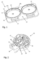
- FIG. 2 shows the rear or underside of a plug device element 20 shown, which are connected to the mounting plate shown in Figure 1 can.
- the essentially cylindrical connector element 20 has one - Insert 21 with electrical connecting parts, which is not of interest here on which is sleeve-shaped from a flange with an external thread is surrounded.
- the thread basically corresponds to that of known plug-in device elements provided external thread (for example series StarTOP 16A / 3p from Mennekes Elektrotechnik, Kirchhundem), making it a Screw together with an associated cover housing in a known manner allowed.
- the thread is after a first section 26 by one Missing piece 25 is interrupted before continuing through another section 24 becomes.
- the further section 24 is in the area due to a second missing piece a hinged lid connection 23 interrupted and divided into two parts. This optional interruption has the primary purpose of installing a protective conductor to enable according to French standard.
- the angular range over which the first missing piece 25 extends at least corresponds to the angular extent of the first section 18 of the mating thread on the mounting plate 10 of FIG. 1.
- the threaded portion 24 is in the second round by another missing piece 25 'interrupted, which is the same length as the first Missing piece 25 is and axially aligned with it.
- FIG. 2 on the underside of the hinged cover connection 23, which is used to attach a hinged lid (not shown) recognizable spring hook 22.
- the spring hook 22 snaps when the connection position is reached (Installation position) inside the base 13 of the hinged cover connection.
- the base 13 is the Hinged lid connection and / or the hinged lid connection 23 with a Provide side slit through which a screwdriver blade can be used if necessary Unlocking the spring hook 22 can be inserted.
- FIG. 3 shows a mounting plate 10 with a plug device socket already inserted 20 'in the installed position and a second connector socket 20, which is already inserted in the corresponding recess, but not yet in the end position is screwed.
- the second can 20 is fixed by rotating in the direction of the Arrow, whereby an angle of (360 ° - ⁇ ) is covered.
- the one Full rotation missing angle ⁇ is approximately 120 °. While screwing in a stroke of typically 2.5 mm is covered, which is approx. 45 ° before the end of the Rotation leads to an increasing torque, since one by about 0.5 mm raised ring seal in the mounting plate 10 (not shown) depressed must become. Due to the projecting hinged lid connection 23 is during Screwing movement of the box 20 given a good force application point.
- Figure 4 shows an exploded view of the connector system of Figure 3 after reaching the installation position through the box 20.
- the mounting thread on the can 20 and the mating thread on the mounting plate 10 in the Installation position a maximum coverage.
- the introduction of force is hereby evenly distributed over the entire circumference, which is important for a constant and even pressure on the captive arranged on the collar 12 Sealing ring (not shown) of the mounting plate 10.
- the mounting thread 120 has a thread line, which by a Interruption or a missing piece 125 in a short first Section 126 and a second section 124 is divided.
- the second Section 124 is also interrupted by another missing piece 125 ', which is the same length as the first missing piece 125 and is axially aligned with it.
- the counter thread 110 is about the first two thread revolutions in Essentially complementary to the mounting thread 120. With others Words are where the mounting thread 120 has missing pieces 125, 125 ', Formed sections 118, 118 'of the counter thread 110, and where Sections 126, 124 of the mounting thread 120 are formed, missing pieces 117, 117 'of the counter thread 110. From the third thread revolution, that is Mounting thread 120 and the counter thread 110 continuously formed.
- the mounting thread 120 could also be more than two axially aligned missing pieces 125, 125 'or the mating thread 110 more than two axially have aligned sections 116, 116 '.
- everyone could Thread revolutions must be provided with interruptions. The representation of Figure 5 is therefore only to be understood as an example.
- the two threads 110, 120 are joined together so that the first section 126 of the mounting thread 120 by the interruption 117 and possibly beyond also by the interruption 117 'in the first and second ones below Thread of the counter thread 110 arrives. Then the two Threads 110, 120 are screwed together. Even if it is up to Rotation angle covered by the end position is less than 360 ° "Leading" first section 126 reaches the maximum non-overlap Thread sections are smaller than that at a full rotation of 360 ° missing angles.
- the axial connection of the threads 110, 120 over several Thread revolutions has the advantage that accordingly many threads contribute to the hold. Furthermore, different thicknesses can be used Intermediate components between the connector element 20 and the mounting plate 10 can be accommodated.
Abstract
Description
Die Erfindung betrifft ein Steckvorrichtungselement mit einem Montagegewinde zur Verbindung mit einem anderen Bauteil. Ferner betrifft sie ein Steckvorrichtungssystem enthaltend mindestens ein Steckvorrichtungselement mit einem Montagegewinde sowie eine Montageplatte mit mindestens einer Ausnehmung für das Steckvorrichtungselement.The invention relates to a plug device element with an assembly thread for connection to another component. It also relates to a connector system containing at least one connector element a mounting thread and a mounting plate with at least one Recess for the connector element.
Steckvorrichtungen dienen dazu, eine leicht herzustellende sowie zu trennende Verbindung zwischen elektrischen Leitern bereitzustellen. Sie bestehen aus Steckern mit metallischen Kontaktstiften sowie Dosen (auch Buchsen genannt) mit metallischen Kontaktbuchsen, in welche die Kontaktstifte eingesteckt werden können. Aus dem Stand der Technik sind diesbezüglich Stecker und Dosen (nachfolgend allgemein als "Steckvorrichtungselemente" bezeichnet) mit einem Montagegewinde bekannt, auf das ein Abdeckgehäuse mit einer Kabeldurchführung aufgeschraubt werden kann.Plug devices are used to easily manufacture and separate To provide connection between electrical conductors. they consist of Plugs with metallic contact pins and sockets (also called sockets) with metallic contact sockets into which the contact pins are inserted can. In this regard, plugs and sockets are from the prior art (hereinafter generally referred to as "connector elements") with a Mounting thread known, on which a cover housing with a cable entry can be screwed on.
Des Weiteren ist es aus der DE 198 39 342 A1 bekannt, auf ein mehrgängiges, durch die Öffnung einer Montagewand geführtes Montagegewinde eines Steckvorrichtungselementes eine Überwurfmutter aufzuschrauben, um die Montagewand einzuklemmen und das Steckvorrichtungselement hierdruch an der Wand zu fixieren.Furthermore, it is known from DE 198 39 342 A1, to a multi-course, through the opening of a mounting wall mounting thread of a connector element unscrew a union nut around the mounting wall pinch and the plug device hereby on the wall fix.
Vor diesem Hintergrund war es Aufgabe der vorliegenden Erfindung, eine leichtere und schnellere Montage eines Steckvorrichtungselementes mit einem Montagegewinde insbesondere unter beengten Platzverhältnissen zu ermöglichen.Against this background, it was an object of the present invention to provide a lighter one and faster assembly of a connector element with an assembly thread to enable especially in confined spaces.
Diese Aufgabe wird durch ein Steckvorrichtungselement mit den Merkmalen des Anspruchs 1 sowie durch ein Steckvorrichtungssystem mit den Merkmalen des Anspruchs 2 gelöst. Vorteilhafte Ausgestaltungen sind in den Unteransprüchen enthalten.This task is achieved by a plug element with the characteristics of Claim 1 and a connector system with the features of Claim 2 solved. Advantageous configurations are in the subclaims contain.
Das erfindungsgemäße Steckvorrichtungselement weist ein Montagegewinde zur Verbindung mit einem anderen Bauteil wie beispielsweise einem Abdeckgehäuse oder einer Montageplatte auf. Das Montagegewinde kann sowohl ein Innengewinde als auch vorzugsweise ein Außengewinde sein. Das Montagegewinde beginnt mit einem nicht vollständig (d.h. um weniger als 360°) umlaufenden Abschnitt, der durch eine Unterbrechung vom nachfolgenden Abschnitt des Montagegewindes getrennt ist.The plug device element according to the invention has an assembly thread Connection with another component such as a cover housing or a mounting plate. The mounting thread can both be an internal thread and preferably also be an external thread. The mounting thread starts with an incomplete (i.e. less than 360 °) orbit Section that is interrupted by the subsequent section of the Assembly thread is separated.
Ein derartiges Montagegewinde kann mit einem korrespondierend bzw. komplementär ausgebildeten Gegengewinde in einer Schnellmontage durch weniger als eine Vollumdrehung von 360° in eine Verbindungsstellung zusammengeschraubt werden, wobei trotz der unvollständigen Umdrehung ein über den Umfang gleichmäßiger Kontakt mit ausgewogener Kraftverteilung erzielt werden kann. Letzteres ist z.B. für eine ordnungsgemäße Verpressung einer elastischen Dichtung zwischen dem Steckvorrichtungselement und dem weiteren Bauteil erforderlich. Durch die kurze Umdrehung um weniger als 360° kann das Steckvorrichtungselement auch unter beengten Platzverhältnissen montiert werden, bei denen keine Volldrehung für ein Einschrauben möglich ist. Hierdurch wird insbesondere das Einschrauben mehrerer eng benachbarter Steckvorrichtungselemente in die Ausnehmungen einer Montageplatte ermöglicht, ohne dass weitere Fixierungsmittel wie etwa eine von der Rückseite aufzuschraubende Überwurfmutter erforderlich wären.Such an assembly thread can be used with a corresponding or complementary trained counter thread in a quick assembly less than a full turn of 360 ° into a connection position be screwed together, despite the incomplete revolution Achieved even contact over the circumference with balanced force distribution can be. The latter is e.g. for a proper pressing of a elastic seal between the plug element and the other Component required. Due to the short turn of less than 360 ° this can be done Plug device element also installed in confined spaces in which no full rotation for screwing in is possible. hereby especially screwing in several closely adjacent connector elements allows in the recesses of a mounting plate without that further fixation means such as one to be screwed on from the back Union nut would be required.
Die Verwendung des Montagegewindes am Steckvorrichtungselement hat den weiteren Vorteil, dass dieses auch in herkömmlicher Weise mit einem "normalen" Gewinde zusammengeschraubt werden kann. Daher kann das Steckvorrichtungselement ohne konstruktive Änderung zum Beispiel je nach Bedarf mit einem herkömmlichen Abdeckgehäuse verbunden werden, bei welchem mehrere Umdrehungen möglich beziehungsweise erforderlich sind, oder mit einer Montageplatte, bei welcher aus Platzgründen für das Einschrauben weniger als eine Vollumdrehung zur Verfügung steht.The use of the mounting thread on the connector element has the further advantage that this can also be used in the conventional way with a "normal" Thread can be screwed together. Therefore, the connector element without a design change, for example with one as needed conventional cover housing are connected, in which several Revolutions are possible or necessary, or with a mounting plate, in which, for reasons of space, less than one for screwing in Full rotation is available.
Gemäß einer bevorzugten Weiterbildung des Steckvorrichtungselementes weist das Montagegewinde weitere Unterbrechungen auf, die mit der ersten, im Anschluss an den ersten Gewindeabschnitt liegenden Unterbrechung in axialer Richtung fluchten. In diesem Falle kann das Montagegewinde mit einem korrespondierenden Gegengewinde zunächst über ein oder mehrere Gewindegänge hinweg zusammengesteckt werden, bevor die Verschrau bung der Gewinde beginnt. Dies hat den Vorteil, dass mehrere Gewindegänge gleichzeitig zum Halt beitragen und dass gegebenenfalls unterschiedlich dicke Zwischenbauteile zwischen dem Steckvorrichtungselement und dem damit verbundenen weiteren Bauteil untergebracht werden können.According to a preferred development of the plug device element the mounting thread further interruptions, which with the first, in Connection to the first thread section lying in the axial interruption Align direction. In this case, the mounting thread can be used with a Corresponding counter-threads first over one or more threads be plugged together before screwing the thread starts. This has the advantage that several threads turn to hold at the same time contribute and that, if necessary, intermediate components of different thicknesses between the plug element and the associated further Component can be accommodated.
Weitere Erläuterungen zur Funktion des Montagegewindes mit Unterbrechungen sind in der Figurenbeschreibung zu finden.Further explanations on the function of the assembly thread with interruptions can be found in the description of the figures.
Die Erfindung betrifft ferner ein Steckvorrichtungssystem enthaltend mindestens ein Steckvorrichtungselement mit einem Montagegewinde sowie eine Montageplatte mit mindestens einer Ausnehmung für das Steckvorrichtungselement. Der Begriff der "Montageplatte" ist dabei in einem weiten Sinne zu verstehen und umfasst jedes Bauelement, welches in einem Bereich um den Anbringungsort eines Steckvorrichtungselementes herum im Wesentlichen eben ist. In diesem Sinne kann eine Montageplatte z.B. die mit Ausnehmungen versehene Wand eines Gerätegehäuses sein. Vorzugsweise ist die Montageplatte insgesamt eben und zum Beispiel rechteckig geformt. Das Steckvorrichtungssystem ist dadurch gekennzeichnet, dass
- die Ausnehmung in der Montageplatte ein zum Montagegewinde des Steckvorrichtungselementes korrespondierendes Gegengewinde aufweist, so dass das Steckvorrichtungselement unmittelbar an der Montageplatte festgeschraubt werden kann;
- das Montagegewinde am Steckvorrichtungselement und das Gegengewinde an der Montageplatte durch weniger als eine Vollumdrehung in eine Verbindungsstellung verschraubt werden können, so dass einerseits eine Schnellmontage sowie andererseits eine Anwendung unter beengten Platzverhältnissen möglich ist;
- in der Verbindungsstellung von Steckvorrichtungselement und Montageplatte der maximale Winkel, über welchen kein Kontakt zwischen Montagegewinde und Gegengewinde besteht, weniger als der an einer Vollumdrehung fehlende Winkel beträgt.
- the recess in the mounting plate has a mating thread corresponding to the mounting thread of the plug device element, so that the plug device element can be screwed directly onto the mounting plate;
- the mounting thread on the plug device element and the mating thread on the mounting plate can be screwed into a connecting position by less than one full turn, so that on the one hand quick assembly and on the other hand use in confined spaces is possible;
- in the connecting position of the plug device element and the mounting plate, the maximum angle, over which there is no contact between the mounting thread and the counter thread, is less than the angle missing from a full turn.
Das erfindungsgemäße Steckvorrichtungssystem hat den Vorteil, dass eine Schnellmontage von Steckvorrichtungselementen durch einfaches Einschrauben in die Ausnehmungen der Montageplatte möglich ist. Dabei können mehrere Steckvorrichtungselemente auch dann in üblicher Weise dicht nebeneinander auf der Montageplatte angeordnet werden, wenn aufgrund überstehender Ansätze der Steckvorrichtungselemente keine Vollumdrehung möglich ist.The plug device system according to the invention has the advantage that a Quick assembly of connector elements by simply screwing them in is possible in the recesses of the mounting plate. Several can Plug device elements then also close together in the usual way the mounting plate can be arranged if due to protruding approaches Plug device elements no full rotation is possible.
Wenn zwei herkömmliche Gewinde um weniger als eine Vollumdrehung miteinander verschraubt werden, liegen sie nur auf einer dem Drehwinkel entsprechenden Länge von 360°-α (mit 0 < α < 360°) aneinander an, während über den durchgehenden Restwinkel α hinweg kein Kontakt zwischen den verschraubten Teilen besteht. Dies führt zu einer ungleichmäßigen Verteilung der Kräfte und daher zu einer schlechten mechanischen Kopplung der Bauteile. Eine derartige Verbindung zwischen einem Steckvorrichtungselement und einem anderen Bauteil wird daher inakzeptabel, wenn der Restwinkel α eine bestimmte Größe (typischerweise 30°) überschreitet. In diesem Falle ist z.B. auch die gleichmäßige Verpressung von Dichtungsringen nicht mehr gewährleistet. Derartige Probleme werden bei dem erfindungsgemäßen Steckvorrichtungssystem vermieden, da hierbei das Montagegewinde und das Gegengewinde so ausgebildet sind, dass der Winkelbereich, über den kein Kontakt zwischen dem Steckvorrichtungselement und seinem Gegenstück besteht, kleiner als der an einer Vollumdrehung fehlende Restwinkel α ist. Selbst wenn daher der Restwinkel α eine erhebliche Größe von zum Beispiel 120° aufweist, kann auf diese Weise eine gute Bauteilverbindung mit gleichmäßiger Kräfteverteilung gewährleistet werden.If two conventional threads less than a full turn are screwed together, they only lie on one the angle of rotation corresponding length of 360 ° -α (with 0 <α <360 °) to each other while no contact between the screwed parts. This leads to an uneven distribution of the Forces and therefore poor mechanical coupling of the components. A such connection between a connector element and a other component is therefore unacceptable if the residual angle α a certain Size (typically 30 °). In this case e.g. also the uniform pressing of sealing rings is no longer guaranteed. Such problems arise with the connector system according to the invention avoided, because the mounting thread and the counter thread are formed that the angular range over which there is no contact between the Plug device element and its counterpart is smaller than that one full revolution is missing residual angle α. Therefore, even if the Residual angle α has a considerable size of, for example, 120 ° this way a good component connection with even force distribution be guaranteed.
Ein Steckvorrichtungssystem mit den beschriebenen Eigenschaften kann auf verschiedene Weise realisiert werden. Gemäß einer ersten Ausführungsform ist das Steckvorrichtungselement in der oben erläuterten Weise ausgebildet, d.h. sein Montagegewinde beginnt mit einem nicht vollständig umlaufenden Abschnitt, der durch eine Unterbrechung vom nachfolgenden Abschnitt des Montagegewindes getrennt ist. Das korrespondierende Gegengewinde weist ebenfalls nach einem ersten Abschnitt eine Unterbrechung auf, wobei die Dimensionierung der Gewinde so abgestimmt ist, dass der erste Abschnitt des einen Gewindes jeweils durch die Unterbrechung des anderen Gewindes geführt werden kann. Für eine detailliertere Erläuterung des Zusammenwirkens derartiger Gewinde sei auf die Figurenbeschreibung verwiesen.A connector system with the described properties can be used can be realized in different ways. According to a first embodiment the connector element is formed in the manner explained above, i.e. his The mounting thread begins with a section that does not run all the way round by an interruption from the following section of the assembly thread is separated. The corresponding mating thread also shows one first section an interruption, the dimensioning of the thread is coordinated so that the first section of the one thread in each case through the Interruption of the other thread can be performed. For a more detailed Explanation of the interaction of such threads is on the description of the figures directed.
Die gewünschten Verschraubungseigenschaften werden ferner durch ein Montagegewinde und eine Gegengewinde erreicht, welche mehrgängig ausgebildet sind. Bei mehrgängigen Gewinden verläuft definitionsgemäß mehr als eine Gewindelinie schraubenförmig um den Gewindeschaft. Durch die Mehrgängigkeit wird eine große axiale Steigung jeder einzelnen Gewindelinie erreicht, so dass schon durch eine kurze Umdrehung um 360°-α ein großer axialer Weg zurückgelegt werden kann, der zum Beispiel zum Verpressen einer Dichtung ausreicht. Gleichzeitig wird durch die versetzt zueinander beginnenden einzelnen Gewindelinien erreicht, dass in der Verbindungsstellung die jeweiligen Winkelbereiche von 360°-α, über welche die Gewindelinien aneinander anliegen, ebenfalls zueinander versetzt sind. Daher ist der Winkelbereich, über welchen kein Kontakt zwischen den miteinander verschraubten Teilen besteht, in jedem Falle kleiner als α. Wenn der Winkelversatz zwischen zwei benachbarten Gewindelinien kleiner ist als der Einschraubwinkel 360°-α, ist sogar sichergestellt, dass über den gesamten Umfangsbereich von 360° immer mindestens eine Gewindelinie von Montagegewinde und Gegengewinde zueinander in Kontakt stehen. The desired bolting properties are also indicated by a Mounting thread and a counter thread, which is multi-start are trained. With multi-start threads, by definition, more than runs a thread line helically around the threaded shaft. Through the Multi-threading becomes a large axial pitch of each individual thread line reached, so that even a short rotation through 360 ° -α a large axial Can be covered, for example for pressing a seal sufficient. At the same time, the individual begins offset from one another Thread lines achieved that in the connection position the respective Angular ranges of 360 ° -α over which the thread lines abut each other, are also offset from one another. Hence the angular range over which no In any case, there is contact between the screwed parts smaller than α. If the angular misalignment between two adjacent thread lines is smaller than the screw-in angle 360 ° -α, it is even ensured that over the entire circumferential area of 360 ° always at least one thread line of The mounting thread and counter thread are in contact with each other.
Optional sind die Ausnehmungen der Montageplatte von einem Kragen umgeben, wobei in dem Kragen das korrespondierende Gegengewinde ausgebildet ist. Der Kragen sorgt für eine ausreichende Höhe zur Aufnahme des Montage gewindes und kann nach einer oder nach beiden Seiten der Montageplatte überstehen. Falls der Kragen hoch steht, wird ferner für einen Abstand zwischen der Oberfläche der Montageplatte und dem einzuschraubenden Steckvorrichtungselement gesorgt, welcher Kollisionen mit eventuellen Vorsprüngen an der Montageplatte verhindert.The recesses of the mounting plate are optionally surrounded by a collar, wherein the corresponding counter thread is formed in the collar. The Collar provides sufficient height to accommodate the mounting thread and can protrude on one or both sides of the mounting plate. If the collar is high, is also for a distance between the surface of the Mounting plate and the plug-in element to be screwed in, which prevents collisions with any protrusions on the mounting plate.
Gemäß einer Weiterbildung des Steckvorrichtungssystems weist dieses Verriegelungsmittel auf, durch welche die Verbindungsstellung gegen eine Verdrehung blockiert wird. Durch die Verriegelungsmittel kann somit eine eindeutige Endposition der Verschraubung definiert und gegen ein unbeabsichtigtes Lösen gesichert werden. Für die Ausgestaltung der Verriegelungsmittel stehen dem Fachmann dabei verschiedene Möglichkeiten zur Verfügung. Insbesondere können die Verriegelungsmittel als ein radial und/oder axial federnd überstehender Vorsprung ausgebildet sein, welcher in eine korrespondierende Ausnehmung am anderen Teil einrastet. Je nach Anwendungsfall kann das Verriegelungsmittel dabei so ausgestaltet sein, dass es leicht von Hand, nur mit einem Werkzeug oder nur unter Zerstörung entriegelbar ist.According to a development of the plug device system, this has Locking means through which the connection position against a Twisting is blocked. The locking means can thus Clear end position of the screw connection defined and against unintentional loosening can be secured. For the design of the Locking means are available to the person skilled in the art in various ways Available. In particular, the locking means as a radial and / or axially resiliently projecting projection be formed, which in a corresponding Recess clicks into the other part. Depending on the application the locking means can be designed in such a way that it can be easily can only be unlocked with a tool or only with destruction.
Vorzugsweise ist entlang der Ausnehmung der Montageplatte ein unverlierbares Dichtungselement angeordnet, welches nach Erreichen der Einbaulage des Steckvorrichtungselementes dessen Verbindung zur Montageplatte wasserdicht schließt. Das Dichtungselement kann z.B. ein O-Ring aus einem elastischen Material sein, der in einer Nut am Kragen der Montageplatte angeordnet oder vorzugsweise dort integral angeformt ist.Preferably, a captive is along the recess of the mounting plate Sealing element arranged, which after reaching the installation position of the plug device element its connection to the mounting plate is watertight closes. The sealing element can e.g. an o-ring made of an elastic Material that is arranged in a groove on the collar of the mounting plate or is preferably integrally formed there.
Im Folgenden wird die Erfindung mit Hilfe der Figuren beispielhaft erläutert. Es zeigt:
- Fig. 1
- eine perspektivische Aufsicht einer Montageplatte mit zwei Ausnehmungen für Steckvorrichtungselemente;
- Fig. 2
- eine perspektivische Unteransicht eines Steckvorrichtungselementes mit einem Montagegewinde;
- Fig. 3
- eine perspektivische Aufsicht auf eine Montageplatte mit einem Steckvorrichtungselement in Einbaustellung und einem weiteren Steckvorrichtungselement zu Beginn des Einschraubens;
- Fig. 4
- eine perspektivische Explosionsdarstellung des in Einbaustellung überführten Steckvorrichtungselementes von Figur 3 von unten;
- Fig. 5
- eine schematische Darstellung eines abgewickelten Montagegewindes 120 und eines hierzu korrespondierenden Gegengewindes 110.
- Fig. 1
- a top perspective view of a mounting plate with two recesses for connector elements;
- Fig. 2
- a bottom perspective view of a connector element with a mounting thread;
- Fig. 3
- a perspective view of a mounting plate with a connector element in the installed position and a further connector element at the beginning of the screwing;
- Fig. 4
- 3 shows an exploded perspective view of the plug device element from FIG. 3, which has been brought into the installed position;
- Fig. 5
- a schematic representation of a developed mounting
thread 120 and acorresponding counter thread 110.
In Figur 1 ist eine perspektivische Ansicht auf die Oberseite einer Montageplatte
10 aus Kunststoff dargestellt, welche zur Schnellmontage zweier Steckvorrichtungselemente
eingerichtet ist. Die Montageplatte 10 weist hierzu einen
flachen, in etwa rechteckigen Trägerkörper 11 mit zwei kreisförmigen
Ausnehmungen 19a, 19b auf. Die Ausnehmungen 19a, 19b sind jeweils von
einem an der Außenseite der Montageplatte 10 nach oben abstehenden
Kragen 12 umgeben, welcher angesichts der verhältnismäßig dünnen Montageplatte
10 für eine ausreichende Höhe zur Aufnahme des Gegen gewindes sowie für
einen Abstand von der Ebene des Trägerkörpers 11 sorgt.In Figure 1 is a perspective view of the top of a mounting
An der Innenfläche der Kragen 12 ist jeweils ein (Gegen-)Gewinde mit einem
einzigen unterbrochenen und teilweise höhenversetzten Gewindegang
ausgebildet, der durch ein einfaches Zweibacken-Werkzeug geformt werden kann.
Dieser einzige Gewindegang besteht aus einem ersten Abschnitt 18, welcher sich
über einen kleinen Winkelbereich von typischerweise 10° bis 30° erstreckt. Im
Anschluss an den ersten Abschnitt 18 ist das Gewinde durch eine Unterbrechung
beziehungsweise ein Fehlstück 17a unterbrochen. Das Fehlstück 17a erstreckt
sich ebenfalls über einen verhältnismäßig kleinen Winkelbereich von
typischerweise 10° bis 30°. Im Anschluss an die Unterbrechung 17a folgt ein
zweiter, längerer Abschnitt 16 des Gewindes, welcher sich über einen Bereich von
typischerweise 220° ± 40° erstreckt. Zwischen dem Ende des zweiten
Gewindeabschnittes 16 und dem Beginn des ersten Gewindeabschnittes 18 liegt
wiederum eine Unterbrechung 17b ohne jegliches Gewi nde.On the inner surface of the
Wie in Figur 1 ferner zu erkennen ist, ist der Kragen 12 an einer Längsseite der
Montageplatte 10 durch einen rechtwinkligen Rahmen 13 erweitert, welcher als
Sockel für die Klappdeckelanbindung 23 (Figur 2) eines Steckvorrichtungselementes
20 dient.As can also be seen in FIG. 1, the
In Figur 2 ist die Rück- bzw. Unterseite eines Steckvorrichtungselementes 20
dargestellt, welches mit der in Figur 1 gezeigten Montageplatte verbunden werden
kann. Das im Wesentlichen zylindrische Steckvorrichtungselement 20 weist einen
- vorliegend nicht näher interessierenden - Einsatz 21 mit elektrischen Anschlussteilen
auf, welcher hülsenförmig von einem Flansch mit einem Außengewinde
umgeben ist. Das Gewinde entspricht grundsätzlich einem bei bekannten Steckvorrichtungselementen
vorgesehenen Außengewinde (zum Beispiel Serie
StarTOP 16A/3p von Mennekes Elektrotechnik, Kirchhundem), so dass es ein
Zusammenschrauben mit einem zugehörigen Abdeckgehäuse in bekannter Weise
erlaubt.FIG. 2 shows the rear or underside of a
Um darüber hinaus eine Schnellmontage in einer Montageplatte gemäß Figur 1 zu
ermöglichen, ist das Gewinde nach einem ersten Abschnitt 26 durch ein
Fehlstück 25 unterbrochen, bevor es durch einen weiteren Abschnitt 24 fortgesetzt
wird. Der weitere Abschnitt 24 ist dabei durch ein zweites Fehlstück im Bereich
einer Klappdeckelanbindung 23 unterbrochen und in zwei Teile unterteilt. Diese
optionale Unterbrechung hat vorrangig den Zweck, einen Schutzleitereinbau
gemäß französischen Standard zu ermöglichen. Der Winkelbereich, über den sich
das erste Fehlstück 25 erstreckt, entspricht mindestens der Winkelerstreckung des
ersten Abschnittes 18 des Gegengewindes an der Montageplatte 10 von Figur 1.
Schließlich ist der Gewindeabschnitt 24 im zweiten Umlauf noch einmal durch ein
weiteres Fehlstück 25' unterbrochen, welches gleich lang wie das erste
Fehlstück 25 ist und axial mit diesem fluchtet.In addition to rapid assembly in a mounting plate according to FIG
allow, the thread is after a
Des Weiteren ist in Figur 2 an der Unterseite der Klappdeckelanbindung 23,
welche der Anbringung eines Klappdeckels (nicht dargestellt) dient, ein
vorstehender Federhaken 22 zu erkennen. Beim Einschrauben des Steckvorrichtungselementes
20 in eine Ausnehmung 19a, 19b der Montageplatte 10
von Figur 1 rastet der Federhaken 22 bei Erreichen der Verbindungsstellung
(Einbaulage) im Inneren des Sockels 13 der Klappdeckelanbindung ein. Durch
diese Rastverbindung wird ein ungewolltes Zurückdrehen verhindert und somit
eine Demontagesicherung erreicht. Vorzugsweise ist der Sockel 13 der
Klappdeckelanbindung und/oder die Klappdeckelanbindung 23 mit einem
Seitenschlitz versehen, durch welchen bei Bedarf eine Schraubenzieherklinge zur
Entriegelung des Federhakens 22 eingesteckt werden kann.Furthermore, in FIG. 2 on the underside of the hinged
Figur 3 zeigt eine Montageplatte 10 mit einer fertig eingesetzten Steckvorrichtungsdose
20' in Einbaulage sowie einer zweiten Steckvorrichtungsdose 20,
welche bereits in die zugehörige Ausnehmung eingesteckt, jedoch noch nicht in
die Endposition geschraubt ist. Durch den Anschlag der Klappdeckel anbindung 23
an der bereits montierten Dose 20' kann die korrekte Ausrichtung der zweiten
Dose 20 beim Einstecken quasi blind gefunden werden. Aufgrund des Anschlags
der Klappdeckelanbindung 23 an der Dose 20' ist es nicht möglich, die zweite
Dose 20 durch ein oder mehrere Vollumdrehungen an der Montageplatte 10 festzuschrauben.FIG. 3 shows a mounting
Die Fixierung der zweiten Dose 20 erfolgt durch eine Drehung in Richtung des
Pfeils, wobei ein Winkel von (360° - α) zurückgelegt wird. Der an einer
Vollumdrehung fehlende Winkel α beträgt ca. 120°. Während des Einschraubens
wird ein Hub von typischerweise 2.5 mm zurückgelegt, der ca. 45° vor Ende der
Drehung zu einem ansteigenden Drehmoment führt, da eine um etwa 0.5 mm
erhabene Ringdichtung in der Montageplatte 10 (nicht dargestellt) niedergedrückt
werden muss. Durch die vorspringende Klappdeckelanbindung 23 ist während der
Einschraubbewegung der Dose 20 ein guter Kraftangriffspunkt gegeben.The
Figur 4 zeigt eine Explosionsdarstellung des Steckvorrichtungssystems von
Figur 3 nach Erreichen der Einbaulage durch die Dose 20. Das Montagegewinde
an der Dose 20 sowie das Gegengewinde an der Montageplatte 10 haben in der
Einbaulage eine maximale Überdeckung. Die Krafteinleitung ist hierdurch
gleichmäßig auf den gesamten Umfang verteilt, was wichtig für einen konstanten
und gleichmäßigen Druck auf den unverlierbar am Kragen 12 angeordneten
Dichtring (nicht dargestellt) der Montageplatte 10 ist.Figure 4 shows an exploded view of the connector system of
Figure 3 after reaching the installation position through the
In Figur 5 ist in einer schematischen Darstellung das Zusammenwirken von
korrespondierenden Gewindeunterbrechungen dargestellt. Im oberen Teil der
Figur ist ein abgewickeltes erstes Gewinde 120, bei dem es sich z.B. um das
Montagegewinde handeln kann, und im unteren Teil das hierzu korrespondierende
zweite Gewinde 110 (Gegengewinde) dargestellt. Hilfslinien sind dabei gestrichelt
und Gewindelinien durchgezogen gezeichnet.In Figure 5, the interaction of
corresponding thread interruptions are shown. In the upper part of the
Figure is an unwound
Das Montagegewinde 120 weist eine Gewindelinie auf, welche durch eine
Unterbrechung beziehungsweise ein Fehlstück 125 in einen kurzen ersten
Abschnitt 126 und einen zweiten Abschnitt 124 unterteilt ist. Der zweite
Abschnitt 124 ist darüber hinaus durch ein weiteres Fehlstück 125' unterbrochen,
welches gleich lang wie das erste Fehlstück 125 ist und mit diesem axial fluchtet.The mounting
Das Gegengewinde 110 ist über die ersten zwei Gewindeumläufe im
Wesentlichen komplementär zum Montagegewinde 120 ausgebildet. Mit anderen
Worten sind dort, wo das Montagegewinde 120 Fehlstücke 125, 125' hat,
Abschnitte 118, 118' des Gegengewindes 110 ausgebildet, und dort, wo
Abschnitte 126, 124 des Montagegewindes 120 ausgebildet sind, Fehlstücke 117,
117' des Gegengewindes 110 liegen. Ab dem dritten Gewindeumlauf sind das
Montagegewinde 120 und das Gegengewinde 110 durchgehend ausgebildet.
Selbstverständlich könnte das Montagegewinde 120 auch mehr als zwei axial
fluchtende Fehlstücke 125, 125' bzw. das Gegengewinde 110 mehr als zwei axial
fluchtende Abschnitte 116, 116' aufweisen. Insbesondere könnten alle
Gewindeumläufe mit Unterbrechungen versehen sein. Die Darstellung von Figur 5
ist daher nur als Beispiel zu verstehen.The
Durch axiales Zusammenstecken in Pfeilrichtung können die beiden Gewinde 110,
120 so zusammengefügt werden, dass der erste Abschnitt 126 des Montagegewindes
120 durch die Unterbrechung 117 und gegebenenfalls darüber hinaus
auch durch die Unterbrechung 117' in den ersten bzw. zweiten darunter gelegenen
Gewindegang des Gegengewindes 110 gelangt. Anschließend können die beiden
Gewinde 110, 120 miteinander verschraubt werden. Auch wenn der dabei bis zur
Endstellung zurückgelegte Drehwinkel weniger als 360° beträgt, wird durch den
"vorauseilenden" ersten Abschnitt 126 erreicht, dass die maximalen überlappungsfreien
Gewindeabschnitte kleiner sind als der an einer Volldrehung von 360° noch
fehlende Winkel.By axially plugging together in the direction of the arrow, the two
Das axiale Zusammenstecken der Gewinde 110, 120 über mehrere
Gewindeumläufe (in Figur 5 maximal zwei) hat den Vorteil, dass entsprechend
viele Gewindegänge zum Halt beitragen. Ferner können unterschiedlich dicke
Zwischenbauteile zwischen dem Steckvorrichtungselement 20 und der Montageplatte
10 untergebracht werden.The axial connection of the
Claims (8)
dadurch gekennzeichnet, dass das Montagegewinde (120) mit einem nicht vollständig umlaufenden Abschnitt (26, 126) beginnt, der durch eine Unterbrechung (25, 125) vom nachfolgenden Abschnitt (24, 124) des Montagegewindes getrennt ist.Plug device element (20) with an assembly thread for connection to another component (10),
characterized in that the mounting thread (120) begins with a not completely circumferential section (26, 126) which is separated by an interruption (25, 125) from the subsequent section (24, 124) of the mounting thread.
dadurch gekennzeichnet, dass
characterized in that
dadurch gekennzeichnet, dass es ein Steckvorrichtungselement (20) nach Anspruch 1 oder 2 enthält und dass das korrespondierende Gegengewinde (16, 18, 110) mindestens eine Unterbrechung (17a, 117, 117') aufweist.Plug device system according to claim 3,
characterized in that it contains a plug device element (20) according to claim 1 or 2 and that the corresponding mating thread (16, 18, 110) has at least one interruption (17a, 117, 117 ').
dadurch gekennzeichnet, dass das Montagegewinde und das Gegengewinde mehrgängig ausgebildet sind.Plug device system according to claim 3 or 4,
characterized in that the mounting thread and the counter thread are multi-start.
dadurch gekennzeichnet, dass die Ausnehmungen (19a, 19b) der Montageplatte (10) von einem Kragen (12) umgeben sind, in welchem das korrespondierende Gegengewinde (16, 18) ausgebildet ist.Plug device system according to at least one of claims 3 to 5,
characterized in that the recesses (19a, 19b) of the mounting plate (10) are surrounded by a collar (12) in which the corresponding mating thread (16, 18) is formed.
dadurch gekennzeichnet, dass es Verriegelungsmittel (13, 22) aufweist zur Blockierung der Verbindungsstellung gegen Verdrehung.Plug device system according to at least one of claims 3 to 6,
characterized in that it has locking means (13, 22) for blocking the connection position against rotation.
dadurch gekennzeichnet, dass entlang der Ausnehmung (19a, 19b) der Montageplatte (10) ein unverlierbares Dichtungselement angeordnet ist.Plug device system according to at least one of claims 3 to 7,
characterized in that a captive sealing element is arranged along the recess (19a, 19b) of the mounting plate (10).
Applications Claiming Priority (3)
| Application Number | Priority Date | Filing Date | Title |
|---|---|---|---|
| DE2003101879 DE10301879B3 (en) | 2003-01-17 | 2003-01-17 | Electrical plug socket element with external fixing thread for securing to mounting plate by partial rotation through less than 360 degrees |
| DE10301879 | 2003-01-17 | ||
| EP03028863 | 2003-12-16 |
Related Parent Applications (1)
| Application Number | Title | Priority Date | Filing Date |
|---|---|---|---|
| EP03028863 Division | 2003-01-17 | 2003-12-16 |
Publications (2)
| Publication Number | Publication Date |
|---|---|
| EP1473806A2 true EP1473806A2 (en) | 2004-11-03 |
| EP1473806A3 EP1473806A3 (en) | 2005-06-29 |
Family
ID=32991916
Family Applications (1)
| Application Number | Title | Priority Date | Filing Date |
|---|---|---|---|
| EP04102329A Withdrawn EP1473806A3 (en) | 2003-01-17 | 2003-12-16 | Connecting device with a mounting thread |
Country Status (1)
| Country | Link |
|---|---|
| EP (1) | EP1473806A3 (en) |
Cited By (2)
| Publication number | Priority date | Publication date | Assignee | Title |
|---|---|---|---|---|
| EP1923966A2 (en) * | 2006-11-14 | 2008-05-21 | ERICH JAEGER GmbH & Co. KG | Socket |
| EP1688656B1 (en) * | 2005-02-02 | 2012-12-19 | Truma Gerätetechnik GmbH & Co. KG | Quick-acting connection system for threaded connections |
Citations (3)
| Publication number | Priority date | Publication date | Assignee | Title |
|---|---|---|---|---|
| US5564937A (en) * | 1994-12-21 | 1996-10-15 | Illinois Tool Works Inc. | Light bulb socket assembly |
| DE10045263A1 (en) * | 2000-09-13 | 2002-03-28 | Itt Mfg Enterprises Inc | Plug connector element for use in an appliance plug connection has a casing to hold sleeve contacts securely on axis with their rear end having a pocket hole drilled for inserting a single-wire cable with a sealing element. |
| EP1249899A2 (en) * | 2001-04-12 | 2002-10-16 | PC Electric Ges.m.b.H. | Flange portion |
-
2003
- 2003-12-16 EP EP04102329A patent/EP1473806A3/en not_active Withdrawn
Patent Citations (3)
| Publication number | Priority date | Publication date | Assignee | Title |
|---|---|---|---|---|
| US5564937A (en) * | 1994-12-21 | 1996-10-15 | Illinois Tool Works Inc. | Light bulb socket assembly |
| DE10045263A1 (en) * | 2000-09-13 | 2002-03-28 | Itt Mfg Enterprises Inc | Plug connector element for use in an appliance plug connection has a casing to hold sleeve contacts securely on axis with their rear end having a pocket hole drilled for inserting a single-wire cable with a sealing element. |
| EP1249899A2 (en) * | 2001-04-12 | 2002-10-16 | PC Electric Ges.m.b.H. | Flange portion |
Cited By (3)
| Publication number | Priority date | Publication date | Assignee | Title |
|---|---|---|---|---|
| EP1688656B1 (en) * | 2005-02-02 | 2012-12-19 | Truma Gerätetechnik GmbH & Co. KG | Quick-acting connection system for threaded connections |
| EP1923966A2 (en) * | 2006-11-14 | 2008-05-21 | ERICH JAEGER GmbH & Co. KG | Socket |
| EP1923966A3 (en) * | 2006-11-14 | 2010-10-20 | ERICH JAEGER GmbH + Co. KG | Socket |
Also Published As
| Publication number | Publication date |
|---|---|
| EP1473806A3 (en) | 2005-06-29 |
Similar Documents
| Publication | Publication Date | Title |
|---|---|---|
| EP1891710A1 (en) | Electrical plug-in connection, plug part, and socket part | |
| EP0694988A2 (en) | Cable terminal with mounting device | |
| EP1709711B1 (en) | Device for connecting a coaxial cable to a housing | |
| WO2018210892A1 (en) | Cable bushing | |
| AT523016B1 (en) | connector | |
| EP2434586A1 (en) | Electrical connector with a union nut | |
| EP3292603B1 (en) | Cable/lead insertion unit | |
| DE102005059383A1 (en) | Device for compensating for differences in length between a cylinder lock and a door leaf | |
| WO2018153661A1 (en) | Plug coupling with strain relief for a connecting cable | |
| EP2240987B1 (en) | Plug-in device | |
| WO2017182028A1 (en) | Securing assembly for securing a flange plate to an electrical enclosure housing, and a corresponding electrical enclosure housing | |
| EP3688851B1 (en) | Cable screw connection | |
| DE3517933C2 (en) | Lock mechanism with a pawl shaft | |
| WO2013034350A1 (en) | Electrical switchgear unit | |
| DE10301879B3 (en) | Electrical plug socket element with external fixing thread for securing to mounting plate by partial rotation through less than 360 degrees | |
| EP0272199B1 (en) | Cable ducting with at least one aluminium ducting section and a connecting piece for a protection conductor | |
| EP1473806A2 (en) | Connecting device with a mounting thread | |
| EP2750269A1 (en) | Pump power unit | |
| DE10206063B4 (en) | Add-on plug-in device | |
| DE102008057473B4 (en) | Grommet | |
| EP1318575B1 (en) | Mountable plug-in connector device | |
| DE202019101084U1 (en) | connecting device | |
| EP2802040B1 (en) | Electronic device | |
| DE102011076210B4 (en) | Mounting arrangement for two adjacent sanitary fittings | |
| EP3435497B1 (en) | Mounting aid means for producing a screw connection between an electric plug or bushing part and a connecting part |
Legal Events
| Date | Code | Title | Description |
|---|---|---|---|
| PUAI | Public reference made under article 153(3) epc to a published international application that has entered the european phase |
Free format text: ORIGINAL CODE: 0009012 |
|
| AK | Designated contracting states |
Kind code of ref document: A2 Designated state(s): AT BE BG CH CY CZ DE DK EE ES FI FR GB GR HU IE IT LI LU MC NL PT RO SE SI SK TR |
|
| AX | Request for extension of the european patent |
Extension state: AL LT LV MK |
|
| PUAL | Search report despatched |
Free format text: ORIGINAL CODE: 0009013 |
|
| AK | Designated contracting states |
Kind code of ref document: A3 Designated state(s): AT BE BG CH CY CZ DE DK EE ES FI FR GB GR HU IE IT LI LU MC NL PT RO SE SI SK TR |
|
| AX | Request for extension of the european patent |
Extension state: AL LT LV MK |
|
| 17P | Request for examination filed |
Effective date: 20050701 |
|
| AKX | Designation fees paid | ||
| STAA | Information on the status of an ep patent application or granted ep patent |
Free format text: STATUS: THE APPLICATION IS DEEMED TO BE WITHDRAWN |
|
| 18D | Application deemed to be withdrawn |
Effective date: 20051230 |
|
| REG | Reference to a national code |
Ref country code: DE Ref legal event code: 8566 |