EP1473712A1 - Optical recording medium and method for recording information on optical recording medium - Google Patents
Optical recording medium and method for recording information on optical recording medium Download PDFInfo
- Publication number
- EP1473712A1 EP1473712A1 EP03703079A EP03703079A EP1473712A1 EP 1473712 A1 EP1473712 A1 EP 1473712A1 EP 03703079 A EP03703079 A EP 03703079A EP 03703079 A EP03703079 A EP 03703079A EP 1473712 A1 EP1473712 A1 EP 1473712A1
- Authority
- EP
- European Patent Office
- Prior art keywords
- recording
- rtop
- recording medium
- optical recording
- layer
- Prior art date
- Legal status (The legal status is an assumption and is not a legal conclusion. Google has not performed a legal analysis and makes no representation as to the accuracy of the status listed.)
- Withdrawn
Links
Images


Classifications
-
- G—PHYSICS
- G11—INFORMATION STORAGE
- G11B—INFORMATION STORAGE BASED ON RELATIVE MOVEMENT BETWEEN RECORD CARRIER AND TRANSDUCER
- G11B7/00—Recording or reproducing by optical means, e.g. recording using a thermal beam of optical radiation by modifying optical properties or the physical structure, reproducing using an optical beam at lower power by sensing optical properties; Record carriers therefor
- G11B7/24—Record carriers characterised by shape, structure or physical properties, or by the selection of the material
- G11B7/2403—Layers; Shape, structure or physical properties thereof
- G11B7/24035—Recording layers
-
- G—PHYSICS
- G11—INFORMATION STORAGE
- G11B—INFORMATION STORAGE BASED ON RELATIVE MOVEMENT BETWEEN RECORD CARRIER AND TRANSDUCER
- G11B7/00—Recording or reproducing by optical means, e.g. recording using a thermal beam of optical radiation by modifying optical properties or the physical structure, reproducing using an optical beam at lower power by sensing optical properties; Record carriers therefor
- G11B7/24—Record carriers characterised by shape, structure or physical properties, or by the selection of the material
- G11B7/241—Record carriers characterised by shape, structure or physical properties, or by the selection of the material characterised by the selection of the material
- G11B7/242—Record carriers characterised by shape, structure or physical properties, or by the selection of the material characterised by the selection of the material of recording layers
- G11B7/243—Record carriers characterised by shape, structure or physical properties, or by the selection of the material characterised by the selection of the material of recording layers comprising inorganic materials only, e.g. ablative layers
- G11B2007/24302—Metals or metalloids
- G11B2007/24306—Metals or metalloids transition metal elements of groups 3-10
-
- G—PHYSICS
- G11—INFORMATION STORAGE
- G11B—INFORMATION STORAGE BASED ON RELATIVE MOVEMENT BETWEEN RECORD CARRIER AND TRANSDUCER
- G11B7/00—Recording or reproducing by optical means, e.g. recording using a thermal beam of optical radiation by modifying optical properties or the physical structure, reproducing using an optical beam at lower power by sensing optical properties; Record carriers therefor
- G11B7/24—Record carriers characterised by shape, structure or physical properties, or by the selection of the material
- G11B7/241—Record carriers characterised by shape, structure or physical properties, or by the selection of the material characterised by the selection of the material
- G11B7/242—Record carriers characterised by shape, structure or physical properties, or by the selection of the material characterised by the selection of the material of recording layers
- G11B7/243—Record carriers characterised by shape, structure or physical properties, or by the selection of the material characterised by the selection of the material of recording layers comprising inorganic materials only, e.g. ablative layers
- G11B2007/24302—Metals or metalloids
- G11B2007/2431—Metals or metalloids group 13 elements (B, Al, Ga, In)
-
- G—PHYSICS
- G11—INFORMATION STORAGE
- G11B—INFORMATION STORAGE BASED ON RELATIVE MOVEMENT BETWEEN RECORD CARRIER AND TRANSDUCER
- G11B7/00—Recording or reproducing by optical means, e.g. recording using a thermal beam of optical radiation by modifying optical properties or the physical structure, reproducing using an optical beam at lower power by sensing optical properties; Record carriers therefor
- G11B7/24—Record carriers characterised by shape, structure or physical properties, or by the selection of the material
- G11B7/241—Record carriers characterised by shape, structure or physical properties, or by the selection of the material characterised by the selection of the material
- G11B7/242—Record carriers characterised by shape, structure or physical properties, or by the selection of the material characterised by the selection of the material of recording layers
- G11B7/243—Record carriers characterised by shape, structure or physical properties, or by the selection of the material characterised by the selection of the material of recording layers comprising inorganic materials only, e.g. ablative layers
- G11B2007/24302—Metals or metalloids
- G11B2007/24312—Metals or metalloids group 14 elements (e.g. Si, Ge, Sn)
-
- G—PHYSICS
- G11—INFORMATION STORAGE
- G11B—INFORMATION STORAGE BASED ON RELATIVE MOVEMENT BETWEEN RECORD CARRIER AND TRANSDUCER
- G11B7/00—Recording or reproducing by optical means, e.g. recording using a thermal beam of optical radiation by modifying optical properties or the physical structure, reproducing using an optical beam at lower power by sensing optical properties; Record carriers therefor
- G11B7/24—Record carriers characterised by shape, structure or physical properties, or by the selection of the material
- G11B7/241—Record carriers characterised by shape, structure or physical properties, or by the selection of the material characterised by the selection of the material
- G11B7/242—Record carriers characterised by shape, structure or physical properties, or by the selection of the material characterised by the selection of the material of recording layers
- G11B7/243—Record carriers characterised by shape, structure or physical properties, or by the selection of the material characterised by the selection of the material of recording layers comprising inorganic materials only, e.g. ablative layers
- G11B2007/24302—Metals or metalloids
- G11B2007/24314—Metals or metalloids group 15 elements (e.g. Sb, Bi)
-
- G—PHYSICS
- G11—INFORMATION STORAGE
- G11B—INFORMATION STORAGE BASED ON RELATIVE MOVEMENT BETWEEN RECORD CARRIER AND TRANSDUCER
- G11B7/00—Recording or reproducing by optical means, e.g. recording using a thermal beam of optical radiation by modifying optical properties or the physical structure, reproducing using an optical beam at lower power by sensing optical properties; Record carriers therefor
- G11B7/24—Record carriers characterised by shape, structure or physical properties, or by the selection of the material
- G11B7/241—Record carriers characterised by shape, structure or physical properties, or by the selection of the material characterised by the selection of the material
- G11B7/242—Record carriers characterised by shape, structure or physical properties, or by the selection of the material characterised by the selection of the material of recording layers
- G11B7/243—Record carriers characterised by shape, structure or physical properties, or by the selection of the material characterised by the selection of the material of recording layers comprising inorganic materials only, e.g. ablative layers
- G11B2007/24302—Metals or metalloids
- G11B2007/24316—Metals or metalloids group 16 elements (i.e. chalcogenides, Se, Te)
-
- G—PHYSICS
- G11—INFORMATION STORAGE
- G11B—INFORMATION STORAGE BASED ON RELATIVE MOVEMENT BETWEEN RECORD CARRIER AND TRANSDUCER
- G11B7/00—Recording or reproducing by optical means, e.g. recording using a thermal beam of optical radiation by modifying optical properties or the physical structure, reproducing using an optical beam at lower power by sensing optical properties; Record carriers therefor
- G11B7/24—Record carriers characterised by shape, structure or physical properties, or by the selection of the material
- G11B7/241—Record carriers characterised by shape, structure or physical properties, or by the selection of the material characterised by the selection of the material
- G11B7/252—Record carriers characterised by shape, structure or physical properties, or by the selection of the material characterised by the selection of the material of layers other than recording layers
- G11B7/257—Record carriers characterised by shape, structure or physical properties, or by the selection of the material characterised by the selection of the material of layers other than recording layers of layers having properties involved in recording or reproduction, e.g. optical interference layers or sensitising layers or dielectric layers, which are protecting the recording layers
- G11B2007/25705—Record carriers characterised by shape, structure or physical properties, or by the selection of the material characterised by the selection of the material of layers other than recording layers of layers having properties involved in recording or reproduction, e.g. optical interference layers or sensitising layers or dielectric layers, which are protecting the recording layers consisting essentially of inorganic materials
- G11B2007/25708—Record carriers characterised by shape, structure or physical properties, or by the selection of the material characterised by the selection of the material of layers other than recording layers of layers having properties involved in recording or reproduction, e.g. optical interference layers or sensitising layers or dielectric layers, which are protecting the recording layers consisting essentially of inorganic materials containing group 13 elements (B, Al, Ga)
-
- G—PHYSICS
- G11—INFORMATION STORAGE
- G11B—INFORMATION STORAGE BASED ON RELATIVE MOVEMENT BETWEEN RECORD CARRIER AND TRANSDUCER
- G11B7/00—Recording or reproducing by optical means, e.g. recording using a thermal beam of optical radiation by modifying optical properties or the physical structure, reproducing using an optical beam at lower power by sensing optical properties; Record carriers therefor
- G11B7/24—Record carriers characterised by shape, structure or physical properties, or by the selection of the material
- G11B7/241—Record carriers characterised by shape, structure or physical properties, or by the selection of the material characterised by the selection of the material
- G11B7/252—Record carriers characterised by shape, structure or physical properties, or by the selection of the material characterised by the selection of the material of layers other than recording layers
- G11B7/257—Record carriers characterised by shape, structure or physical properties, or by the selection of the material characterised by the selection of the material of layers other than recording layers of layers having properties involved in recording or reproduction, e.g. optical interference layers or sensitising layers or dielectric layers, which are protecting the recording layers
- G11B2007/25705—Record carriers characterised by shape, structure or physical properties, or by the selection of the material characterised by the selection of the material of layers other than recording layers of layers having properties involved in recording or reproduction, e.g. optical interference layers or sensitising layers or dielectric layers, which are protecting the recording layers consisting essentially of inorganic materials
- G11B2007/25715—Record carriers characterised by shape, structure or physical properties, or by the selection of the material characterised by the selection of the material of layers other than recording layers of layers having properties involved in recording or reproduction, e.g. optical interference layers or sensitising layers or dielectric layers, which are protecting the recording layers consisting essentially of inorganic materials containing oxygen
-
- G—PHYSICS
- G11—INFORMATION STORAGE
- G11B—INFORMATION STORAGE BASED ON RELATIVE MOVEMENT BETWEEN RECORD CARRIER AND TRANSDUCER
- G11B7/00—Recording or reproducing by optical means, e.g. recording using a thermal beam of optical radiation by modifying optical properties or the physical structure, reproducing using an optical beam at lower power by sensing optical properties; Record carriers therefor
- G11B7/24—Record carriers characterised by shape, structure or physical properties, or by the selection of the material
- G11B7/241—Record carriers characterised by shape, structure or physical properties, or by the selection of the material characterised by the selection of the material
- G11B7/252—Record carriers characterised by shape, structure or physical properties, or by the selection of the material characterised by the selection of the material of layers other than recording layers
-
- G—PHYSICS
- G11—INFORMATION STORAGE
- G11B—INFORMATION STORAGE BASED ON RELATIVE MOVEMENT BETWEEN RECORD CARRIER AND TRANSDUCER
- G11B7/00—Recording or reproducing by optical means, e.g. recording using a thermal beam of optical radiation by modifying optical properties or the physical structure, reproducing using an optical beam at lower power by sensing optical properties; Record carriers therefor
- G11B7/24—Record carriers characterised by shape, structure or physical properties, or by the selection of the material
- G11B7/241—Record carriers characterised by shape, structure or physical properties, or by the selection of the material characterised by the selection of the material
- G11B7/252—Record carriers characterised by shape, structure or physical properties, or by the selection of the material characterised by the selection of the material of layers other than recording layers
- G11B7/258—Record carriers characterised by shape, structure or physical properties, or by the selection of the material characterised by the selection of the material of layers other than recording layers of reflective layers
- G11B7/259—Record carriers characterised by shape, structure or physical properties, or by the selection of the material characterised by the selection of the material of layers other than recording layers of reflective layers based on silver
Definitions
- the present invention relates to an optical recording medium and particularly to an optical recording medium that is suited to record information therein at a high velocity.
- the present invention relates to a method of recording information to an optical recording medium that can record information therein at high data transfer rates.
- Optical recording media typified by the CD and the DVD and the like have been widely used as recording media for recording digital data
- a widely used data recording format is a format wherein the lengths of recording marks along the track are modulated depending on the data to be recorded.
- a DVD-RW which is one type of optical recording medium whose data is user-rewritable
- recording marks of lengths corresponding to 3 T to 11 T are used to perform the recording of data.
- a laser beam is shined along the tracks of the optical recording medium, thereby forming an amorphous region having a predetermined length in a recording layer included in an optical recording medium and the thus formed amorphous region is utilized as a recording mark.
- Other regions of the recording layer than the amorphous region are in crystal phase.
- a laser beam whose power is set to a high level (a recording power) is projected onto the recording layer, thereby heating the recording layer to a temperature higher than the melting point thereof and the recording layer is then quickly cooled.
- the phase of the recording layer is changed from crystal phase to amorphous phase and a recording mark is formed in the recording layer.
- a laser beam whose power is set to a relatively low level (an erasing power) is projected onto the recording layer, thereby heating the recording layer to a temperature equal to or higher than the crystallization temperature thereof and the recording layer is then gradually cooled.
- the phase of the recording layer is changed from the amorphous phase to the crystal phase and the recording mark is erased. Therefore, if the power of the laser beam is modulated in this manner, it is possible to not only form a recording mark in an unrecorded region of the recording layer but also directly overwrite (direct-overwrite) a recording mark already formed in a region of the recording layer with a different recording mark.
- an object of the present invention to provide an optical recording medium that is suitable for recording information therein at a high velocity.
- the difference in reflection coefficient between that of a recording layer formed of a phase change material in the crystal phase and that of the recording layer formed of the phase change material in the amorphous phase is generally expressed by a parameter called modulation (MOD) and a greater output amplitude can be obtained when information is reproduced from a recording layer having a higher modulation (MOD).
- Rtop and Rbtm are respectively defined as the reflectivity of a crystalline region and the reflectivity of an amorphous region when tracking of a condensed laser beam is performed along a groove.
- the modulation (MOD) can be increased by increasing the absolute difference between Rtop and Rbtm or decreasing Rtop.
- the absolute difference between Rtop and Rbtm becomes small as the crystallizing velocity of a phase change material increases, it is necessary to decrease Rtop in order to increase the modulation (MOD). This can be achieved by adjusting the thickness of a dielectric layer(s), for example.
- the inventors of the present invention found a preferable relationship between a target (attainable) linear recording velocity and the reflectivity of a recording layer in the crystal phase and completed the present invention.
- an optical recording medium comprising a recording layer formed of a phase change material and capable of recording data therein at a linear recording velocity equal to or higher than 10 m/sec, wherein Rtop satisfies the condition that it is larger than ⁇ 11 - (V/5) ⁇ and smaller than ⁇ 22 - (2V/5) ⁇ , where Rtop (%) is a reflectivity of the crystal state of the phase change material forming the recording layer and V (m/sec) is a target linear recording velocity.
- an optical recording medium comprising a recording layer formed of a phase change material and capable of recording data therein at a linear recording velocity equal to or higher than 10 m/sec and having recording condition setting information related to a linear recording velocity V (m/sec) to be set when recording data, wherein Rtop satisfies the condition that it is larger than ⁇ 11 - (V/5) ⁇ and smaller than ⁇ 22 - (2V/5) ⁇ , where Rtop (%) is a reflectivity of the crystal state of the phase change material forming the recording layer.
- modulation of 50 % or more can be ensured, it is possible to effectively suppress the degradation of jitter caused by recording data at a high linear recording velocity equal to or higher than 10 m/sec.
- Rtop and V satisfy the condition that Rtop is larger than ⁇ 11 - (V/5) ⁇ and smaller than ⁇ 20 - (4V/11) ⁇ .
- modulation of 55 % or more can be ensured, it is possible to more effectively suppress the degradation of jitter caused by recording data at a high linear recording velocity equal to or higher than 10 m/sec.
- Rtop and V satisfy a condition that Rtop is larger than ⁇ 11 - (V/5) ⁇ and smaller than ⁇ 18.3 - (V/3) ⁇ .
- modulation of 60 % or more can be ensured, it is possible to more effectively suppress the degradation of jitter caused by recording data at a high linear recording velocity equal to or higher than 10 m/sec.
- the above object of the present invention can be also accomplished by a method of recording information to an optical recording medium comprising a recording layer formed of a phase change material whose reflectivity is Rtop (%) when it is in a crystal phase, which method records information under the condition that Rtop is larger than ⁇ 11 - (V/5) ⁇ and smaller than ⁇ 22 - (2V/5) ⁇ , where V (m/sec) is a linear recording velocity.
- modulation of 50 % or more can be ensured, it is possible to effectively suppress the degradation of jitter caused by recording data at a high linear recording velocity equal to or higher than 10 m/sec.
- information is recorded under the condition that Rtop is larger than ⁇ 11- (V/5) ⁇ and smaller than ⁇ 20 - (4V/11) ⁇ .
- modulation of 55 % or more can be ensured, it is possible to more effectively suppress the degradation of jitter caused by recording data at a high linear recording velocity equal to or higher than 10 m/sec.
- information is recorded under the condition that Rtop is larger than ⁇ 11- (V/5) ⁇ and smaller than ⁇ 18.3-(V/3) ⁇ .
- modulation of 60 % or more can be ensured, it is possible to more effectively suppress the degradation of jitter caused by recording data at a high linear recording velocity equal to or higher than 10 m/sec.
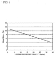
- Figure 1 is a graph showing the relationship between linear recording velocities attainable by phase change materials and absolute difference (Rtop-Rbtm) between Rtop and Rbtm thereof.
- modulation (MOD) of 50 % or more can be derived from formulae (1) and (2). Specifically, modulation (MOD) of 50 % or more can be ensured if the reflectivity (Rtop) of the crystal phase change material satisfies the following formula (3). Rtop ⁇ 22 - (2V/5)
- Rtop is obtained when the reflectivity (Rbtm) of the amorphous phase change material becomes zero, Rtop can be expressed by the following formula (4). Rtop > 11 - (V/5)
- modulation (MOD) of 55 % or more and those required for achieving modulation (MOD) of 60 % or more can be derived from formulae (1) and (2). Specifically, modulation (MOD) of 55 % or more can be ensured if the reflectivity (Rtop) of the crystal phase change material satisfies the following formula (5) and modulation (MOD) of 60 % or more can be ensured if the reflectivity (Rtop) of the crystal phase change material satisfies the following formula (6).
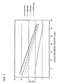
- Figure 2 is a graph corresponding to the above formulae (3) to (6) showing the relationship between linear recording velocities attainable when the modulation (MOD) is 50 %, 55 % or 60 %, and the reflectivity (Rtop) of a crystal phase change material.
- the value to be set as the reflectivity (Rtop) of a crystal phase change material decreases as the attainable linear recording velocity increases.
- a data transfer rate of 70 Mbps taking the format efficiency to be approximately 80% is achieved using the (1,7) RLL modulation code
- the value of Rtop required for achieving modulation (MOD) of 50 % or more is 8.7 % to 14.7 %
- the value of Rtop required for achieving modulation (MOD) of 55% or more is 8.7 % to 15.9 %
- the value of Rtop required for achieving modulation (MOD) of 60 % or more is 8.7 % to 14.5 %.
- Figure 3 is a drawing schematically showing the structure of an optical recording medium 10 that is a preferred embodiment of the present invention.
- an optical recording medium 10 includes a substrate 11, a reflective layer 12 formed on the substrate 11, a second dielectric layer 13 formed on the reflective layer 12, a recording layer 14 formed on the second dielectric layer 13, a barrier layer 15 formed on the recording layer 14, a first dielectric layer 16 formed on the barrier layer 15, a heat radiation layer 17 formed on the first dielectric layer 16 and a light transmission layer 18 formed on the heat radiation layer 17.
- a hole 19 is provided in the center of the optical recording medium 10.
- the substrate 11 serves as a support for ensuring the mechanical strength required by the optical recording medium 10 and it is preferable to set the thickness thereof to be 1.1 mm. While the material for forming the substrate 11 is not particularly limited, polycarbonate can be used to from the substrate 11.
- the reflective layer 12 serves to reflect the laser beam projected onto the recording layer 14 via the light transmission layer 18 and emit it via the light transmission layer 18 and the thickness thereof is preferably set to be 10 to 300 nm.
- the material for forming the reflective layer 12 is not particularly limited but the reflective layer 12 is preferably formed of an alloy containing Ag as a primary component.
- the second dielectric layer 13 mainly serves as a protective layer for the recording layer 14 formed thereon and the thickness thereof is preferably set to be 2 to 50 nm. While the material for forming the second dielectric layer 13 is not particularly limited, Al 2 O 3 , a mixture of ZnS and SiO 2 , CeO 2 , Y 2 O 3 , AlN or the like can be used for forming the second dielectric layer 13.
- the recording layer 14 is formed of a phase change material and data are recorded therein utilizing the difference in reflection coefficient between the case where the recording layer 14 is in the crystal phase and the case where it is in the amorphous phase.
- the reflectivitys in these states are set by adjusting the composition of the phase change material forming the recording layer 14 and, as explained above, they are determined depending upon the target (attainable) linear recording velocity.
- the target (attainable) linear recording velocity is recorded in the optical recording medium 10 as recording condition setting information and when data are to be recorded, the recording condition setting information is read by a drive and data are recorded at a linear recording velocity determined based on the thus read recording condition setting information.
- the recording condition setting information refers to information used for identifying various conditions required for recording data on the optical recording medium 10 concretely including a linear recording velocity, the power of the laser beam, a pulse train pattern described later in detail and the like.
- the recording condition setting information may be recorded in the optical recording medium 10 in the form of wobbles or prepits or may be recorded in the optical recording medium 10 when recording data.
- the recording condition setting information is not limited to specifically designated conditions required to record data but may also include recording conditions designated by specifying one of several conditions stored in advance in the information recording apparatus.
- the power of a laser beam projected from the side of the light transmission layer 18 is modulated in accordance with a pulse waveform having an amplitude extending from a recording power ( Pw ) to a bottom power ( Pb ) so as to heat the recording layer 14 to a temperature higher than the melting point thereof and then quickly cool it by setting the power of the laser beam to the bottom power ( Pb ).
- a pulse waveform having an amplitude extending from a recording power ( Pw ) to a bottom power ( Pb ) so as to heat the recording layer 14 to a temperature higher than the melting point thereof and then quickly cool it by setting the power of the laser beam to the bottom power ( Pb ).
- the recording layer 14 is heated to a temperature equal to or higher than the crystallization temperature thereof by setting the power of the laser beam projected from the side of the light transmission layer 18 to an erasing power ( Pe ).
- the region of the recording layer 14 heated to the temperature equal to or higher than the crystallization temperature thereof is therefore crystallized during the gradual cooling that follows.
- the recording power ( Pw ), the erasing power ( Pe ) and the bottom power ( Pb ) are set so that Pw is higher than Pe and Pe is equal to or higher than Pb . Therefore, if the power of the laser beam is modulated in this manner, it is possible to not only form a recording mark in an unrecorded region of the recording layer 14 but also directly overwrite (direct-overwrite) a recording mark already formed in a region of the recording layer with a different recording mark.
- the material for forming the recording layer 14 is not particularly limited but an SbTe eutectic crystal system material is preferably used for forming the recording layer 14.
- an SbTe eutectic crystal system material InSbTeGeTb is preferable.
- the thickness of the recording layer 14 is preferably set to be 5 to 30 nm.
- the first dielectric layer 16 mainly serves as a protective layer for the recording layer 14 and the thickness thereof is preferably set to be 10 to 300 nm.
- the material for forming the first dielectric layer 16 is not particularly limited but a mixture of ZnS and SiO 2 is preferably used for forming the first dielectric layer 16.
- the barrier layer 15 serves to prevent S (sulfur) contained in the first dielectric layer 16 from reaching the recording layer 14 and the thickness thereof is preferably set to be 2 to 20 nm. While the material for forming the barrier layer 15 is not particularly limited, Al 2 O 3 , SiN, Y 2 O 3 or the like can be used for forming the barrier layer 15. However, in the present invention, it is not absolutely necessary to provide the barrier layer 15 and the barrier layer 15 may be omitted.
- the heat radiation layer 17 serves to effectively radiate heat applied to the recording layer 14 and to enlarge the power margin of the optical recording medium 10. Therefore, it is necessary for the heat radiation layer 17 to have a thermal conductivity higher than at least the first dielectric layer 16 and the heat radiation layer 17 is preferably formed of Al 2 O 3 , AlN or the like. The thickness thereof is preferably set to be 10 to 200 nm and more preferably set to be 30 to 100 nm. However, in the present invention, it is not absolutely necessary to provide the heat radiation layer 17 and the heat radiation layer 17 may be omitted.
- the light transmission layer 18 constitutes the incidence plane of the laser beam and the thickness thereof is preferably set to be 10 to 300 ⁇ m and more preferably set to be 50 to 150 ⁇ m.
- the material for forming the light transmission layer 18 is not particularly limited but an ultraviolet ray curable resin is preferably used for forming the light transmission layer 18.
- Figure 4 is a drawing schematically showing the major components of the drive.
- the drive is equipped with a spindle motor 2 for rotating an optical recording medium 10, an optical head 3 for shining a laser beam onto the optical recording medium 10 and receiving the laser beam reflected from the optical recording medium 10, a controller 4 for controlling the operation of the spindle motor 2 and the optical head 3, a laser driving circuit 5 that supplies a laser driving signal to the optical head 3, and a lens driving circuit 6 that supplies a lens driving signal to the optical head 3.
- the controller 4 includes a focusing servo circuit 7, a tracking servo circuit 8, and a laser control circuit 9.
- the focusing servo circuit 7 When the focusing servo circuit 7 is activated, the focus is aligned with the recording surface of the rotating optical recording medium 10, and when the tracking servo circuit 8 is activated, the spot of the laser beam begins to automatically track the eccentric signal track of the optical recording medium 10.
- the focusing servo circuit 7 and tracking servo circuit 8 are provided with an auto gain control function for automatically adjusting the focusing gain and an auto gain control function for automatically adjusting the tracking gain, respectively.
- the laser control circuit 9 is a circuit that generates the laser driving signal supplied by the laser driving circuit 5 and generates a laser driving signal based on recording condition setting information recorded on the optical recording medium 10.
- the focusing servo circuit 7, tracking servo circuit 8 and laser control circuit 9 need not be circuits incorporated in the controller 4 but can instead be components separate of the controller 4. Moreover, they need not be physical circuits but can instead be accomplished by software programs executed in the controller 4.
- the recording condition setting information recorded on the optical recording medium 10 is read and a linear recording velocity, the power of the laser beam, a pulse train pattern and the like are determined based on the recording condition setting information.
- the pulse train pattern to be used is not particularly limited but considering that the present invention is particularly effective in the case of recording data at a high linear recording velocity, the (1,7)RLL modulation code is preferably used.
- the (1,7)RLL modulation code recording marks of lengths corresponding to 2 T to 8 T are formed in the recording layer 14.
- Figure 5 is a drawing illustrating the pulse train pattern in the case of forming a recording mark of a length corresponding to 2 T .
- the number of pulses in the laser beam is set to 1 .
- the number of pulses in the laser beam is defined by the number of times the power of the laser beam shined during recording is raised to Pw .
- the laser beam power is first set to Pw and then set to the power Pb .
- the laser beam power before the time t s is set to Pe and the power of the laser beam begins to rise at the time t s .
- the laser beam power at the time t e is set to Pe or Pb .
- the recording layer 14 of the optical recording medium 1 receives a large amount of energy and its temperature exceeds the melting point, and during the interval T cl , the recording layer 14 of the optical recording medium 1 is rapidly cooled. Thereby, a recording mark of a length corresponding to 2 T is formed in the recording layer 14 of the optical recording medium 1.
- the power of a laser beam is set to Pw , Pe or Pb and a recording mark of a predetermined length is formed using predetermined pulses.
- optical recording medium 10 having the configuration shown in Figure 3
- the optical recording medium according to the present invention is not limited to the optical recording medium having such a configuration.
- the thickness of the first dielectric layer 16 of the optical recording medium 10-1 was 30 nm
- the thickness of the first dielectric layer 16 of the optical recording medium 10-2 was 40 nm
- the thickness of the first dielectric layer 16 of the optical recording medium 10-3 was 42 nm
- the thickness of the first dielectric layer 16 of the optical recording medium 10-4 was 45 nm.
- the phase change material forming each of the recording layers had a crystallization velocity optimized in the case of recording data at a linear recording velocity of 21.0 m/sec, namely, at a data transfer rate of 140 Mbps taking the format efficiency to be 80%.
- Random signals consisting of recording marks of lengths corresponding to 2 T to 8 T in the (1,7)RLL modulation code were recorded in each of the optical recording media 10-1 to 10-4 under the conditions shown in Table 1.
- the reflectivity (Rtop) of each of the optical recording media 10-1 to 10-4 was measured as follows.
- a plurality of media for measurement including only reflective layers 12 having different thicknesses were fabricated and a laser beam having the same wavelength as that of the laser beam to be used for recording and reproducing data was projected onto a mirror region (a flat region formed with no groove or pit) of each of the media for measurement and the reflectivity thereof was measured using a spectrophotometer, thereby obtaining the relationship between the thickness of the reflective layer 12 and the reflectivity for each of the media for measurement.
- the laser beam which was to be used for recording and reproducing data and whose power was set to a reproducing power was focused onto the mirror region of each of the media for measurement using an evaluation apparatus and a sum signal output voltage value was measured for each of the media for measurement, thereby obtaining the relationship between the thickness of the reflective layer 12 and the sum signal output voltage value for each of the media for measurement.
- the relationship between the reflectivity and the sum signal output voltage value was derived for each of the media for measurement from the thus obtained relationship between the thickness of the reflective layer 12 and the reflectivity and relationship between the thickness of the reflective layer 12 and the sum signal output voltage value for each of the media for measurement.
- the laser beam whose power was set to the reproducing power was tracked along the groove on a region of the recording layer 14 in a crystal phase of each of the optical recording media 10-1 to 10-4 to obtain a sum signal output voltage value and the reflectivity of the region of the recording layer 14 was calculated from the thus obtained sum signal output voltage value and the relationship between the reflectivity and the sum signal output voltage value.
- the result was defined as Rtop.
- Rbtm can be calculated in a similar manner.
- Figure 6 is a graph showing the relationship between the reflectivity (Rtop) of the recording layer 14 in a crystal phase and jitter.
- the reflectivity of the optical recording medium 10-3 satisfied the above mentioned formula (6) and jitter was 10.4 %, i.e., equal to or lower than 10.5 %. To the contrary, it was found that the reflectivity of the optical recording medium 10-4 did not satisfy the above mentioned formula (3) and jitter exceeded the practical upper limit 12 %.
Landscapes
- Optical Record Carriers And Manufacture Thereof (AREA)
- Optical Recording Or Reproduction (AREA)
- Thermal Transfer Or Thermal Recording In General (AREA)
Abstract
It is an object of the present invention to provide an optical recording
medium that is suitable for recording information therein at a high velocity.
An optical recording medium according to the present invention includes a
recording layer formed of a phase change material and capable of recording
data therein at a linear recording velocity equal to or higher than 10 m/sec,
wherein Rtop satisfies the condition that it is larger than {11 - (V/5)} and
smaller than {22 - (2V/5)}, where Rtop (%) is a reflectivity of the crystal
phase change material forming the recording layer and V (m/sec) is a target
linear recording velocity. According to the present invention, since modulation
(MOD) of 50 % or more can be ensured, it is possible to effectively suppress
the degradation of jitter caused by recording data at a high linear recording
velocity equal to or higher than 10 m/sec.
Description
The present invention relates to an optical recording medium and
particularly to an optical recording medium that is suited to record information
therein at a high velocity. In addition, the present invention relates to a method
of recording information to an optical recording medium that can record
information therein at high data transfer rates.
Optical recording media typified by the CD and the DVD and the like
have been widely used as recording media for recording digital data, and a
widely used data recording format is a format wherein the lengths of recording
marks along the track are modulated depending on the data to be recorded. For
example, in a DVD-RW which is one type of optical recording medium whose
data is user-rewritable, recording marks of lengths corresponding to 3T to 11T
(where T is one clock cycle) are used to perform the recording of data.
When a recording mark is formed, a laser beam is shined along the
tracks of the optical recording medium, thereby forming an amorphous region
having a predetermined length in a recording layer included in an optical
recording medium and the thus formed amorphous region is utilized as a
recording mark. Other regions of the recording layer than the amorphous
region are in crystal phase.
When a recording mark is to be formed in a recording layer, a laser
beam whose power is set to a high level (a recording power) is projected onto
the recording layer, thereby heating the recording layer to a temperature higher
than the melting point thereof and the recording layer is then quickly cooled.
As a result, the phase of the recording layer is changed from crystal phase to
amorphous phase and a recording mark is formed in the recording layer. On
the other hand, when a recording mark is to be erased, a laser beam whose
power is set to a relatively low level (an erasing power) is projected onto the
recording layer, thereby heating the recording layer to a temperature equal to
or higher than the crystallization temperature thereof and the recording layer is
then gradually cooled. As a result, the phase of the recording layer is changed
from the amorphous phase to the crystal phase and the recording mark is
erased. Therefore, if the power of the laser beam is modulated in this manner,
it is possible to not only form a recording mark in an unrecorded region of the
recording layer but also directly overwrite (direct-overwrite) a recording mark
already formed in a region of the recording layer with a different recording
mark.
In recent years, it has become highly desirable to achieve further
increases in the data transfer rate with respect to optical recording media and
in order to achieve this, it is effective to form a recording layer of a phase
change material having a high crystallization velocity.
However, in a phase change material having a high crystallization
velocity, the difference between the absolute reflectivity thereof in the crystal
phase and that in the amorphous phase is generally small and when recorded
data are reproduced, good jitter characteristics of the reproduced signal cannot
be obtained. In addition, since the width of a recording mark becomes smaller
as the linear recording velocity is increased in order to increase the data
transfer rate, the degradation of jitter caused by decrease in difference in
absolute reflection coefficient becomes pronounced as the linear recording
velocity increases and the degradation of jitter becomes particularly serious
when the linear recording velocity is equal to or higher than 10 m/sec.
Therefore, although the degradation of jitter caused by decrease in
difference in absolute reflection coefficient is not so serious when the linear
recording velocity is lower than 10 m/sec, the jitter characteristics drastically
deteriorate due to decrease in difference in absolute reflection coefficient
when the linear recording velocity is equal to or higher than 10 m/sec.
Accordingly, it is an object of the present invention to provide an
optical recording medium that is suitable for recording information therein at a
high velocity.
In addition, it is another object of the present invention to provide a
method of recording information to an optical recording medium that can
record information in the optical recording medium at high data transfer rates.
The difference in reflection coefficient between that of a recording
layer formed of a phase change material in the crystal phase and that of the
recording layer formed of the phase change material in the amorphous phase is
generally expressed by a parameter called modulation (MOD) and a greater
output amplitude can be obtained when information is reproduced from a
recording layer having a higher modulation (MOD). Here, the modulation
(MOD) is defined as follows.
MOD = (Rtop - Rbtm)/Rtop
where Rtop is the reflectivity of the phase change material in the crystal phase
and Rbtm is the reflectivity of the phase change material in the amorphous
phase. Here, Rtop and Rbtm are respectively defined as the reflectivity of a
crystalline region and the reflectivity of an amorphous region when tracking of
a condensed laser beam is performed along a groove.
As apparent from the equation (1), the modulation (MOD) can be
increased by increasing the absolute difference between Rtop and Rbtm or
decreasing Rtop. However, as described above, since the absolute difference
between Rtop and Rbtm becomes small as the crystallizing velocity of a phase
change material increases, it is necessary to decrease Rtop in order to increase
the modulation (MOD). This can be achieved by adjusting the thickness of a
dielectric layer(s), for example.
Based on this technical teaching, the inventors of the present invention
found a preferable relationship between a target (attainable) linear recording
velocity and the reflectivity of a recording layer in the crystal phase and
completed the present invention.
Specifically, the above mentioned object of the present invention can
be accomplished by an optical recording medium comprising a recording layer
formed of a phase change material and capable of recording data therein at a
linear recording velocity equal to or higher than 10 m/sec, wherein Rtop
satisfies the condition that it is larger than {11 - (V/5)} and smaller than {22 -
(2V/5)}, where Rtop (%) is a reflectivity of the crystal state of the phase
change material forming the recording layer and V (m/sec) is a target linear
recording velocity.
Further, the above mentioned object of the present invention can be
accomplished by an optical recording medium comprising a recording layer
formed of a phase change material and capable of recording data therein at a
linear recording velocity equal to or higher than 10 m/sec and having
recording condition setting information related to a linear recording velocity V
(m/sec) to be set when recording data, wherein Rtop satisfies the condition
that it is larger than {11 - (V/5)} and smaller than {22 - (2V/5)}, where Rtop
(%) is a reflectivity of the crystal state of the phase change material forming
the recording layer.
According to the present invention, since modulation (MOD) of 50 %
or more can be ensured, it is possible to effectively suppress the degradation of
jitter caused by recording data at a high linear recording velocity equal to or
higher than 10 m/sec.
In a preferred aspect of the present invention, Rtop and V satisfy the
condition that Rtop is larger than {11 - (V/5)} and smaller than {20 -
(4V/11)}.
According to this preferred aspect of the present invention, since
modulation (MOD) of 55 % or more can be ensured, it is possible to more
effectively suppress the degradation of jitter caused by recording data at a high
linear recording velocity equal to or higher than 10 m/sec.
In a further preferred aspect of the present invention, Rtop and V
satisfy a condition that Rtop is larger than {11 - (V/5)} and smaller than {18.3
- (V/3)}.
According to this preferred aspect of the present invention, since
modulation (MOD) of 60 % or more can be ensured, it is possible to more
effectively suppress the degradation of jitter caused by recording data at a high
linear recording velocity equal to or higher than 10 m/sec.
The above object of the present invention can be also accomplished by
a method of recording information to an optical recording medium comprising
a recording layer formed of a phase change material whose reflectivity is Rtop
(%) when it is in a crystal phase, which method records information under the
condition that Rtop is larger than {11 - (V/5)} and smaller than {22 - (2V/5)},
where V (m/sec) is a linear recording velocity.
According to the present invention, since modulation (MOD) of 50 %
or more can be ensured, it is possible to effectively suppress the degradation of
jitter caused by recording data at a high linear recording velocity equal to or
higher than 10 m/sec.
In a preferred aspect of the present invention, information is recorded
under the condition that Rtop is larger than {11- (V/5)} and smaller than {20
- (4V/11)}.
According to this preferred aspect of the present invention, since
modulation (MOD) of 55 % or more can be ensured, it is possible to more
effectively suppress the degradation of jitter caused by recording data at a high
linear recording velocity equal to or higher than 10 m/sec.
In a further preferred aspect of the present invention, information is
recorded under the condition that Rtop is larger than {11- (V/5)} and smaller
than {18.3-(V/3)}.
According to this preferred aspect of the present invention, since
modulation (MOD) of 60 % or more can be ensured, it is possible to more
effectively suppress the degradation of jitter caused by recording data at a high
linear recording velocity equal to or higher than 10 m/sec.
A preferred embodiment of the present invention will be explained in
detail with reference to the drawings.
As pointed out above, it is necessary to increase the crystallizing
velocity of a phase change material forming a recording layer in order to
record data in an optical recording medium at a high data transfer rate and it is
possible to see a substantially constant relationship between linear recording
velocities attainable by phase change materials and absolute difference
between Rtop and Rbtm thereof.
Figure 1 is a graph showing the relationship between linear recording
velocities attainable by phase change materials and absolute difference (Rtop-Rbtm)
between Rtop and Rbtm thereof.
It can be seen from Figure 1 that the absolute difference between Rtop
and Rbtm of a phase change material decreases as the attainable linear
recording velocity of the phase change material increases and that this
tendency is substantially linear. This linear relationship can be expressed by
the following equation (2):
Rtop - Rbtm = 11 - (V/5)
On the other hand, as pointed out above, in order to obtain a
considerably high output amplitude when reproducing data, it is effective to
increase the modulation (MOD) of the recording layer. In particular, since the
width of a recording mark becomes smaller as the linear recording velocity
increases, it is necessary to considerably increase the modulation (MOD) of
the recording layer in the case where the linear recording velocity is equal to
or higher than 10 m/sec. Concretely, in the case where the linear recording
velocity is equal to or higher than 10 m/sec, modulation (MOD) of 50 % or
more is required in order to obtain considerably high output amplitude and the
modulation (MOD) is preferably equal to or higher than 55 %, more
preferably equal to or higher than 60 %.
The conditions required for achieving modulation (MOD) of 50 % or
more can be derived from formulae (1) and (2). Specifically, modulation
(MOD) of 50 % or more can be ensured if the reflectivity (Rtop) of the crystal
phase change material satisfies the following formula (3).
Rtop < 22 - (2V/5)
Further, since it follows from formula (1) that the lower limit of Rtop
is obtained when the reflectivity (Rbtm) of the amorphous phase change
material becomes zero, Rtop can be expressed by the following formula (4).
Rtop > 11 - (V/5)
Moreover, the conditions required for achieving modulation (MOD) of
55 % or more and those required for achieving modulation (MOD) of 60 % or
more can be derived from formulae (1) and (2). Specifically, modulation
(MOD) of 55 % or more can be ensured if the reflectivity (Rtop) of the crystal
phase change material satisfies the following formula (5) and modulation
(MOD) of 60 % or more can be ensured if the reflectivity (Rtop) of the crystal
phase change material satisfies the following formula (6).
Rtop < 20 - (4V/11)
Rtop < 18.3 - (V/3)
Figure 2 is a graph corresponding to the above formulae (3) to (6)
showing the relationship between linear recording velocities attainable when
the modulation (MOD) is 50 %, 55 % or 60 %, and the reflectivity (Rtop) of a
crystal phase change material.
As apparent from Figure 2, the value to be set as the reflectivity (Rtop)
of a crystal phase change material decreases as the attainable linear recording
velocity increases. Concretely, in the case where a data transfer rate of 70
Mbps taking the format efficiency to be approximately 80% is achieved using
the (1,7) RLL modulation code, since the required linear recording velocity is
10.5 m/sec, the value of Rtop required for achieving modulation (MOD) of 50
% or more is 8.7 % to 14.7 %, the value of Rtop required for achieving
modulation (MOD) of 55% or more is 8.7 % to 15.9 % and the value of Rtop
required for achieving modulation (MOD) of 60 % or more is 8.7 % to 14.5
%. Similarly, in the case where a data transfer rate of 140 Mbps taking the
format efficiency to be approximately 80% is achieved using the (1,7) RLL
modulation code, since the required linear recording velocity is 21.0 m/sec,
the value of Rtop required for achieving modulation (MOD) of 50 % or more
is 6.4 % to 12.9 %, the value of Rtop required for achieving modulation
(MOD) of 55 % or more is 6.4 % to 11.7 % and the value of Rtop required for
achieving modulation (MOD) of 60 % or more is 6.4 % to 10.7 %.
Next, the physical structure of an optical recording medium that is a
preferred embodiment of the present invention.
Figure 3 is a drawing schematically showing the structure of an optical
recording medium 10 that is a preferred embodiment of the present invention.
As shown in Figure 3, an optical recording medium 10 includes a
substrate 11, a reflective layer 12 formed on the substrate 11, a second
dielectric layer 13 formed on the reflective layer 12, a recording layer 14
formed on the second dielectric layer 13, a barrier layer 15 formed on the
recording layer 14, a first dielectric layer 16 formed on the barrier layer 15, a
heat radiation layer 17 formed on the first dielectric layer 16 and a light
transmission layer 18 formed on the heat radiation layer 17. A hole 19 is
provided in the center of the optical recording medium 10. When recording
data onto an optical recording medium 10 with such a structure and
reproducing data therefrom, a laser beam is projected from the side of the light
transmission layer 18.
The substrate 11 serves as a support for ensuring the mechanical
strength required by the optical recording medium 10 and it is preferable to set
the thickness thereof to be 1.1 mm. While the material for forming the
substrate 11 is not particularly limited, polycarbonate can be used to from the
substrate 11.
The reflective layer 12 serves to reflect the laser beam projected onto
the recording layer 14 via the light transmission layer 18 and emit it via the
light transmission layer 18 and the thickness thereof is preferably set to be 10
to 300 nm. The material for forming the reflective layer 12 is not particularly
limited but the reflective layer 12 is preferably formed of an alloy containing
Ag as a primary component.
The second dielectric layer 13 mainly serves as a protective layer for
the recording layer 14 formed thereon and the thickness thereof is preferably
set to be 2 to 50 nm. While the material for forming the second dielectric layer
13 is not particularly limited, Al2O3, a mixture of ZnS and SiO2, CeO2, Y2O3,
AlN or the like can be used for forming the second dielectric layer 13.
The recording layer 14 is formed of a phase change material and data
are recorded therein utilizing the difference in reflection coefficient between
the case where the recording layer 14 is in the crystal phase and the case
where it is in the amorphous phase. The reflectivitys in these states are set by
adjusting the composition of the phase change material forming the recording
layer 14 and, as explained above, they are determined depending upon the
target (attainable) linear recording velocity. The target (attainable) linear
recording velocity is recorded in the optical recording medium 10 as recording
condition setting information and when data are to be recorded, the recording
condition setting information is read by a drive and data are recorded at a
linear recording velocity determined based on the thus read recording
condition setting information. Here, the recording condition setting
information refers to information used for identifying various conditions
required for recording data on the optical recording medium 10 concretely
including a linear recording velocity, the power of the laser beam, a pulse train
pattern described later in detail and the like. The recording condition setting
information may be recorded in the optical recording medium 10 in the form
of wobbles or prepits or may be recorded in the optical recording medium 10
when recording data. Further, the recording condition setting information is
not limited to specifically designated conditions required to record data but
may also include recording conditions designated by specifying one of several
conditions stored in advance in the information recording apparatus.
In order to change a region of the recording layer 14 in the crystal
phase to the amorphous phase, the power of a laser beam projected from the
side of the light transmission layer 18 is modulated in accordance with a pulse
waveform having an amplitude extending from a recording power (Pw) to a
bottom power (Pb) so as to heat the recording layer 14 to a temperature higher
than the melting point thereof and then quickly cool it by setting the power of
the laser beam to the bottom power (Pb). As a result, the phase of the region
melted by the laser beam having the recording power (Pw) is changed to the
amorphous phase, thereby forming a recording mark. On the other hand, in
order to crystallize a region of the recording layer 14 in the amorphous phase,
the recording layer 14 is heated to a temperature equal to or higher than the
crystallization temperature thereof by setting the power of the laser beam
projected from the side of the light transmission layer 18 to an erasing power
(Pe). The region of the recording layer 14 heated to the temperature equal to
or higher than the crystallization temperature thereof is therefore crystallized
during the gradual cooling that follows.
Here, the recording power (Pw), the erasing power (Pe) and the
bottom power (Pb) are set so that Pw is higher than Pe and Pe is equal to or
higher than Pb. Therefore, if the power of the laser beam is modulated in this
manner, it is possible to not only form a recording mark in an unrecorded
region of the recording layer 14 but also directly overwrite (direct-overwrite) a
recording mark already formed in a region of the recording layer with a
different recording mark.
The material for forming the recording layer 14 is not particularly
limited but an SbTe eutectic crystal system material is preferably used for
forming the recording layer 14. As the SbTe eutectic crystal system material,
InSbTeGeTb is preferable. The thickness of the recording layer 14 is
preferably set to be 5 to 30 nm.
Similarly to the second dielectric layer 13, the first dielectric layer 16
mainly serves as a protective layer for the recording layer 14 and the thickness
thereof is preferably set to be 10 to 300 nm. The material for forming the first
dielectric layer 16 is not particularly limited but a mixture of ZnS and SiO2 is
preferably used for forming the first dielectric layer 16.
The barrier layer 15 serves to prevent S (sulfur) contained in the first
dielectric layer 16 from reaching the recording layer 14 and the thickness
thereof is preferably set to be 2 to 20 nm. While the material for forming the
barrier layer 15 is not particularly limited, Al2O3, SiN, Y2O3 or the like can be
used for forming the barrier layer 15. However, in the present invention, it is
not absolutely necessary to provide the barrier layer 15 and the barrier layer 15
may be omitted.
The heat radiation layer 17 serves to effectively radiate heat applied to
the recording layer 14 and to enlarge the power margin of the optical
recording medium 10. Therefore, it is necessary for the heat radiation layer 17
to have a thermal conductivity higher than at least the first dielectric layer 16
and the heat radiation layer 17 is preferably formed of Al2O3, AlN or the like.
The thickness thereof is preferably set to be 10 to 200 nm and more preferably
set to be 30 to 100 nm. However, in the present invention, it is not absolutely
necessary to provide the heat radiation layer 17 and the heat radiation layer 17
may be omitted.
The light transmission layer 18 constitutes the incidence plane of the
laser beam and the thickness thereof is preferably set to be 10 to 300 µm and
more preferably set to be 50 to 150 µm. The material for forming the light
transmission layer 18 is not particularly limited but an ultraviolet ray curable
resin is preferably used for forming the light transmission layer 18.
Next, a drive capable of recording data in the optical recording
medium 10 according to this embodiment will be described.
Figure 4 is a drawing schematically showing the major components of
the drive.
As shown in Figure 4, the drive is equipped with a spindle motor 2 for
rotating an optical recording medium 10, an optical head 3 for shining a laser
beam onto the optical recording medium 10 and receiving the laser beam
reflected from the optical recording medium 10, a controller 4 for controlling
the operation of the spindle motor 2 and the optical head 3, a laser driving
circuit 5 that supplies a laser driving signal to the optical head 3, and a lens
driving circuit 6 that supplies a lens driving signal to the optical head 3.
Moreover, as shown in Figure 4, the controller 4 includes a focusing
servo circuit 7, a tracking servo circuit 8, and a laser control circuit 9. When
the focusing servo circuit 7 is activated, the focus is aligned with the recording
surface of the rotating optical recording medium 10, and when the tracking
servo circuit 8 is activated, the spot of the laser beam begins to automatically
track the eccentric signal track of the optical recording medium 10. The
focusing servo circuit 7 and tracking servo circuit 8 are provided with an auto
gain control function for automatically adjusting the focusing gain and an auto
gain control function for automatically adjusting the tracking gain,
respectively. In addition, the laser control circuit 9 is a circuit that generates
the laser driving signal supplied by the laser driving circuit 5 and generates a
laser driving signal based on recording condition setting information recorded
on the optical recording medium 10.
Note that the focusing servo circuit 7, tracking servo circuit 8 and laser
control circuit 9 need not be circuits incorporated in the controller 4 but can
instead be components separate of the controller 4. Moreover, they need not be
physical circuits but can instead be accomplished by software programs
executed in the controller 4.
When data are to recorded in the optical recording medium 10
according to this embodiment using the thus constituted drive, the recording
condition setting information recorded on the optical recording medium 10 is
read and a linear recording velocity, the power of the laser beam, a pulse train
pattern and the like are determined based on the recording condition setting
information. The pulse train pattern to be used is not particularly limited but
considering that the present invention is particularly effective in the case of
recording data at a high linear recording velocity, the (1,7)RLL modulation
code is preferably used. In the (1,7)RLL modulation code, recording marks of
lengths corresponding to 2T to 8 T are formed in the recording layer 14.
Figure 5 is a drawing illustrating the pulse train pattern in the case of
forming a recording mark of a length corresponding to 2T.
As shown in Figure 5, when forming a recording mark of a length
corresponding to 2T, the number of pulses in the laser beam is set to 1. Here,
the number of pulses in the laser beam is defined by the number of times the
power of the laser beam shined during recording is raised to Pw. More
specifically, taking the time ts to be the timing at which the laser beam is
positioned at the starting point of the recording mark and the time te to be the
timing at which the laser beam is positioned at the ending point of the
recording mark, during the period from the time ts to the time te , the laser beam
power is first set to Pw and then set to the power Pb. Here, the laser beam
power before the time ts is set to Pe and the power of the laser beam begins to
rise at the time ts . In addition, the laser beam power at the time te is set to Pe or
Pb.
During the interval Tpulse , the recording layer 14 of the optical
recording medium 1 receives a large amount of energy and its temperature
exceeds the melting point, and during the interval Tcl , the recording layer 14 of
the optical recording medium 1 is rapidly cooled. Thereby, a recording mark
of a length corresponding to 2T is formed in the recording layer 14 of the
optical recording medium 1.
Similarly to the case of forming a recording mark of a length
corresponding to 2T, in the case of forming another recording mark of a length
corresponding to one of 3T to 8T, the power of a laser beam is set to Pw, Pe or
Pb and a recording mark of a predetermined length is formed using
predetermined pulses.
As described above, according to this embodiment, since it is possible
to effectively suppress the degradation of jitter caused by recording data at a
high linear recording velocity, in particular, at a linear recording velocity equal
to or higher than 10 m/sec, data can be recorded at higher data transfer rates.
The present invention is in no way limited to the aforementioned
embodiment, but rather various modifications are possible within the scope of
the invention as recited in the claims, and these are naturally included within
the scope of the invention.
For example, although the foregoing preferred embodiment was
explained with regard to the optical recording medium 10 having the
configuration shown in Figure 3, the optical recording medium according to
the present invention is not limited to the optical recording medium having
such a configuration.
As described above, according to the present invention, since it is
possible to effectively suppress the degradation of jitter caused by recording
data at a high linear recording velocity, in particular, at a linear recording
velocity equal to or higher than 10 m/sec, data can be recorded at higher data
transfer rates.
First, optical recording media 10-1 to 10-4 like that shown in Figure 3
that had a substrate 11 consisting of polycarbonate and having a thickness of
approximately 1.1 mm, a reflective layer 12 consisting of an alloy containing
Ag as a primary component and having a thickness of 100 nm, a second
dielectric layer 13 consisting of a mixture of ZnS and SiO2 (mole ratio of
50:50) and having a thickness of 3 nm, a recording layer 14 containing
InSbTeGeTb and having a thickness of 14 nm, a barrier layer 15 consisting of
Al2O3 and having a thickness of 5 nm, a first dielectric layer 16 consisting of a
mixture of ZnS and SiO2 (mole ratio of 80:20), a heat radiation layer 17
consisting of AlN and having a thickness of 100 nm, and a light transmission
layer 18 consisting of an ultraviolet ray curable resin and having a thickness of
100 µm were prepared. These optical recording media were different from
each other only in the thickness of the first dielectric layer 16 and, as a result,
the reflectivitys (Rtop) of their recording layers in a crystal phase were
different from each other. The thickness of the first dielectric layer 16 of the
optical recording medium 10-1 was 30 nm, the thickness of the first dielectric
layer 16 of the optical recording medium 10-2 was 40 nm, the thickness of the
first dielectric layer 16 of the optical recording medium 10-3 was 42 nm and
the thickness of the first dielectric layer 16 of the optical recording medium
10-4 was 45 nm. The phase change material forming each of the recording
layers had a crystallization velocity optimized in the case of recording data at
a linear recording velocity of 21.0 m/sec, namely, at a data transfer rate of 140
Mbps taking the format efficiency to be 80%.
Random signals consisting of recording marks of lengths
corresponding to 2T to 8T in the (1,7)RLL modulation code were recorded in
each of the optical recording media 10-1 to 10-4 under the conditions shown
in Table 1.
| Clock frequency | 262.5 MHz |
| Clock period (1T) | 3.8 nsec |
| Linear recording velocity (CLV) | 21.0 m/sec |
| Modulation code | (1,7)RLL |
| Data transfer rate | 175 Mbps |
| Format efficiency | 80 % |
| Data transfer rate (taking efficiency into account) | 140 Mbps |
| Channel bit length | 0.12 µm/bit |
| Numerical aperture | 0.85 |
| Laser wavelength | 405 nm |
| Pw | 7.0 to 8.0 mW |
| Pe | 2.2 mW |
| Pb | 0.1 mW |
Then, clock jitter of the random signals recorded in each of the optical
recording media 10-1 to 10-4 was measured. When clock jitter was measured,
the fluctuation σ of a reproduced signal was measured using a time interval
analyzer and the clock jitter was calculated as σ/Tw, where Tw was one clock
period. The results of the measurement are shown in Table 2. In Table 2, the
reflectivity (Rtop) of the recording layer 14 in a crystal phase is shown for
each of the optical recording media 10-1 to 10-4.
| Jitter | Rtop | |
| Optical Recording Medium 10-1 | 11.8 % | 12.5 % |
| Optical Recording Medium 10-2 | 10.9 % | 11.0 % |
| Optical Recording Medium 10-3 | 10.4 % | 7.3 % |
| Optical Recording Medium 10-4 | 12.7 % | 17.0 % |
Here, the reflectivity (Rtop) of each of the optical recording media 10-1
to 10-4 was measured as follows.
First, a plurality of media for measurement including only reflective
layers 12 having different thicknesses were fabricated and a laser beam having
the same wavelength as that of the laser beam to be used for recording and
reproducing data was projected onto a mirror region (a flat region formed with
no groove or pit) of each of the media for measurement and the reflectivity
thereof was measured using a spectrophotometer, thereby obtaining the
relationship between the thickness of the reflective layer 12 and the
reflectivity for each of the media for measurement. Further, the laser beam
which was to be used for recording and reproducing data and whose power
was set to a reproducing power was focused onto the mirror region of each of
the media for measurement using an evaluation apparatus and a sum signal
output voltage value was measured for each of the media for measurement,
thereby obtaining the relationship between the thickness of the reflective layer
12 and the sum signal output voltage value for each of the media for
measurement.
Then, the relationship between the reflectivity and the sum signal
output voltage value was derived for each of the media for measurement from
the thus obtained relationship between the thickness of the reflective layer 12
and the reflectivity and relationship between the thickness of the reflective
layer 12 and the sum signal output voltage value for each of the media for
measurement.
Further, the laser beam whose power was set to the reproducing power
was tracked along the groove on a region of the recording layer 14 in a crystal
phase of each of the optical recording media 10-1 to 10-4 to obtain a sum
signal output voltage value and the reflectivity of the region of the recording
layer 14 was calculated from the thus obtained sum signal output voltage
value and the relationship between the reflectivity and the sum signal output
voltage value. The result was defined as Rtop. Rbtm can be calculated in a
similar manner.
As shown in Table 2, jitter of the random signals became better as the
reflectivity (Rtop) of the recording layer 14 in a crystal phase of the optical
recording medium was lower. Then, a graph showing the relationship between
the reflectivity (Rtop) of the recording layer 14 in a crystal phase and jitter
was made using the values shown in Table 2.
Figure 6 is a graph showing the relationship between the reflectivity
(Rtop) of the recording layer 14 in a crystal phase and jitter.
As shown in Figure 6, it was found that there was a constant
relationship between the reflectivity (Rtop) of the recording layer 14 in a
crystal phase and jitter and jitter decreased as the reflectivity (Rtop) of the
recording layer 14 in a crystal phase was lower. Here, it was found that the
reflectivity of the optical recording medium 10-1 satisfied the above
mentioned formula (3) and jitter was 11.8 %, i.e., equal to or lower than the
practical upper limit 12 %, and it was found that the reflectivity of the optical
recording medium 10-2 satisfied the above mentioned formula (5) and jitter
was 10.9 %, i.e., equal to or lower than 11 %. Further, it was found that the
reflectivity of the optical recording medium 10-3 satisfied the above
mentioned formula (6) and jitter was 10.4 %, i.e., equal to or lower than 10.5
%. To the contrary, it was found that the reflectivity of the optical recording
medium 10-4 did not satisfy the above mentioned formula (3) and jitter
exceeded the practical upper limit 12 %.
Claims (9)
- An optical recording medium comprising a recording layer formed of a phase change material and capable of recording data therein at a linear recording velocity equal to or higher than 10 m/sec, wherein Rtop satisfies the condition that it is larger than {11 - (V/5)} and smaller than {22 - (2V/5)}, where Rtop (%) is a reflectivity of the crystal state of the phase change material forming the recording layer and V (m/sec) is a target linear recording velocity.
- An optical recording medium in accordance with Claim 1, wherein Rtop and V satisfy the condition that Rtop is larger than {11 - (V/5)} and smaller than {20- (4V/11)}.
- An optical recording medium in accordance with Claim 1, wherein Rtop and V satisfy the condition that Rtop is larger than {11 - (V/5)} and smaller than {18.3 - (V/3)}.
- An optical recording medium comprising a recording layer formed of a phase change material and capable of recording data therein at a linear recording velocity equal to or higher than 10 m/sec and having recording condition setting information related to a linear recording velocity V (m/sec) that should be set when recording data, wherein Rtop satisfies the condition that it is larger than {11 - (V/5)} and smaller than {22 - (2V/5)}, where Rtop (%) is a reflectivity of the crystal state of the phase change material forming the recording layer.
- An optical recording medium in accordance with Claim 4, wherein Rtop and V satisfy the condition that Rtop is larger than {11 - (V/5)} and smaller than {20 - (4V/11)}.
- An optical recording medium in accordance with Claim 4, wherein Rtop and V satisfy the condition that Rtop is larger than {11 - (V/5)} and smaller than {18.3-(V/3)}.
- A method of recording information to an optical recording medium comprising a recording layer formed of a phase change material whose reflectivity is Rtop (%) when it is in a crystal phase, which method records information under the condition that Rtop is larger than {11 - (V/5)} and smaller than {22 - (2V/5)}, where V (m/sec) is a linear recording velocity.
- A method of recording information to an optical recording medium in accordance with Claim 7, wherein information is recorded under the condition that Rtop is larger than {11 - (V/5)} and smaller than {20 - (4V/11)}.
- A method of recording information to an optical recording medium in accordance with Claim 7, wherein information is recorded under the condition that Rtop is larger than {11 - (V/5)} and smaller than {18.3 - (V/3)}.
Applications Claiming Priority (3)
| Application Number | Priority Date | Filing Date | Title |
|---|---|---|---|
| JP2002032026A JP2003233929A (en) | 2002-02-08 | 2002-02-08 | Optical recording medium and method of recording information on optical recording medium |
| JP2002032026 | 2002-02-08 | ||
| PCT/JP2003/000861 WO2003067580A1 (en) | 2002-02-08 | 2003-01-29 | Optical recording medium and method for recording information on optical recording medium |
Publications (2)
| Publication Number | Publication Date |
|---|---|
| EP1473712A1 true EP1473712A1 (en) | 2004-11-03 |
| EP1473712A4 EP1473712A4 (en) | 2008-04-30 |
Family
ID=27677952
Family Applications (1)
| Application Number | Title | Priority Date | Filing Date |
|---|---|---|---|
| EP03703079A Withdrawn EP1473712A4 (en) | 2002-02-08 | 2003-01-29 | Optical recording medium and method for recording information on optical recording medium |
Country Status (5)
| Country | Link |
|---|---|
| US (1) | US7227832B2 (en) |
| EP (1) | EP1473712A4 (en) |
| JP (1) | JP2003233929A (en) |
| AU (1) | AU2003208059A1 (en) |
| WO (1) | WO2003067580A1 (en) |
Families Citing this family (6)
| Publication number | Priority date | Publication date | Assignee | Title |
|---|---|---|---|---|
| US7177262B2 (en) * | 2002-04-19 | 2007-02-13 | Victor Company Of Japan, Ltd. | Reproducing system and corresponding information recording medium having wobbled land portions |
| JP2004220699A (en) * | 2003-01-15 | 2004-08-05 | Tdk Corp | Optical recording medium |
| JP4078237B2 (en) * | 2003-03-28 | 2008-04-23 | Tdk株式会社 | Optical recording medium, optical recording method, and optical recording apparatus |
| JP4354733B2 (en) * | 2003-04-18 | 2009-10-28 | Tdk株式会社 | Optical recording medium |
| JP4167146B2 (en) * | 2003-08-19 | 2008-10-15 | Tdk株式会社 | Optical recording medium and method for manufacturing the same, and data recording method and data reproducing method for optical recording medium |
| JP2008159137A (en) * | 2006-12-22 | 2008-07-10 | Tdk Corp | Optical recording and reproducing method, optical recording and reproducing device, optical recording medium |
Family Cites Families (13)
| Publication number | Priority date | Publication date | Assignee | Title |
|---|---|---|---|---|
| US6020041A (en) * | 1997-12-15 | 2000-02-01 | Eastman Kodak Company | Performance recording media for recordable element using gold reflector |
| JP2000298879A (en) * | 1999-04-13 | 2000-10-24 | Sony Corp | Optical recording medium |
| DE60042907D1 (en) * | 1999-05-19 | 2009-10-15 | Mitsubishi Kagaku Media Co Ltd | Record at constant angular velocity |
| EP1152402B1 (en) * | 1999-07-15 | 2006-11-15 | Matsushita Electric Industrial Co., Ltd. | Optical recording medium and method for recording optical recording medium |
| JP2002157737A (en) * | 2000-05-12 | 2002-05-31 | Tdk Corp | Optical recording method and optical recording medium |
| JP4255202B2 (en) * | 2000-06-20 | 2009-04-15 | Tdk株式会社 | Optical recording method |
| JP2002008269A (en) * | 2000-06-22 | 2002-01-11 | Sony Corp | Optical recording medium and manufacturing method thereof |
| JP2002079757A (en) * | 2000-06-23 | 2002-03-19 | Tdk Corp | Optical recording medium |
| JP2002015463A (en) * | 2000-06-26 | 2002-01-18 | Nec Corp | optical disk |
| CN1194348C (en) * | 2000-11-30 | 2005-03-23 | 日本胜利株式会社 | Optical recording medium |
| US6497988B2 (en) * | 2001-02-22 | 2002-12-24 | Eastman Kodak Company | Phase-change recording element for write once applications |
| TWI226058B (en) * | 2002-09-11 | 2005-01-01 | Tdk Corp | Optical recording medium |
| JP2004322468A (en) * | 2003-04-24 | 2004-11-18 | Tdk Corp | Optical recording medium |
-
2002
- 2002-02-08 JP JP2002032026A patent/JP2003233929A/en active Pending
-
2003
- 2003-01-29 EP EP03703079A patent/EP1473712A4/en not_active Withdrawn
- 2003-01-29 AU AU2003208059A patent/AU2003208059A1/en not_active Abandoned
- 2003-01-29 US US10/502,000 patent/US7227832B2/en not_active Expired - Lifetime
- 2003-01-29 WO PCT/JP2003/000861 patent/WO2003067580A1/en not_active Ceased
Also Published As
| Publication number | Publication date |
|---|---|
| EP1473712A4 (en) | 2008-04-30 |
| US7227832B2 (en) | 2007-06-05 |
| WO2003067580A1 (en) | 2003-08-14 |
| AU2003208059A1 (en) | 2003-09-02 |
| JP2003233929A (en) | 2003-08-22 |
| US20050041568A1 (en) | 2005-02-24 |
Similar Documents
| Publication | Publication Date | Title |
|---|---|---|
| US7336580B2 (en) | Optical recording method, optical recorder, and optical recording medium | |
| US20080310270A1 (en) | Information recording method and apparatus with suppressed mark edge jitters | |
| EP1484752B1 (en) | Method for recording information on optical recording medium and information recorder | |
| US7408860B2 (en) | Method of recording information in optical recording medium, information recording apparatus and optical recording medium | |
| EP1752973B1 (en) | Method of recording information in optical recording medium, information recording apparatus and optical recording medium | |
| US20070153671A1 (en) | Optical recording medium and recording system for the same | |
| US7227832B2 (en) | Optical recording medium and method of recording information to optical recording medium | |
| US8034530B2 (en) | Method of recording information in optical recording medium, information recording, apparatus and optical recording medium | |
| US7082090B2 (en) | Method of recording information to an optical recording medium, information recording apparatus, and optical recording medium | |
| US7471606B2 (en) | Method of recording information on optical recording medium, and information recording and reproducing apparatus | |
| EP1467353A1 (en) | Method for recording information on optical recording medium, optical recording medium, and information recorder/reproducer | |
| US7149154B2 (en) | Medium and method for providing a desirable direct overwriting characteristic for optical data recorded at different linear recording velocities | |
| EP1475786A1 (en) | Method for recording information on optical recording medium, information recorder, and optical recording medium | |
| US7742374B2 (en) | Method of recording data on optical recording media and optical recording device | |
| US7738335B2 (en) | Method and apparatus for recording information on an optical recording medium | |
| EP1434203A1 (en) | OPTICAL RECORDING MEDIUM&comma; METHOD AND APPARATUS FOR RECORDING INFORMATION ON OPTICAL RECORDING MEDIUM | |
| JP2005332579A (en) | Information recording method on optical recording medium, information recorder and optical recording medium | |
| JP2003099930A (en) | Method of recording information on optical recording medium, information recording device, and optical recording medium | |
| JP2005302297A (en) | Method for recording information to optical recording medium, information recording device and optical recording medium | |
| JP2003191637A (en) | Optical recording medium and information recording method thereto | |
| JP2003099936A (en) | Information recording method to optical recording medium, information recording device, optical recording medium and evaluation method for optical recording medium |
Legal Events
| Date | Code | Title | Description |
|---|---|---|---|
| PUAI | Public reference made under article 153(3) epc to a published international application that has entered the european phase |
Free format text: ORIGINAL CODE: 0009012 |
|
| 17P | Request for examination filed |
Effective date: 20040721 |
|
| AK | Designated contracting states |
Kind code of ref document: A1 Designated state(s): AT BE BG CH CY CZ DE DK EE ES FI FR GB GR HU IE IT LI LU MC NL PT SE SI SK TR |
|
| A4 | Supplementary search report drawn up and despatched |
Effective date: 20080402 |
|
| STAA | Information on the status of an ep patent application or granted ep patent |
Free format text: STATUS: THE APPLICATION HAS BEEN WITHDRAWN |
|
| 18W | Application withdrawn |
Effective date: 20080620 |