EP1473495A1 - Float for automatic bleeder valve and valve with said float - Google Patents
Float for automatic bleeder valve and valve with said float Download PDFInfo
- Publication number
- EP1473495A1 EP1473495A1 EP04076217A EP04076217A EP1473495A1 EP 1473495 A1 EP1473495 A1 EP 1473495A1 EP 04076217 A EP04076217 A EP 04076217A EP 04076217 A EP04076217 A EP 04076217A EP 1473495 A1 EP1473495 A1 EP 1473495A1
- Authority
- EP
- European Patent Office
- Prior art keywords
- float
- valve according
- valve
- bridge
- cap
- Prior art date
- Legal status (The legal status is an assumption and is not a legal conclusion. Google has not performed a legal analysis and makes no representation as to the accuracy of the status listed.)
- Granted
Links
Images


Classifications
-
- F—MECHANICAL ENGINEERING; LIGHTING; HEATING; WEAPONS; BLASTING
- F16—ENGINEERING ELEMENTS AND UNITS; GENERAL MEASURES FOR PRODUCING AND MAINTAINING EFFECTIVE FUNCTIONING OF MACHINES OR INSTALLATIONS; THERMAL INSULATION IN GENERAL
- F16K—VALVES; TAPS; COCKS; ACTUATING-FLOATS; DEVICES FOR VENTING OR AERATING
- F16K24/00—Devices, e.g. valves, for venting or aerating enclosures
- F16K24/04—Devices, e.g. valves, for venting or aerating enclosures for venting only
- F16K24/042—Devices, e.g. valves, for venting or aerating enclosures for venting only actuated by a float
- F16K24/048—Devices, e.g. valves, for venting or aerating enclosures for venting only actuated by a float a transmission element, e.g. arm, being interposed between the float and the valve element, the transmission element following a non-translational, e.g. pivoting or rocking, movement when actuated
Definitions
- the present invention relates to a float for automatic bleeder valves and an associated automatic valve with float, for bleeding fluid recirculating systems.
- valves in addition to being connected directly to the system, must be able to be housed, for example, in special seats provided in the recirculation pumps, constructional forms have been developed without the bowl, the function of which is instead performed directly by said valve seats.
- valves for example disclosed in IT 0,237,091, have been developed, said valves being equipped with an element for protecting the float in the form of a basket with a bottom transverse part for connecting the side walls of the said basket.
- this basket Although performing its function, this basket has, however, the drawback that it consists of a separate part to be associated with the cap during assembly, with a consequent increase in the associated production and storage costs; in addition to this, the basket in turn constitutes a delicate part exposed to knocks and breakages.
- the technical problem which is posed, therefore, is that of designing a float for bleeder valves and a bleeder valve with float for fluid recirculating systems, in particular hydraulic systems, provided with means for supporting the float which are not exposed to knocks and/or breakages and which may at the same time form means for guiding the float so as to prevent misalignment of the latter with consequent malfunctioning of the valve.
- a float for an automatic valve for bleeding the air in fluid recirculating systems comprising a cap and having air bleeding means, which comprises a body able to be engaged in a longitudinal direction with said cap, the front surface of said body being provided with at least a first element and a second element able to interfere in an axial direction with said bleeding means.
- the present invention also relates to an air bleeder valve for fluid recirculating systems, in particular thermo/hydro/sanitary hydraulic systems, comprising a float as described above.
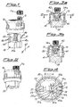
- the valve according to the present invention essentially consists of a cap 10 shaped so as to have: a duct 11, substantially parallel to the vertical axis and able to be shut off by a screw-type closing stopper 11a, and a duct 12 which is substantially horizontal (Fig. 4), passing through both the cap 10 and a step 14 with an internal front surface 14a, formed inside the cap 10 and able to allow insertion of the bleeder valve 20.
- the sides of the step 14 parallel to the transverse direction X-X are provided with bearing surfaces 14b arranged on opposite sides of the opening of the duct 12.
- the cap 10 is also provided internally with longitudinal guides 13 arranged parallel to the said front surface 14a and at a suitable distance therefrom in the transverse direction so as to form a cavity 15, the purpose of which will become obvious below.
- Said valve 20 is of the conventional type which can be opened/closed by mean of a lever 21, a first end of which is joined to the sealing element 23 axially retained by a spring 23a and the other end of which is connected to a float 30 which is free to travel in both senses longitudinally between the two - top and bottom - end-of-travel positions which are respectively defined by the upper floating limit on the water (the float strikes the inside of the cap 10) and by guiding and retaining means described below.
- the float 30 has two bridge elements 40 and 50 which are arranged in a position substantially aligned in the transverse direction X-x and extending, in the preferred example illustrated, with different heights in the longitudinal direction Y-Y.
- the first bridge element 40 has uprights 41 with a cross-section substantially in the form of a "T", the head 41a of which is able to be arranged with its internal surfaces bearing against the corresponding surfaces of the uprights 13 and the surfaces 14b of the step 14 in the cap 10; the shank 41b of the "T” is instead able to be inserted inside the cavity 15 present between the longitudinal guides 13 and the internal front surface 14a of the step 14.
- the transverse element 42 of the bridge element 40 has a width corresponding to that of the shank of the "T" so as to be able to pass into said cavity 15 of the cap 10 and facilitate movement of the float without sticking.
- the second bridge element 50 has uprights 51 and a cross-piece 52 which are substantially smooth.
- the cap 10 has an annular edge 17 which projects outwards and the top surface 17a and bottom surface 17b of which are respectively able to form the bearing surface of means 70a for constraining the valve to the associated seat 80 which is only schematically shown in the figures and of a sealing element 70b for example an O-ring.
- These constraining means 70a are preferably of the rapid-engagement type and consist of a resilient U-shaped fork which can be inserted into special locating recesses 81 formed in the said seat 80 for the valve.
- the system for engagement between cap and seat may of the screw/female thread type.
- the bridge element 40 may have uprights 41 with a different cross-section, for example a rectangular or circular cross-section.
- Figs. 7a and 7b show a variation of embodiment of a valve with float according to the present invention; in this configuration bleeding 111,111a of the valve is performed in a direction parallel to that of the duct 12 for inserting the valve 120.
- the elements interfering with the valve 120 may consist of a hollow polygonal element 140, 150 supported by a single upright 141,151.
- Said polygonal element may be closed, as shown, or open, for example in form of a hook.
- the said retaining action is therefore provided solely by elements integral with the float in conjunction with functional means of the valve, without the need for further additional parts designed for this purpose.
- the float is prevented from rotating about itself and/or from being inclined, thereby eliminating the drawbacks resulting from sticking and consequent malfunctioning of the bleeder.
- FIGS 8,9a,9b show a further embodiment of the valve according to the present invention which envisages also means 200 for manually bleeding the air which are useful when filling the system or in the event of malfunctioning of the automatic device controlled by the float 30.
- Said means 200 comprise an obturator 210 which is formed by a shank 211 and by a base 212; the shank 211 is housed inside a corresponding open seat 220 able to connect the interior of the cap 10 with the external environment, while the base 212 has a surface such as to bear against the inside edge of said seat 220 in order to produce closing thereof, as will emerge more clearly below.
- a spring 213 is arranged coaxially with the shank 211, said spring being able to exert a thrusting action between a bearing surface of the seat 220 and a head-piece 214 joined to the shank 211 on the opposite side to the base 212.
- a sealing element 215 of the O-ring type is arranged between the base 212 of the obturator 200 and inside edge of the seat 210.
Landscapes
- Engineering & Computer Science (AREA)
- General Engineering & Computer Science (AREA)
- Mechanical Engineering (AREA)
- Self-Closing Valves And Venting Or Aerating Valves (AREA)
- Float Valves (AREA)
- Respiratory Apparatuses And Protective Means (AREA)
Abstract
Description
- The present invention relates to a float for automatic bleeder valves and an associated automatic valve with float, for bleeding fluid recirculating systems.
- It is known in the technical sector of fluid recirculating systems, such as hydraulic systems, in particular hydro/thermo/sanitary systems, that there exists the need to provide automatic valves for bleeding the air which accumulates inside the said system; said valves are generally mounted at the highest points or at suitable points within the system. For this purpose automatic bleeder valves have been designed, essentially comprising an upper cap having, associated therewith, a bleeder valve which is opened/closed by a lever connected to a float which moves up and down with the free surface of the fluid present inside a bowl coaxially joined in a sealed manner to the cap and connected to the system, the level of the said free surface of the fluid being in turn determined by the presence of a greater or smaller quantity of air in the system.
- Since it is required, however, that said valves, in addition to being connected directly to the system, must be able to be housed, for example, in special seats provided in the recirculation pumps, constructional forms have been developed without the bowl, the function of which is instead performed directly by said valve seats.
- The elimination of the bowl, however, poses a further problem consisting in the fact that the float is no longer housed inside a container and may come loose and/or be damaged during handling and/or transportation, resulting in the entire valve being unusable.
- In order to solve this problem, valves, for example disclosed in IT 0,237,091, have been developed, said valves being equipped with an element for protecting the float in the form of a basket with a bottom transverse part for connecting the side walls of the said basket.
- Although performing its function, this basket has, however, the drawback that it consists of a separate part to be associated with the cap during assembly, with a consequent increase in the associated production and storage costs; in addition to this, the basket in turn constitutes a delicate part exposed to knocks and breakages.
- The technical problem which is posed, therefore, is that of designing a float for bleeder valves and a bleeder valve with float for fluid recirculating systems, in particular hydraulic systems, provided with means for supporting the float which are not exposed to knocks and/or breakages and which may at the same time form means for guiding the float so as to prevent misalignment of the latter with consequent malfunctioning of the valve.
- In connection with this problem a further requirement is that these means should have small dimensions and be easy and inexpensive to manufacture.
- These results are obtained according to the present invention by a float for an automatic valve for bleeding the air in fluid recirculating systems comprising a cap and having air bleeding means, which comprises a body able to be engaged in a longitudinal direction with said cap, the front surface of said body being provided with at least a first element and a second element able to interfere in an axial direction with said bleeding means.
- The present invention also relates to an air bleeder valve for fluid recirculating systems, in particular thermo/hydro/sanitary hydraulic systems, comprising a float as described above.
- Further details may be obtained from the following description of a non-limiting example of embodiment of the present invention, provided with reference to the accompanying drawings in which:
- Figure 1 shows an exploded view of a valve according to the present invention;
- Figure 2 shows a perspective view of a valve according to the present invention;
- Figure 3a shows a cross-section along a vertical plane of the valve shown in Fig. 2, with the float in the lowered position;
- Figure 3b shows a schematic cross-section similar to that of Fig. 3a, with the float in the raised position;
- Figure 4 shows a cross-section along the plane indicated by IV-IV in Fig. 3;
- Figure 5 shows a schematic cross-section along a vertical plane of the valve inserted in its seat and in the sealed condition;
- Figure 6a shows a partial cross-section similar to that of Fig. 5 with the valve in the bleeding condition;
- Figure 6b shows a further schematic cross-section through the valve according to Fig. 5;
- Figure 7a shows a perspective view of a second embodiment of the valve according to the present invention;
- Figure 7b shows a schematic cross-section along a vertical plane of the valve according to Fig. 7a;
- Figure 8 shows a top plan view of a further example of embodiment of a valve according to the present invention with manual bleeding means;
- Figure 9a shows a cross-section along the plane indicated by IX-IX in Fig. 8 with manual bleeding in the rest condition; and
- Figure 9b shows a cross-section along the plane indicated by IX-IX in Fig. 8 with manual bleeding activated.
- As illustrated and referring to a Cartesian reference system formed by a transverse/horizontal axis X-X and a longitudinal/vertical axis Y-Y, assumed conventionally for the sake of convenience of the description, the valve according to the present invention essentially consists of a
cap 10 shaped so as to have: aduct 11, substantially parallel to the vertical axis and able to be shut off by a screw-type closing stopper 11a, and aduct 12 which is substantially horizontal (Fig. 4), passing through both thecap 10 and astep 14 with aninternal front surface 14a, formed inside thecap 10 and able to allow insertion of thebleeder valve 20. - The sides of the
step 14 parallel to the transverse direction X-X are provided with bearingsurfaces 14b arranged on opposite sides of the opening of theduct 12. - The
cap 10 is also provided internally withlongitudinal guides 13 arranged parallel to the saidfront surface 14a and at a suitable distance therefrom in the transverse direction so as to form acavity 15, the purpose of which will become obvious below. - Said
valve 20 is of the conventional type which can be opened/closed by mean of alever 21, a first end of which is joined to the sealingelement 23 axially retained by aspring 23a and the other end of which is connected to afloat 30 which is free to travel in both senses longitudinally between the two - top and bottom - end-of-travel positions which are respectively defined by the upper floating limit on the water (the float strikes the inside of the cap 10) and by guiding and retaining means described below. - In greater detail the
float 30 has twobridge elements 40 and 50 which are arranged in a position substantially aligned in the transverse direction X-x and extending, in the preferred example illustrated, with different heights in the longitudinal direction Y-Y. - The
first bridge element 40 hasuprights 41 with a cross-section substantially in the form of a "T", thehead 41a of which is able to be arranged with its internal surfaces bearing against the corresponding surfaces of theuprights 13 and thesurfaces 14b of thestep 14 in thecap 10; theshank 41b of the "T" is instead able to be inserted inside thecavity 15 present between thelongitudinal guides 13 and theinternal front surface 14a of thestep 14. - In the preferred embodiment illustrated, the
transverse element 42 of thebridge element 40 has a width corresponding to that of the shank of the "T" so as to be able to pass into saidcavity 15 of thecap 10 and facilitate movement of the float without sticking. - The second bridge element 50 has
uprights 51 and across-piece 52 which are substantially smooth. - Assembly of the valve is performed as follows:
- the
cap 10 is prepared; - the
float 30 is inserted axially inside it with thebridge elements 40 and 50 directed towards the inside of the cap and with - the
head part 41a of the T-shaped uprights 41 inserted in contact with the respective surfaces of theuprights 13 and thesurface 14b of thestep 14; - once the end-of-travel position has been reached in
the axial direction, the
float 30 has the opening of thebridge elements 40 and 50 aligned with the opening of theduct 12; - insertion of the
valve 20 in the transverse direction produces insertion of a valve part underneath thebridge element 40 and the end of thelever 21 underneath the bridge element 50. - In a preferred embodiment it is envisaged moreover that the
cap 10 has anannular edge 17 which projects outwards and the top surface 17a and bottom surface 17b of which are respectively able to form the bearing surface ofmeans 70a for constraining the valve to the associatedseat 80 which is only schematically shown in the figures and of asealing element 70b for example an O-ring. - These constraining means 70a are preferably of the rapid-engagement type and consist of a resilient U-shaped fork which can be inserted into special locating recesses 81 formed in the said
seat 80 for the valve. - Alternatively it is envisaged that the system for engagement between cap and seat may of the screw/female thread type. During operation of the valve illustrated in Figs. 5,6a and 6b:
- in normal operating conditions (Fig. 5) the
float 30 is raised, being pushed by the water; - as a result the
lever 21 is recalled by thespring 23a into the position for closing the bleeder; - if the quantity of air in the fluid increases, the float tends to move downwards (Fig. 6a) in the axial direction; and
- the second bridge element 50 bears (Fig. 6a) against
the end of the
lever 21, causing rotation thereof in the anti-clockwise direction resulting in opening of the bleeder; - during its travel in the axial direction the float is
guided by the
longitudinal guides 13, by thesurfaces step 14 and by theuprights 41 of thefirst bridge element 40; - the float is nevertheless prevented from becoming
detached from the
cap 10 by the interfering action of thecross-piece 42 of thefirst bridge element 40 with thevalve 20 which prevents it from coming out completely in the axial direction, making contact with the said cross-piece. - It is envisaged moreover that the
bridge element 40 may haveuprights 41 with a different cross-section, for example a rectangular or circular cross-section. - Figs. 7a and 7b show a variation of embodiment of a valve with float according to the present invention; in this configuration bleeding 111,111a of the valve is performed in a direction parallel to that of the
duct 12 for inserting thevalve 120. - In addition to this it is envisaged that the elements interfering with the
valve 120 may consist of a hollowpolygonal element - Said polygonal element may be closed, as shown, or open, for example in form of a hook.
- The said retaining action is therefore provided solely by elements integral with the float in conjunction with functional means of the valve, without the need for further additional parts designed for this purpose.
- In addition to this, the float is prevented from rotating about itself and/or from being inclined, thereby eliminating the drawbacks resulting from sticking and consequent malfunctioning of the bleeder.
- Figures 8,9a,9b show a further embodiment of the valve according to the present invention which envisages also means 200 for manually bleeding the air which are useful when filling the system or in the event of malfunctioning of the automatic device controlled by the
float 30. - Said means 200 comprise an obturator 210 which is formed by a
shank 211 and by abase 212; theshank 211 is housed inside a correspondingopen seat 220 able to connect the interior of thecap 10 with the external environment, while thebase 212 has a surface such as to bear against the inside edge of saidseat 220 in order to produce closing thereof, as will emerge more clearly below. - A
spring 213 is arranged coaxially with theshank 211, said spring being able to exert a thrusting action between a bearing surface of theseat 220 and a head-piece 214 joined to theshank 211 on the opposite side to thebase 212. - In this way:
- in the rest condition (Fig. 9a) the
spring 213 pushes the obturator 210 outwards so that the base 212 bears against the inside edge of theseat 220 so as to close it; - if required (Fig. 9b) it is possible to exert an
axial thrust against the head-
piece 214 so as to overcome the reaction of thespring 213 and cause displacement of the obturator towards the inside of the cap in order to obtain opening of theseat 220 and a downwards thrust on thelever 21 able to activate bleeding of the air which occurs along thenormal path 11 and/or the seat 210 itself. - In a preferred embodiment a sealing
element 215 of the O-ring type is arranged between the base 212 of theobturator 200 and inside edge of the seat 210.
Claims (38)
- Float for automatic valve for bleeding the air in fluid recirculating systems comprising a cap (10) and having air bleeding means (11,20;111,20), characterized in that it comprises a body (30) able to be engaged with said cap (10) and in that a front surface (30a) of said body (30) is provided with at least a first element (40;140) and a second element (50;150) able to interfere in the axial direction with said bleeding means (11,20;111;120).
- Float according to Claim 1, characterized in that said first interfering element (40;140) and second interfering element (50;150) are arranged in a position mutually aligned along a transverse direction (X-X).
- Float according to Claim 1, characterized in that said first interfering element consists of a polygonal element (140) which is internally hollow and supported by an upright (141) joined to the float (30).
- Float according to Claim 1, characterized in that said first interfering element consists of a bridge element (40).
- Float according to Claim 1, characterized in that said second interfering element (50) consists of a polygonal element (150) which is internally hollow and supported by an upright (151) joined to the float (30).
- Float according to Claim 1, characterized in that said second interfering element consists of a bridge element (50).
- Float according to Claim 1, characterized in that said first element (40;140) has a height greater than that of said second element (50;150).
- Float according to Claim 4, characterized in that said first bridge (40) has uprights (41) with a substantially T-shaped cross-section.
- Float according to Claim 4, characterized in that said first bridge (40) has uprights (41) with a substantially rectangular cross-section.
- Float according to Claim 4, characterized in that said first bridge (40) has uprights (41) with a substantially circular cross-section.
- Float according to Claim 4, characterized in that said first bridge (40) has a cross-piece (42) with a width in the transverse direction (X-X) slightly smaller than the width of a corresponding cavity (15) of the said cap (10), inside which the cross-piece (42) is able to slide in the longitudinal direction (Y-Y).
- Float according to Claim 1, characterized in that it has a body (30) with a substantially cylindrical shape.
- Automatic air bleeder valve for fluid recirculating systems, comprising a cap (10) having means (11,20;111;120) for bleeding the air present in the system and a float (30) able to float on the free surface of the fluid and connected to said bleeding means (11,20;111,120) so as to open and close them, characterized in that said float (30) has at least one first element (40;140) and one second element (50;150) extending in the transverse direction and able to interfere axially with said bleeding means (11,20;111,120) .
- Valve according to Claim 13, characterized in that said first interfering element (40;140) and second interfering element (50;150) are arranged in a position mutually aligned along a transverse direction (X-X) and able to allow insertion inside them, in the same transverse direction, of the element (21) for opening/closing the valve.
- Valve according to Claim 13, characterized in that said first interfering element consists of a polygonal element (140) which is internally hollow and supported by an upright (141) joined to the float (30).
- Valve according to Claim 13, characterized in that said first interfering element consists of a bridge element (40).
- Valve according to Claim 13, characterized in that said first element (40; 140) has a height greater than that of said second element (50;150).
- Valve according to Claim 13, characterized in that said second interfering element consists of a polygonal element (150) which is internally hollow and supported by an upright (151) joined to the float (30).
- Valve according to Claim 13, characterized in that said second interfering element (50) consists of a bridge element.
- Valve according to Claim 13, characterized in that said cap (10) has internally a step (14) with, passing through it, a duct (12) extending in the transverse direction (X-X) and able to allow insertion of the bleeder valve (20).
- Valve according to Claim 20, characterized in that said step has a front inside surface (14a) and surfaces (14b) which are parallel to the transverse direction (X-X) and arranged on opposite sides of the opening of the duct (12) housing the valve (20).
- Valve according to Claim 21, characterized in that the cap (10) is provided internally with longitudinal guides (13) arranged parallel to the said front surface (14a) of the step (14) and at a suitable distance therefrom in the transverse direction so as to form a cavity (15).
- Valve according to Claim 16, characterized in that said first bridge element (40) has uprights (41) with a substantially T-shaped cross-section.
- Valve according to Claim 16, characterized in that said first bridge element (40) has uprights (41) with a substantially rectangular cross-section.
- Valve according to Claim 16, characterized in that said first bridge element (40) has uprights (41) with a substantially circular cross-section.
- Valve according to Claim 16, characterized in that said first bridge element (40) has a cross-piece (42) with a width in the transverse direction (X-X) slightly smaller than the width of said cavity (15) inside which the cross-piece is able to slide in the longitudinal direction (Y-Y).
- Valve according to Claim 26, characterized in that said cross-piece (42) of the first bridge element (40) is able to bear against said valve (20) during its displacement inside the cavity (15).
- Valve according to Claim 19, characterized in that the cross-piece (52) of said second bridge element (50) is able to interfere with the actuating element (21) of the valve piece (20) so as to open the latter.
- Valve according to Claim 13, characterized in that said cap (10) has an annular edge (17) which projects outwards and the top surface (17a) and bottom surface (17b) of which are respectively able to form the bearing surface of means (70a) for constraining the valve to the associated seat (80) and a sealing element (70b).
- Valve according to Claim 29, characterized in that said means (70a) for constraining the valve to the associated seat (80) consist of a U-shaped resilient fork.
- Valve according to Claim 29, characterized in that said sealing element (70b) is of the O-ring type.
- Valve according to Claim 13, characterized in that said bleeding means (11) are parallel to the axial direction (Y-Y) of movement of the float (30).
- Valve according to Claim 13, characterized in that said bleeding means (111) are parallel to the transverse direction (X-X) of movement of the float (30).
- Valve according to Claim 1, characterized in that it comprises means (200) for manually bleeding the air.
- Valve according to Claim 34, characterized in that said manual bleeding means (200) comprise an obturator (210) formed by a shank (211) and a base (212), said shank (211) being housed in a corresponding open seat (220) able to connect the interior of the cap (10) with the external environment.
- Valve according to Claim 35, characterized in that said base (212) has a surface such as to bear against the inside edge of said seat (220) so as to produce closing thereof.
- Valve according to Claim 35, characterized in that a spring (213) is arranged coaxially with the shank (211) of the obturator (210) and is able to exert a thrusting action between a bearing surface of the seat (220) and a head piece (214) joined to the shank (211) on the opposite side to the base (212).
- Valve according to Claim 36, characterized in that a sealing element (215) of the O-ring type is arranged between the base (212) of the obturator (200) and the inside edge of the seat (210).
Priority Applications (2)
| Application Number | Priority Date | Filing Date | Title |
|---|---|---|---|
| PL04076217T PL1473495T3 (en) | 2003-04-28 | 2004-04-22 | Float for automatic bleeder valve and valve with said float |
| SI200430269T SI1473495T1 (en) | 2003-04-28 | 2004-04-22 | Float for automatic bleeder valve and valve with said float |
Applications Claiming Priority (2)
| Application Number | Priority Date | Filing Date | Title |
|---|---|---|---|
| ITMI20030847 | 2003-04-28 | ||
| IT000847A ITMI20030847A1 (en) | 2003-04-28 | 2003-04-28 | FLOAT FOR AUTOMATIC VENT VALVE OF FLUID RECIRCULATION SYSTEMS AND RELATED VALVE WITH SAID FLOAT |
Publications (2)
| Publication Number | Publication Date |
|---|---|
| EP1473495A1 true EP1473495A1 (en) | 2004-11-03 |
| EP1473495B1 EP1473495B1 (en) | 2007-02-07 |
Family
ID=32983212
Family Applications (1)
| Application Number | Title | Priority Date | Filing Date |
|---|---|---|---|
| EP04076217A Expired - Lifetime EP1473495B1 (en) | 2003-04-28 | 2004-04-22 | Float for automatic bleeder valve and valve with said float |
Country Status (8)
| Country | Link |
|---|---|
| EP (1) | EP1473495B1 (en) |
| AT (1) | ATE353418T1 (en) |
| DE (1) | DE602004004603T2 (en) |
| DK (1) | DK1473495T3 (en) |
| ES (1) | ES2278270T3 (en) |
| IT (1) | ITMI20030847A1 (en) |
| PL (1) | PL1473495T3 (en) |
| SI (1) | SI1473495T1 (en) |
Cited By (5)
| Publication number | Priority date | Publication date | Assignee | Title |
|---|---|---|---|---|
| WO2007110059A2 (en) | 2006-03-27 | 2007-10-04 | Hidde Axel R | Simple bleed valve with a membrane |
| EP1927802A2 (en) | 2006-11-30 | 2008-06-04 | Caleffi S.p.A. | Float-type air venting valve |
| ITMI20112363A1 (en) * | 2011-12-22 | 2013-06-23 | Far Rubinetterie S P A | AIR VENT VALVE OF THE FLOAT TYPE |
| CN104968981A (en) * | 2013-02-07 | 2015-10-07 | 卡莱菲公司 | Tamperproof screwing coupling system for valve of a thermal/sanitary plant for buildings |
| IT201700029292A1 (en) * | 2017-03-16 | 2018-09-16 | Rbm Spa | AUTOMATIC ACTION VALVE FOR AIR VENTING FROM A HYDRAULIC SYSTEM OF HEATING AND / OR COOLING, IN PARTICULAR DOMESTIC AND / OR INDUSTRIAL TYPES, AND RELATIVE TO SHUTTER GROUP AND METHOD OF REALIZATION AND ASSEMBLY |
Families Citing this family (2)
| Publication number | Priority date | Publication date | Assignee | Title |
|---|---|---|---|---|
| DE102008060973A1 (en) | 2008-12-02 | 2010-06-10 | Az Industrietechnik Gmbh & Co. Kg | Ventilation valve for solar thermal systems and associated method |
| DE102019125719A1 (en) * | 2019-09-25 | 2021-03-25 | Thorsten Hunger | Sensor device, venting device and method for operating such |
Citations (4)
| Publication number | Priority date | Publication date | Assignee | Title |
|---|---|---|---|---|
| EP0854310A1 (en) * | 1997-01-15 | 1998-07-22 | Watts Intermes S.p.A. | A dual operation, automatic and manual, air bleed apparatus |
| US5950659A (en) * | 1998-07-15 | 1999-09-14 | Saturn Electronics & Engineering, Inc. | Vehicle fuel vapor vent valve |
| EP1016813A1 (en) * | 1998-12-28 | 2000-07-05 | Watts Intermes S.p.A. | An easy-assembled automatic air-relief valve |
| WO2002074571A2 (en) * | 2001-03-19 | 2002-09-26 | Saturn Electronics & Engineering, Inc. | Fill limit vapor valve with variable vapor venting capability |
-
2003
- 2003-04-28 IT IT000847A patent/ITMI20030847A1/en unknown
-
2004
- 2004-04-22 AT AT04076217T patent/ATE353418T1/en active
- 2004-04-22 DE DE602004004603T patent/DE602004004603T2/en not_active Expired - Lifetime
- 2004-04-22 SI SI200430269T patent/SI1473495T1/en unknown
- 2004-04-22 ES ES04076217T patent/ES2278270T3/en not_active Expired - Lifetime
- 2004-04-22 EP EP04076217A patent/EP1473495B1/en not_active Expired - Lifetime
- 2004-04-22 DK DK04076217T patent/DK1473495T3/en active
- 2004-04-22 PL PL04076217T patent/PL1473495T3/en unknown
Patent Citations (4)
| Publication number | Priority date | Publication date | Assignee | Title |
|---|---|---|---|---|
| EP0854310A1 (en) * | 1997-01-15 | 1998-07-22 | Watts Intermes S.p.A. | A dual operation, automatic and manual, air bleed apparatus |
| US5950659A (en) * | 1998-07-15 | 1999-09-14 | Saturn Electronics & Engineering, Inc. | Vehicle fuel vapor vent valve |
| EP1016813A1 (en) * | 1998-12-28 | 2000-07-05 | Watts Intermes S.p.A. | An easy-assembled automatic air-relief valve |
| WO2002074571A2 (en) * | 2001-03-19 | 2002-09-26 | Saturn Electronics & Engineering, Inc. | Fill limit vapor valve with variable vapor venting capability |
Non-Patent Citations (1)
| Title |
|---|
| IT0237091 |
Cited By (8)
| Publication number | Priority date | Publication date | Assignee | Title |
|---|---|---|---|---|
| WO2007110059A2 (en) | 2006-03-27 | 2007-10-04 | Hidde Axel R | Simple bleed valve with a membrane |
| EP1927802A2 (en) | 2006-11-30 | 2008-06-04 | Caleffi S.p.A. | Float-type air venting valve |
| EP1927802A3 (en) * | 2006-11-30 | 2009-09-16 | Caleffi S.p.A. | Float-type air venting valve |
| ITMI20112363A1 (en) * | 2011-12-22 | 2013-06-23 | Far Rubinetterie S P A | AIR VENT VALVE OF THE FLOAT TYPE |
| EP2607759A1 (en) * | 2011-12-22 | 2013-06-26 | Far Rubinetterie S.P.A. | Float type air venting valve |
| CN104968981A (en) * | 2013-02-07 | 2015-10-07 | 卡莱菲公司 | Tamperproof screwing coupling system for valve of a thermal/sanitary plant for buildings |
| CN104968981B (en) * | 2013-02-07 | 2018-01-30 | 卡莱菲公司 | Tamper-proof thread connection system for the valve of heat/sanitary equipment of building |
| IT201700029292A1 (en) * | 2017-03-16 | 2018-09-16 | Rbm Spa | AUTOMATIC ACTION VALVE FOR AIR VENTING FROM A HYDRAULIC SYSTEM OF HEATING AND / OR COOLING, IN PARTICULAR DOMESTIC AND / OR INDUSTRIAL TYPES, AND RELATIVE TO SHUTTER GROUP AND METHOD OF REALIZATION AND ASSEMBLY |
Also Published As
| Publication number | Publication date |
|---|---|
| PL1473495T3 (en) | 2007-08-31 |
| ES2278270T3 (en) | 2007-08-01 |
| DE602004004603D1 (en) | 2007-03-22 |
| ATE353418T1 (en) | 2007-02-15 |
| EP1473495B1 (en) | 2007-02-07 |
| ITMI20030847A1 (en) | 2004-10-29 |
| SI1473495T1 (en) | 2007-08-31 |
| DE602004004603T2 (en) | 2007-11-08 |
| DK1473495T3 (en) | 2007-06-04 |
Similar Documents
| Publication | Publication Date | Title |
|---|---|---|
| KR100979843B1 (en) | Dual function valve for fuel tank | |
| US10401027B2 (en) | Non-return valve for flue gas venting and damper assembly for use therein | |
| JP4972454B2 (en) | Valve device for fuel tank | |
| US11091902B2 (en) | Toilet fill valve with valve lock | |
| EP1473495B1 (en) | Float for automatic bleeder valve and valve with said float | |
| JP2008275031A (en) | Valve system for fuel tank | |
| JP5467434B2 (en) | Vent valve | |
| US6450196B1 (en) | Float valve | |
| KR20180069345A (en) | Pop-up device of fuel door | |
| KR200441703Y1 (en) | Ball tap for toilet bowl | |
| US6823890B1 (en) | Water-intake control valve | |
| JP6698175B2 (en) | Safety faucet for hot water | |
| RU2351716C2 (en) | Flushing mechanism for flushing tank, in particular for flushing tank of double action | |
| JPWO2012127918A1 (en) | Float valve device | |
| KR20090062972A (en) | Safety Hot Water Coke Valve For Water Purifier | |
| JPH08225022A (en) | Liquid cutoff valve | |
| CN113998308A (en) | Push type sealing device | |
| ES2585885T3 (en) | Mechanism to clean a toilet by discharging water | |
| KR200443660Y1 (en) | Ball tap for toilet bowl | |
| JP7426107B2 (en) | Valve body operating mechanism of valve device | |
| CN218164885U (en) | Pressure cooking appliance | |
| EP2672028B1 (en) | Toilet with a cistern double-flush device | |
| JP2009249969A (en) | Drain plug | |
| CN220917210U (en) | Air fryer with drip humidifying structure | |
| JP5533356B2 (en) | Beverage extraction dripper and beverage automatic extractor using the same |
Legal Events
| Date | Code | Title | Description |
|---|---|---|---|
| PUAI | Public reference made under article 153(3) epc to a published international application that has entered the european phase |
Free format text: ORIGINAL CODE: 0009012 |
|
| AK | Designated contracting states |
Kind code of ref document: A1 Designated state(s): AT BE BG CH CY CZ DE DK EE ES FI FR GB GR HU IE IT LI LU MC NL PL PT RO SE SI SK TR |
|
| AX | Request for extension of the european patent |
Extension state: AL HR LT LV MK |
|
| 17P | Request for examination filed |
Effective date: 20050422 |
|
| AKX | Designation fees paid |
Designated state(s): AT BE BG CH CY CZ DE DK EE ES FI FR GB GR HU IE IT LI LU MC NL PL PT RO SE SI SK TR |
|
| 17Q | First examination report despatched |
Effective date: 20050705 |
|
| RAP1 | Party data changed (applicant data changed or rights of an application transferred) |
Owner name: WATTS INDUSTRIES ITALIA S.R.L. |
|
| GRAP | Despatch of communication of intention to grant a patent |
Free format text: ORIGINAL CODE: EPIDOSNIGR1 |
|
| GRAS | Grant fee paid |
Free format text: ORIGINAL CODE: EPIDOSNIGR3 |
|
| GRAA | (expected) grant |
Free format text: ORIGINAL CODE: 0009210 |
|
| AK | Designated contracting states |
Kind code of ref document: B1 Designated state(s): AT BE BG CH CY CZ DE DK EE ES FI FR GB GR HU IE IT LI LU MC NL PL PT RO SE SI SK TR |
|
| PG25 | Lapsed in a contracting state [announced via postgrant information from national office to epo] |
Ref country code: BE Free format text: LAPSE BECAUSE OF FAILURE TO SUBMIT A TRANSLATION OF THE DESCRIPTION OR TO PAY THE FEE WITHIN THE PRESCRIBED TIME-LIMIT Effective date: 20070207 Ref country code: LI Free format text: LAPSE BECAUSE OF FAILURE TO SUBMIT A TRANSLATION OF THE DESCRIPTION OR TO PAY THE FEE WITHIN THE PRESCRIBED TIME-LIMIT Effective date: 20070207 Ref country code: FI Free format text: LAPSE BECAUSE OF FAILURE TO SUBMIT A TRANSLATION OF THE DESCRIPTION OR TO PAY THE FEE WITHIN THE PRESCRIBED TIME-LIMIT Effective date: 20070207 Ref country code: CH Free format text: LAPSE BECAUSE OF FAILURE TO SUBMIT A TRANSLATION OF THE DESCRIPTION OR TO PAY THE FEE WITHIN THE PRESCRIBED TIME-LIMIT Effective date: 20070207 |
|
| REG | Reference to a national code |
Ref country code: GB Ref legal event code: FG4D |
|
| REG | Reference to a national code |
Ref country code: CH Ref legal event code: EP |
|
| REG | Reference to a national code |
Ref country code: IE Ref legal event code: FG4D |
|
| REF | Corresponds to: |
Ref document number: 602004004603 Country of ref document: DE Date of ref document: 20070322 Kind code of ref document: P |
|
| PG25 | Lapsed in a contracting state [announced via postgrant information from national office to epo] |
Ref country code: SE Free format text: LAPSE BECAUSE OF FAILURE TO SUBMIT A TRANSLATION OF THE DESCRIPTION OR TO PAY THE FEE WITHIN THE PRESCRIBED TIME-LIMIT Effective date: 20070507 |
|
| PG25 | Lapsed in a contracting state [announced via postgrant information from national office to epo] |
Ref country code: BG Free format text: LAPSE BECAUSE OF FAILURE TO SUBMIT A TRANSLATION OF THE DESCRIPTION OR TO PAY THE FEE WITHIN THE PRESCRIBED TIME-LIMIT Effective date: 20070508 |
|
| PG25 | Lapsed in a contracting state [announced via postgrant information from national office to epo] |
Ref country code: PT Free format text: LAPSE BECAUSE OF FAILURE TO SUBMIT A TRANSLATION OF THE DESCRIPTION OR TO PAY THE FEE WITHIN THE PRESCRIBED TIME-LIMIT Effective date: 20070709 |
|
| REG | Reference to a national code |
Ref country code: ES Ref legal event code: FG2A Ref document number: 2278270 Country of ref document: ES Kind code of ref document: T3 |
|
| REG | Reference to a national code |
Ref country code: CH Ref legal event code: PL |
|
| ET | Fr: translation filed | ||
| REG | Reference to a national code |
Ref country code: PL Ref legal event code: T3 |
|
| PLBI | Opposition filed |
Free format text: ORIGINAL CODE: 0009260 |
|
| PLAX | Notice of opposition and request to file observation + time limit sent |
Free format text: ORIGINAL CODE: EPIDOSNOBS2 |
|
| 26 | Opposition filed |
Opponent name: VALF SANAYII ANONIM SIRKETI Effective date: 20071107 |
|
| PG25 | Lapsed in a contracting state [announced via postgrant information from national office to epo] |
Ref country code: CZ Free format text: LAPSE BECAUSE OF FAILURE TO SUBMIT A TRANSLATION OF THE DESCRIPTION OR TO PAY THE FEE WITHIN THE PRESCRIBED TIME-LIMIT Effective date: 20070207 Ref country code: RO Free format text: LAPSE BECAUSE OF FAILURE TO SUBMIT A TRANSLATION OF THE DESCRIPTION OR TO PAY THE FEE WITHIN THE PRESCRIBED TIME-LIMIT Effective date: 20070207 |
|
| NLR1 | Nl: opposition has been filed with the epo |
Opponent name: VALF SANAYII ANONIM SIRKETI |
|
| PLBB | Reply of patent proprietor to notice(s) of opposition received |
Free format text: ORIGINAL CODE: EPIDOSNOBS3 |
|
| PG25 | Lapsed in a contracting state [announced via postgrant information from national office to epo] |
Ref country code: GR Free format text: LAPSE BECAUSE OF FAILURE TO SUBMIT A TRANSLATION OF THE DESCRIPTION OR TO PAY THE FEE WITHIN THE PRESCRIBED TIME-LIMIT Effective date: 20070508 |
|
| PG25 | Lapsed in a contracting state [announced via postgrant information from national office to epo] |
Ref country code: IE Free format text: LAPSE BECAUSE OF NON-PAYMENT OF DUE FEES Effective date: 20070423 |
|
| PG25 | Lapsed in a contracting state [announced via postgrant information from national office to epo] |
Ref country code: EE Free format text: LAPSE BECAUSE OF FAILURE TO SUBMIT A TRANSLATION OF THE DESCRIPTION OR TO PAY THE FEE WITHIN THE PRESCRIBED TIME-LIMIT Effective date: 20070207 |
|
| PG25 | Lapsed in a contracting state [announced via postgrant information from national office to epo] |
Ref country code: MC Free format text: LAPSE BECAUSE OF NON-PAYMENT OF DUE FEES Effective date: 20070430 |
|
| PG25 | Lapsed in a contracting state [announced via postgrant information from national office to epo] |
Ref country code: CY Free format text: LAPSE BECAUSE OF FAILURE TO SUBMIT A TRANSLATION OF THE DESCRIPTION OR TO PAY THE FEE WITHIN THE PRESCRIBED TIME-LIMIT Effective date: 20070207 |
|
| PG25 | Lapsed in a contracting state [announced via postgrant information from national office to epo] |
Ref country code: LU Free format text: LAPSE BECAUSE OF NON-PAYMENT OF DUE FEES Effective date: 20070422 |
|
| PG25 | Lapsed in a contracting state [announced via postgrant information from national office to epo] |
Ref country code: HU Free format text: LAPSE BECAUSE OF FAILURE TO SUBMIT A TRANSLATION OF THE DESCRIPTION OR TO PAY THE FEE WITHIN THE PRESCRIBED TIME-LIMIT Effective date: 20070808 |
|
| PLBP | Opposition withdrawn |
Free format text: ORIGINAL CODE: 0009264 |
|
| PLBD | Termination of opposition procedure: decision despatched |
Free format text: ORIGINAL CODE: EPIDOSNOPC1 |
|
| PLBM | Termination of opposition procedure: date of legal effect published |
Free format text: ORIGINAL CODE: 0009276 |
|
| STAA | Information on the status of an ep patent application or granted ep patent |
Free format text: STATUS: OPPOSITION PROCEDURE CLOSED |
|
| 27C | Opposition proceedings terminated |
Effective date: 20091126 |
|
| PGFP | Annual fee paid to national office [announced via postgrant information from national office to epo] |
Ref country code: SK Payment date: 20110422 Year of fee payment: 8 Ref country code: PL Payment date: 20110426 Year of fee payment: 8 |
|
| PGFP | Annual fee paid to national office [announced via postgrant information from national office to epo] |
Ref country code: TR Payment date: 20120416 Year of fee payment: 9 Ref country code: NL Payment date: 20120501 Year of fee payment: 9 Ref country code: DE Payment date: 20120529 Year of fee payment: 9 Ref country code: DK Payment date: 20120411 Year of fee payment: 9 |
|
| PGFP | Annual fee paid to national office [announced via postgrant information from national office to epo] |
Ref country code: GB Payment date: 20120418 Year of fee payment: 9 Ref country code: FR Payment date: 20120425 Year of fee payment: 9 |
|
| PGFP | Annual fee paid to national office [announced via postgrant information from national office to epo] |
Ref country code: IT Payment date: 20120427 Year of fee payment: 9 |
|
| PGFP | Annual fee paid to national office [announced via postgrant information from national office to epo] |
Ref country code: SI Payment date: 20120328 Year of fee payment: 9 |
|
| PGFP | Annual fee paid to national office [announced via postgrant information from national office to epo] |
Ref country code: ES Payment date: 20120409 Year of fee payment: 9 |
|
| PGFP | Annual fee paid to national office [announced via postgrant information from national office to epo] |
Ref country code: AT Payment date: 20120430 Year of fee payment: 9 |
|
| REG | Reference to a national code |
Ref country code: NL Ref legal event code: V1 Effective date: 20131101 |
|
| REG | Reference to a national code |
Ref country code: DK Ref legal event code: EBP Effective date: 20130430 |
|
| REG | Reference to a national code |
Ref country code: AT Ref legal event code: MM01 Ref document number: 353418 Country of ref document: AT Kind code of ref document: T Effective date: 20130430 |
|
| GBPC | Gb: european patent ceased through non-payment of renewal fee |
Effective date: 20130422 |
|
| REG | Reference to a national code |
Ref country code: SK Ref legal event code: MM4A Ref document number: E 1792 Country of ref document: SK Effective date: 20130422 |
|
| PG25 | Lapsed in a contracting state [announced via postgrant information from national office to epo] |
Ref country code: AT Free format text: LAPSE BECAUSE OF NON-PAYMENT OF DUE FEES Effective date: 20130430 Ref country code: GB Free format text: LAPSE BECAUSE OF NON-PAYMENT OF DUE FEES Effective date: 20130422 Ref country code: DE Free format text: LAPSE BECAUSE OF NON-PAYMENT OF DUE FEES Effective date: 20131101 Ref country code: SK Free format text: LAPSE BECAUSE OF NON-PAYMENT OF DUE FEES Effective date: 20130422 |
|
| REG | Reference to a national code |
Ref country code: FR Ref legal event code: ST Effective date: 20131231 |
|
| REG | Reference to a national code |
Ref country code: DE Ref legal event code: R119 Ref document number: 602004004603 Country of ref document: DE Effective date: 20131101 |
|
| PG25 | Lapsed in a contracting state [announced via postgrant information from national office to epo] |
Ref country code: NL Free format text: LAPSE BECAUSE OF NON-PAYMENT OF DUE FEES Effective date: 20131101 Ref country code: IT Free format text: LAPSE BECAUSE OF NON-PAYMENT OF DUE FEES Effective date: 20130422 Ref country code: FR Free format text: LAPSE BECAUSE OF NON-PAYMENT OF DUE FEES Effective date: 20130430 |
|
| REG | Reference to a national code |
Ref country code: SI Ref legal event code: KO00 Effective date: 20140225 |
|
| PG25 | Lapsed in a contracting state [announced via postgrant information from national office to epo] |
Ref country code: DK Free format text: LAPSE BECAUSE OF NON-PAYMENT OF DUE FEES Effective date: 20130430 |
|
| PG25 | Lapsed in a contracting state [announced via postgrant information from national office to epo] |
Ref country code: SI Free format text: LAPSE BECAUSE OF NON-PAYMENT OF DUE FEES Effective date: 20130423 |
|
| REG | Reference to a national code |
Ref country code: ES Ref legal event code: FD2A Effective date: 20140610 |
|
| REG | Reference to a national code |
Ref country code: PL Ref legal event code: LAPE |
|
| PG25 | Lapsed in a contracting state [announced via postgrant information from national office to epo] |
Ref country code: PL Free format text: LAPSE BECAUSE OF NON-PAYMENT OF DUE FEES Effective date: 20130422 Ref country code: ES Free format text: LAPSE BECAUSE OF NON-PAYMENT OF DUE FEES Effective date: 20130423 |
|
| PG25 | Lapsed in a contracting state [announced via postgrant information from national office to epo] |
Ref country code: TR Free format text: LAPSE BECAUSE OF NON-PAYMENT OF DUE FEES Effective date: 20130422 |