EP1473487A2 - Cable or the like protection and guide device - Google Patents
Cable or the like protection and guide device Download PDFInfo
- Publication number
- EP1473487A2 EP1473487A2 EP04008304A EP04008304A EP1473487A2 EP 1473487 A2 EP1473487 A2 EP 1473487A2 EP 04008304 A EP04008304 A EP 04008304A EP 04008304 A EP04008304 A EP 04008304A EP 1473487 A2 EP1473487 A2 EP 1473487A2
- Authority
- EP
- European Patent Office
- Prior art keywords
- connecting plate
- cable
- partitioning
- engagement portions
- protection
- Prior art date
- Legal status (The legal status is an assumption and is not a legal conclusion. Google has not performed a legal analysis and makes no representation as to the accuracy of the status listed.)
- Granted
Links
- 238000000638 solvent extraction Methods 0.000 claims abstract description 109
- 239000000843 powder Substances 0.000 abstract description 8
- 238000004519 manufacturing process Methods 0.000 abstract description 2
- 230000004308 accommodation Effects 0.000 description 3
- 238000005192 partition Methods 0.000 description 2
- 239000010730 cutting oil Substances 0.000 description 1
- 238000010348 incorporation Methods 0.000 description 1
- 239000002184 metal Substances 0.000 description 1
- 239000007787 solid Substances 0.000 description 1
- 230000007704 transition Effects 0.000 description 1
Images



Classifications
-
- H—ELECTRICITY
- H02—GENERATION; CONVERSION OR DISTRIBUTION OF ELECTRIC POWER
- H02G—INSTALLATION OF ELECTRIC CABLES OR LINES, OR OF COMBINED OPTICAL AND ELECTRIC CABLES OR LINES
- H02G11/00—Arrangements of electric cables or lines between relatively-movable parts
- H02G11/006—Arrangements of electric cables or lines between relatively-movable parts using extensible carrier for the cable, e.g. self-coiling spring
-
- F—MECHANICAL ENGINEERING; LIGHTING; HEATING; WEAPONS; BLASTING
- F16—ENGINEERING ELEMENTS AND UNITS; GENERAL MEASURES FOR PRODUCING AND MAINTAINING EFFECTIVE FUNCTIONING OF MACHINES OR INSTALLATIONS; THERMAL INSULATION IN GENERAL
- F16G—BELTS, CABLES, OR ROPES, PREDOMINANTLY USED FOR DRIVING PURPOSES; CHAINS; FITTINGS PREDOMINANTLY USED THEREFOR
- F16G13/00—Chains
- F16G13/12—Hauling- or hoisting-chains so called ornamental chains
- F16G13/16—Hauling- or hoisting-chains so called ornamental chains with arrangements for holding electric cables, hoses, or the like
-
- Y—GENERAL TAGGING OF NEW TECHNOLOGICAL DEVELOPMENTS; GENERAL TAGGING OF CROSS-SECTIONAL TECHNOLOGIES SPANNING OVER SEVERAL SECTIONS OF THE IPC; TECHNICAL SUBJECTS COVERED BY FORMER USPC CROSS-REFERENCE ART COLLECTIONS [XRACs] AND DIGESTS
- Y10—TECHNICAL SUBJECTS COVERED BY FORMER USPC
- Y10S—TECHNICAL SUBJECTS COVERED BY FORMER USPC CROSS-REFERENCE ART COLLECTIONS [XRACs] AND DIGESTS
- Y10S59/00—Chain, staple, and horseshoe making
- Y10S59/90—Plastic
Definitions
- the present invention relates to a cable or the like protection and guide device, and more specifically relates to a device for guiding and protecting a cable or the like such as a cable or a hose, which connects a movable portion to a stationary portion in an industrial machine.
- a partitioning plate is vertically provided at an appropriate position between link plates and partitions the internal space into the right and left spaces. Further, a shelf plate vertically partitions the internal spaces partitioned into the right and left spaces.
- upper and lower pair of connecting plates include mounting grooves extending in a direction vertical to the articulation direction of the device on opposite surfaces and a holding groove disposed in parallel with the mounting grooves.
- the partitioning plate includes a protrusion and a hook at upper and lower edges. The mounting of the partitioning plate on the connecting plate is performed by fitting the protrusion into the mounting groove and fitting the hook into the holding groove and by elastically deforming the hook so that a wall between the mounting groove and the holding groove is supported together with the protrusion.
- the mounting position of the partitioning plate is carried out by selecting angular grooves forming the mounting groove.
- the shelf plate comprises extendably fitted pair of body plate and drawing plate.
- An engagement end portion is formed on an end portion of the body plate and a fitting protrusion, which is fitted into a fitting concave portion, is formed on an end of a drawing plate.
- These engagement portion and fitting hole are provided in the plural number on the partitioning plate in the vertical direction of the plate.
- the shelf plate is adapted to be mounted by extending or contracting the partitioning plate to select the engagement portion and the fitting hole irrespective of the size of the link body.
- cables or the like are protected in a cable-inserted space formed by connecting a plurality of link plates, without fixing the cable or the like in a cable or the like inserted manner. And a relative shift, rubbing, dragging and the like between the cables or the like are induced due to relative polygonal movement of the link plates at transition portions from a linear area to a curved area of the cable or the like inserted space or from a curved area to a linear area thereof, during the traveling of the cables or the like.
- the mounting groove and the holding groove in the connecting plate extends fully between a pair of the link plates and the mounting groove is composed of connected angular grooves for changing the position of the partitioning plate, the cables or the like are rubbed by the edges of these mounting groove and holding groove so that they liable to obtain rubbing damage.
- This rubbing is more violently generated by high speed and high frequency operation of the cable or the like protection and guide device to damage the cable or the like for a short period of time and to produce wear powders. Accordingly, there was a problem of making the cleanness in a use or arrangement environment worse.
- the object of the present invention is to obtain a cable or the like protection and guide device, which can prevent rubbing damage or the production of wear powders in a cable or the like.
- a cable or the like protection and guide device in which a plurality of link bodies, each comprising a pair of link plates spaced on both sides of the cable or the like, connecting plates each laterally bridged on the articulation outer circumferential and inner circumferential sides of said link plates, and a partitioning plate facing the link plates and supported by at least said articulation inner circumferential side connecting plate, are articulably connected in the longitudinal direction of the device with said cable or the like inserted therein, is characterized in that said connecting plate includes connecting plate engagement portions formed at non-contact positions of a front end surface and a rear end surface, and said partitioning plate includes a pair of front and rear partitioning plate engagement portions formed on at least the articulation inner circumferential side and which sandwich said connecting plate engagement portions when engaged therewith.
- the cable or the like protection and guide device according to claim 1 is characterized in that said connecting plate engagement portions are provided along the width direction of said connecting plate and with a space from each other.
- the cable or the like protection and guide device according to claim 1 is characterized in that said connecting plate engagement portion and said partitioning plate engagement portion are formed in a trapezoid with an upper narrow side and a lower wide side.
- the cable or the like protection and guide device according to claim 2 is characterized in that said connecting plate engagement portion and said partitioning plate engagement portion are formed in a trapezoid with an upper narrow side and a lower wide side.
- the connecting plate includes connecting plate engagement portions formed at non-contact positions of a front end surface and a rear end surface
- said partitioning plate includes a pair of front and rear partitioning plate engagement portions formed on at least the articulation inner circumferential side and which sandwich said connecting plate engagement portions when engaged therewith. Accordingly, a connection structure to the partitioning plate is not needed on the inner surface of the connecting plate and the inner surface of the connecting plate is flatly formed. Thus, even if this cable or the like protection and guide device is in an articulation state or a linear state, a cable or the like is not rubbing-damaged by the inner surface of the connecting plate and wear powder is not produced.
- the connecting plate engagement portions are provided along the width direction of the connecting plate and with a space from each other. Accordingly, in accordance with the accommodation space for the cable or the like, that is the size of the cable or the like, the space between the partitioning plate and the link plate or the space between the partitioning plates can be changed.
- the connecting plate engagement portion and the partitioning plate engagement portion are formed in a trapezoid with an upper narrow side and a lower wide side. Accordingly, the partitioning plate is strongly connected to the connecting plate whereby it is not disconnected.
- This cable or the like protection and guide device comprises a plurality of link bodies 11, as shown in FIG. 1. These link bodies 11 are arranged in a row and are articulably or bendably connected to the adjacent link bodies 11. The cable or the like 12 is inserted into these link bodies 11.
- Each link body 11 includes link plates 13 and connecting plates 14 and 15.
- the link plates 13 are arranged with a space in parallel with each other.
- the connecting plate 14 (hereinafter referred to as an inner circumferential side connecting plate to be differentiated from the other connecting plate 15) is arranged between link plates 13 so as to bridge the inner circumferential sides of the link plates 13.
- the inner circumferential side connecting plate 14 and the link plates 13 are composed of plastic and are integrally molded.
- the other connecting plate 15 (hereinafter referred to as an outer circumferential connecting plate) is also composed of the same plastic molded product, and is arranged between the link plates 13 so as to bridge the outer circumferential sides of the link plates 13. This outer circumferential connecting plate 15 is attached to the link plates 13 in an openable manner.
- the link plate 13 has a shape of a cocoon when viewed from the side, as shown in FIG. 2.
- a front portion of the link plate 13 is provided with a pin hole 16.
- a rear portion of the link plate 13 is integrally provided with a pin 17 having a diameter corresponding to that of the pin hole 16.
- the front inner surface of the link plate 13 is provided a stepped wall 21 as shown in FIGS. 1 and 4.
- the rear edge of the stepped wall 21 on the front inner surface forms a partial cylindrical surface 21A, which is coaxial with the pin hole 16.
- a rear outer surface of the link plate 13 is provided with a stepped wall 22.
- the front edge of the rear outer surface side stepped wall 22 forms a partial cylindrical surface 22A, which is coaxial with the pin 17.
- the inside space in the front inner surface side stepped wall 21 is slightly wider than the outside space in the rear outer surface side stepped wall 22.
- each link body 11 is connected by fitting the front inner surface side stepped walls 21 to the rear outer surface side stepped walls 22 of the front adjacent link bodies, and the pin hole 16 to the pin 17 of the front adjacent link body 11, and by fitting the rear outer surface side stepped walls 22 to the front inner surface side stepped walls 21 of the adjacent link bodies and the pin 17 to the pin hole 16 of the adjacent link body 11, as shown in FIG. 1. Therefore, each link body 11 can be pivoted or articulated about the pin 17 with respect to the adjacent link body 11.
- each link body 11 Into each link body 11 is incorporated a mechanism for limiting a bend or pivot angle.
- This bend angle limiting mechanism has the same configuration as described in the specification of Japanese patent No. 3122491.
- an arrow protrusion 23 on the front inner surface side stepped wall 21 of the link body shown in FIG. 2 contacts an upper end side of a fan-shaped recess 24 on the rear outer surface side stepped wall 22 of the adjacent link body 11, and a flat limiting surface 25 on a rear end of the rear outer surface side stepped wall 22 contacts a hook-shaped protrusion 26 on the rear outer surface side stepped wall 22 of the front adjacent link body 11.
- the link bodies 11 are in an articulation state, the arrow protrusion on the front inner surface side stepped wall 21 contacts a lower end side of the fan-shaped recess 24 in the rear outer surface side stepped wall 22.
- each link body 11 into each link body 11 are incorporated partitioning plates 31, which define the inner space of the link body 11 into a plurality of portions as shown in FIGS. 1, 3 and 4.
- the partitioning plate 31 is removably held by the inner circumferential side connecting plate 14 and the outer circumferential side connecting plate 15 at its upper and lower end.
- the inner circumferential side connecting plate 14 has a flat inner surface 14A without concave and convex portions, and includes connecting plate engagement portions 32 on its front and rear edges. As shown in FIGS. 3 and 4, a plurality of connecting plate engagement portions 32 are provided at constant intervals in the width direction of the inner circumferential side connecting plate 14. As shown in FIG. 5, the connecting portion has a recess form in a trapezoid with an upper narrow side and a lower wide side when viewed from the front side of the link body 11. The rear edge of the inner circumferential side connecting plate 14 is provided connecting plate engagement portions having the same configuration linearly in parallel with said connecting plate engagement portions.
- the partitioning plate 31 has flat surfaces on both sides without concave and convex portions, and has a groove 33, which fits onto the inner surface 14A of the inner circumferential side connecting plate 14 on the lower edge.
- Partitioning plate engagement portions 34 each have a form of protrusion and are formed at the front and rear portion of the lower edge of the partitioning plate 31 by the groove 33.
- the distance between the front and rear partitioning plate engagement portions 34 is slightly shorter than that of the connecting plate engagement portions 32 on the front and rear edges of the inner circumferential side connecting plate 14.
- the outer circumferential side connecting plate 15 has a flat inner surface 15A without concave and convex portions, and includes connecting plate engagement portions 37 on its front and rear edges. As shown in FIG. 3, a plurality of connecting plate engagement portions 37 are also provided at constant intervals in the width direction of the outer circumferential side connecting plate 15. As shown in FIG. 5, the connecting portion has a recess form in a trapezoid with an upper wide side and a lower narrow side, which are opposite to the case of the connecting plate engagement portions 32 of the inner circumferential side connecting plate 15. The rear edge of the inner circumferential side connecting plate 14 is provided connecting plate engagement portions having the same configuration linearly in parallel with said connecting plate engagement portions.
- the partitioning plate 31 includes a groove 35, which fits to the inner surface 15A of the outer circumferential side connecting plate 15, on the upper edge.
- a pair of partitioning plate engagement portions 36 are formed on the front and rear upper edge of the partitioning plate by this groove 35.
- the distance between the front and rear partitioning plate engagement portions 36 is slightly shorter than that of the connecting plate engagement portions 37 on the front and rear edges of the outer circumferential side connecting plate 15.
- the mounting of a partitioning plate 31 on a link body 11 is performed by allowing a curved groove 33 on the lower edge to contact the inner surface 14A of an inner circumferential side connecting plate 14 so that the front and rear partitioning plate engagement portions 34 on the lower edge are fitted to the front and rear connecting plate engagement portions 32 of the inner circumferential side connecting plate 14, and by allowing a curved groove 35 on the upper edge to contact the outer surface 15A of an inner circumferential side connecting plate 15 so that the front and rear partitioning plate engagement portions 36 on the upper edge are fitted to the front and rear connecting plate engagement portions 37 of the outer circumferential side connecting plate 15.
- the partitioning plate 31 is positioned between the connecting plates 14 and 15, so that the inner space of the link body 11 is defined to a plurality portions. Since the distance between the partitioning plate engagement portions 34 is slightly shorter than the distance between the front and rear connecting plate engagement portions 32 of the inner circumferential side connecting plate 14 and the distance between the partitioning plate engagement portions 36 is slightly shorter than the distance between the connecting plate engagement portions 37, as mentioned above, the partitioning plate 31 or the connecting plates 14, 15 or both of the partitioning plate 31 and the connecting plates 14, 15 be elastically deformed so that the lower partitioning plate engagement portions 34 are fitted to the connecting plate engagement portions 32 and the upper partitioning plate engagement portions 36 are fitted to the connecting plate engagement portions 37.
- partitioning plates 31 sandwich the connecting plates 14, 15 whereby they are positively fixed thereto.
- the space between the link plate 21 and the partitioning plate 31 or the distance between the partitioning plates 31 can be freely adjusted by selecting the connecting plate engagement portions 37 in accordance with the diameters of the cables.
- a cable or the like protection and guide device In a cable or the like protection and guide device according to the present invention a cable or the like such as a power source cable, which connects between a movable portion and a stationary portion in a tool machine, a cutting oil supply pipe or the like is inserted and this cable or the like protection and guide device is used for protecting this cable or the like and extending and contracting the cable or the like in accordance with the movement of the movable portion.
- the incorporation of the cable or the like 12 is performed by opening outer circumferential side connecting plates 15 of all link bodies 11, inserting the cable or the like 12 into inner space defined by partitioning plates 31 in the respective link bodies and closing the outer circumferential side connecting plates 15.
- the mounting of the cable or the like protection and guide device on a tool machine is performed by pin-connecting a movable end fitting 18 and a fixed end fitting to the link bodies on both ends, connecting the movable end fitting 18 to a movable portion of the tool machine and the fixed end fitting 19 to a stationary portion and connecting this cable or the like protection and guide device to the earth through the movable end fitting 18 or the fixed end fitting 19.
- the link bodies 11 When the movable portion of a tool machine is moved, the link bodies 11 are brought into a bend or articulation state, or a linear state. Then the cable or the like 12 is also bent or becomes in a linear state while being contact with the inner surfaces 14A and 15A of the inner and outer circumferential side connecting plates 14 and 15 and the side surfaces of partitioning plates 31 and the lateral partitioning plate 51.
- the partitioning plates 31 are connected to the partitioning plate engagement portions 34 on their front and rear edges and to the connecting plate engagement portions 32 on the front and rear edges of the connecting plates 14 and 15.
- the partitioning plate 31 is positioned by engaging the partitioning plate engagement portion 34 with the connecting plate engagement portion 32 substantially vertically positioned on the front and rear edges of the inner circumferential side connecting plate 14.
- the cable or the like 12 since the connecting plate engagement portion 37 of the outer circumferential connecting plate 15 is also substantially vertically disposed on its front and rear edge, the cable or the like 12 does not contact the connecting portion between the partitioning plate engagement portion 36 and the connecting plate engagement portion 37. Accordingly, the cable or the like 12 always contacts only the inner surfaces 14A, 15A of flat connecting plates 14, 15 and the sides of the partitioning plate 31, and it is not damaged by rubbing and does not produce wear powder due to the rubbing.
- partitioning plate engagement portion 34 of the partitioning plate 31 and the connecting plate engagement portion 32 of the inner circumferential side connecting plate 14 are formed in a trapezoidal shape with an upper narrow side and a lower wide side
- partitioning plate engagement portion 36 of the partitioning plate 31 and the connecting plate engagement portion 37 of the inner circumferential side connecting plate 15 are formed in a trapezoidal shape with an lower narrow side and an upper wide side so as to be pulled out, even if this cable or the like protection and guide device is operated at high speed and high frequency, the partitioning plates 31 are not disconnected from the connecting plates 14, 15.
- a lateral partitioning plate 51 which penetrates through the partitioning plate 31, is incorporated, as shown in FIGS. 1 and 4.
- the partitioning plate 31 is provided with a lateral partitioning plate-inserting hole 52.
- the lateral partitioning plate-inserting hole 52 has the shape of an oval.
- the lateral partitioning plate 51 has a hollow or solid form having an oval cross-section corresponding to the shape of the lateral partitioning plate-inserting hole 52, and is made of metal or plastic or the like.
- the mounting of the lateral partitioning plate 51 onto the partitioning plate 31 is performed by press-fitting the lateral partitioning plate 51 into the lateral partitioning plate-inserting hole 52. This mounting of the lateral partitioning plate 51 further separates the respective cable or the like accommodation spaces defined by the respective link plates 13 and the partitioning plates 31 into two portions.
- connecting plate engagement portions 32 in the inner and outer circumferential side connecting plates 14 and 15 and fitting the partitioning plate engagement portions 34 of the upper and lower portions of the partitioning plate 31 to each connecting plate engagement portion 32.
- connecting plate engagement portions and partitioning plate engagement portions may be provided in only one of the connecting plates 14, 15 and the partitioning plate 31 in accordance with a use or arrangement environment.
- connecting plate engagement portions 32 were provided in the width directions of the connecting plates 14 and 15, only one connecting plate engagement portion may be provided.
- the connecting plate engagement portion 32 in the connecting plates 14, 15 may be formed as a protrusion and the partitioning plate engagement portion 34 of the partitioning plate 31 may be formed as a recess, which is opposite to the case explained above.
- the connecting plate includes connecting plate engagement portions formed at non-contact positions of a front end surface and a rear end surface
- said partitioning plate includes a pair of front and rear partitioning plate engagement portions formed on at least the articulation inner circumferential side and which sandwich said connecting plate engagement portions when engaged therewith. Accordingly, the inner surface of the connecting plate and the side surface of the partitioning plate can be formed flatly, and a cable or the like is not rubbing-damaged. Further, the cable or the like does not produce wear powder. Therefore, even if the cable or the like protection and guide device is operated at high speed and high frequency, it can possess high durability and reliability, and even in a clean environment the device can be used.
- the connecting plate engagement portions are provided along the width direction of the connecting plate and with a space from each other. Accordingly, in accordance with the accommodation space for the cable or the like, that is the size of the cable or the like, the space between the partitioning plate and the link plate or the space between the partitioning plates can be changed.
- the connecting plate engagement portion and the partitioning plate engagement portion are formed in a trapezoid with an upper narrow side and a lower wide side.
Landscapes
- Engineering & Computer Science (AREA)
- General Engineering & Computer Science (AREA)
- Mechanical Engineering (AREA)
- Electric Cable Arrangement Between Relatively Moving Parts (AREA)
Abstract
Description
- The present invention relates to a cable or the like protection and guide device, and more specifically relates to a device for guiding and protecting a cable or the like such as a cable or a hose, which connects a movable portion to a stationary portion in an industrial machine.
- As this kind of conventional cable or the like protection and guide device, a device, in which link bodies each having a pair of link plates spaced and facing each other and the inside space is formed in a rectangular shape are articulably connected, and a cable or the like is inserted, has been known for example from the Japanese Laid-open Patent Publication No. 2000-120807.
- In this cable or the like protection and guide device, a partitioning plate is vertically provided at an appropriate position between link plates and partitions the internal space into the right and left spaces. Further, a shelf plate vertically partitions the internal spaces partitioned into the right and left spaces.
- The mounting positions of the partitioning plate and shelf plate can be changed. Thus, upper and lower pair of connecting plates include mounting grooves extending in a direction vertical to the articulation direction of the device on opposite surfaces and a holding groove disposed in parallel with the mounting grooves. The partitioning plate includes a protrusion and a hook at upper and lower edges. The mounting of the partitioning plate on the connecting plate is performed by fitting the protrusion into the mounting groove and fitting the hook into the holding groove and by elastically deforming the hook so that a wall between the mounting groove and the holding groove is supported together with the protrusion. The mounting position of the partitioning plate is carried out by selecting angular grooves forming the mounting groove. Further, the shelf plate comprises extendably fitted pair of body plate and drawing plate. An engagement end portion is formed on an end portion of the body plate and a fitting protrusion, which is fitted into a fitting concave portion, is formed on an end of a drawing plate. There are an engagement portion and an engagement hole, into which a fitting end portion and a fitting protrusion are fitted in a partitioning plate and a link plate. These engagement portion and fitting hole are provided in the plural number on the partitioning plate in the vertical direction of the plate. The shelf plate is adapted to be mounted by extending or contracting the partitioning plate to select the engagement portion and the fitting hole irrespective of the size of the link body.
- In the conventional cable or the like protection and guide device, cables or the like are protected in a cable-inserted space formed by connecting a plurality of link plates, without fixing the cable or the like in a cable or the like inserted manner. And a relative shift, rubbing, dragging and the like between the cables or the like are induced due to relative polygonal movement of the link plates at transition portions from a linear area to a curved area of the cable or the like inserted space or from a curved area to a linear area thereof, during the traveling of the cables or the like. Particularly, in the above-mentioned conventional cable or the like protection and guide device, since the mounting groove and the holding groove in the connecting plate extends fully between a pair of the link plates and the mounting groove is composed of connected angular grooves for changing the position of the partitioning plate, the cables or the like are rubbed by the edges of these mounting groove and holding groove so that they liable to obtain rubbing damage. This rubbing is more violently generated by high speed and high frequency operation of the cable or the like protection and guide device to damage the cable or the like for a short period of time and to produce wear powders. Accordingly, there was a problem of making the cleanness in a use or arrangement environment worse.
- The object of the present invention is to obtain a cable or the like protection and guide device, which can prevent rubbing damage or the production of wear powders in a cable or the like.
- To attain the above-mentioned object, a cable or the like protection and guide device according to
claim 1 in which a plurality of link bodies, each comprising a pair of link plates spaced on both sides of the cable or the like, connecting plates each laterally bridged on the articulation outer circumferential and inner circumferential sides of said link plates, and a partitioning plate facing the link plates and supported by at least said articulation inner circumferential side connecting plate, are articulably connected in the longitudinal direction of the device with said cable or the like inserted therein, is characterized in that said connecting plate includes connecting plate engagement portions formed at non-contact positions of a front end surface and a rear end surface, and said partitioning plate includes a pair of front and rear partitioning plate engagement portions formed on at least the articulation inner circumferential side and which sandwich said connecting plate engagement portions when engaged therewith. - In claim 2, the cable or the like protection and guide device according to
claim 1 is characterized in that said connecting plate engagement portions are provided along the width direction of said connecting plate and with a space from each other. - In
claim 3, the cable or the like protection and guide device according toclaim 1, is characterized in that said connecting plate engagement portion and said partitioning plate engagement portion are formed in a trapezoid with an upper narrow side and a lower wide side. - In claim 4, the cable or the like protection and guide device according to claim 2, is characterized in that said connecting plate engagement portion and said partitioning plate engagement portion are formed in a trapezoid with an upper narrow side and a lower wide side.
- In the cable or the like protection and guide device according to
claim 1, the connecting plate includes connecting plate engagement portions formed at non-contact positions of a front end surface and a rear end surface, and said partitioning plate includes a pair of front and rear partitioning plate engagement portions formed on at least the articulation inner circumferential side and which sandwich said connecting plate engagement portions when engaged therewith. Accordingly, a connection structure to the partitioning plate is not needed on the inner surface of the connecting plate and the inner surface of the connecting plate is flatly formed. Thus, even if this cable or the like protection and guide device is in an articulation state or a linear state, a cable or the like is not rubbing-damaged by the inner surface of the connecting plate and wear powder is not produced. - According to the cable or the like protection and guide device of claim 2, in the cable or the like protection and guide device of claim 2, the connecting plate engagement portions are provided along the width direction of the connecting plate and with a space from each other. Accordingly, in accordance with the accommodation space for the cable or the like, that is the size of the cable or the like, the space between the partitioning plate and the link plate or the space between the partitioning plates can be changed.
- According to the cable or the like protection and guide device of
claim 3, in the cable or the like protection and guide device ofclaim 1, the connecting plate engagement portion and the partitioning plate engagement portion are formed in a trapezoid with an upper narrow side and a lower wide side. Accordingly, the partitioning plate is strongly connected to the connecting plate whereby it is not disconnected. - The invention will be better understood when reference is made to the brief description of the drawings, detailed description of the invention and claims which follow hereinbelow.
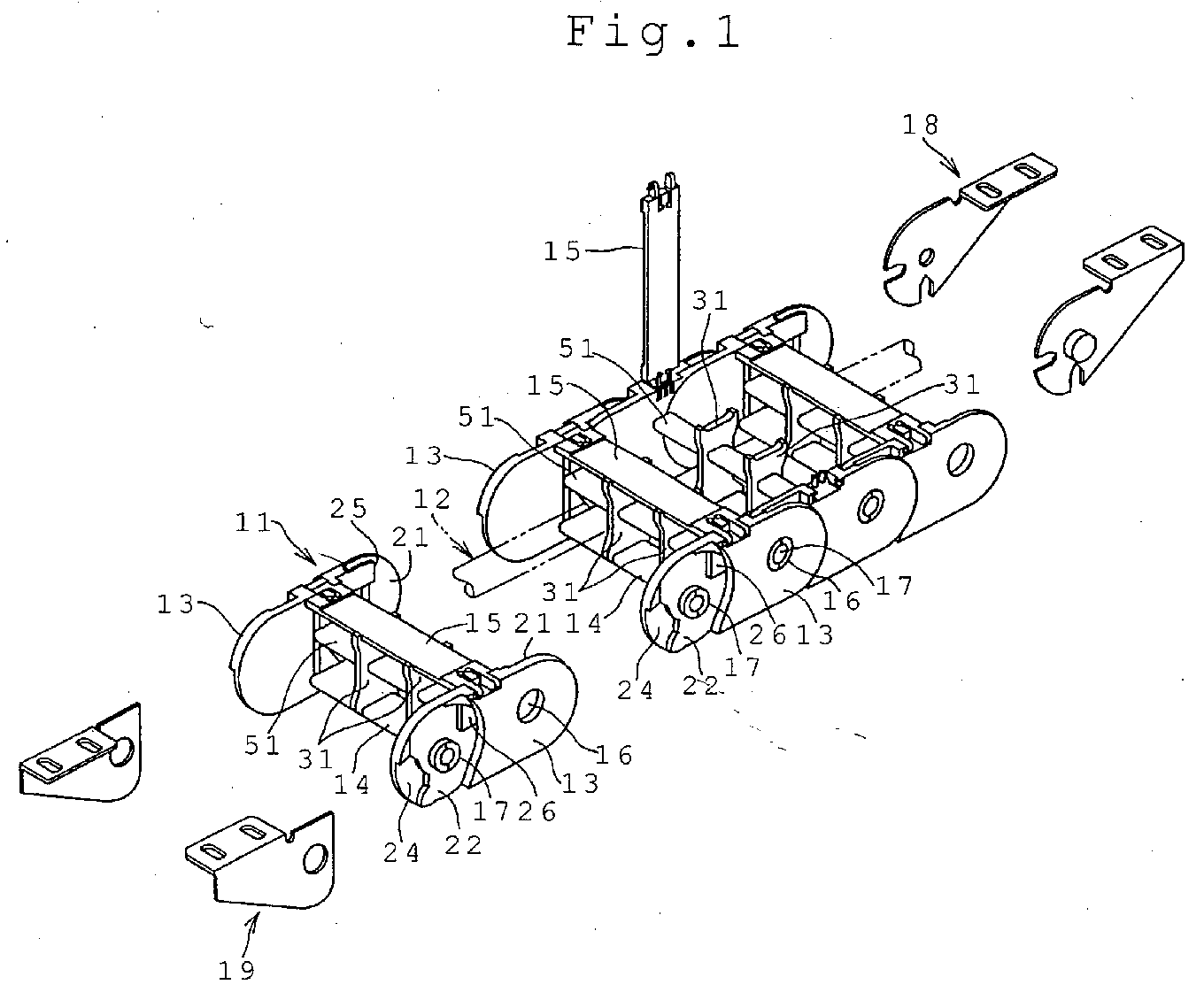
- FIG. 1
- is an exploded perspective view showing one example of a cable or the like protection and guide device according to the present invention.
- FIG. 2
- is a side view of a link body.
- FIG. 3
- is an end view of the link body taken along the line 3-3 in FIG. 2.
- FIG. 4
- is a perspective view of a state where a partitioning plate was separated from the link body.
- FIG. 5
- is an enlarged end view of a connecting portion between a partitioning plate and a connecting plate.
- FIG. 6
- is an enlarged cross-sectional view taken along the line 6-6 in FIG. 5.
- A better understanding of the invention will be had when reference is made to the detailed description of the invention and claims which follow hereinbelow.
- An example of a cable or the like protection and guide device according to the present invention will be described with reference to drawings below.
- This cable or the like protection and guide device comprises a plurality of
link bodies 11, as shown in FIG. 1. Theselink bodies 11 are arranged in a row and are articulably or bendably connected to theadjacent link bodies 11. The cable or the like 12 is inserted into theselink bodies 11. - Each
link body 11 includeslink plates 13 and connectingplates link plates 13 are arranged with a space in parallel with each other. The connecting plate 14 (hereinafter referred to as an inner circumferential side connecting plate to be differentiated from the other connecting plate 15) is arranged betweenlink plates 13 so as to bridge the inner circumferential sides of thelink plates 13. The inner circumferentialside connecting plate 14 and thelink plates 13 are composed of plastic and are integrally molded. The other connecting plate 15 (hereinafter referred to as an outer circumferential connecting plate) is also composed of the same plastic molded product, and is arranged between thelink plates 13 so as to bridge the outer circumferential sides of thelink plates 13. This outer circumferential connectingplate 15 is attached to thelink plates 13 in an openable manner. - The
link plate 13 has a shape of a cocoon when viewed from the side, as shown in FIG. 2. A front portion of thelink plate 13 is provided with apin hole 16. A rear portion of thelink plate 13 is integrally provided with apin 17 having a diameter corresponding to that of thepin hole 16. The front inner surface of thelink plate 13 is provided astepped wall 21 as shown in FIGS. 1 and 4. The rear edge of thestepped wall 21 on the front inner surface forms a partialcylindrical surface 21A, which is coaxial with thepin hole 16. Further, a rear outer surface of thelink plate 13 is provided with astepped wall 22. The front edge of the rear outer surface side steppedwall 22 forms a partial cylindrical surface 22A, which is coaxial with thepin 17. The inside space in the front inner surface side steppedwall 21 is slightly wider than the outside space in the rear outer surface side steppedwall 22. - The
respective link bodies 11 are connected by fitting the front inner surface side steppedwalls 21 to the rear outer surface side steppedwalls 22 of the front adjacent link bodies, and thepin hole 16 to thepin 17 of the frontadjacent link body 11, and by fitting the rear outer surface side steppedwalls 22 to the front inner surface side steppedwalls 21 of the adjacent link bodies and thepin 17 to thepin hole 16 of theadjacent link body 11, as shown in FIG. 1. Therefore, eachlink body 11 can be pivoted or articulated about thepin 17 with respect to theadjacent link body 11. - Into each
link body 11 is incorporated a mechanism for limiting a bend or pivot angle. This bend angle limiting mechanism has the same configuration as described in the specification of Japanese patent No. 3122491. When thelink bodies 11 are in a linear state, anarrow protrusion 23 on the front inner surface side steppedwall 21 of the link body shown in FIG. 2 contacts an upper end side of a fan-shapedrecess 24 on the rear outer surface side steppedwall 22 of theadjacent link body 11, and a flat limitingsurface 25 on a rear end of the rear outer surface side steppedwall 22 contacts a hook-shapedprotrusion 26 on the rear outer surface side steppedwall 22 of the frontadjacent link body 11. On the other hand, when thelink bodies 11 are in an articulation state, the arrow protrusion on the front inner surface side steppedwall 21 contacts a lower end side of the fan-shapedrecess 24 in the rear outer surface side steppedwall 22. - In this cable or the like protection and guide device, into each
link body 11 are incorporated partitioningplates 31, which define the inner space of thelink body 11 into a plurality of portions as shown in FIGS. 1, 3 and 4. Thepartitioning plate 31 is removably held by the inner circumferentialside connecting plate 14 and the outer circumferentialside connecting plate 15 at its upper and lower end. - The inner circumferential
side connecting plate 14 has a flat inner surface 14A without concave and convex portions, and includes connectingplate engagement portions 32 on its front and rear edges. As shown in FIGS. 3 and 4, a plurality of connectingplate engagement portions 32 are provided at constant intervals in the width direction of the inner circumferentialside connecting plate 14. As shown in FIG. 5, the connecting portion has a recess form in a trapezoid with an upper narrow side and a lower wide side when viewed from the front side of thelink body 11. The rear edge of the inner circumferentialside connecting plate 14 is provided connecting plate engagement portions having the same configuration linearly in parallel with said connecting plate engagement portions. Thepartitioning plate 31 has flat surfaces on both sides without concave and convex portions, and has agroove 33, which fits onto the inner surface 14A of the inner circumferentialside connecting plate 14 on the lower edge. Partitioningplate engagement portions 34 each have a form of protrusion and are formed at the front and rear portion of the lower edge of thepartitioning plate 31 by thegroove 33. The distance between the front and rear partitioningplate engagement portions 34 is slightly shorter than that of the connectingplate engagement portions 32 on the front and rear edges of the inner circumferentialside connecting plate 14. - Further, the outer circumferential
side connecting plate 15 has a flat inner surface 15A without concave and convex portions, and includes connectingplate engagement portions 37 on its front and rear edges. As shown in FIG. 3, a plurality of connectingplate engagement portions 37 are also provided at constant intervals in the width direction of the outer circumferentialside connecting plate 15. As shown in FIG. 5, the connecting portion has a recess form in a trapezoid with an upper wide side and a lower narrow side, which are opposite to the case of the connectingplate engagement portions 32 of the inner circumferentialside connecting plate 15. The rear edge of the inner circumferentialside connecting plate 14 is provided connecting plate engagement portions having the same configuration linearly in parallel with said connecting plate engagement portions. Thepartitioning plate 31 includes agroove 35, which fits to the inner surface 15A of the outer circumferentialside connecting plate 15, on the upper edge. A pair of partitioningplate engagement portions 36 are formed on the front and rear upper edge of the partitioning plate by thisgroove 35. The distance between the front and rear partitioningplate engagement portions 36 is slightly shorter than that of the connectingplate engagement portions 37 on the front and rear edges of the outer circumferentialside connecting plate 15. - The mounting of a
partitioning plate 31 on alink body 11 is performed by allowing acurved groove 33 on the lower edge to contact the inner surface 14A of an inner circumferentialside connecting plate 14 so that the front and rear partitioningplate engagement portions 34 on the lower edge are fitted to the front and rear connectingplate engagement portions 32 of the inner circumferentialside connecting plate 14, and by allowing acurved groove 35 on the upper edge to contact the outer surface 15A of an inner circumferentialside connecting plate 15 so that the front and rear partitioningplate engagement portions 36 on the upper edge are fitted to the front and rear connectingplate engagement portions 37 of the outer circumferentialside connecting plate 15. After the completion of the mounting, thepartitioning plate 31 is positioned between the connectingplates link body 11 is defined to a plurality portions. Since the distance between the partitioningplate engagement portions 34 is slightly shorter than the distance between the front and rear connectingplate engagement portions 32 of the inner circumferentialside connecting plate 14 and the distance between the partitioningplate engagement portions 36 is slightly shorter than the distance between the connectingplate engagement portions 37, as mentioned above, thepartitioning plate 31 or the connectingplates partitioning plate 31 and the connectingplates plate engagement portions 34 are fitted to the connectingplate engagement portions 32 and the upper partitioningplate engagement portions 36 are fitted to the connectingplate engagement portions 37. That is thepartitioning plates 31 sandwich the connectingplates link plate 21 and thepartitioning plate 31 or the distance between thepartitioning plates 31 can be freely adjusted by selecting the connectingplate engagement portions 37 in accordance with the diameters of the cables. - In a cable or the like protection and guide device according to the present invention a cable or the like such as a power source cable, which connects between a movable portion and a stationary portion in a tool machine, a cutting oil supply pipe or the like is inserted and this cable or the like protection and guide device is used for protecting this cable or the like and extending and contracting the cable or the like in accordance with the movement of the movable portion.
- The incorporation of the cable or the like 12 is performed by opening outer circumferential
side connecting plates 15 of all linkbodies 11, inserting the cable or the like 12 into inner space defined by partitioningplates 31 in the respective link bodies and closing the outer circumferentialside connecting plates 15. The mounting of the cable or the like protection and guide device on a tool machine is performed by pin-connecting a movable end fitting 18 and a fixed end fitting to the link bodies on both ends, connecting the movable end fitting 18 to a movable portion of the tool machine and the fixed end fitting 19 to a stationary portion and connecting this cable or the like protection and guide device to the earth through the movable end fitting 18 or the fixed end fitting 19. - When the movable portion of a tool machine is moved, the
link bodies 11 are brought into a bend or articulation state, or a linear state. Then the cable or the like 12 is also bent or becomes in a linear state while being contact with the inner surfaces 14A and 15A of the inner and outer circumferentialside connecting plates partitioning plates 31 and thelateral partitioning plate 51. In this case, thepartitioning plates 31 are connected to the partitioningplate engagement portions 34 on their front and rear edges and to the connectingplate engagement portions 32 on the front and rear edges of the connectingplates partitioning plates 31 to the connectingplates plates partitioning plate 31. Accordingly, even if the cable or the like 12 rubs against these surfaces, it is not damaged by rubbing and does not produce even wear powder. - Further, as shown in FIG. 6, the
partitioning plate 31 is positioned by engaging the partitioningplate engagement portion 34 with the connectingplate engagement portion 32 substantially vertically positioned on the front and rear edges of the inner circumferentialside connecting plate 14. Thus as long as the cable or the like 12 is not in a vertical state, it does not contact the connecting portion between the partitioningplate engagement portion 34 and the connectingplate engagement portion 32. Further, since the connectingplate engagement portion 37 of the outercircumferential connecting plate 15 is also substantially vertically disposed on its front and rear edge, the cable or the like 12 does not contact the connecting portion between the partitioningplate engagement portion 36 and the connectingplate engagement portion 37. Accordingly, the cable or the like 12 always contacts only the inner surfaces 14A, 15A of flat connectingplates partitioning plate 31, and it is not damaged by rubbing and does not produce wear powder due to the rubbing. - Further, since the partitioning
plate engagement portion 34 of thepartitioning plate 31 and the connectingplate engagement portion 32 of the inner circumferentialside connecting plate 14 are formed in a trapezoidal shape with an upper narrow side and a lower wide side, and the partitioningplate engagement portion 36 of thepartitioning plate 31 and the connectingplate engagement portion 37 of the inner circumferentialside connecting plate 15 are formed in a trapezoidal shape with an lower narrow side and an upper wide side so as to be pulled out, even if this cable or the like protection and guide device is operated at high speed and high frequency, thepartitioning plates 31 are not disconnected from the connectingplates - In this cable or the like protection and guide device, when the cables or the like 12 are disposed on vertical multi-steps, a
lateral partitioning plate 51, which penetrates through thepartitioning plate 31, is incorporated, as shown in FIGS. 1 and 4. Thus thepartitioning plate 31 is provided with a lateral partitioning plate-insertinghole 52. The lateral partitioning plate-insertinghole 52 has the shape of an oval. Thelateral partitioning plate 51 has a hollow or solid form having an oval cross-section corresponding to the shape of the lateral partitioning plate-insertinghole 52, and is made of metal or plastic or the like. The mounting of thelateral partitioning plate 51 onto thepartitioning plate 31 is performed by press-fitting thelateral partitioning plate 51 into the lateral partitioning plate-insertinghole 52. This mounting of thelateral partitioning plate 51 further separates the respective cable or the like accommodation spaces defined by therespective link plates 13 and thepartitioning plates 31 into two portions. - Since such a lateral partitioning plate support structure is positioned by press-fitting the
lateral partitioning plate 51 to the lateral partitioning plate-insertinghole 52 in thepartitioning plate 31, the surface of thelateral partitioning plate 51 can be formed flatly. Thus, when thelink body 11 became in an articulation state or linear state, even if the cable or the like 12 slides while contacting thepartitioning plate 31 and thelateral partitioning plate 51, the cable or the like 12 is not damaged by rubbing and does not generate wear powder. - It is noted that in the above-explained example, the forced positioning of the connecting
plate 31 was performed by providingplate engagement portions 32 in the inner and outer circumferentialside connecting plates plate engagement portions 34 of the upper and lower portions of thepartitioning plate 31 to each connectingplate engagement portion 32. However, connecting plate engagement portions and partitioning plate engagement portions may be provided in only one of the connectingplates partitioning plate 31 in accordance with a use or arrangement environment. - Further, although a plurality of connecting
plate engagement portions 32 were provided in the width directions of the connectingplates plate engagement portion 32 in the connectingplates plate engagement portion 34 of thepartitioning plate 31 may be formed as a recess, which is opposite to the case explained above. - As mentioned above, in the cable or the like protection and guide device according to
claim 1, the connecting plate includes connecting plate engagement portions formed at non-contact positions of a front end surface and a rear end surface, and said partitioning plate includes a pair of front and rear partitioning plate engagement portions formed on at least the articulation inner circumferential side and which sandwich said connecting plate engagement portions when engaged therewith. Accordingly, the inner surface of the connecting plate and the side surface of the partitioning plate can be formed flatly, and a cable or the like is not rubbing-damaged. Further, the cable or the like does not produce wear powder. Therefore, even if the cable or the like protection and guide device is operated at high speed and high frequency, it can possess high durability and reliability, and even in a clean environment the device can be used. - According to the cable or the like protection and guide device of claim 2, in the cable or the like protection and guide device of claim 2, the connecting plate engagement portions are provided along the width direction of the connecting plate and with a space from each other. Accordingly, in accordance with the accommodation space for the cable or the like, that is the size of the cable or the like, the space between the partitioning plate and the link plate or the space between the partitioning plates can be changed.
- According to the cable or the like protection and guide device of
claim 3, in the cable or the like protection and guide device ofclaim 1, the connecting plate engagement portion and the partitioning plate engagement portion are formed in a trapezoid with an upper narrow side and a lower wide side. Thus, since the partitioning plate is strongly connected to the connecting plate whereby it is not disconnected, higher durability and reliability can be obtained. -
- 11
- Link body
- 12
- Cable or the like
- 13
- Link plate
- 14
- Inner circumferential side connecting plate / Connecting plate
- 14A
- Inner surface
- 15
- Outer circumferential side connecting plate / Connecting plate
- 15A
- Inner surface
- 16
- Pin hole
- 17
- Pin
- 18
- Movable end fitting
- 19
- Fixed end fitting
- 21
- Stepped wall
- 21A
- Partial cylindrical surface
- 22
- Stepped wall
- 22A
- Partial cylindrical surface
- 23
- Arrow protrusion
- 24
- Fan-shaped recess
- 25
- Flat limiting surface
- 26
- Hook-shaped protrusion
- 31
- Partitioning plate
- 32
- Connecting plate engagement portion
- 33
- Groove
- 34
- Partitioning plate engagement portion
- 35
- Groove
- 36
- Partitioning plate engagement portion
- 37
- Connecting plate engagement portion
- 51
- Lateral partitioning plate
- 52
- Lateral partitioning plate-inserting hole
Claims (7)
- Cable or the like protection and guide device in which a plurality of link bodies (11), each comprising a pair of link plates (13) spaced on both sides of the cable or the like (12), connecting plates (14, 15) each laterally bridged on the articulation outer circumferential and inner circumferential sides of the link plates (13), and a partitioning plate (31) facing the link plates (13) and supported by at least the articulation inner circumferential side connecting plate (14), are articulably connected in the longitudinal direction of the device with said cable or the like (12) inserted therein, characterized in that
the connecting plate (14, 15) includes connecting plate engagement portions (32, 37) formed at non-contact positions of a front end surface and a rear end surface, and the partitioning plate (31) includes a pair of front and rear partitioning plate engagement portions (34, 36) formed on at least the articulation inner circumferential side and which sandwich said connecting plate engagement portions (32, 37) when engaged therewith. - Cable or the like protection and guide device according to claim 1, characterized in that the connecting plate engagement portions (32, 37) are provided along the width direction of the connecting plate (14, 15) and with a space from each other.
- Cable or the like protection and guide device according to claim 1 or 2, characterized in that said connecting plate engagement portion (32, 37) and the partitioning plate engagement portion (34, 36) are formed in a trapezoid with an upper narrow side and a lower wide side.
- Cable or the like protection and guide device according to one of claims 1 to 3, characterized in that the connecting plate engagement portions (32, 37)are provided at constant intervals in the width direction of the connecting plate (14, 15).
- Cable or the like protection and guide device according to one of claims 1 to 4, characterized in that the link plates (13) and the connecting plates (14, 15) are composed of plastic.
- Cable or the like protection and guide device according to one of claims 1 to 5, characterized in that the link plates (13) and the inner circumferential connecting plate (14) are integrally molded.
- Cable or the like protection and guide device according to one of claims 1 to 6, characterized in that the distance between the front and rear end partitioning plate engagement portions (34, 36) is slightly shorter than that of the connecting plate engagement portions (32, 37) on the front and rear edges of the outer circumferential side connecting plate (14, 15).
Applications Claiming Priority (2)
| Application Number | Priority Date | Filing Date | Title |
|---|---|---|---|
| JP2003123853 | 2003-04-28 | ||
| JP2003123853A JP3717168B2 (en) | 2003-04-28 | 2003-04-28 | Cable protection guide device |
Publications (3)
| Publication Number | Publication Date |
|---|---|
| EP1473487A2 true EP1473487A2 (en) | 2004-11-03 |
| EP1473487A3 EP1473487A3 (en) | 2005-04-27 |
| EP1473487B1 EP1473487B1 (en) | 2008-05-21 |
Family
ID=32985563
Family Applications (1)
| Application Number | Title | Priority Date | Filing Date |
|---|---|---|---|
| EP04008304A Expired - Lifetime EP1473487B1 (en) | 2003-04-28 | 2004-04-06 | Cable or the like protection and guide device |
Country Status (4)
| Country | Link |
|---|---|
| US (1) | US7013630B2 (en) |
| EP (1) | EP1473487B1 (en) |
| JP (1) | JP3717168B2 (en) |
| DE (1) | DE602004013875D1 (en) |
Cited By (5)
| Publication number | Priority date | Publication date | Assignee | Title |
|---|---|---|---|---|
| TWI487854B (en) * | 2010-04-02 | 2015-06-11 | Tsubakimoto Chain Co | Cables and the like protecting and guiding multi-joint supporting member |
| TWI503495B (en) * | 2011-09-26 | 2015-10-11 | Denso Wave Inc | Protective guide for cables and bracket used for the protective guide |
| CN109340314A (en) * | 2018-09-12 | 2019-02-15 | 郑州云海信息技术有限公司 | A tank chain structure for server cable fixing |
| CN110454548A (en) * | 2019-09-06 | 2019-11-15 | 无锡德斯普拖链技术有限公司 | A drag chain link structure |
| CN110630690A (en) * | 2019-10-15 | 2019-12-31 | 深圳市华南天城机床配件有限公司 | A metal and plastic composite long-distance anti-collapse drag chain |
Families Citing this family (11)
| Publication number | Priority date | Publication date | Assignee | Title |
|---|---|---|---|---|
| JP4420934B2 (en) | 2007-03-29 | 2010-02-24 | 株式会社椿本チエイン | Cable protection guide device |
| JP4751862B2 (en) | 2007-08-08 | 2011-08-17 | 株式会社椿本チエイン | Cable protection guide device |
| KR100890197B1 (en) | 2007-12-17 | 2009-03-25 | 씨피시스템(주) | Rotating Body Cable Protector |
| NL2003546A (en) * | 2008-10-21 | 2010-04-22 | Asml Netherlands Bv | Lithographic apparatus comprising an assembly of a line carrier with low-friction cables, hoses or the like and such an assembly in general. |
| JP5618933B2 (en) * | 2011-07-25 | 2014-11-05 | 株式会社椿本チエイン | Cable protection guide device |
| US8733077B2 (en) * | 2012-10-04 | 2014-05-27 | Hewlett-Packard Development Company, L.P. | Transmission line guide chains and dividers for transmission line guide chains |
| AU352878S (en) * | 2013-12-03 | 2013-12-11 | Acteuro Ltd | Cable handler |
| JP6421109B2 (en) * | 2015-11-16 | 2018-11-07 | 株式会社椿本チエイン | Cable protection guide device and guide rail |
| DE202020105039U1 (en) * | 2020-09-01 | 2021-10-04 | Igus Gmbh | Energy guiding chain with cable-friendly interior division as well as chain link and frame module for this |
| US11326672B2 (en) * | 2020-09-23 | 2022-05-10 | Craig Louis Althen | Continuously variable, non-friction, drive chain |
| KR102630152B1 (en) * | 2020-11-23 | 2024-01-29 | (주)한신체인 | Robochain |
Citations (2)
| Publication number | Priority date | Publication date | Assignee | Title |
|---|---|---|---|---|
| JPH03122491A (en) | 1989-10-04 | 1991-05-24 | Kawasaki Steel Corp | Repairing method using flame fusion coating for refractory of molten metal container |
| JP2000120807A (en) | 1998-08-10 | 2000-04-28 | Harmo Soken:Kk | Cable hose protecting and guiding chain |
Family Cites Families (7)
| Publication number | Priority date | Publication date | Assignee | Title |
|---|---|---|---|---|
| DE9014027U1 (en) | 1990-10-09 | 1990-12-13 | Kabelschlepp GmbH, 57074 Siegen | Energy chain |
| DE4105652A1 (en) * | 1991-02-22 | 1992-09-03 | Kabelschlepp Gmbh | POWER SUPPLY CHAIN |
| US5108350A (en) * | 1991-03-06 | 1992-04-28 | A&A Manufacturing Co., Inc. | Conduit carrier chain |
| JP2507194Y2 (en) * | 1991-07-31 | 1996-08-14 | 株式会社椿本チエイン | Internal partition structure of cable drag chain |
| DE19703410A1 (en) * | 1997-01-30 | 1998-08-06 | Kabelschlepp Gmbh | Chain link with insertable dividers |
| DE29921667U1 (en) | 1999-12-09 | 2001-04-19 | Kabelschlepp GmbH, 57074 Siegen | Chain link with dividers |
| DE20005042U1 (en) | 2000-03-20 | 2000-09-07 | Igus Spritzgußteile für die Industrie GmbH, 51147 Köln | Energy chain |
-
2003
- 2003-04-28 JP JP2003123853A patent/JP3717168B2/en not_active Expired - Fee Related
-
2004
- 2004-03-12 US US10/799,194 patent/US7013630B2/en not_active Expired - Lifetime
- 2004-04-06 DE DE602004013875T patent/DE602004013875D1/en not_active Expired - Lifetime
- 2004-04-06 EP EP04008304A patent/EP1473487B1/en not_active Expired - Lifetime
Patent Citations (2)
| Publication number | Priority date | Publication date | Assignee | Title |
|---|---|---|---|---|
| JPH03122491A (en) | 1989-10-04 | 1991-05-24 | Kawasaki Steel Corp | Repairing method using flame fusion coating for refractory of molten metal container |
| JP2000120807A (en) | 1998-08-10 | 2000-04-28 | Harmo Soken:Kk | Cable hose protecting and guiding chain |
Cited By (5)
| Publication number | Priority date | Publication date | Assignee | Title |
|---|---|---|---|---|
| TWI487854B (en) * | 2010-04-02 | 2015-06-11 | Tsubakimoto Chain Co | Cables and the like protecting and guiding multi-joint supporting member |
| TWI503495B (en) * | 2011-09-26 | 2015-10-11 | Denso Wave Inc | Protective guide for cables and bracket used for the protective guide |
| CN109340314A (en) * | 2018-09-12 | 2019-02-15 | 郑州云海信息技术有限公司 | A tank chain structure for server cable fixing |
| CN110454548A (en) * | 2019-09-06 | 2019-11-15 | 无锡德斯普拖链技术有限公司 | A drag chain link structure |
| CN110630690A (en) * | 2019-10-15 | 2019-12-31 | 深圳市华南天城机床配件有限公司 | A metal and plastic composite long-distance anti-collapse drag chain |
Also Published As
| Publication number | Publication date |
|---|---|
| US20040237498A1 (en) | 2004-12-02 |
| US7013630B2 (en) | 2006-03-21 |
| EP1473487B1 (en) | 2008-05-21 |
| EP1473487A3 (en) | 2005-04-27 |
| DE602004013875D1 (en) | 2008-07-03 |
| JP3717168B2 (en) | 2005-11-16 |
| JP2004324851A (en) | 2004-11-18 |
Similar Documents
| Publication | Publication Date | Title |
|---|---|---|
| EP1473487B1 (en) | Cable or the like protection and guide device | |
| EP1351362B1 (en) | Protective guide for flexible elongated article | |
| US4392344A (en) | Chain-link cable carrier | |
| EP1922161B1 (en) | Hydraulic tool working head | |
| EP1030426B1 (en) | Cable chain | |
| KR20010072759A (en) | Line guidance device | |
| TWI392816B (en) | Bending cable protection guide | |
| JP6421109B2 (en) | Cable protection guide device and guide rail | |
| JP5709799B2 (en) | Cable protection guide member | |
| EP1068139B1 (en) | Conveyor mat | |
| EP1291996A1 (en) | Protective guide for cables and the like | |
| EP3421410B1 (en) | Engagement chain and movable body movement device | |
| US7150206B2 (en) | Cable or the like protection and guide device | |
| US6578350B2 (en) | Energy guiding chain | |
| US20040188128A1 (en) | Cable or the like protection and guide device | |
| JPH02186146A (en) | Closed type cable support chain | |
| CN114502858B (en) | Engagement chain and movable body moving device | |
| KR20190050738A (en) | Cable chain | |
| KR100377842B1 (en) | Power supply chain | |
| EP1629219B1 (en) | Cable/hose haulage chain | |
| KR101360859B1 (en) | Non-warping chain link | |
| CN115136431A (en) | Long article protection and guide device | |
| TW202611415A (en) | Multi-joint support structure, flat conveyor device | |
| KR200296785Y1 (en) | Device for curving track frame for cable trolley | |
| EP2520467A1 (en) | Power feeding apparatus and fixing structure |
Legal Events
| Date | Code | Title | Description |
|---|---|---|---|
| PUAI | Public reference made under article 153(3) epc to a published international application that has entered the european phase |
Free format text: ORIGINAL CODE: 0009012 |
|
| AK | Designated contracting states |
Kind code of ref document: A2 Designated state(s): AT BE BG CH CY CZ DE DK EE ES FI FR GB GR HU IE IT LI LU MC NL PL PT RO SE SI SK TR |
|
| AX | Request for extension of the european patent |
Extension state: AL HR LT LV MK |
|
| PUAL | Search report despatched |
Free format text: ORIGINAL CODE: 0009013 |
|
| AK | Designated contracting states |
Kind code of ref document: A3 Designated state(s): AT BE BG CH CY CZ DE DK EE ES FI FR GB GR HU IE IT LI LU MC NL PL PT RO SE SI SK TR |
|
| AX | Request for extension of the european patent |
Extension state: AL HR LT LV MK |
|
| 17P | Request for examination filed |
Effective date: 20050416 |
|
| AKX | Designation fees paid |
Designated state(s): DE FR GB IT |
|
| GRAP | Despatch of communication of intention to grant a patent |
Free format text: ORIGINAL CODE: EPIDOSNIGR1 |
|
| GRAS | Grant fee paid |
Free format text: ORIGINAL CODE: EPIDOSNIGR3 |
|
| RAP1 | Party data changed (applicant data changed or rights of an application transferred) |
Owner name: TSUBAKIMOTO CHAIN CO. |
|
| RIN1 | Information on inventor provided before grant (corrected) |
Inventor name: KOMIYA, SHOICHIRO |
|
| GRAA | (expected) grant |
Free format text: ORIGINAL CODE: 0009210 |
|
| AK | Designated contracting states |
Kind code of ref document: B1 Designated state(s): DE FR GB IT |
|
| REG | Reference to a national code |
Ref country code: GB Ref legal event code: FG4D |
|
| REF | Corresponds to: |
Ref document number: 602004013875 Country of ref document: DE Date of ref document: 20080703 Kind code of ref document: P |
|
| PLBE | No opposition filed within time limit |
Free format text: ORIGINAL CODE: 0009261 |
|
| STAA | Information on the status of an ep patent application or granted ep patent |
Free format text: STATUS: NO OPPOSITION FILED WITHIN TIME LIMIT |
|
| 26N | No opposition filed |
Effective date: 20090224 |
|
| GBPC | Gb: european patent ceased through non-payment of renewal fee |
Effective date: 20090406 |
|
| REG | Reference to a national code |
Ref country code: FR Ref legal event code: ST Effective date: 20091231 |
|
| PG25 | Lapsed in a contracting state [announced via postgrant information from national office to epo] |
Ref country code: FR Free format text: LAPSE BECAUSE OF NON-PAYMENT OF DUE FEES Effective date: 20091222 Ref country code: GB Free format text: LAPSE BECAUSE OF NON-PAYMENT OF DUE FEES Effective date: 20090406 |
|
| PGFP | Annual fee paid to national office [announced via postgrant information from national office to epo] |
Ref country code: IT Payment date: 20190419 Year of fee payment: 16 Ref country code: DE Payment date: 20190326 Year of fee payment: 16 |
|
| REG | Reference to a national code |
Ref country code: DE Ref legal event code: R119 Ref document number: 602004013875 Country of ref document: DE |
|
| PG25 | Lapsed in a contracting state [announced via postgrant information from national office to epo] |
Ref country code: DE Free format text: LAPSE BECAUSE OF NON-PAYMENT OF DUE FEES Effective date: 20201103 |
|
| PG25 | Lapsed in a contracting state [announced via postgrant information from national office to epo] |
Ref country code: IT Free format text: LAPSE BECAUSE OF NON-PAYMENT OF DUE FEES Effective date: 20200406 |