EP1473452A2 - Combustion control system and method for spark-ignition internal combustion engine - Google Patents
Combustion control system and method for spark-ignition internal combustion engine Download PDFInfo
- Publication number
- EP1473452A2 EP1473452A2 EP04010105A EP04010105A EP1473452A2 EP 1473452 A2 EP1473452 A2 EP 1473452A2 EP 04010105 A EP04010105 A EP 04010105A EP 04010105 A EP04010105 A EP 04010105A EP 1473452 A2 EP1473452 A2 EP 1473452A2
- Authority
- EP
- European Patent Office
- Prior art keywords
- autoignition
- timing
- knock
- engine
- combustion
- Prior art date
- Legal status (The legal status is an assumption and is not a legal conclusion. Google has not performed a legal analysis and makes no representation as to the accuracy of the status listed.)
- Withdrawn
Links
Images


Classifications
-
- F—MECHANICAL ENGINEERING; LIGHTING; HEATING; WEAPONS; BLASTING
- F02—COMBUSTION ENGINES; HOT-GAS OR COMBUSTION-PRODUCT ENGINE PLANTS
- F02D—CONTROLLING COMBUSTION ENGINES
- F02D35/00—Controlling engines, dependent on conditions exterior or interior to engines, not otherwise provided for
- F02D35/02—Controlling engines, dependent on conditions exterior or interior to engines, not otherwise provided for on interior conditions
- F02D35/027—Controlling engines, dependent on conditions exterior or interior to engines, not otherwise provided for on interior conditions using knock sensors
-
- F—MECHANICAL ENGINEERING; LIGHTING; HEATING; WEAPONS; BLASTING
- F02—COMBUSTION ENGINES; HOT-GAS OR COMBUSTION-PRODUCT ENGINE PLANTS
- F02D—CONTROLLING COMBUSTION ENGINES
- F02D35/00—Controlling engines, dependent on conditions exterior or interior to engines, not otherwise provided for
- F02D35/02—Controlling engines, dependent on conditions exterior or interior to engines, not otherwise provided for on interior conditions
- F02D35/023—Controlling engines, dependent on conditions exterior or interior to engines, not otherwise provided for on interior conditions by determining the cylinder pressure
- F02D35/024—Controlling engines, dependent on conditions exterior or interior to engines, not otherwise provided for on interior conditions by determining the cylinder pressure using an estimation
-
- F—MECHANICAL ENGINEERING; LIGHTING; HEATING; WEAPONS; BLASTING
- F02—COMBUSTION ENGINES; HOT-GAS OR COMBUSTION-PRODUCT ENGINE PLANTS
- F02D—CONTROLLING COMBUSTION ENGINES
- F02D35/00—Controlling engines, dependent on conditions exterior or interior to engines, not otherwise provided for
- F02D35/02—Controlling engines, dependent on conditions exterior or interior to engines, not otherwise provided for on interior conditions
- F02D35/025—Controlling engines, dependent on conditions exterior or interior to engines, not otherwise provided for on interior conditions by determining temperatures inside the cylinder, e.g. combustion temperatures
- F02D35/026—Controlling engines, dependent on conditions exterior or interior to engines, not otherwise provided for on interior conditions by determining temperatures inside the cylinder, e.g. combustion temperatures using an estimation
-
- F—MECHANICAL ENGINEERING; LIGHTING; HEATING; WEAPONS; BLASTING
- F02—COMBUSTION ENGINES; HOT-GAS OR COMBUSTION-PRODUCT ENGINE PLANTS
- F02P—IGNITION, OTHER THAN COMPRESSION IGNITION, FOR INTERNAL-COMBUSTION ENGINES; TESTING OF IGNITION TIMING IN COMPRESSION-IGNITION ENGINES
- F02P5/00—Advancing or retarding ignition; Control therefor
- F02P5/04—Advancing or retarding ignition; Control therefor automatically, as a function of the working conditions of the engine or vehicle or of the atmospheric conditions
- F02P5/145—Advancing or retarding ignition; Control therefor automatically, as a function of the working conditions of the engine or vehicle or of the atmospheric conditions using electrical means
- F02P5/15—Digital data processing
- F02P5/152—Digital data processing dependent on pinking
- F02P5/1522—Digital data processing dependent on pinking with particular means concerning an individual cylinder
-
- F—MECHANICAL ENGINEERING; LIGHTING; HEATING; WEAPONS; BLASTING
- F02—COMBUSTION ENGINES; HOT-GAS OR COMBUSTION-PRODUCT ENGINE PLANTS
- F02D—CONTROLLING COMBUSTION ENGINES
- F02D41/00—Electrical control of supply of combustible mixture or its constituents
- F02D41/02—Circuit arrangements for generating control signals
- F02D41/14—Introducing closed-loop corrections
- F02D41/1401—Introducing closed-loop corrections characterised by the control or regulation method
- F02D2041/1412—Introducing closed-loop corrections characterised by the control or regulation method using a predictive controller
-
- F—MECHANICAL ENGINEERING; LIGHTING; HEATING; WEAPONS; BLASTING
- F02—COMBUSTION ENGINES; HOT-GAS OR COMBUSTION-PRODUCT ENGINE PLANTS
- F02D—CONTROLLING COMBUSTION ENGINES
- F02D41/00—Electrical control of supply of combustible mixture or its constituents
- F02D41/02—Circuit arrangements for generating control signals
- F02D41/14—Introducing closed-loop corrections
- F02D41/1401—Introducing closed-loop corrections characterised by the control or regulation method
- F02D2041/1433—Introducing closed-loop corrections characterised by the control or regulation method using a model or simulation of the system
-
- G—PHYSICS
- G01—MEASURING; TESTING
- G01N—INVESTIGATING OR ANALYSING MATERIALS BY DETERMINING THEIR CHEMICAL OR PHYSICAL PROPERTIES
- G01N33/00—Investigating or analysing materials by specific methods not covered by groups G01N1/00 - G01N31/00
- G01N33/26—Oils; Viscous liquids; Paints; Inks
- G01N33/28—Oils, i.e. hydrocarbon liquids
- G01N33/2829—Mixtures of fuels
-
- Y—GENERAL TAGGING OF NEW TECHNOLOGICAL DEVELOPMENTS; GENERAL TAGGING OF CROSS-SECTIONAL TECHNOLOGIES SPANNING OVER SEVERAL SECTIONS OF THE IPC; TECHNICAL SUBJECTS COVERED BY FORMER USPC CROSS-REFERENCE ART COLLECTIONS [XRACs] AND DIGESTS
- Y02—TECHNOLOGIES OR APPLICATIONS FOR MITIGATION OR ADAPTATION AGAINST CLIMATE CHANGE
- Y02T—CLIMATE CHANGE MITIGATION TECHNOLOGIES RELATED TO TRANSPORTATION
- Y02T10/00—Road transport of goods or passengers
- Y02T10/10—Internal combustion engine [ICE] based vehicles
- Y02T10/40—Engine management systems
Definitions
- the present invention relates to a combustion control system and method for a spark-ignition internal combustion engine.
- a spark-ignition internal combustion engine is generally operated at a higher compression ratio for improvement in thermal efficiency, but such a performance improvement can be affected by engine knock.
- a knock control system that monitors the occurrence of engine knock with a knock sensor and performs feedback control on ignition timing has been proposed and already come into use so as to prevent engine knock while maximizing engine thermal efficiency.
- the engine knock could be prevented more assuredly by not only carrying out a knock avoidance operation upon detection of the engine knock but also predicting knock occurrence according to a simulation model.
- the ignition timing is commonly set using a prescribed ignition-timing map with reference to engine speed and power and then adjusted on detection of the engine knock.
- a multiplicity of actual vehicle experiments must be conducted to prepare the ignition-timing map, and the number of experiments required to prepare the ignition-timing map becomes increased with the recent application of variable mechanisms including a variable valve mechanism and an exhaust gas recirculation mechanism. This results in higher cost and greater facility for engine development. It can be however expected that the prediction of knock occurrence by a simulation model will allow an omission of many or at least some of the experiments for preparation of the ignition-timing map to thereby provide a great advantage in engine development.
- Japanese Laid-Open Patent Publication No. 7-332149 proposes a combustion control device for an internal combustion engine, capable of predicting the autoignition timing of an unburned air-fuel mixture, or equivalently, the occurrence of engine knock and controlling combustion so as to avoid the engine knock in accordance with the prediction.
- a combustion control system for a spark-ignition internal combustion engine the system being configured to: detect engine operating conditions; predict, based on the detected engine operating conditions, autoignition timing of an end gas and an amount of heat released due to autoignition of the end gas; and control combustion to establish such a relationship between the autoignition timing and the amount of heat released due to the autoignition as to give a knock intensity not higher than a specified intensity limit.
- a combustion control system for a spark-ignition internal combustion engine the system being configured to: detect engine operating conditions; predict, based on the detected engine operating conditions, an autoignition timing of an end gas and an amount of heat released due to autoignition of the end gas; calculate a knock intensity from the autoignition timing and the amount of heat released due to the autoignition; and control combustion in the engine in such a manner that the knock intensity is lower than or equal to a specified intensity limit.
- a combustion control method for a spark-ignition internal combustion engine comprising: detecting engine operating conditions; predicting, based on the detected engine operating conditions, autoignition timing of an end gas and an amount of heat released due to autoignition of the end gas; and controlling combustion to establish such a relationship between the autoignition timing and the amount of heat released due to the autoignition as to give a knock intensity not higher than a specified intensity limit.
- a combustion control method for a spark-ignition internal combustion engine comprising: detecting engine operating conditions; predicting, based on the detected engine operating conditions, autoignition timing of an end gas and an amount of heat released due to autoignition of the end gas; calculating a knock intensity from the autoignition timing and the amount of heat released due to the autoignition; and controlling combustion in the engine in such a manner that the knock intensity is lower than or equal to a specified intensity limit.
- FIG. 1 is a schematic view of a spark-ignition internal combustion engine according to one exemplary embodiment of the present invention.
- FIG. 2 is a flowchart for controlling the operations of the spark-ignition engine according to one exemplary embodiment of the present invention.
- FIGS. 3A and 3B are diagrams of a two-zone combustion model.
- FIG. 4A and 4B are graphs showing a relationship between knock intensity and autoignition timing and heat release amount under certain engine operating conditions.
- FIG. 5 is a graph showing variations in the autoignited mixture fraction with respect to the crank angle at the knock occurrence under different octane-number conditions.
- FIG. 6 is a graph showing variations in the autoignited mixture fraction with respect to the crank angle at the knock occurrence under different octane-number and compression-ratio conditions.
- FIG. 7 is a graph showing variations in the autoignited mixture faction with respect to the crank angle at the knock occurrence under different engine-speed conditions.
- FIGS. 8A and 8B are diagrams of how to estimate a trace knock point on the prediction of autoignition timing and heat release amount according to one exemplary embodiment of the present invention.
- FIG. 9 is a graph showing the validity of a combustion simulation according to another exemplary embodiment of the present invention.
- FIG. 1 is a schematic view of a spark-ignition internal combustion engine according to the first embodiment.
- the engine has cylinder head 1, cylinder block 2, piston 3, combustion chamber 4 (defined by cylinder head 1, cylinder block 2 and piston 3), intake valve 5, valve timing control mechanism 5b, exhaust valve 6, intake port 7, exhaust port 8, fuel injection valve 9 and spark plug 10.
- Combustion chamber 4 is supplied with fresh air through intake valve 5 and intake port 7.
- the open and close timing of intake valve 5 is adjusted with valve timing control mechanism 5b.
- Fuel injection valve 9 is disposed in intake port 7 to inject an appropriate amount of fuel and thereby form a flammable air-fuel mixture in combustion chamber 4.
- the air-fuel mixture is ignited by spark plug 10, and the burned product gas is discharged out of combustion chamber 4 through exhaust valve 6 and exhaust port 8.
- the engine further includes engine control unit (ECU) 11 and various sensors, such as accelerator opening sensor 12, coolant temperature sensor 13, crank angle sensor 14, air flow meter 15, intake temperature sensor 16 and throttle sensor 17.
- ECU engine control unit
- sensors 12 to 17 are connected to ECU 11 so that ECU 11 controls the operations of the engine integratedly in response to signals from sensors 12 to 17.
- FIG. 2 is a flowchart for controlling the operations of the engine according to the first embodiment.
- ECU 11 first receives the signal from sensors 12 to 17 to detect engine operating conditions including an accelerator opening, a coolant temperature, a crank angle (engine speed), an intake air amount, an intake air temperature and a throttle opening. By required signal processing and computing, ECU 11 estimates an effective compression ratio and valve timing for controlling valve timing control mechanism 5b, fuel injection valve 9 and spark plug 10. ECU 11 also estimates an air-fuel ratio, a residual gas rate and temperature and pressure in combustion chamber 4 at the close timing of intake valve 5. ECU 11 does a cycle simulation using the above estimated status values as initial parameters to predict autoignition timing of an end gas (unburned air-fuel mixture) and an amount of heat released due to autoignition of the end gas (hereinafter referred to as an "autoignition heat release amount").
- the cycle simulation is done according to a two-zone combustion model and an autoignition model in the first embodiment.
- ECU 11 calculates a knock intensity from the predicted autoignition timing and heat release amount.
- ECU 11 further calculates, from the knock intensity, a trace knock point at which trace knock occurs and a minimum ignition advance for the best torque (MBT), i.e., ignition timing that presents optimal engine torque and specific fuel comsumption.
- MBT best torque
- ECU 11 Based on the trace knock point and MBT, ECU 11 performs combustion control in such a manner that the knock intensity becomes equal to or smaller than a trace knock level (an allowable limit of engine knock).
- ECU 11 gives feedback on the trace knock point and MBT to set a heat release pattern in the cycle simulation.
- FIGS. 3A and 3B diagrams of the two-zone combustion model, showing combustion chamber 4 when viewed from above.
- the flame front of a combustion flame is indicated by a heavy line
- the position of spark plug 10 is indicated by a cross.
- combustion flame propagates spherically from the position of spark plug 10 as shown in FIGS. 3A and 3B, so as to divide combustion chamber 4 by the flame front into two zones: a burned zone in which the burned air-fuel mixture exists and an unburned zone in which the end gas exists.
- a burned zone in which the burned air-fuel mixture exists
- an unburned zone in which the end gas exists.
- the mass and enthalpy of such a thermodynamic system is transferred from the unburned zone into the burned zone.
- the unburned zone becomes compressed to a high-temperature and high-pressure state under the influence of the heat release and thermal expansion in the burned zone.
- the autoignition model is then applied to the history of the end gas temperature and pressure data in the cycle simulation.
- the occurrence of engine knock is judged in the case where autoignition occurs in the unburned zone before the combustion flame has propagated throughout combustion chamber 4.
- the autoignition timing and heat release amount are derived upon judging the knock occurrence.
- Equation (1) The energy conservation in the burned and unburned zones per unit time are given by the equations (1) and (2), respectively: where m is the mass of the air-fuel mixture, x is the mass fraction, u is the specific internal energy, i.e., the differential coefficient of internal energy, p is the pressure, V is the volume, dx is the change in mass fraction, h is the specific enthalpy and Q is the amount of heat transfer.
- the third term mdx b h u of the equations (1) and (2) represents the amount of enthalpy transferred from the unburned zone to the burned zone via the flame front
- the fourth terms dQ b,wall and dQ u,wall of the equations (1) and (2) represent the amounts of heat transferred from the wall of combustion chamber 4 into the burned zone and the unburned zone, respectively.
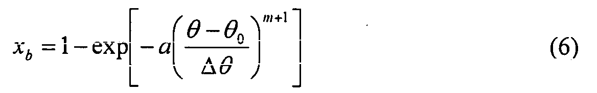
- the mass fraction x b of the burned gas is given by the following Wiebe function (6) in the first embodiment: where ⁇ 0 is the crank angle of spark ignition, ⁇ is the crank angle range during the combustion, and a and m are model constants.
- the mass fraction x b of the burned gas may be retrieved from an experimentally predetermined heat release pattern table.
- the changes of states in the burned and unburned zones are estimated by solving the simultaneous equations (1) to (6) for the crank angle ⁇
- the initial parameters are set to the above estimated status values.
- both the fourth terms dQ b,wall and dQ u,wall of the equations (1) and (2) are taken as zero on the assumption that the cylinder gas is thermally insulated from the wall of combustion chamber 4.
- the occurrence of engine knock is judged depending on whether or not the end gas is autoignited before the combustion flame has propagated throughout combustion chamber 4 according to the autoignition model as mentioned above. Then, the ignition delay ⁇ of the end gas is calculated to predict the autoignition timing and heat released amount.
- the ignition delay ⁇ of the end gas under a certain high-temperature and high-pressure state is given by the following equation (7): where A, B and n are model constants.
- the equation (7) needs to be applied where the end gas has already been compressed to a certain high-temperature high-pressure state due to increase in the cylinder pressure. It is thus most appropriate to apply the equation (7) to a crank angle ⁇ pmax at which the cylinder pressure becomes maximized in the course of solving the equations (1) to (6) for the crank angle ⁇ .
- the end gas ignition delay ⁇ at the crank angle ⁇ pmax is converted from the unit time to the unit angle and added to the crank angle ⁇ pmax , thereby giving a predicted value ⁇ knock of the autoignition timing.
- the predicted autoignition crank angle ⁇ knock is substituted into the equation (6) to determine the current burned mixture fraction, i.e., the current heat release amount.
- the current burned mixture fraction is subtracted from 1 (one), thereby giving the unburned mixture fraction at the crank angle ⁇ knock , i.e., a predicted value X auto-ign of the autoignition heat release amount.
- FIG. 4A is a graph showing variations in the normalized burned mass rate Z ⁇ m (deg. -1 ) with respect to the crank angle ⁇ (deg. ABDC), and FIG. 4B is a graph showing variations in the autoignited mixture fraction with respect to the crank angle at the knock occurrence ⁇ knock (deg. ABDC). It is noted that FIGS. 4A and 4B are quoted from SAE Technical Paper Series, Yasuo Takagi et al., "An Analytical Study on Knocking Heat Release and its Control in a Spark Ignition Engine," No. 880196, pp. 1-10, 1988.
- the autoignition heat release amount increases with the spark advance toward top dead center (TDC), resulting in a higher knock intensity, when the engine operating conditions other than the ignition timing are maintained.
- TDC top dead center
- FIGS. 4A and 4B Such a relationship between the ignition timing, the autoignition heat release amount and the knock intensity under certain engine operating conditions is clearly proved in FIGS. 4A and 4B, but it has been unclear whether the same relationship can be universally established even when not only the ignition timing but also the other engine operating condition or conditions, such as research octane number and compression ratio, are changed.
- the present inventor has conducted the analysis of experiments on engine knock under various conditions to examine and generalize the relationship between the knock intensity and the autoignition timing and heat release amount.
- the analysis gives the following findings.
- FIG. 5 is a graph showing variations in the autoignited gas mixture fraction (%) with respect to the crank angle at the knock occurrence ⁇ knock (deg. ATDC) under different octane-number conditions.
- the autoignited gas mixture fraction varies with the crank angle ⁇ knock in qualitatively and quantitatively the same way as in FIG. 4B.
- the autoignited gas mixture fraction stays substantially the same with respect to the crank angle ⁇ knock when the research octane number RON is 100.
- the crank angle ⁇ knock corresponds to the autoignition timing
- the autoignited gas mixture fraction corresponds to the autoignition heat release amount. It is thus concluded that a higher octane number results in a larger shift of the autoignition timing toward TDC and a smaller autoignition heat release amount, whereby the engine knock becomes more unlikely to occur.
- FIG. 6 is a graph showing variations in the autoignited gas mixture fraction (%) relative to the crank angle at the knock occurrence ⁇ knock (deg. ATDC) under different octane-number and compression-ratio conditions, obtained by averaging of the data of FIG. 5 on the cycle number.
- the data at a higher octane number and a lower compression ratio is plotted on the lower left side, and the data at a lower octane number and a higher compression ratio is plotted on the upper right side.
- the knock intensity increases with the autoignition heat release amount.
- the knock intensity becomes relatively high even when the autoignition heat release amount is small. It is important to consider such a relationship between the knock intensity and the autoignition timing and heat release amount in the case where the knock occurrence is judged based on the prediction of end gas autoignition.
- FIG. 7 is a graph showing variations in the autoignited gas mixture fraction (%) relative to the crank angle at the knock occurrence ⁇ knock (deg. ATDC) under different engine-speed conditions.
- the data of FIG. 7 at each engine speed represents trace knock points (at which the knock sensor signal K.I. is 4).
- the correlation between the autoignition timing and heat release rate at each engine speed can be well approximated to an exponential curve. Even when the autoignition heat release amount decreases with increase in the engine speed, the engine knock occurs at the same intensity. In other words, the knock intensity increases with the engine speed.
- a correlation curve of trace knock points at an engine speed between 1200 rpm and at 2400 rpm can be obtained by interpolation of the exponential correlation curves at 1200 rpm and at 2400 rpm. It is also possible to obtain a correlation curve of trace knock points at different knock intensity.
- the knock intensity increases with the autoignition heat release rate, the advance of the autoignition timing and the engine speed. Based on such a universal relationship, the knock intensity is calculated from the predicted autoignition timing ⁇ knock and heat release amount X auto-ign in the cycle simulation.
- the MBT ignition timing is generally retrieved from a prescribed ignition-timing map with respect to the engine speed and load.
- the MBT ignition timing varies with the engine operating conditions, and there is a limit in setting the ignition timing using the ignition-timing map.
- MBT and the trace knock point are determined by estimating the knock intensity and engine torque with respect to the heat release pattern based on the Wiebe function (6) and repeating, while shifting the heat release pattern in timing, the estimation of the knock intensity and engine torque over several or dozens of times.
- FIGS. 8A and 8B are schematic illustrations of how to the trace knock point.
- the trace knock point is defined as a point of intersection of the curves ⁇ and ⁇ of FIG. 8B, and then, converted into ignition timing presents trace knock (referred to trace knock ignition timing) as shown in FIG. 8A.
- MBT is determined by simply finding through the cycle simulation an ignition timing point for the maximum engine torque.
- the spark ignition timing is set to either one of the MBT ignition timing and the trace knock ignition timing located on a retard side.
- ECU 11 predicts the autoignition timing and heat release amount based on the engine operating conditions, and then, controls the combustion to establish such a relationship between the autoignition timing and the autoignition heat release amount that the knock intensity is lower than or equal to a specified intensity limit corresponding to the trace knock level. Further, ECU 11 calculates the knock intensity from the predicted autoignition timing and heat release amount so as to limit the knock intensity to the trace knock level assuredly.
- the autoignition timing and heat release amount are predicted on the ignition delay ⁇ of the end gas.
- the knock intensity is calculated in such a manner that the knock intensity increases with the autoignition heat release amount, the advance of the autoignition timing and the engine speed. This makes it possible to simplify the prediction of the autoignition timing and heat release amount and facilitate the combustion control. As the combustion control is performed by adjusting the spark ignition timing in the first embodiment, the time between the knock occurrence prediction and the actual combustion control can be reduced to avoid the engine knock more assuredly.
- the second embodiment is similar to the first embodiment, except that the cycle simulation is done in consideration of the temporal characteristics of the end gas ignition delay ⁇ as well as the heat transfer from the wall of combustion chamber 4 for high prediction accuracy.
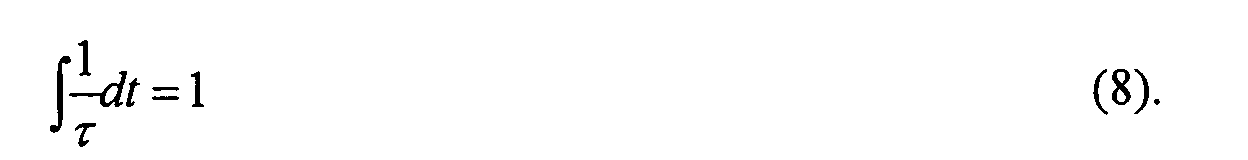
- the Livengood-Wu integral (8) is based on the concept that the end gas ignition delay ⁇ varies with the passage of time.
- the occurrence of end gas autoignition is judged at the time the integral of the inverse of the end gas ignition delay ⁇ with respect to the time t becomes equal to 1 (one).
- the end gas ignition delay ⁇ of the Livengood-Wu integral (8) may be expressed as a function of the temperature T and pressure p as in the equation (7). It is alternatively possible to store a preset ignition-delay map in ECU 11 and retrieve the end gas ignition delay ⁇ from the ignition-delay map with respect the temperature T and the pressure p.
- the heat transfer from the wall of combustion chamber 4 is given by the following equation (9): where A is the heat transfer area, h c is the heat transfer coefficient and T wall is the temperature of the combustion chamber wall.
- the model constants C 1 and C 2 are changed in accordance to the phase of cycles of compression, combustion and expansion.
- the Woschni's heat transfer model is originally designed to address average heat transfer throughout combustion chamber 4. To combine the Woschni's heat transfer model with the two-zone combustion model, it is thus necessary to allocate the amount of heat transferred from the wall of combustion chamber 4 to the burned and unburned zones in some way.
- the end gas is in a thermally insulated state during the heat release process. Based on such an assumption, the fourth term dQ u,wall of the equation (2) is taken as 0 (zero), and the fourth term dQ b,wall of the equation (1) is taken as the heat transfer amount of the equation (9).
- the progression of the end gas temperature T u and pressure p u over time are thus estimated by solving the equations (1) to (6) and (8) to (11) simultaneously for the crank angle ⁇ .
- the occurrence of end gas autoignition is judged by calculating the end gas ignition delay ⁇ from the estimated values, and then, integrating the inverse of the calculated end gas ignition delay ⁇ with respect to time t .
- the predicted value ⁇ knock of the autoignition timing is given as a crank angle at which the integral becomes equal to 1 (one) as in the equation (8).
- the predicted value X auto-ign of the autoignition heat release amount is given by substituting the predicted crank angle ⁇ knock into the equation (6) and then subtracting the thus-obtained current heat release amount from 1 (one).
- the knock intensity, the MBT ignition timing and the trace knock ignition timing are calculated from the predicted autoignition timing ⁇ knock and heat release amount X auto-ign in the same manner as in the first embodiment.
- the autoignition timing and heat release amount can be predicted accurately in view of the temporal characteristics of the end gas ignition delay ⁇ and the heat transfer from the wall of combustion chamber 4. This makes it possible to limit the knock intensity to the trace knock level more assuredly so as not to cause an undesired deterioration in engine thermal efficiency due to the overretardation of the ignition timing and thereby possible to maintain high engine thermal efficiency and durability.
- the third embodiment is similar to the first and second embodiments, except that the occurrence of end gas autoignition is predicted according to another autoignition model called "elementary reaction model".
- the elementary reaction model is based on the chemical kinetics in which an overall reaction is made up of a series of several tens to hundreds of elementary reactions so as to be conformable to actual physical phenomena (including molecule-to-molecule collision and reaction).
- the influence of not only the temperature and pressure but also the gas mixture composition and the fuel properties over the autoignition can be simulated by such an elementary reaction model.
- the elementary reaction model applied to the end gas in the unburned zone it becomes possible to predict the knock occurrence more accurately in response to the changes in valve timing, compression ratio, equivalence ratio, residual gas rate and octane number etc.
- the gas mixture of combustion chamber 4 contains a mass fraction y i of the chemical species i and that the mass fraction y i of the chemical species i varies during the reaction.
- the reaction rate ⁇ ⁇ i,u is expressed as a function of p , T u and y i,u .
- the reaction rate ⁇ ⁇ i,u can be easily computed by CHEMKIN (a computer program commonly known for calculation of known homogeneous reaction kinetics).
- the elementary reaction model to the burned zone so as to simulate not only engine knock, i.e., the end gas autoignition in the unburned zone but also the thermal dissociation and NO generation in the burned zone.
- the autoignition is regarded as a part of the continuous chemical reaction in the elementary reaction model. It is thus necessary to set a criterion for judging the occurrence of the autoignition. For example, the occurrence of the autoignition may judged when the end gas temperature T u becomes equal to or larger than a certain value.
- the predicted value ⁇ knock of the autoignition timing is given upon judging the occurrence of autoignition based on the set criterion. Then, the predicted value X auto-ign of the autoignition heat release amount is given by substituting the predicted crank angle ⁇ knock into the equation (6) and subtracting the thus-obtained current heat release amount from 1 (one).
- the knock intensity, the MBT ignition timing and the trace knock ignition timing are calculated from the predicted autoignition timing ⁇ knock and heat release amount X auto-ign in the same manner as in the first or second embodiment.
- FIG. 9 is a graph showing how the spark advance ⁇ ADV varies with the compression ratio ⁇ in the actual vehicle experiment and in the cycle simulation of the third embodiment. As shown in FIG. 9, the prediction results well agree with the experimental results qualitatively and quantitatively at each engine speed. The validity of the prediction in the third embodiment is thus clearly proved in FIG. 9.
- the autoignition timing and heat release amount can be predicted more accurately in response to the changes in valve timing, compression ratio, equivalence ratio, residual gas rate and octane number etc. because the influence of not only the temperature and pressure but also the gas mixture composition and the fuel properties over the end gas autoignition is reflected in the cycle simulation by the elementary reaction model.
- This makes it possible to limit the knock intensity to the trace knock level more assuredly so as not to cause an undesired deterioration in engine thermal efficiency due to the overretardation of the ignition timing and thereby possible to maintain high engine thermal efficiency and durability.
Landscapes
- Engineering & Computer Science (AREA)
- Chemical & Material Sciences (AREA)
- Combustion & Propulsion (AREA)
- Mechanical Engineering (AREA)
- General Engineering & Computer Science (AREA)
- Signal Processing (AREA)
- Combined Controls Of Internal Combustion Engines (AREA)
- Electrical Control Of Ignition Timing (AREA)
- Output Control And Ontrol Of Special Type Engine (AREA)
Abstract
Description
Further,
This makes it possible to limit the knock intensity to the trace knock level more assuredly so as not to cause an undesired deterioration in engine thermal efficiency due to the overretardation of the ignition timing and thereby possible to maintain high engine thermal efficiency and durability.


Claims (13)
- A combustion control system for a spark ignition internal combustion engine, the system being configured to:detect engine operating conditions;predict, based on the detected engine operating conditions, autoignition timing of an end gas and an amount of heat released due to autoignition of the end gas; andcontrol combustion to establish such a relationship between the autoignition timing and the amount of heat released due to the autoignition as to give a knock intensity not higher than a specified intensity limit.
- A combustion control system for a spark-ignition internal combustion engine, the system being configured to:detect engine operating conditions;predict, based on the detected engine operating conditions, an autoignition timing of an end gas and an amount of heat released due to autoignition of the end gas;calculate a knock intensity from the autoignition timing and the amount of heat released due to the autoignition; andcontrol combustion in the engine in such a manner that the knock intensity is lower than or equal to a specified intensity limit.
- A combustion control system according to Claim 1 or 2, wherein the knock intensity is calculated such that the knock intensity increases as the amount of heat released due to the autoignition is increased and as the autoignition timing is advanced.
- A combustion control system according to Claim 3, wherein the knock intensity is calculated such that the knock intensity increases with engine speed.
- A combustion control system according to any one of Claims 1 to 4,
wherein the specified intensity limit corresponds to a trace knock level. - A combustion control system according to any one of Claims 1 to 5, wherein the combustion is controlled by adjusting ignition timing.
- A combustion control system according to any one of Claims 1 to 6, wherein the autoignition timing and the amount of heat released due to the autoignition are predicted by estimating an ignition delay of the end gas.
- A combustion control system according to any one of Claims 1 to 6, wherein the occurrence of the autoignition is predicted by integrating the inverse of an ignition delay of the end gas to estimate the autoignition timing and the amount of heat released due to the autoignition.
- A combustion control system according to any one of Claims 1 to 6, wherein the occurrence of the autoignition is predicted by an elementary reaction model to estimate the autoignition timing and the amount of heat released due to the autoignition.
- A combustion control method for a spark-ignition internal combustion engine, comprising:detecting engine operating conditions;predicting, based on the detected engine operating conditions, autoignition timing of an end gas and an amount of heat released due to autoignition of the end gas; andcontrolling combustion to establish such a relationship between the autoignition timing and the amount of heat released due to the autoignition as to give a knock intensity not higher than a specified intensity limit.
- A combustion control method for a spark-ignition internal combustion engine, comprising:detecting engine operating conditions;predicting, based on the detected engine operating conditions, autoignition timing of an end gas and an amount of heat released due to autoignition of the end gas;calculating a knock intensity from the autoignition timing and the amount of heat released due to the autoignition; andcontrolling combustion in the engine in such a manner that the knock intensity is lower than or equal to a specified intensity limit.
- A combustion control method according to Claim 10 or 11, further comprising:wherein said controlling includes setting spark ignition timing to either one of the MBT ignition timing and the trace knock ignition timing located on a retard side.computing an engine torque while calculating the knock intensity; anddetermining trace knock ignition timing and MBT ignition timing based on the knock intensity and the engine torque,
- A combustion control method according to any one of Claims 10 to 12, wherein the knock intensity is calculated such that the knock intensity increases as the amount of heat released due to the autoignition is increased, as the autoignition timing is advanced and as engine speed is increased.
Applications Claiming Priority (2)
| Application Number | Priority Date | Filing Date | Title |
|---|---|---|---|
| JP2003126869 | 2003-05-02 | ||
| JP2003126869A JP4036138B2 (en) | 2003-05-02 | 2003-05-02 | Combustion control device for spark ignition internal combustion engine |
Publications (2)
| Publication Number | Publication Date |
|---|---|
| EP1473452A2 true EP1473452A2 (en) | 2004-11-03 |
| EP1473452A3 EP1473452A3 (en) | 2005-06-08 |
Family
ID=32985606
Family Applications (1)
| Application Number | Title | Priority Date | Filing Date |
|---|---|---|---|
| EP04010105A Withdrawn EP1473452A3 (en) | 2003-05-02 | 2004-04-28 | Combustion control system and method for spark-ignition internal combustion engine |
Country Status (3)
| Country | Link |
|---|---|
| US (1) | US6999866B2 (en) |
| EP (1) | EP1473452A3 (en) |
| JP (1) | JP4036138B2 (en) |
Cited By (9)
| Publication number | Priority date | Publication date | Assignee | Title |
|---|---|---|---|---|
| EP1956231A3 (en) * | 2007-02-08 | 2013-10-30 | IAV GmbH Ingenieurgesellschaft Auto und Verkehr | Knock control method |
| WO2014164698A2 (en) | 2013-03-11 | 2014-10-09 | Wayne State University | Predictive correction in internal combustion engines |
| EP2706213A4 (en) * | 2011-05-02 | 2015-12-16 | Toyota Motor Co Ltd | INTERNAL COMBUSTION ENGINE WITH SPARK IGNITION |
| WO2017093638A1 (en) * | 2015-12-04 | 2017-06-08 | Renault S.A.S. | Method of estimating the mass enclosed in the combustion chamber of a cylinder of a motor vehicle internal combustion engine |
| EP2312142A3 (en) * | 2009-10-06 | 2017-08-02 | Cosmo Oil Co., Ltd. | Combustion timing prediction method and apparatus for compression ignition internal combustion engine |
| AT517858A3 (en) * | 2015-10-31 | 2017-10-15 | Man Diesel & Turbo Se | Configuration tool for a gas engine or a dual-fuel engine and method for parameterizing the same |
| CN110265090A (en) * | 2019-01-04 | 2019-09-20 | 吉林大学 | A method for evaluating gasoline anti-knock performance for vehicle engines |
| EP3680477A4 (en) * | 2017-09-06 | 2021-06-23 | IHI Corporation | ENGINE CONTROL SYSTEM |
| US11078860B2 (en) | 2013-03-11 | 2021-08-03 | Wayne State University | Predictive correction in internal combustion engines |
Families Citing this family (36)
| Publication number | Priority date | Publication date | Assignee | Title |
|---|---|---|---|---|
| DE10327691A1 (en) * | 2003-06-20 | 2005-01-05 | Robert Bosch Gmbh | Method for monitoring the exhaust gas recirculation of an internal combustion engine |
| JP4075818B2 (en) * | 2004-02-20 | 2008-04-16 | 日産自動車株式会社 | Ignition timing control device for internal combustion engine |
| JP2006177241A (en) * | 2004-12-22 | 2006-07-06 | Nissan Motor Co Ltd | Control device for internal combustion engine |
| US6997149B1 (en) * | 2005-03-30 | 2006-02-14 | Gm Global Technology Operations, Inc. | Spark timing control and method |
| JP4380604B2 (en) * | 2005-07-29 | 2009-12-09 | トヨタ自動車株式会社 | Control device for internal combustion engine |
| JP2007040219A (en) * | 2005-08-04 | 2007-02-15 | Toyota Motor Corp | Control device for internal combustion engine |
| US7213572B2 (en) * | 2005-09-21 | 2007-05-08 | Ford Global Technologies, Llc | System and method for engine operation with spark assisted compression ignition |
| US7398758B2 (en) * | 2005-10-25 | 2008-07-15 | Gm Global Technology Operations, Inc. | Combustion control method for a direct-injection controlled auto-ignition combustion engine |
| JP2007126997A (en) * | 2005-11-01 | 2007-05-24 | Toyota Motor Corp | In-cylinder heat generation simulation method and simulation apparatus |
| JP4581993B2 (en) * | 2005-12-26 | 2010-11-17 | トヨタ自動車株式会社 | Combustion abnormality detection device for internal combustion engine |
| JP4677897B2 (en) * | 2005-12-28 | 2011-04-27 | トヨタ自動車株式会社 | Ignition timing control device for internal combustion engine |
| JP2007248119A (en) * | 2006-03-14 | 2007-09-27 | Toyota Motor Corp | Method for determining Wiebe function parameter and heat generation rate estimating apparatus for internal combustion engine |
| JP2007285280A (en) * | 2006-04-20 | 2007-11-01 | Toyota Motor Corp | Control device for internal combustion engine |
| JP4687627B2 (en) * | 2006-10-06 | 2011-05-25 | トヨタ自動車株式会社 | Apparatus and method for estimating knock generation ignition timing of internal combustion engine |
| JP4710788B2 (en) * | 2006-10-11 | 2011-06-29 | トヨタ自動車株式会社 | Control device for internal combustion engine |
| US7469181B2 (en) * | 2007-01-29 | 2008-12-23 | Caterpillar Inc. | High load operation in a homogeneous charge compression ignition engine |
| JP4803099B2 (en) * | 2007-04-26 | 2011-10-26 | トヨタ自動車株式会社 | Torque estimation device for variable compression ratio engine |
| US8631782B2 (en) * | 2008-08-22 | 2014-01-21 | GM Global Technology Operations LLC | Active compression ratio modulation through intake valve phasing and knock sensor feedback |
| JP5526408B2 (en) * | 2010-01-19 | 2014-06-18 | 国立大学法人東北大学 | Fuel property determination method and fuel property determination device |
| JP5453221B2 (en) | 2010-11-18 | 2014-03-26 | 国立大学法人東北大学 | Combustion experiment equipment |
| US9020791B2 (en) | 2011-12-06 | 2015-04-28 | Toyota Motor Engineering & Maunfacturing North America, Inc. | Process for designing and manufacturing an ignition system for an internal combustion engine |
| US9279406B2 (en) | 2012-06-22 | 2016-03-08 | Illinois Tool Works, Inc. | System and method for analyzing carbon build up in an engine |
| WO2014182931A1 (en) | 2013-05-08 | 2014-11-13 | Robert Bosch Gmbh | Method of estimating duration of auto-ignition phase in a spark-assisted compression ignition operation |
| JP2015117652A (en) * | 2013-12-19 | 2015-06-25 | 日立オートモティブシステムズ株式会社 | Control device of internal combustion engine |
| JP6336818B2 (en) * | 2014-05-13 | 2018-06-06 | 株式会社Soken | Fuel supply control system for internal combustion engine |
| JP6167999B2 (en) * | 2014-06-16 | 2017-07-26 | スズキ株式会社 | Combustion timing estimation apparatus and combustion timing estimation method for premixed compression self-ignition internal combustion engine |
| US10570835B2 (en) * | 2014-09-04 | 2020-02-25 | Transportation Ip Holdings, Llc | Substitution rate control system for an engine and an associated method thereof |
| JP6500816B2 (en) * | 2016-03-14 | 2019-04-17 | トヨタ自動車株式会社 | Control device for internal combustion engine |
| US20180045131A1 (en) * | 2016-08-10 | 2018-02-15 | Brian Rockwell | Combustion phasing control techniques using a physics-based combustion model |
| JP2018080626A (en) * | 2016-11-16 | 2018-05-24 | 三菱自動車工業株式会社 | Engine control device |
| JP6168231B2 (en) * | 2016-12-16 | 2017-07-26 | スズキ株式会社 | Control device for premixed compression self-ignition internal combustion engine |
| US20200208587A1 (en) * | 2017-10-27 | 2020-07-02 | Mitsubishi Heavy Industries Engine & Turbocharger, Ltd. | Knocking detection method and knocking detection device |
| JP6848888B2 (en) * | 2018-01-22 | 2021-03-24 | マツダ株式会社 | Engine capable of suppressing strong knock |
| JP7251451B2 (en) * | 2019-11-15 | 2023-04-04 | マツダ株式会社 | engine controller |
| CN111207009B (en) * | 2019-12-26 | 2023-01-13 | 中国空气动力研究与发展中心 | Method for initiating oblique detonation wave in supersonic velocity airflow by using external instantaneous energy source |
| CN112562793B (en) * | 2020-12-10 | 2023-01-03 | 北京理工大学 | Two-step reaction model calculation method for fuel detonation combustion |
Family Cites Families (6)
| Publication number | Priority date | Publication date | Assignee | Title |
|---|---|---|---|---|
| JPS6296778A (en) | 1985-10-22 | 1987-05-06 | Nissan Motor Co Ltd | Ignition timing control device |
| US4846129A (en) | 1988-02-09 | 1989-07-11 | Chrysler Motors Corporation | Ignition system improvements for internal combustion engines |
| US5206809A (en) * | 1989-09-04 | 1993-04-27 | Nissan Motor Company, Limited | Heat measuring system for detecting knock in internal combustion engine |
| US5386722A (en) * | 1993-03-24 | 1995-02-07 | Ford Motor Company | Method and apparatus for statistically determining knock borderline and evaluating knock intensity in an internal combustion engine |
| JPH07332149A (en) | 1994-06-07 | 1995-12-22 | Toyota Central Res & Dev Lab Inc | Combustion control device for internal combustion engine |
| US6227151B1 (en) | 1997-08-01 | 2001-05-08 | Ford Global Technologies, Inc. | Gasoline internal combustion engine |
-
2003
- 2003-05-02 JP JP2003126869A patent/JP4036138B2/en not_active Expired - Fee Related
-
2004
- 2004-04-21 US US10/828,458 patent/US6999866B2/en not_active Expired - Fee Related
- 2004-04-28 EP EP04010105A patent/EP1473452A3/en not_active Withdrawn
Cited By (15)
| Publication number | Priority date | Publication date | Assignee | Title |
|---|---|---|---|---|
| EP1956231A3 (en) * | 2007-02-08 | 2013-10-30 | IAV GmbH Ingenieurgesellschaft Auto und Verkehr | Knock control method |
| EP2312142A3 (en) * | 2009-10-06 | 2017-08-02 | Cosmo Oil Co., Ltd. | Combustion timing prediction method and apparatus for compression ignition internal combustion engine |
| EP2706213A4 (en) * | 2011-05-02 | 2015-12-16 | Toyota Motor Co Ltd | INTERNAL COMBUSTION ENGINE WITH SPARK IGNITION |
| US9482163B2 (en) | 2011-05-02 | 2016-11-01 | Toyota Jidosha Kabushiki Kaisha | Spark ignition type internal combustion engine |
| US9951741B2 (en) | 2013-03-11 | 2018-04-24 | Wayne State University | Predictive correction in internal combustion engines |
| EP2971714A4 (en) * | 2013-03-11 | 2017-04-12 | Wayne State University | Predictive correction in internal combustion engines |
| WO2014164698A2 (en) | 2013-03-11 | 2014-10-09 | Wayne State University | Predictive correction in internal combustion engines |
| US11078860B2 (en) | 2013-03-11 | 2021-08-03 | Wayne State University | Predictive correction in internal combustion engines |
| AT517858A3 (en) * | 2015-10-31 | 2017-10-15 | Man Diesel & Turbo Se | Configuration tool for a gas engine or a dual-fuel engine and method for parameterizing the same |
| US10260982B2 (en) | 2015-10-31 | 2019-04-16 | Man Energy Solutions Se | Project planning tool for a gas engine or a dual-fuel engine and method for parameterisation of the same |
| WO2017093638A1 (en) * | 2015-12-04 | 2017-06-08 | Renault S.A.S. | Method of estimating the mass enclosed in the combustion chamber of a cylinder of a motor vehicle internal combustion engine |
| FR3044717A1 (en) * | 2015-12-04 | 2017-06-09 | Renault Sas | METHOD OF ESTIMATING MASS EMERGED IN THE COMBUSTION CHAMBER OF A CYLINDER OF A MOTOR VEHICLE INTERNAL COMBUSTION ENGINE |
| EP3680477A4 (en) * | 2017-09-06 | 2021-06-23 | IHI Corporation | ENGINE CONTROL SYSTEM |
| US11085380B2 (en) | 2017-09-06 | 2021-08-10 | Ihi Corporation | Engine control system |
| CN110265090A (en) * | 2019-01-04 | 2019-09-20 | 吉林大学 | A method for evaluating gasoline anti-knock performance for vehicle engines |
Also Published As
| Publication number | Publication date |
|---|---|
| US20040220720A1 (en) | 2004-11-04 |
| EP1473452A3 (en) | 2005-06-08 |
| JP4036138B2 (en) | 2008-01-23 |
| US6999866B2 (en) | 2006-02-14 |
| JP2004332584A (en) | 2004-11-25 |
Similar Documents
| Publication | Publication Date | Title |
|---|---|---|
| US6999866B2 (en) | Combustion control system and method for spark-ignition internal combustion engine | |
| US7212909B2 (en) | Ignition timing control for internal combustion engine | |
| US6560526B1 (en) | Onboard misfire, partial-burn detection and spark-retard control using cylinder pressure sensing | |
| EP1571333B1 (en) | Ignition timing control for internal combustion engine | |
| JP3975936B2 (en) | Knocking index value calculation device | |
| EP1835153A2 (en) | Controller for compression ignition engine | |
| US7222606B2 (en) | Ignition timing control for internal combustion engine | |
| Rothe et al. | Knock behavior of SI-engines: thermodynamic analysis of knock onset locations and knock intensities | |
| Chang et al. | Analysis of load and speed transitions in an HCCI engine using 1-D cycle simulation and thermal networks | |
| US7624718B2 (en) | Engine control system, vehicle having the same, method for calculating combustion center of gravity, and method for controlling engine | |
| US11391226B2 (en) | Internal combustion engine control device and internal combustion engine control method | |
| JP4158747B2 (en) | Ignition timing control device for internal combustion engine | |
| Karagiorgis et al. | Residual gas fraction measurement and estimation on a homogeneous charge compression ignition engine utilizing the negative valve overlap strategy | |
| Karagiorgis et al. | Dynamic modeling of combustion and gas exchange processes for controlled auto-ignition engines | |
| JP5087569B2 (en) | Control device for compression self-ignition internal combustion engine | |
| JP4158720B2 (en) | Ignition timing control device for internal combustion engine | |
| Panousakis et al. | Analysis of SI combustion diagnostics methods using ion-current sensing techniques | |
| JP4135655B2 (en) | Ignition timing control device for internal combustion engine | |
| JP4075819B2 (en) | Ignition timing control device for internal combustion engine | |
| JP2006144642A (en) | Control device and control method for internal combustion engine | |
| JP4182897B2 (en) | Ignition timing control device for internal combustion engine | |
| WO2026028583A1 (en) | Control device of internal combustion engine | |
| CN121630618A (en) | Systems and methods for adaptively managing engine knock | |
| Ogura et al. | Primary reference fuel behavior in a HCCI engine near the low-load limit | |
| Joyce et al. | Linear regression and its use in predicting the link between ionization current and the pressure signal in a hybrid mode engine |
Legal Events
| Date | Code | Title | Description |
|---|---|---|---|
| PUAI | Public reference made under article 153(3) epc to a published international application that has entered the european phase |
Free format text: ORIGINAL CODE: 0009012 |
|
| 17P | Request for examination filed |
Effective date: 20040428 |
|
| AK | Designated contracting states |
Kind code of ref document: A2 Designated state(s): AT BE BG CH CY CZ DE DK EE ES FI FR GB GR HU IE IT LI LU MC NL PL PT RO SE SI SK TR |
|
| AX | Request for extension of the european patent |
Extension state: AL HR LT LV MK |
|
| PUAL | Search report despatched |
Free format text: ORIGINAL CODE: 0009013 |
|
| AK | Designated contracting states |
Kind code of ref document: A3 Designated state(s): AT BE BG CH CY CZ DE DK EE ES FI FR GB GR HU IE IT LI LU MC NL PL PT RO SE SI SK TR |
|
| AX | Request for extension of the european patent |
Extension state: AL HR LT LV MK |
|
| AKX | Designation fees paid |
Designated state(s): DE FR GB |
|
| STAA | Information on the status of an ep patent application or granted ep patent |
Free format text: STATUS: THE APPLICATION IS DEEMED TO BE WITHDRAWN |
|
| 18D | Application deemed to be withdrawn |
Effective date: 20161101 |