EP1473229A1 - Chemical bag feeder - Google Patents
Chemical bag feeder Download PDFInfo
- Publication number
- EP1473229A1 EP1473229A1 EP03701054A EP03701054A EP1473229A1 EP 1473229 A1 EP1473229 A1 EP 1473229A1 EP 03701054 A EP03701054 A EP 03701054A EP 03701054 A EP03701054 A EP 03701054A EP 1473229 A1 EP1473229 A1 EP 1473229A1
- Authority
- EP
- European Patent Office
- Prior art keywords
- medicine envelope
- medicine
- holding member
- envelope
- support member
- Prior art date
- Legal status (The legal status is an assumption and is not a legal conclusion. Google has not performed a legal analysis and makes no representation as to the accuracy of the status listed.)
- Granted
Links
Images







Classifications
-
- B—PERFORMING OPERATIONS; TRANSPORTING
- B65—CONVEYING; PACKING; STORING; HANDLING THIN OR FILAMENTARY MATERIAL
- B65B—MACHINES, APPARATUS OR DEVICES FOR, OR METHODS OF, PACKAGING ARTICLES OR MATERIALS; UNPACKING
- B65B5/00—Packaging individual articles in containers or receptacles, e.g. bags, sacks, boxes, cartons, cans, jars
- B65B5/08—Packaging groups of articles, the articles being individually gripped or guided for transfer to the containers or receptacles
-
- B—PERFORMING OPERATIONS; TRANSPORTING
- B65—CONVEYING; PACKING; STORING; HANDLING THIN OR FILAMENTARY MATERIAL
- B65B—MACHINES, APPARATUS OR DEVICES FOR, OR METHODS OF, PACKAGING ARTICLES OR MATERIALS; UNPACKING
- B65B7/00—Closing containers or receptacles after filling
- B65B7/02—Closing containers or receptacles deformed by, or taking-up shape, of, contents, e.g. bags, sacks
- B65B7/06—Closing containers or receptacles deformed by, or taking-up shape, of, contents, e.g. bags, sacks by collapsing mouth portion, e.g. to form a single flap
- B65B7/08—Closing containers or receptacles deformed by, or taking-up shape, of, contents, e.g. bags, sacks by collapsing mouth portion, e.g. to form a single flap and folding
-
- B—PERFORMING OPERATIONS; TRANSPORTING
- B65—CONVEYING; PACKING; STORING; HANDLING THIN OR FILAMENTARY MATERIAL
- B65B—MACHINES, APPARATUS OR DEVICES FOR, OR METHODS OF, PACKAGING ARTICLES OR MATERIALS; UNPACKING
- B65B35/00—Supplying, feeding, arranging or orientating articles to be packaged
- B65B35/10—Feeding, e.g. conveying, single articles
- B65B35/16—Feeding, e.g. conveying, single articles by grippers
-
- B—PERFORMING OPERATIONS; TRANSPORTING
- B65—CONVEYING; PACKING; STORING; HANDLING THIN OR FILAMENTARY MATERIAL
- B65B—MACHINES, APPARATUS OR DEVICES FOR, OR METHODS OF, PACKAGING ARTICLES OR MATERIALS; UNPACKING
- B65B5/00—Packaging individual articles in containers or receptacles, e.g. bags, sacks, boxes, cartons, cans, jars
- B65B5/10—Filling containers or receptacles progressively or in stages by introducing successive articles, or layers of articles
- B65B5/105—Filling containers or receptacles progressively or in stages by introducing successive articles, or layers of articles by grippers
Definitions
- the present invention relates to a medicine envelope feeder.
- each storage chamber in the bucket needs to be formed such that the medicine envelopes could be accommodated upright and easily in each storage chamber so as to prevent the injection stored in the medicine envelopes from being leaked.
- a medicine envelope feeder comprising:
- the medicine envelope can be positioned between the guide member and the guide part of the holding member, and the tolerance for bending of the medicine envelope can be bent and pressed by the pressing part.
- the support member is dropped off due to the difference in a coefficient of friction, by which the medicine envelope is fed while being held between the guide part and the pressing part.
- a part of the support member held between the guide part and the pressing part of the holding member should preferably be composed of a rotating piece rotatable about one end part.
- the rotating piece gradually rotates as the holding member is raised, so that the friction force of the support member exerted on the medicine envelope is gradually reduced. This enables the holding member to hold and feed the medicine envelopes smoothly.
- the support member is provided in a rotatable manner around a lower end part and comprises medicine envelope detection means for detecting that the medicine envelope is fed, driving means for rotary-driving the support member by the medicine envelope detection mean detecting the medicine envelope, and rotating position detecting means for detecting that the support member is rotated in a state that the medicine envelope is held between the support member and the guide part of the holding member, so that the medicine envelopes storing injection can be automatically and smoothly moved to a feeding operation by the holding member.
- the holding member should preferably be capable of moving in horizontal direction, and comprise a rotatable contact piece which is brought into contact with one surface of the medicine envelope as the holding member moves in horizontal direction when the held medicine envelope is fed to the bucket, so that a folded part of the medicine envelope can be positioned between the medicine envelope which have already been fed into the bucket and the holding member, thereby ensuring prevention of injection from leaking.
- the holding member should preferably comprise an inclined face which is provided on a lower end part of the guide part and is gradually inclined from the pressing part toward a lower side, so that by moving the pressing part along the inclined face of the guide part, the held medicine envelope can be inclined with a folded side facing down, allowing the medicine envelopes to be securely positioned sideways and housed horizontally in the bucket.
- the holding member should preferably further comprise an elastic pressing piece for pressing an upper folded side of the medicine envelope after retaining the medicine envelope on a bottom surface of the bucket by the contact piece, which makes it possible to ensure prevention of the folded part of the medicine envelope in the bucket from opening.
- a medicine envelope feeder comprising:
- a rotating angle of the nip arms in the holding member should preferably be changeable according to conditions of the medicine envelope, which implements a smooth operation without opening the opening part when the medicine envelopes are fed and placed.
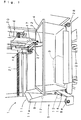
- Fig. 1 shows a medicine envelope feeder according to the first embodiment.
- the medicine envelope feeder 1 which is for feeding medicine envelopes 3 storing injection 2 (see FIG. 3 (a)) such as injection in ampules to a bucket 4 for automatic transportation, is mainly composed of a support member 5 and a holding member 6.
- the medicine envelope 3 is of bag type formed by attaching a resin film 8 on three sides of a paper sheet 7, that are both lateral sides and a lower edge side, and the film 8 contains information on the injection 2 to be stored (e.g., drug name, quantity, etc.) printed thereon.
- the support member 5 is composed of a support plate 9 which 'is made of stainless steel or the like with the both lateral sides being folded at right angles, and is provided in a rotatable manner so as to rotate about a spindle 9a on the lower end by driving of an unshown rotating motor.
- the upper end part of the support plate 9 is composed of a rotating piece 11 rotatable about a spindle 11a.
- the height of the support plate 9 is set at a value allowing a folded part of the medicine envelope 3 to protrude from the upper edge in the state of supporting the medicine envelope 3.
- a medicine envelope detection sensor 12 is provided on the central part of the support plate 9 so that the presence or absence of the medicine envelope 3 to be fed can be detected.
- a detection disk 13 is provided on the spindle 9a, so that a rotating position of the support plate 9 can be detected by the detection disk 13 being detected by a rotating position detection sensor 14.
- the support member 5 can rotate between a reception position (chain double-dashed line in FIG. 3 (a)) of the medicine envelope 3 that is inclined at a slant angle and a delivery position (solid line in FIG. 1 and FIG. 3(a)) rotated in vertical direction.
- the holding member 6 is composed of a guide plate 15 and a pressing arm 16 attached to the guide plate 15 in a rotatable and vertically movable manner.
- the guide plate 15, which is placed on a holding plate 17, is vertically moved along a slide rail extending in vertical direction by driving of a Y-axis servomotor 18.
- the holding plate 17 is moved, as shown in Fig. 1, in horizontal direction via a rod screw 21 by driving of an X-axis servomotor 20.
- the holding member 6 can freely move in Y-axis direction (vertical direction) and X-axis direction (horizontal direction), i.e., to respective positions including a standby position on the upper right end, a medicine envelope reception position on the lower left side and a medicine envelope feeding position to the bucket 4 on the light side in FIG. 1.
- guide blocks 24 are laid side by side in vertical direction on one face of the guide plate 15 at a specified interval.
- a contact piece 22 is provided rotatably about a spindle 22a.
- the contact piece 22 has a large notch on the central part so that only both side parts can come into contact with the medicine envelope 3.
- the pressing arm 16 is composed of a rod-like guide part 26 provided rotatably about a spindle 26a.
- a guide piece 25 is vertically moved by driving of an unshown motor while being guided by the guide blocks 24.
- a pressing part 27 extending in across-the-width direction is provided on the top end of the guide part 26.
- the pressing part 27 is structured such that a material having a large coefficient of fraction (at least larger than that of the support plate 9) against the medicine envelope 3 made of silicon rubber or the like is formed into a cylinder shape, and is provided rotatably about a spindle 27a.
- the pressing arm 16 is biased by an unshown spring or the like in such a manner that the pressing part 27 comes into pressure contact with the side of the guide plate 15.
- the bucket 4 can be conveyed by a conveyer device 28 as shown in FIG. 1. Further, the conveyer device 28 itself can move along a slide rail 29.
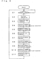
- step S1 Once a power supply is turned on (step S1), there is executed an initial operation consisting of designating its home position and then sitting in a specified position (step S2) on standby. More specifically, the support member 5 is positioned at a reception position of the medicine envelope 3 (chain double-dashed line in FIG. 3(a)), the holding member 6 is positioned at a home position on the upper right end in FIG. 1, and the pressing arm 16 of the holding member 6 is positioned in a raising position. In this state, the medicine envelope 3 storing the injection 2 is fed by an unshown bagging device to the support member 5 that is positioned at the reception position (step S3).
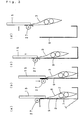
- the holding member 6 is moved to the medicine envelope reception position (step S4) while the support member 5 is rotated from the reception position to the delivery position (step S5). Consequently, the medicine envelope 3 held by the support member 5 is, as shown in FIG. 3(a), held between the support plate 9 of the support member 5 and the guide plate 15 of the holding member 6. At this point, the lower side of the medicine envelope 3 is guided by the support plate 9 excluding a tolerance for bending starting from the upper end opening part, and the range exceeding the tolerance for bending starting from the upper end opening part is guided by the guide plate 15.
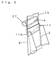
- the pressing arm 16 After lapse of specified standby time (herein 1 sec.), the pressing arm 16 is lowered so that as shown in FIG. 3(b), the tolerance for bending of the medicine envelope 3 is folded along the support plate 9 by the pressing part 27 (step S6). Once the pressing part 27 moves to a lowermost point, the holding member 6 is raised (step S7). The friction force exerted to the medicine envelope 3 is sufficiently larger in the pressing part 27 than in the support member 5. Consequently, as shown by the double-dashed line in FIG. 3 (a) or in detail in FIG. 5, as the holding member 6 is raised, the support member 5 gradually slips away from the medicine envelope 3 and the rotating piece 11 rotates about the spindle 11a.
- step S8 the holding member 6 is moved in horizontal direction so as to be positioned above the bucket 4 (step S8), and the medicine envelope 3 is lowered till its lower end part reaches a discharge' position located in the vicinity of the bottom surface of the bucket 4 as shown in FIG. 4(a) (step S9).
- step S10 the holding member 6 is lowered while being gradually moved in horizontal direction toward the support member 5 side (step S10).
- the contact piece 22 comes into contact with the medicine envelope 3. Consequently, the medicine envelope 3 is gradually inclined with the folded side facing down.
- the pressing arm 16 is raised and the held state of the medicine envelope 3 by the pressing part 27 is released (step S11). Since the medicine envelope 3 is inclined as described before, the folded side is retained on the bottom surface of the bucket 4 (or the medicine envelope 3 accommodated in advance) as shown in FIG. 4(c), making it difficult to open the medicine envelope 3.
- the medicine envelope 3 is fed to the bucket 4 with the opening part being folded.
- the movement position of the holding member 6 is gradually changed in conformity to a preset position information. This enables the medicine envelopes 3 to be smoothly accommodated in sequence in the bucket 4 while the folded side being held without generating unnecessary spaces.
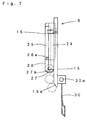
- the holding member 6 is structured as shown in FIG. 2 in the aforementioned embodiment, it is also acceptable to form an inclined face 15a on a lower end part of the guide plate 15 and allow the pressing part 27 to move to the inclined face 15a as shown in FIG. 7. This makes it possible to compel the medicine envelope 3 to be inclined,' thereby allowing the folded part to securely face down when the medicine envelope 3 is fed to the bucket 4.
- the contact piece 22 may be composed of a plate-like article 30 provided rotatably about a spindle 30a.
- a sensor (unshown) for detecting a rotating position of the contact piece 22 (30). In this constitution, in the case where, for example, quantity of the injection 2 stored in the medicine envelope 3 is large, it becomes possible to detect by the sensor that the rotating position of the contact piece 22 (30) is changed from a normal position and to correct the movement position of the holding member 6.
- the upper part of the medicine envelope 3 is simply folded in the aforementioned embodiment, it is also acceptable to partially apply adhesives or the like to the medicine envelope 3, or to thermally deposit the medicine envelope 3 by heating a part of the guide plate 15 so as to maintain the folded state.
- the medicine envelopes 3 are fed in the bucket 4 starting from the left side.
- the chemicals bag 3 are accommodated therein starting from the right side, the folded part of the already accommodated medicine envelope 3 can be pressed in sequence by the part of a next medicine envelope 3 in which the injection 2 is housed, which further stabilizes the accommodation state and makes it possible to secure prevention of the injection 2 from leaking.
- the medicine envelope 3 is accommodated in this manner, the folded side will not protrude upward, allowing smooth accommodation of the medicine envelopes 3 on the second level.
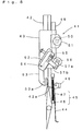
- FIG. 8 shows a holding member 41 in a medicine envelope feeder according to the second embodiment.
- a holding guide 43 is provided in a vertically movable manner on a guide plate 42 which moves in Y-axis and X-axis direction.
- a contact piece 44 and an elastic pressing piece 45 are provided on the lower back face of the guide plate 42.
- the contact piece 44 is a plate-like article provided rotatably about a spindle 44a, whose rotating position is detected by a sensor 46 like the contact piece shown in FIG. 7.
- the elastic pressing piece 45 which is formed by providing a resin protrusion 48 on the top end of a coil spring 47, has a length almost half of the contact piece 44 and protrudes downward from the guide plate 42.
- the head of the protrusion 48 is formed into a semispherical shape so that the medicine envelope 3 is not damaged. Moreover, on the lower end of the guide plate 42, there is formed an inclined face 42a that is inclined to the back surface side toward lower side.
- a holding guide 43 is vertically moved by rotary-driving a pinion 50 that is engaged with a rack 49 by a motor 51.
- the holding guide 43 is equipped with an arm holding part 52 and a pressing arm 53 which are provided rotatably about a spindle 54.
- the pressing arm 53 has an almost cylindrical pressure part 53a made of a silicon rubber which is rotatably provided on the top end, and is biased counterclockwise in the drawing against the arm holding part 52 by a biasing force of a spring 55. Further, the arm holding part 52 and the pressing arm 53 are rotated by driving of a motor 56 via links 57a, 57b.
- the pressing part 53a of the pressing arm 53 should preferably be formed not only into a cylindrical shape but to have a circular groove over the entire circumference at specified intervals in axis direction. According to this constitution, a pressure contact force generated when the medicine envelope is held by the pressing part 53a is concentrated into a part other than the circular groove, while air in the medicine envelope can be released outside, which achieves a stabilized state.
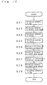
- step S21 the holding member 41 holding the medicine envelope is raised (step S21) and horizontally moved to the right side (step S22) before being lowered to a position shown in FIG. 9 (step S23).
- step S24 the holding guide 43 is lowered from the guide plate 42 (step S24), and the pressing part 53a is moved to an inclined face 42a.
- the motor 56 is driven in normal rotation so as to rotate the arm holding part 52 and the pressing arm 53 about a spindle 54 via the links 57a, 57b (step S25) , and at the same time, the holding member 41 is horizontally moved to the left side while being lowered (step S26).
- the pressing part 53a moves to the back face side beyond the inclined face 42a, ensuring the folded state of the medicine envelope 3.
- the medicine envelope 3 itself is inclined so that the folded side is positioned on the bottom surface side as shown in FIG. 10.
- the motor 56 is driven in reverse rotation so as to rotate the arm holding part 52 and the pressing arm 53 clockwise about the spindle 54 via the links 57a, 57b (step S27).
- the holding member 41 is horizontally moved to the left side while being lowered (step S28).
- the medicine envelope 3 is held in between the contact piece 44 and the bottom surface of the bucket 4, and the held state by the pressing arm 53 is released in the state that displacement of the medicine envelope 3 is prevented.
- the holding member 41 moves, the contact position of the protrusion 48 of the elastic pressing piece 45 on the medicine envelope 3 shifts to the folded position side.
- the medicine envelope 3 is positioned sideways while the elastic pressing piece 45 securely prevents the folded part from opening.
- the holding member 41 is raised (step S29) to be ready for feeding of a next medicine envelope 3.
- the folded part of the medicine envelope 3 fed into the bucket 4 in this way is reliably positioned facing down, which prevents the stored injection 2 from leaking during conveyance of the bucket 4 and the like.
- Fig. 13 shows a holding member 61 of a medicine envelope feeder according to the third embodiment.
- the holding member 61 is provided with a guide plate 62 that moves in X-axis and Y-axis direction.
- the guide plate 62 is composed of a first support plate 63 and a second support plate 64 which are laid side by side at a specified interval.
- the first support plate 63 is equipped with a motor 65 capable of driving in both normal and reverse rotations, and a drive gear 66 is fixed to its rotating shaft.
- An shaft member 67 is rotatably supported by the both support plates 63, 64.
- a driven gear 68 that engages with the drive gear 66 is integrated with one end part of the shaft member 67. Moreover, a detection disk 70 having a detection part 69 made of a magnet disposed on three positions on the circumference is fixed to the other end part of the shaft member 67.
- the second support plate 64 is provided with a sensor 71 for detecting the detection part 69.
- a drive disk 72 is fixed on the central part of the shaft member 67.
- a guide shaft 73 is provided on an outer peripheral part of the drive disk 72, and a first arm 74 and a second arm 75 are disposed on the both side of the drive disk 72.
- the first arm 74 has a long hole 76 on one end side, which is slidably connected to the guide shaft 73.
- a first connecting shaft 77 is provided on the other end part of the first arm 74, and a first nip arm 79 is rotatably connected to the both end parts of the first connecting shaft 77 via an one-way clutch 78. With the one-way clutch 78, the first nip arm 79 can rotate clockwise in the drawing, and achieves counterclockwise rotation by following the rotation of a later-described second nip arm 82.
- a first nip roller 80 is rotatably provided on the top end of the first nip arm 79.
- one end part of the second arm 75 is rotatably connected to the guide axis 73, while the other end part is provided with a second connecting shaft 81.
- the both end parts of the second connecting shaft 81 are rotatably connected to a middle part of the second nip arm 82.
- a spindle 82a on one end part of the second nip arm 82 is rotatably connected to the one end side of the first nip arm 79, and is contact with the one-way clutch 78.
- a second nip roller 83 which is rotatably provided on the other end part of the second nip arm 82, comes into contact with or clears away from the first nip roller 80 in a relative manner so as to hold and release the medicine envelope.
- first nip roller 80 and the second nip roller 83 use elastic materials such as rubber.
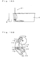
- the holding member 61 is moved to a medicine envelope reception position. Once the medicine envelope is fed, the support plate 9 is moved from an inclined reception position to a standing delivery position. At this point, the motor 65 is driven to rotate the drive disk 72 counterclockwise so as to position the both nip rollers 80 and 83 closer to each other as shown in FIG. 14. Then, the both nip rollers 80, 83 are horizontally moved, and the upper part of the medicine envelope is folded along the support plate 9 before the both nip rollers 80, 83 are lowered so as to be positioned on the both sides of the support plate 9. As a result, the upper part of the medicine envelope is two folded. In this state, the holding member 61 is raised so that by the rotation of the rotating piece 11, the medicine envelope is lifted while being held between the both nip rollers 80 and 83 as with the first embodiment.
- the medicine envelope lifted from the support plate 9 is moved toward the upper side of the bucket 4 by the horizontal movement of the holding member 61. Then, as shown in FIG. 15, after the holding member 61 is lowered, the medicine envelope is moved obliquely downward.
- the motor 65 When the medicine envelope is moved obliquely downward, the motor 65 is driven to rotate the drive disk 72 clockwise as shown in FIG. 15(b).
- the first arm 74 does not rotate since the guide shaft 73 simply slides along the long hole 76 and therefore an initial state is maintained.
- the second arm 75 moves upward with the rotation of the drive disk 72. Consequently, the second nip arm 82 uplifts the second connecting shaft 81, and rotates counterclockwise about the spindle 82a.
- the spindle 82a is in contact with the one-way clutch 78, the first nip arm 79 rotates counterclockwise with the second nip arm 82.
- the held state of the medicine envelope by the first nip roller 80 and the second nip roller 83 is maintained, and only the first nip arm 79 and the second nip arm 82 are inclined. Because of this, when the medicine envelope is placed on the bottom surface of the bucket 4, the medicine envelope can be inclined with the twofold portion being positioned on the lower side, making it possible to appropriately prevent the medicine envelope from opening.
- the holding member 61 it becomes possible to implement a natural operation such as holding the medicine envelope manually and accommodating it in the bucket 4, and to securely prevent the opening part of the medicine envelope from opening and the inside inject from leaking.
Landscapes
- Engineering & Computer Science (AREA)
- Mechanical Engineering (AREA)
- Basic Packing Technique (AREA)
- Sheets, Magazines, And Separation Thereof (AREA)
- Materials For Medical Uses (AREA)
- Supply Of Fluid Materials To The Packaging Location (AREA)
- Medical Preparation Storing Or Oral Administration Devices (AREA)
- External Artificial Organs (AREA)
- Catching Or Destruction (AREA)
Abstract
Description
Claims (8)
- A medicine envelope feeder, comprising:a support member for supporting one face of a medicine envelope storing injection excluding a tolerance for bending starting from an upper end opening part;a vertically movable holding member composed of a guide part for guiding the other face of the medicine envelope at least in a specified range exceeding the tolerance for bending starting from the upper end opening part, and a pressing part which is vertically movable along the guide part and is lowered for folding and pressing the medicine envelope along the support member, whereinat least a coefficient of friction of the pressing part is made larger than that of the support member, so that only the medicine envelope can be raised while being held between the guide part and the pressing part when the holding member is raised.
- The medicine envelope feeder as defined in Claim 1, wherein a part of the support member held between the guide part and the pressing part of the holding member is composed of a rotating piece rotatable about one end part.
- The medicine envelope feeder as defined in Claim 1 or 2, wherein the support member is provided in a rotatable manner about a lower end part and comprises medicine envelope detection means for detecting that the medicine envelope is fed, drive means for rotary-driving the support member by the medicine envelope detection means detecting the medicine envelope, and rotating position detecting means for detecting that the support member is rotated in a state the medicine envelope is held between the support member and the guide part of the holding member.
- The medicine envelope feeder as defined in any one of Claims 1 to 3, wherein the holding member is capable of moving in horizontal direction, and comprises a rotatable contact piece which is brought into contact with one surface of the medicine envelope as the holding member moves in horizontal direction when the held medicine envelope is fed to the bucket.
- The medicine envelope feeder as defined in any one of Claims 1 to 4, wherein the holding member comprises an inclined face which is provided on a lower end portion of the guide part and is gradually inclined from the pressing part toward a lower side, so that by moving the pressing part along the inclined face of the guide part, the held medicine envelope can be inclined with a folded side facing down.
- The medicine envelope feeder as defined in Claim 4, wherein the holding member further comprises an elastic pressing piece for pressing an upper folded side of the medicine envelope after retaining the medicine envelope on a bottom surface of the bucket by the contact piece.
- A medicine envelope feeder, comprising:a support member for supporting one face of a medicine envelope storing injection excluding a tolerance for bending starting from an upper end opening part;a vertically movable holding member composed of a pair of nip arms which are provided in a rotatable manner and have nip rollers at respective top ends for folding a tolerance for bending of the medicine envelope by one nip roller as the holding member is horizontally moved, and for holding the medicine envelope in a twofold state by lowering the both nip rollers so as to be positioned on both sides of the support member, whereinat least a coefficient of friction of the nip rollers is made larger than that of the support member, so that only the medicine envelope can be raised while being held between the both nip rollers when the holding member is raised.
- The medicine envelope feeder as defined in Claim 7, wherein a rotating angle of the nip arms in the holding member can be changed according to conditions of the medicine envelope.
Priority Applications (1)
| Application Number | Priority Date | Filing Date | Title |
|---|---|---|---|
| EP08163616A EP1997734A3 (en) | 2002-01-16 | 2003-01-10 | Medicine envelope feeder |
Applications Claiming Priority (5)
| Application Number | Priority Date | Filing Date | Title |
|---|---|---|---|
| JP2002007583 | 2002-01-16 | ||
| JP2002007583 | 2002-01-16 | ||
| JP2002032703 | 2002-02-08 | ||
| JP2002032703 | 2002-02-08 | ||
| PCT/JP2003/000142 WO2003059744A1 (en) | 2002-01-16 | 2003-01-10 | Chemical bag feeder |
Related Child Applications (1)
| Application Number | Title | Priority Date | Filing Date |
|---|---|---|---|
| EP08163616A Division EP1997734A3 (en) | 2002-01-16 | 2003-01-10 | Medicine envelope feeder |
Publications (3)
| Publication Number | Publication Date |
|---|---|
| EP1473229A1 true EP1473229A1 (en) | 2004-11-03 |
| EP1473229A4 EP1473229A4 (en) | 2007-03-21 |
| EP1473229B1 EP1473229B1 (en) | 2009-05-27 |
Family
ID=26625539
Family Applications (2)
| Application Number | Title | Priority Date | Filing Date |
|---|---|---|---|
| EP08163616A Withdrawn EP1997734A3 (en) | 2002-01-16 | 2003-01-10 | Medicine envelope feeder |
| EP03701054A Expired - Lifetime EP1473229B1 (en) | 2002-01-16 | 2003-01-10 | Medicine envelope feeder |
Family Applications Before (1)
| Application Number | Title | Priority Date | Filing Date |
|---|---|---|---|
| EP08163616A Withdrawn EP1997734A3 (en) | 2002-01-16 | 2003-01-10 | Medicine envelope feeder |
Country Status (11)
| Country | Link |
|---|---|
| US (1) | US7412809B2 (en) |
| EP (2) | EP1997734A3 (en) |
| JP (1) | JP4242289B2 (en) |
| KR (1) | KR100901742B1 (en) |
| CN (1) | CN100460281C (en) |
| AT (1) | ATE432219T1 (en) |
| CA (1) | CA2474010A1 (en) |
| DE (1) | DE60327738D1 (en) |
| NO (1) | NO20043384L (en) |
| TW (1) | TWI294392B (en) |
| WO (1) | WO2003059744A1 (en) |
Cited By (1)
| Publication number | Priority date | Publication date | Assignee | Title |
|---|---|---|---|---|
| WO2016088079A1 (en) * | 2014-12-04 | 2016-06-09 | Rexam Beverage Can South America S.A. | Process for managing a set of stacked lids inserted in a packaging, transportation device for the set formed of stacked lids inserted in a packaging, and production system for sets of palletized lids |
Families Citing this family (13)
| Publication number | Priority date | Publication date | Assignee | Title |
|---|---|---|---|---|
| US5771657A (en) * | 1996-05-07 | 1998-06-30 | Merck Medco Managed Care, Inc. | Automatic prescription filling, sorting and packaging system |
| US7527261B2 (en) | 2006-07-13 | 2009-05-05 | Lockheed Martin Corporation | Mailpiece container for stacking mixed mail and method for stacking mail therein |
| US7748199B2 (en) | 2006-11-28 | 2010-07-06 | Align Technology, Inc. | System and method for packaging of mass-fabricated custom items |
| JP4929022B2 (en) * | 2007-04-10 | 2012-05-09 | 高園産業株式会社 | Dispensing device sheet recovery method and apparatus |
| AT509141A1 (en) * | 2009-11-23 | 2011-06-15 | Herwig Worff | METHOD FOR CLOSING A BAG |
| US9334129B2 (en) * | 2012-06-05 | 2016-05-10 | Pitney Bowes Inc. | Method and apparatus for automated filling of a mail tray from a vertical stacker |
| US9150119B2 (en) | 2013-03-15 | 2015-10-06 | Aesynt Incorporated | Apparatuses, systems, and methods for anticipating and delivering medications from a central pharmacy to a patient using a track based transport system |
| US9511945B2 (en) | 2012-10-12 | 2016-12-06 | Aesynt Incorporated | Apparatuses, systems, and methods for transporting medications from a central pharmacy to a patient in a healthcare facility |
| CN105775261B (en) * | 2016-04-29 | 2018-07-27 | 青岛三维海容机电有限公司 | A kind of chemical bag feeder |
| JP7293713B2 (en) | 2019-02-25 | 2023-06-20 | 京セラドキュメントソリューションズ株式会社 | Gripping mechanism and assembly device |
| CN110422369B (en) * | 2019-09-06 | 2021-07-16 | 福建省全味食品有限公司 | Edge-folding tail-sealing machine for nut packaging |
| DE102022110826A1 (en) * | 2022-05-03 | 2023-11-09 | Tt Innovation Ag | Device for manipulating bags containing containers |
| CN116062607B (en) * | 2023-03-07 | 2023-06-20 | 菏泽市瑞祺医疗器械有限公司 | A special spreader for lifting raw materials of traditional Chinese medicine decoction pieces |
Family Cites Families (22)
| Publication number | Priority date | Publication date | Assignee | Title |
|---|---|---|---|---|
| US1605737A (en) * | 1926-05-26 | 1926-11-02 | George C Hume | Paper holder |
| US3653708A (en) * | 1969-05-16 | 1972-04-04 | Amerota Products Corp | Gripping device |
| SU1129167A1 (en) * | 1983-06-06 | 1984-12-15 | Центральная Экспериментально-Исследовательская Конструкторско-Технологическая Лаборатория Химизации Сельского Хозяйства (Цэлхим)Мсх Ссср | Load engaging device for bagged cargo |
| US4632444A (en) * | 1985-05-03 | 1986-12-30 | Rca Corporation | Robot hand |
| US4648233A (en) * | 1985-05-29 | 1987-03-10 | B-Bar-B, Inc. | Apparatus for handling liquid filled flexible plastic bags |
| DE3690749T1 (en) * | 1986-06-20 | 1988-07-14 | ||
| DE3704051A1 (en) * | 1987-02-10 | 1988-08-18 | Veith Gmbh Co Gustav Georg | CLAMP |
| DE3814617A1 (en) * | 1988-04-29 | 1989-11-09 | Fraunhofer Ges Forschung | GRIP DEVICE |
| US4996820A (en) * | 1988-10-19 | 1991-03-05 | Harrison Transplanter Corporation | Tagging machine for seedling transplants |
| US5060455A (en) * | 1990-06-28 | 1991-10-29 | Ameco Corporation | Robotic case packing system and method |
| US5303531A (en) * | 1992-02-14 | 1994-04-19 | Doboy Packaging Machinery, Inc. | Packaging machine |
| US5611193A (en) * | 1995-01-31 | 1997-03-18 | Hudson Control Group, Inc. | Two-axis article loader/unloader |
| AUPN186295A0 (en) * | 1995-03-21 | 1995-04-13 | Herdgraph Pty Ltd | Lifting device |
| US5771667A (en) * | 1996-11-06 | 1998-06-30 | James R. McGregor | Bag filling, closing, and sealing machine |
| JPH10323380A (en) * | 1997-03-25 | 1998-12-08 | Yuyama Seisakusho:Kk | Bag for sorting ampoules |
| JP4121606B2 (en) | 1997-09-12 | 2008-07-23 | 株式会社湯山製作所 | Injection bag filling device |
| DE19746378A1 (en) * | 1997-10-21 | 1999-04-22 | Rovema Gmbh | Bag packing flap-folder has grip unit which folds open flap to closed position |
| JP4368956B2 (en) | 1998-03-24 | 2009-11-18 | 株式会社湯山製作所 | Ampoule bagging equipment |
| WO2004080809A1 (en) | 1998-06-30 | 2004-09-23 | Shoji Yuyama | Apparatus for bagging injections |
| JP4577918B2 (en) * | 1998-09-09 | 2010-11-10 | 株式会社湯山製作所 | Ampoule bagging equipment |
| DE19901496C1 (en) * | 1999-01-11 | 2000-11-30 | Mannesmann Ag | Clamping gripper for loads to be gripped from above |
| US6554337B2 (en) * | 2000-12-07 | 2003-04-29 | Homayoon Kazerooni | Mechanical grapple for grabbing and holding sacks and bags |
-
2003
- 2003-01-06 TW TW092100185A patent/TWI294392B/en active
- 2003-01-10 EP EP08163616A patent/EP1997734A3/en not_active Withdrawn
- 2003-01-10 US US10/501,594 patent/US7412809B2/en not_active Expired - Fee Related
- 2003-01-10 JP JP2003559866A patent/JP4242289B2/en not_active Expired - Fee Related
- 2003-01-10 DE DE60327738T patent/DE60327738D1/en not_active Expired - Lifetime
- 2003-01-10 WO PCT/JP2003/000142 patent/WO2003059744A1/en not_active Ceased
- 2003-01-10 CA CA002474010A patent/CA2474010A1/en not_active Abandoned
- 2003-01-10 CN CNB038021021A patent/CN100460281C/en not_active Expired - Fee Related
- 2003-01-10 EP EP03701054A patent/EP1473229B1/en not_active Expired - Lifetime
- 2003-01-10 KR KR1020047010469A patent/KR100901742B1/en not_active Expired - Fee Related
- 2003-01-10 AT AT03701054T patent/ATE432219T1/en not_active IP Right Cessation
-
2004
- 2004-08-13 NO NO20043384A patent/NO20043384L/en unknown
Cited By (3)
| Publication number | Priority date | Publication date | Assignee | Title |
|---|---|---|---|---|
| WO2016088079A1 (en) * | 2014-12-04 | 2016-06-09 | Rexam Beverage Can South America S.A. | Process for managing a set of stacked lids inserted in a packaging, transportation device for the set formed of stacked lids inserted in a packaging, and production system for sets of palletized lids |
| US20170327256A1 (en) * | 2014-12-04 | 2017-11-16 | Rexam Beverage Can South America S.A. | Method of managing a set of lids, stacked and inserted in a package, transport device for transporting a set of stacked lids and inserted in a package, and system for producing palletized set of lids |
| US10654601B2 (en) * | 2014-12-04 | 2020-05-19 | Ball Beverage Can South America S.A. | Method of managing a set of lids, stacked and inserted in a package, transport device for transporting a set of stacked lids and inserted in a package, and system for producing palletized set of lids |
Also Published As
| Publication number | Publication date |
|---|---|
| EP1997734A2 (en) | 2008-12-03 |
| EP1473229B1 (en) | 2009-05-27 |
| NO20043384L (en) | 2004-10-11 |
| ATE432219T1 (en) | 2009-06-15 |
| CN100460281C (en) | 2009-02-11 |
| TW200302188A (en) | 2003-08-01 |
| US20050161875A1 (en) | 2005-07-28 |
| TWI294392B (en) | 2008-03-11 |
| KR100901742B1 (en) | 2009-06-10 |
| DE60327738D1 (en) | 2009-07-09 |
| EP1473229A4 (en) | 2007-03-21 |
| CA2474010A1 (en) | 2003-07-24 |
| JPWO2003059744A1 (en) | 2005-05-19 |
| KR20040077700A (en) | 2004-09-06 |
| JP4242289B2 (en) | 2009-03-25 |
| WO2003059744A1 (en) | 2003-07-24 |
| US7412809B2 (en) | 2008-08-19 |
| EP1997734A3 (en) | 2008-12-10 |
| CN1615240A (en) | 2005-05-11 |
Similar Documents
| Publication | Publication Date | Title |
|---|---|---|
| EP1473229B1 (en) | Medicine envelope feeder | |
| JP4551396B2 (en) | Chemical dispensing device | |
| US6478185B2 (en) | Tablet vessel feed apparatus | |
| TW201014767A (en) | Card raising/lowering device, card carrying-out/carrying-in device, and card issue/recovery apparatus | |
| JP5817865B2 (en) | Chemical tray feeder | |
| EP1371558B1 (en) | Tablet packing apparatus | |
| US20060272283A1 (en) | Packaging system | |
| US20110000815A1 (en) | Ampule container | |
| CN101405187A (en) | Machine for filling bag with medicine | |
| WO2003022719A1 (en) | Medicine feeder | |
| US7264238B2 (en) | Feed paper apparatus | |
| CN100588596C (en) | Paper Cassettes and Information Processing Devices | |
| JP2007031069A (en) | Sheet feeding device and image forming device | |
| JPH0543066A (en) | Paper feeding device | |
| JPH11263449A (en) | Paper feeder | |
| JP3184386B2 (en) | Paper feeder | |
| JPH04350047A (en) | Sheet body feeding device | |
| JPH06107343A (en) | Paper feeder | |
| JP2006143346A (en) | Paper feeding device for image forming device | |
| JP3498860B2 (en) | Secret label sticking device | |
| JPH07285684A (en) | Paper feeder | |
| JP3008164U (en) | Newspaper sending device of newspaper vending machine | |
| JPH11208908A (en) | Automatic paper feeder | |
| JP2013240455A (en) | Medicine dispenser | |
| JPH0382543A (en) | Sheet material feed apparatus |
Legal Events
| Date | Code | Title | Description |
|---|---|---|---|
| PUAI | Public reference made under article 153(3) epc to a published international application that has entered the european phase |
Free format text: ORIGINAL CODE: 0009012 |
|
| 17P | Request for examination filed |
Effective date: 20040805 |
|
| AK | Designated contracting states |
Kind code of ref document: A1 Designated state(s): AT BE BG CH CY CZ DE DK EE ES FI FR GB GR HU IE IT LI LU MC NL PT SE SI SK TR |
|
| A4 | Supplementary search report drawn up and despatched |
Effective date: 20070220 |
|
| RIC1 | Information provided on ipc code assigned before grant |
Ipc: B65B 35/16 20060101ALI20070214BHEP Ipc: B65B 5/08 20060101AFI20030731BHEP Ipc: B65B 7/08 20060101ALI20070214BHEP Ipc: B65B 5/10 20060101ALI20070214BHEP |
|
| 17Q | First examination report despatched |
Effective date: 20080508 |
|
| RTI1 | Title (correction) |
Free format text: MEDICINE ENVELOPE FEEDER |
|
| GRAP | Despatch of communication of intention to grant a patent |
Free format text: ORIGINAL CODE: EPIDOSNIGR1 |
|
| GRAS | Grant fee paid |
Free format text: ORIGINAL CODE: EPIDOSNIGR3 |
|
| GRAA | (expected) grant |
Free format text: ORIGINAL CODE: 0009210 |
|
| AK | Designated contracting states |
Kind code of ref document: B1 Designated state(s): AT BE BG CH CY CZ DE DK EE ES FI FR GB GR HU IE IT LI LU MC NL PT SE SI SK TR |
|
| REG | Reference to a national code |
Ref country code: GB Ref legal event code: FG4D |
|
| REG | Reference to a national code |
Ref country code: CH Ref legal event code: EP |
|
| REG | Reference to a national code |
Ref country code: IE Ref legal event code: FG4D |
|
| REF | Corresponds to: |
Ref document number: 60327738 Country of ref document: DE Date of ref document: 20090709 Kind code of ref document: P |
|
| PG25 | Lapsed in a contracting state [announced via postgrant information from national office to epo] |
Ref country code: FI Free format text: LAPSE BECAUSE OF FAILURE TO SUBMIT A TRANSLATION OF THE DESCRIPTION OR TO PAY THE FEE WITHIN THE PRESCRIBED TIME-LIMIT Effective date: 20090527 Ref country code: PT Free format text: LAPSE BECAUSE OF FAILURE TO SUBMIT A TRANSLATION OF THE DESCRIPTION OR TO PAY THE FEE WITHIN THE PRESCRIBED TIME-LIMIT Effective date: 20090927 Ref country code: AT Free format text: LAPSE BECAUSE OF FAILURE TO SUBMIT A TRANSLATION OF THE DESCRIPTION OR TO PAY THE FEE WITHIN THE PRESCRIBED TIME-LIMIT Effective date: 20090527 |
|
| PG25 | Lapsed in a contracting state [announced via postgrant information from national office to epo] |
Ref country code: SI Free format text: LAPSE BECAUSE OF FAILURE TO SUBMIT A TRANSLATION OF THE DESCRIPTION OR TO PAY THE FEE WITHIN THE PRESCRIBED TIME-LIMIT Effective date: 20090527 Ref country code: SE Free format text: LAPSE BECAUSE OF FAILURE TO SUBMIT A TRANSLATION OF THE DESCRIPTION OR TO PAY THE FEE WITHIN THE PRESCRIBED TIME-LIMIT Effective date: 20090827 |
|
| PG25 | Lapsed in a contracting state [announced via postgrant information from national office to epo] |
Ref country code: EE Free format text: LAPSE BECAUSE OF FAILURE TO SUBMIT A TRANSLATION OF THE DESCRIPTION OR TO PAY THE FEE WITHIN THE PRESCRIBED TIME-LIMIT Effective date: 20090527 Ref country code: DK Free format text: LAPSE BECAUSE OF FAILURE TO SUBMIT A TRANSLATION OF THE DESCRIPTION OR TO PAY THE FEE WITHIN THE PRESCRIBED TIME-LIMIT Effective date: 20090527 Ref country code: CZ Free format text: LAPSE BECAUSE OF FAILURE TO SUBMIT A TRANSLATION OF THE DESCRIPTION OR TO PAY THE FEE WITHIN THE PRESCRIBED TIME-LIMIT Effective date: 20090527 Ref country code: ES Free format text: LAPSE BECAUSE OF FAILURE TO SUBMIT A TRANSLATION OF THE DESCRIPTION OR TO PAY THE FEE WITHIN THE PRESCRIBED TIME-LIMIT Effective date: 20090907 |
|
| PG25 | Lapsed in a contracting state [announced via postgrant information from national office to epo] |
Ref country code: SK Free format text: LAPSE BECAUSE OF FAILURE TO SUBMIT A TRANSLATION OF THE DESCRIPTION OR TO PAY THE FEE WITHIN THE PRESCRIBED TIME-LIMIT Effective date: 20090527 Ref country code: BE Free format text: LAPSE BECAUSE OF FAILURE TO SUBMIT A TRANSLATION OF THE DESCRIPTION OR TO PAY THE FEE WITHIN THE PRESCRIBED TIME-LIMIT Effective date: 20090527 |
|
| PG25 | Lapsed in a contracting state [announced via postgrant information from national office to epo] |
Ref country code: BG Free format text: LAPSE BECAUSE OF FAILURE TO SUBMIT A TRANSLATION OF THE DESCRIPTION OR TO PAY THE FEE WITHIN THE PRESCRIBED TIME-LIMIT Effective date: 20090827 |
|
| PLBE | No opposition filed within time limit |
Free format text: ORIGINAL CODE: 0009261 |
|
| STAA | Information on the status of an ep patent application or granted ep patent |
Free format text: STATUS: NO OPPOSITION FILED WITHIN TIME LIMIT |
|
| 26N | No opposition filed |
Effective date: 20100302 |
|
| PG25 | Lapsed in a contracting state [announced via postgrant information from national office to epo] |
Ref country code: MC Free format text: LAPSE BECAUSE OF NON-PAYMENT OF DUE FEES Effective date: 20100131 |
|
| REG | Reference to a national code |
Ref country code: CH Ref legal event code: PL |
|
| REG | Reference to a national code |
Ref country code: IE Ref legal event code: MM4A |
|
| PG25 | Lapsed in a contracting state [announced via postgrant information from national office to epo] |
Ref country code: CH Free format text: LAPSE BECAUSE OF NON-PAYMENT OF DUE FEES Effective date: 20100131 Ref country code: LI Free format text: LAPSE BECAUSE OF NON-PAYMENT OF DUE FEES Effective date: 20100131 Ref country code: GR Free format text: LAPSE BECAUSE OF FAILURE TO SUBMIT A TRANSLATION OF THE DESCRIPTION OR TO PAY THE FEE WITHIN THE PRESCRIBED TIME-LIMIT Effective date: 20090828 |
|
| PG25 | Lapsed in a contracting state [announced via postgrant information from national office to epo] |
Ref country code: IE Free format text: LAPSE BECAUSE OF NON-PAYMENT OF DUE FEES Effective date: 20100110 |
|
| PG25 | Lapsed in a contracting state [announced via postgrant information from national office to epo] |
Ref country code: IT Free format text: LAPSE BECAUSE OF FAILURE TO SUBMIT A TRANSLATION OF THE DESCRIPTION OR TO PAY THE FEE WITHIN THE PRESCRIBED TIME-LIMIT Effective date: 20090527 |
|
| PG25 | Lapsed in a contracting state [announced via postgrant information from national office to epo] |
Ref country code: CY Free format text: LAPSE BECAUSE OF FAILURE TO SUBMIT A TRANSLATION OF THE DESCRIPTION OR TO PAY THE FEE WITHIN THE PRESCRIBED TIME-LIMIT Effective date: 20090527 |
|
| PG25 | Lapsed in a contracting state [announced via postgrant information from national office to epo] |
Ref country code: HU Free format text: LAPSE BECAUSE OF FAILURE TO SUBMIT A TRANSLATION OF THE DESCRIPTION OR TO PAY THE FEE WITHIN THE PRESCRIBED TIME-LIMIT Effective date: 20091128 Ref country code: LU Free format text: LAPSE BECAUSE OF NON-PAYMENT OF DUE FEES Effective date: 20100110 |
|
| PG25 | Lapsed in a contracting state [announced via postgrant information from national office to epo] |
Ref country code: TR Free format text: LAPSE BECAUSE OF FAILURE TO SUBMIT A TRANSLATION OF THE DESCRIPTION OR TO PAY THE FEE WITHIN THE PRESCRIBED TIME-LIMIT Effective date: 20090527 |
|
| REG | Reference to a national code |
Ref country code: FR Ref legal event code: PLFP Year of fee payment: 13 |
|
| PGFP | Annual fee paid to national office [announced via postgrant information from national office to epo] |
Ref country code: NL Payment date: 20150129 Year of fee payment: 13 |
|
| PGFP | Annual fee paid to national office [announced via postgrant information from national office to epo] |
Ref country code: DE Payment date: 20150121 Year of fee payment: 13 |
|
| PGFP | Annual fee paid to national office [announced via postgrant information from national office to epo] |
Ref country code: GB Payment date: 20150121 Year of fee payment: 13 Ref country code: FR Payment date: 20150122 Year of fee payment: 13 |
|
| REG | Reference to a national code |
Ref country code: DE Ref legal event code: R119 Ref document number: 60327738 Country of ref document: DE |
|
| GBPC | Gb: european patent ceased through non-payment of renewal fee |
Effective date: 20160110 |
|
| REG | Reference to a national code |
Ref country code: NL Ref legal event code: MM Effective date: 20160201 |
|
| REG | Reference to a national code |
Ref country code: FR Ref legal event code: ST Effective date: 20160930 |
|
| PG25 | Lapsed in a contracting state [announced via postgrant information from national office to epo] |
Ref country code: DE Free format text: LAPSE BECAUSE OF NON-PAYMENT OF DUE FEES Effective date: 20160802 Ref country code: GB Free format text: LAPSE BECAUSE OF NON-PAYMENT OF DUE FEES Effective date: 20160110 |
|
| PG25 | Lapsed in a contracting state [announced via postgrant information from national office to epo] |
Ref country code: NL Free format text: LAPSE BECAUSE OF NON-PAYMENT OF DUE FEES Effective date: 20160201 Ref country code: FR Free format text: LAPSE BECAUSE OF NON-PAYMENT OF DUE FEES Effective date: 20160201 |