Cross-Reference to Related Application
-
The entire disclosure, including the specification,
claims, drawings and abstract, of Japanese Patent Application
No. 2002-27799 (filed on February 5, 2002) is incorporated in
this application by reference.
Field of the Invention
-
This invention relates to an automatic air supply
mechanism for a pneumatic tire for automatically supplying air
into a pneumatic tire rotatably mounted on an axle, and to a
pneumatic tire connecting device for use in the automatic air
supply mechanism.
Background Arts
-
Pneumatic tires containing air are mounted on wheels of
a bicycle or a car. Even if air has been pumped into such
pneumatic tires until the air pressure therein reaches a
prescribed value, the air gradually escapes therefrom and the
air pressure therein decreases with a lapse of time. A large
decrease in tire pressure causes problems, such as making
steering difficult. Thus, when the air pressure in pneumatic
tires has decreased to a value which is much lower than a
prescribed value, air must be supplied thereinto.
-
However, when the air pressure in a pneumatic tire is lower
than a prescribed value, it is difficult to recognize it from
the appearance thereof. Thus, in some cases, the pneumatic tire
is used as it is, which might cause a danger. Also, it is
troublesome to supply air into a pneumatic tire with an air
supply pump or the like every time the air pressure therein
decreases.
Disclosure of the Invention
-
The present invention has been made in view of the above
circumstances and it is, therefore, an object of the present
invention to provide an automatic air supply mechanism for a
pneumatic tire which can automatically supply air into a
pneumatic tire by rotation of the pneumatic tire with respect
to an axle when the air pressure therein becomes lower than a
prescribed value and a pneumatic tire connecting device
therefor.
-
The automatic air supply mechanism for a pneumatic tire
according to this invention is an automatic air supply mechanism
for a pneumatic tire for automatically supplying air into a
pneumatic tire mounted on a wheel body rotatable with respect
to an axle, comprising an air feeding section provided on a wheel
and connected to the pneumatic tire in air flow communication
for feeding air into the pneumatic tire, the air feeding section
being provided with a compression section which can compress
air when the wheel body is rotated with respect to the axle.
-
The pneumatic tire connecting device according to this
invention is a pneumatic tire connecting device for connecting
an automatic air supply mechanism for a pneumatic tire for
automatically supplying air into a pneumatic tire mounted on
a wheel body rotatable about an axle to a pneumatic tire,
comprising a tire connection section connected to the pneumatic
tire, an automatic supply mechanism connection section
connected to the automatic air supply mechanism, a pneumatic
tire connecting air passage provided between the tire
connection section and the automatic supply mechanism
connection section in air flow communication, and an air
introducing hole communicating the pneumatic tire connecting
air passage with the outside, the pneumatic tire connecting air
passage being configured to be able to pass air from the
automatic air supply mechanism to the pneumatic tire by being
connected to an air passage provided in the automatic air supply
mechanism when the automatic supply mechanism connection
section and the automatic air supply mechanism are connected,
the tire connection section having a valve hole opened to
communicate the pneumatic tire connecting air passage with the
outside and provided with a valve mounting part to which a check
valve for preventing backflow of air from the pneumatic tire
to the pneumatic tire connecting air passage can be attached,
the air introducing hole being provided with an air introducing
hole backflow preventing means for preventing air from escaping
from the pneumatic tire connecting air passage to the outside,
whereby, when the check valve is attached to the valve mounting
part, the valve hole is closed by the check valve so that backflow
of air from the pneumatic tire to the pneumatic tire connecting
air passage can be prevented in connecting the tire connection
section and the pneumatic tire, and when air is fed from the
pneumatic tire connecting air passage to the valve hole, the
valve hole is opened so that air can enter the pneumatic tire
from the pneumatic tire connecting air passage.
-
Although the features of this invention can be described
widely as above, the constitution and details, together with
the objects and features, of this invention will be more
apparent from the following disclosure taken in conjunction
with the accompanying drawings.
Brief Description of Drawings
-
- FIG .1 is a side view of a bicycle wheel provided with
an automatic air supply mechanism for a pneumatic tire according
to a first embodiment of this invention;
- FIG. 2 is an enlarged cross-sectional explanatory view
taken along the line II-II in FIG. 1;
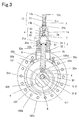
- FIG. 3 is a longitudinal cross-sectional explanatory view
taken along the line III-III in FIG. 2;
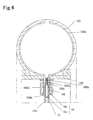
- FIG. 4 is an enlarged cross-sectional explanatory view
taken along the line IV-IV in FIG. 1;
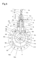
- FIG. 5 is a cross-sectional explanatory view illustrating
the state where air in a compression chamber is compressed;
- FIG. 6 is an enlarged cross-sectional explanatory view
of an essential part of a bicycle wheel provided with an
automatic air supply mechanism for a pneumatic tire according
to a second embodiment of this invention;
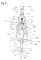
- FIG. 7 is a cross-sectional explanatory view illustrating
the state where air in a compression chamber is compressed in
the second embodiment;
- FIG. 8 is a cross-sectional explanatory view of an
essential part of a bicycle wheel provided with an automatic
air supply mechanism for a pneumatic tire according to a third
embodiment of this invention;
- FIG. 9 is an enlarged cross-sectional explanatory view
of an essential part in FIG. 8;
- FIG. 10 is a cross-sectional explanatory view
illustrating the state where air in a compression chamber is
compressed in the third embodiment;
- FIG. 11 is a cross-sectional explanatory view of a car
wheel provided with an automatic air supply mechanism for a
pneumatic tire according to a fourth embodiment of this
invention;
- FIG. 12 is an enlarged cross-sectional explanatory view
taken along the line XII-XII in FIG. 11;
- FIG. 13 is an enlarged cross-sectional explanatory view
illustrating the state where a pneumatic tire connection
section and a valve of a pneumatic tire are connected in the
fourth embodiment;
- FIG. 14 is an enlarged cross-sectional explanatory view
illustrating the state where the air pressure in a constant
pressure maintaining chamber is so higher than that in a
pneumatic tire that the air in the constant pressure maintaining
chamber is pressing a valve of the pneumatic tire and flowing
into the pneumatic tire;
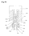
- FIG. 15 is an enlarged cross-sectional explanatory view
illustrating the state where the air pressures in the constant
pressure maintaining chamber and the pneumatic tire have become
equal;
- FIG. 16 is an enlarged cross-sectional explanatory view
of another embodiment of an essential part of an air feeding
section;
- FIG. 17 is a side view of a bicycle wheel provided with
an automatic air supply mechanism for a pneumatic tire according
to a fifth embodiment;
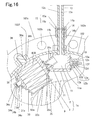
- FIG. 18 is an enlarged cross-sectional explanatory view
of essential parts of a cam and a cam contact part in the fifth
embodiment;
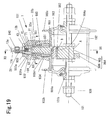
- FIG. 19 is an enlarged cross-sectional explanatory view
of an essential part of a bicycle wheel provided with an
automatic air supply mechanism for a pneumatic tire according
to a sixth embodiment of this invention;
- FIG. 20 is a cross-sectional explanatory view taken along
the line XX-XX in FIG. 19;
- FIG. 21(A) is an enlarged cross-sectional explanatory
view taken along the line XXI-XXI in FIG. 19;
- FIG. 21(B) is an enlarged cross-sectional explanatory
view illustrating the positional relation between a casing
operation member and a casing support member after an operation
to rotate a compression chamber to reduce the compression ratio
therein;
- FIG. 22(A) is an enlarged cross-sectional view of a
compression section;
- FIG. 22(B) is an enlarged cross-sectional explanatory
view of the compression section after the compression ratio
therein shown in FIG. 22(A) has been adjusted with compression
ratio adjusting means;
- FIG. 23 is an enlarged, partially cross-sectional, side
view of a pneumatic tire connecting device, and
- FIG. 24 is an enlarged, partially cross-sectional, side
view of another embodiment of the pneumatic tire connecting
device.
-
Best Mode for Carrying Out the Invention
-
Description will be hereinafter made of an embodiment of
this invention based on the drawings.
-
FIG .1 is a side view of a bicycle wheel provided with
an automatic air supply mechanism for a pneumatic tire according
to a first embodiment of this invention. FIG. 2 is an enlarged
cross-sectional explanatory view taken along the line II-II in
FIG. 1. FIG. 3 is an enlarged cross-sectional view taken along
the line III-III in FIG. 2.
-
The automatic air supply mechanism for a pneumatic tire
of the first embodiment is provided on a bicycle wheel 100. The
bicycle wheel 100 provided with the automatic air supply
mechanism 1 for a pneumatic tire has an axle 101 and a wheel
body 110 rotatable with respect to the axle 101. The axle 101
has thread parts 101a on the outer periphery as shown in FIG.
2.
-
As shown in FIG. 1, the wheel body 110 has a hub 102, a
pneumatic tire 103 and the automatic air supply mechanism 1.
As shown in FIG. 2, the hub 102 has a cylindrical body, and has
inner peripheral sides on which steel ball roller bearings 102a
and 102a are respectively provided on both right and left sides
thereof. The steel ball roller bearings 102a and 102a are
supported for rotation about the central axis O3 of the axle
101 by ball pushers 101b and 101b, respectively, threaded on
the axle 101 via steel balls 107, ..., 107. The hub 102 has outer
peripheral sides to which collars 102c and 102c having a
plurality of spoke holes 102b, ..., 102b are respectively secured
on both right and left sides thereof. In the spoke holes 102b,
..., 102b of the collars 102c and 102c are engaged the base end
sides of spokes 104. As shown in FIG. 1, the distal end sides
of the spokes 104 are fixed to a rim 105. Thereby, the rim 105
is fixed to the hub 102 and allowed to rotate with respect to
the axle 101.
-
The pneumatic tire 103 is removably fitted on the rim 105
and thus is rotatable together with the rim 105 with respect
to the axle 101. As shown in FIG. 4, an air holding tube 103b
as an air holding section for holding air is provided in the
pneumatic tire 103.
-
The air holding tube 103b has a valve 106 through which
air is supplied and discharged. The valve 106 is constituted
of a cylindrical body and has an air supply port 106a at the
lower end as seen in the drawing and a valve hole 106b at the
upper end as seen the drawing. The valve hole 106b is closed
by a cylindrical check valve 106c of a synthetic rubber fitted
on the outer periphery of the valve 106.
-
The valve 106 is received in a cylindrical valve mounting
piece 103c attached to the air holding tube 103b and is prevented
from coming off by a valve fixing nut 106d threaded on the valve
mounting piece 103c. When air is fed through the air supply
port 106a against the elasticity of the check valve 106c closing
the valve hole 106b with an air pump or the like, the air pushes
away the check valve 106c and enters the air holding tube 103b.
After air has been fed into the air holding tube 103b, the check
valve 106c closes the valve hole 106 because of its elasticity.
Thereby, the air in the air holding tube 103b is prevented from
escaping through the valve hole 106b. The check valve 106c,
the valve mounting piece 103c and the valve fixing nut 106d are
the same as those employed in an ordinary air holding tube 103b
for a bicycle.
-
The opposite ends of the axle 101 of the wheel 100
constituted as above are secured to a bicycle body via nuts 108
and 108 (shown in Fig. 2) , whereby the wheel body 110 is rotatably
attached to the bicycle body.
-
Description will be made of the automatic air supply
mechanism 1. The automatic air supply mechanism 1 for a
pneumatic tire for a bicycle of the first embodiment has an air
feeding section 1a for feeding air into the pneumatic tire 103
as shown in FIG. 2 and FIG. 3.
-
The air feeding section 1a has a compression section 3
for compressing air and a constant pressure maintaining section
2 for maintaining the pressure of air compressed in the
compression section 3 at a constant value.
-
The compression section 3 has a compression chamber 31
in which air is compressed and compression operation means 32
for performing operations to compress air in the compression
chamber 31.
-
The compression chamber 31 is formed in an inner casing
3a having a circular cross-section. The lower side of the inner
casing 3a as seen in FIG. 2 and FIG. 3 is fitted in an outer
casing 3b having a circular cross-section and supported thereby.
The outer casing 3b has hub fitting parts 30b at the lower end
as seen in FIG. 2 and FIG. 3. The hub fitting parts 30b are
secured to the outer periphery of the hub 102 via bolts 30c and
30c. Thereby, the inner casing 3a is attached to the outer
periphery of the hub 102 via the outer casing 3b and extends
outward from the outer periphery of the hub 102 in a radial
direction of the axle 101.
-
A partition 7 is provided in the inner casing 3a attached
to the hub 102 as above. The partition 7 allows the inside of
the inner casing 3a to be partitioned into the compression
chamber 31 on the lower side as seen in the drawings and a
hereinafter described constant pressure maintaining space part
13b of the constant pressure maintaining section 2. A
communication hole 71 is formed through the partition 7. The
compression chamber 31 and the constant pressure maintaining
space part 13b are connected in air flow communication by the
communication hole 71.
-
The communication hole 71 is provided with a check valve
4. The check valve 4, which serves as backflow preventing means
for preventing backflow of air from the constant pressure
maintaining section 2 to the compression chamber 31, is
constituted of a ball valve 4 disposed on the side of the constant
pressure maintaining section 2 in this embodiment. The ball
valve 4 has a ball 41, a ring-shaped ball receiving packing 42
of a synthetic rubber for receiving the ball, and a ball urging
coil spring 43 as an urging member for urging the ball 41 toward
the ball receiving packing 42. The ball 41 closes the
communication hall 71 from the side of the constant pressure
maintaining section 2 because of the urging force of the ball
urging coil spring 43.
-
The compression chamber 31 is provided with a suction hole
31a through which air is fed thereinto from the outside as shown
in FIG. 3. The compression chamber 31 is also provided with
a rod guiding port 37 at the lower side as seen in FIG. 2 and
FIG. 3.
-
The compression operation means 32 has a rod-like piston
rod 8 as a compression operation body extending in the radial
direction of the axle 101, and a cam 9. The piston rod 8 is
slidably inserted through the rod guiding port 37 of the
compression chamber 31. The upper part of the piston rod 8,
as seen in the drawings, extending outward in the radial
direction of the axle 101 is inserted in the compression chamber
31. The part of the piston rod 8 inserted in the compression
chamber 31 is provided with a disk-shaped sliding part 32a.
-
The sliding part 32a has a diameter which is generally
the same as the inside diameter of the compression chamber 31
and is slidable along the inside wall of the compression chamber
31 in the axial direction of the compression chamber 31. The
sliding part 32a is provided with a ring-shaped packing 32b of
a synthetic rubber.
-
The lower part of the piston rod 8, as seen in the drawing,
extends inward in the radial direction of the axle 101 through
the rod guiding port 37 of the compression chamber 31 and a piston
introducing hole 102d formed through the hub 102 to the inside
of the inner periphery of the hub 102. A cam contact part 32c
is provided on this part.
-
The cam contact part 32c comprises a roller shaft 32d,
and a pair of right and left rollers 32e and 32e rotatably
supported by the piston rod 8 via the roller shaft 32d as shown
in FIG. 2 in this embodiment. The both right and left ends of
the roller shaft 32d are protruded from the rollers 32e and 32e,
respectively. The rollers 32e and 32e of the cam contact part
32c constituted as above are in contact with a cam 9 secured
on the axle 101.
-
The cam 9 is constituted of a disk-like groove cam and
has a cam groove 92 formed around the entire periphery thereof.
The cam groove 92 has a cam face 92a defining the contour of
the cam 9 which is in contact with the rollers 32e and 32e and
on which the rollers 32e and 32e can run, and shaft contact parts
92b and 92b for receiving the roller shaft 32d of the cam contact
part 32c.
-
The cam face 92a is formed in a circle around the entire
periphery of the cam 9 with a prescribed depth from the outer
peripheral surface thereof. The shaft contact parts 92b and
92b are formed on opposite walls formed opposite the cam face
92a in the cam groove 92.
-
The cam contact part 32c of the piston rod 8 is located
in the cam groove 92, whereby the rollers 32e and 32e are in
contact with the cam face 92a. Since the roller shaft 32d is
in contact with the shaft contact parts 92b, the rollers 32e
and 32e in contact with the cam face 92a is prevented from
separating therefrom. Thus, the cam 9 in this embodiment
constitutes a positive motion cam, so that the cam 9 and the
rollers 32e and 32e of the piston rod 8 are maintained in constant
contact with each other.
-
An axle through hole 91 for receiving the axle 101 is
formed through the cam 9 as shown in FIG. 3. The center 02 of
the axle through hole 91 is a prescribed distance offset from
the center O1 of the cam face 92a and the shaft contact parts
92b and 92b.
-
After the axle 101 has been inserted through the axle
through hole 91, the cam 9 is secured to the axle 101 from both
right and left sides with cam fixing nuts 45 and 45 as shown
in FIG. 2. In this fixed state, the center O2 of the axle through
hole 91 coincides with the center of rotation O3 of the hub 102.
-
Thus, the position on the cam face 92a in contact with
the rollers 32e and 32e shown in FIG. 3 is a small radius part
A, where the distance from the center O2 of the axle through
hole 91 is smallest. The distance from the center O2 of the
axle through hole 91 gradually increases circumferentially, and
a position halfway around the circumference of the cam 9 from
the small radius part A is a large radius part B, where the
distance from the center O2 of the axle through hole 91 is
largest.
-
When the rollers 32e and 32e are at the small radius part
A of the cam face 92a, the sliding part 32a of the piston rod
8 is in its lowermost position in the compression chamber 31,
namely at the bottom dead center position A1 as shown in FIG.
3. When the rollers 32e and 32e are at the large radius part
B of the cam face 92a, the sliding part 32a of the piston rod
8 is in its uppermost position B1 in the compression chamber
31 as shown in FIG. 5.
-
The constant pressure maintaining section 2 of the air
feeding section 1a maintains the air pressure at a constant
value. The constant pressure maintaining section in this
embodiment is constituted of a connection section connecting
the compression section 3 and the pneumatic tire 103.
-
The connection section 13 comprises the constant pressure
maintaining space part 13b formed on the upper side in the
compression chamber 31 in the inner casing 3a by a partition
as seen in FIG. 2, a connection tube 21 and a connection pipe
13c.
-
The connection tube 21 has a cylindrical shape and has
an air passage 21a therein. The connection tube 21 has a base
end side which is attached to the inner casing 3 via a fixing
nut 21b with its end inserted in the pressure maintaining space
part 13b of the inner casing 3a. Thereby, the distal end side
of the connection tube 21 extends outward from the inner casing
3a in the radial direction of the axle 101. This attachment
allows the constant pressure maintaining space part 13b and the
air passage 21a to be connected in air flow communication.
-
The connection pipe 13c is made of an elastic material
and has an air passage 13a therein. The connection pipe 13c
is attached to the distal end of the connection tube 21 with
its end press-fitted over the outer periphery of the connection
tube 21. Thereby, the air passage 21a of the connection tube
21 and the air passage 13a of the connection pipe 13c are
connected and one air passage is formed in the connection
section 13. As a result, the constant pressure maintaining
space part 13b of the inner casing 3a and the connection pipe
13c are connected to each other.
-
As shown in FIG. 4, a pneumatic tire connection section
16 removably connectable to the pneumatic tire 103 is provided
at the distal end of the connection pipe 13c which is opposite
the side attached to the connection tube 21. The pneumatic tire
connection section 16 has a packing 16a and a nut engaging piece
16b engageable with the valve fixing nut 106d of the air holding
tube 103b. The nut engaging piece 16b is engaged with the valve
fixing nut 106d with the packing 16a in contact with an end of
the valve 106. Thereby, the distal end of the connection pipe
13c is connected to the air holding tube 103b in air flow
communication.
-
Description will be made of the operation of the automatic
air supply mechanism for a bicycle pneumatic tire of the first
embodiment. The axle 101 of the bicycle wheel 100 provided with
the automatic air supply mechanism for a bicycle pneumatic tire
is attached to a bicycle body. The pneumatic tire 103 is rotated
with respect to the axle 101 from the state shown in FIG. 2 where
the sliding part 32a is located at the bottom dead center
position A by, for example, running the bicycle. Then, the hub
102 is rotated by the rotation of the pneumatic tire 103 and
the rollers 32e of the piston rod 8 run on the cam face 92a of
the cam 9 with the hub 102 from the small radius part A toward
the large radius part B.
-
When the rollers 32e run, the piston rod 8 is pressed by
the cam 9 outward in the radial direction thereof, and moved.
Thus, the cam 9 functions as a pressing part for pressing the
piston rod 8. The movement of the piston rod 8 allows the
sliding part 32a to be slid in the compression chamber 31 along
the inside wall thereof from the bottom dead center position
A1 toward the top dead center position B1.
-
Then, when the rollers 32e of the piston rod 8 come to
the large radius part B of the cam face 92a, the sliding part
32a of the piston rod 8 reaches the top dead center position
B1 as shown in FIG. 5. The sliding movement of the sliding part
32a allows the air in the compression chamber 31 to be compressed
at a certain compression ratio. Although the cam 9 is fixed
to the axle 101 and does not change its position and the piston
rod 8 runs on the cam face 92a of the cam 9 and changes its
position, the position of the piston rod 8 is not changed and
the position of the cam face 92a is changed in FIG. 5, and FIGs.
7 and 10 to be described later for convenience of explanation.
-
When the hub 102 is further rotated, the piston rod 8 runs
on the cam face 92a of the cam 9 from the large radius part B
to the small radius part A. Thereby, the sliding part 32a is
moved from the top dead center position B1 to the bottom dead
center position A1 in the compression chamber 31. When the
sliding part 32a is moved from the top dead center position B1
to the bottom dead center position A1, outside air is sucked
into the compression chamber 31 through the suction hole 31a.
When the hub 102 is further rotated, the sliding part 32a of
the piston rod 8 is moved again from the bottom dead center
position A1 to the top dead center position B1 and the air in
the compression chamber is compressed at a certain compression
ratio. As described above, the sliding part 32a is reciprocated
between the bottom dead center position A1 and the top dead
center position B1.
-
The reciprocation of the sliding part 32a between the two
positions allows the air in the compression chamber to be
compressed at a prescribed compression ratio so that the air
in the compression chamber can flow therefrom into the pneumatic
tier and the air pressure in the pneumatic tire can be a value
appropriate to the pneumatic tire in a normal state. The normal
state herein is a state where the air pressure in the compression
chamber has got close to a certain value by repeated compression
of the air in the compression chamber, by repeated reciprocation
of the compression sliding part 32a between the two positions
in this embodiment.
-
When the air in the compression chamber 31 is compressed,
the ball 41 of the check valve 4 is pressed from the compression
chamber 31 by the pressure of the compressed air. At this time,
the ball 41 of the check valve 4 is receiving a pressing force
caused by the pressure of the air in the constant pressure
maintaining chamber 11 and an urging force of the ball urging
coil spring 43 from the side of the constant pressure
maintaining chamber 11. Thus, when the pressing force from the
side of the constant pressure maintaining chamber 11 is smaller
than that from the side of the compression chamber 31, the ball
41 of the check valve 4 is moved to the side of the constant
pressure maintaining chamber 11 and opens the communication
hole 71. Thereby, the air compressed in the compression chamber
31 is fed into the constant pressure maintaining chamber 11
through the communication hole 71.
-
Then, the ball 41 of the check valve 4 closes the
communication hole 71 when the sliding part 32a is moved from
the top dead center position B1 toward the bottom dead center
position A1 in the compression chamber 31. Thereby, the air
in the constant pressure maintaining chamber 11 can be prevented
from returning to the compression chamber 31.
-
Then, the pressing force pressing the ball 41 from the
side of the constant pressure maintaining chamber 11 becomes
equal to the pressing force from the inside of the compression
chamber 31, the movement of the ball 41 is stopped and the
communication hole 71 is closed. Thereby, the air pressure in
the constant pressure maintaining chamber 11 is maintained at
a prescribed value.
-
The air in the constant pressure maintaining chamber 11
maintained at a prescribed pressure enters the valve 106 of the
air holding tube 103b and presses the check valve 106c closing
the valve hole 106b from the inside of the valve 106. Then,
when the pressing force applied to the check valve 106c from
the inside thereof by the pressure of air in the constant
pressure maintaining chamber 11 is greater than the total of
the elastic force of the check valve 106c and the pressing force
applied to the check valve 106c by the pressure of air in the
air holding tube 103b, the air in the constant pressure
maintaining chamber 11 pushes away the check valve 106c closing
the valve hole 106b from the inside thereof and flows into the
air holding tube 103b.
-
Then, when the pressing force applied to the check valve
106c by the pressure of air in the constant pressure maintaining
chamber 11 becomes equal to the total of the elastic force of
the check valve 106c and the pressing force applied to the check
valve 106c by the pressure of air in the air holding tube 103b,
the air flow into the air holding tube 103b is stopped.
-
Thereafter, when the air pressure in the air holding tube
103b decreases and the total of the elastic force of the check
valve 106c and the pressing force applied to the check valve
106c by the pressure of air in the air holding tube 103b becomes
smaller than the pressing force applied to the check valve 106c
by the pressure of air in the constant pressure maintaining
chamber 11 with a lapse of time, the air in the constant pressure
maintaining chamber 11 again pushes away the check valve 106c
closing the valve hole 106b from the inside thereof and flows
into the air holding tube 103b. Thereby, the air pressure in
the air holding tube 103b is always maintained at a constant
value.
-
When the connection pipe 13c comes off the connection tube
21 of the constant pressure maintaining section 2 or the
pneumatic tire 103, or when the connection pipe 13c is damaged,
the air pressure in the pneumatic tire 103 can be maintained
by the valve 106 of the pneumatic tire 103. Thus, the valve
106 of the pneumatic tire 103 can serve as backflow preventing
means for preventing backflow of air from the pneumatic tire
103 to the air feeding section 1a.
-
When the air pressure in the constant pressure
maintaining chamber 11 becomes lower than a prescribed value
after the feed of air to the air holding tube 103b, compressed
air is fed from the compression chamber 31 to the constant
pressure maintaining chamber 11 to maintain the air pressure
therein at a prescribed value.
-
In order to remove the connection pipe 13c after adjusting
the air pressure in the air holding tube 103b to a prescribed
value with the automatic air supply mechanism 1 as described
above, the connection pipe 13c is pulled out of the connection
tube 21 of the constant pressure maintaining section 2 and the
valve fixing nut 106d fixing the pneumatic tire connection
section 16 is removed from the pneumatic tire 103. Thereby,
the connection pipe 13c can be removed. After removing the
connection pipe 13c, since the valve 106 can prevent the air
in the pneumatic tire from escaping through the air supply port
106a, the pneumatic tire can be used in the same manner as a
conventional tire.
-
The cam 9 of the first embodiment is constituted of a left
cam piece 9a and a right cam piece 9b fitted together with fixing
means such as a bolt. In fitting the left cam piece 9a and the
right cam piece 9b together, the roller shaft 32d and the rollers
32e and 32e assembled to the piston rod 8 are placed in the cam
groove 92 before fixing the left cam piece 9a and the right cam
piece 9b together.
-
In the first embodiment, the shaft contact parts 92b and
92b are formed on both right and left sides, respectively, in
the cam groove 92 and the opposite ends of the roller shaft 32d
are contacted on the shaft contact parts 92b and 92b,
respectively. This invention, however, is not limited to the
configuration and can be modified as needed. For example, the
right wall 9c or left wall 9d of the cam groove 92 may be removed
to form an opening on the right or left side of the cam groove
92 and to form the shaft contact part 92b on one of the left
wall 9d and the right wall 9c so that the roller shaft 32d and
the rollers 32e and 32e assembled to the piston rod 8 can be
put in and taken out of the cam groove 92 through the opening.
-
Thereby, when the connection between the cam 9 and the
piston rod 8 has to be released, by releasing the fixing between
the casings 3a and 3b, to which the piston rod 8 has been
assembled, and the hub 102 and moving the casings 3a and 3b in
the axial direction of the axle 101 toward the opening of the
cam 9, the roller shaft 32d and the rollers 32e and 32e of the
piston rod 8 can be removed from the cam groove 92, whereby the
connection therebetween can be released. In order to connect
the cam 9 and the piston rod 8, the above operation is reversed.
Namely by moving the casing 3a and 3b to which the piston rod
8 has been assembled in the axial direction of the axle 101,
the roller shaft 32d and the rollers 32e and 32e of the piston
rod 8 can be put into the cam groove 92 from the opening of the
cam 9, whereby the cam 9 and the piston rod 8 can be connected.
-
Thus, when a trouble occurred in the casing 3a or 3b, the
casings 3a and 3b can be removed from the hub 102 by operating
the casing 3a and 3b to which the piston rod 8 has been assembled
to release the connection between the piston rod 8 and the cam
9 and inspection and repair in the casings 3a and 3b can be
performed without disassembling the hub. This makes
maintenance easy. Also, when the cam groove 92 is provided with
an opening through which the roller shaft 32d and the rollers
32e and 32e can be put therein and taken out thereof as described
above, the cam 9 can be constituted of one cam piece and thus
can be produced with ease.
-
Description will be hereinafter made of an automatic air
supply mechanism for a pneumatic tire according to a second
embodiment based on FIG. 6 and FIG. 7. The automatic air supply
mechanism for a pneumatic tire of the second embodiment has a
piston rod 8 having a roller 32e rotatably supported by a roller
shaft 32d.
-
The piston rod 8 is constantly urged inward in a radial
direction of an axle 101 (downward as seen in the drawings) by
a piston rod urging coil spring 83 as a piston rod urging member
disposed in a compression chamber 31. More specifically, the
upper end of the coil spring 83 as seen in FIG. 6 is in contact
with a partition 7, and the lower end of the coil spring 83 as
seen in FIG. 6 is received in a spring receiving hole 84 formed
in the piston rod 8 and in contact with a bottom end surface
84a of the spring receiving hole 84. Thereby, the piston rod
8 is constantly urged inward in the radial direction of the axle
101.
-
A cam 9 in contact with the roller 32e has a cam face 92a
formed on the bottom surface of a recess 95 formed in the outer
periphery of the cam 9 with a prescribed depth. The cam face
92a is formed into a circle with its center O1 offset from the
center of rotation 02 of the hub 102, and has a small radius
part A, where the distance from the center of rotation O2 of
the hub 102 is smallest, and a large radius part B, where the
distance from the center of rotation O2 of the hub 102 is largest,
at a point halfway around the cam 9 from the small radius part
A as in the case with the cam face in the first embodiment. The
other configurations of the second embodiment are the same as
those of the first embodiment.
-
In the second embodiment, the roller 32e in contact with
the small radius part A of the cam face 92a is pressed against
the cam face 92a when the hub 102 is rotated and runs in contact
with the cam face 92a to the large radius part B. When the roller
32e runs from the large radius part B to the small radius part
A, the roller 32e is pressed against the cam face 92a by an urging
force of the piston rod urging coil spring 83 and runs in contact
with the cam face 92. Thereby, the roller 32e of the piston
rod 8 runs on the cam face 92a and a sliding part 32a of the
piston rod 8 is repeatedly reciprocated between a bottom dead
center position A1 shown in FIG. 6 and a top dead center position
B1 shown in FIG. 7 to compress the air in the compression chamber
31 at a certain compression ratio.
-
Description will be made of an automatic air supply
mechanism for a pneumatic tire according to a third embodiment
based on FIG. 8 to FIG. 10. The automatic air supply mechanism
for a pneumatic tire of the third embodiment has a compression
chamber 31 formed of a casing 3c having a circular cross-section.
As shown in FIG. 9, a fitting pin 36 with a thread part 36a
provided on the casing 3c is inserted through a fitting hole
102f formed through the hub 102 from the inner periphery side
to the outer periphery side of the hub 102, and a fixing nut
36b is threaded on the thread part 36a of the fitting pin 36.
Thus, the compression chamber 31 in the third embodiment is
secured to the inner periphery of the hub 102.
-
The compression chamber 31 has a suction hole 31a in which
a valve body 34b having a packing 34d for preventing air from
escaping from the compression chamber 31 to the outside is
provided. The valve body 34b in this embodiment is disposed
in a cylinder part 34.
-
As shown in Fig. 9, the cylinder part 34 has a distal end
side, which is the left side end as seen in FIG. 9, provided
with an air intake port 34c, and a base end side, which is the
right side end as seen in FIG. 9, attached to a side wall of
the compression chamber 31 with fixing means such as bolts in
such a manner as to cover the suction hole 31a of the compression
chamber 31 from the outside. Thereby, the compression chamber
31 is communicated with the outside via the suction hole 31a
and the air intake port 34c. The valve body 34b is pivoted in
the cylinder part 34 such that it can open and close the air
intake port 34c from the inside of the cylinder part 34.
Although not shown, the valve body 34b is constantly urged
toward the air intake port 34c by an urging member.
-
A piston rod 80 as a compression operation body of
compression operation means has a disk-shaped sliding part 32a.
The piston rod 80 in this embodiment has no roller distinct from
the piston rod of the first embodiment. Thus, in the third
embodiment, an end of the piston rod 80 constitutes a cam contact
part 32c contactable with the cam face 92 of the cam 9. The
piston rod 80 is constantly urged inward in the radial direction
of the axle 101 by a piston rod urging coil spring 83a.
-
The third embodiment has a constant pressure maintaining
section 2 comprising a constant pressure maintaining chamber
11 and a connection section 13.
-
The constant pressure maintaining chamber 11 is formed
of a box-shaped casing 4a. The casing 4a has a fitting part
14 protruded outward in the radial direction of the axle 101.
The fitting part 14 has a cylindrical shape and has an air
discharge hole 14a therein communicated with the constant
pressure maintaining chamber 11. A thread part 14b is provided
on the outer periphery of the fitting part 14.
-
The fitting part 14 is inserted through a fitting hole
102e formed through the hub 102 from the inner periphery side
of the hub 102, and a fixing nut 14c is threaded on the thread
part 14b of the fitting part 14, and tightened. Thereby, the
constant pressure maintaining chamber 11 is secured to the inner
periphery of the hub 102.
-
A connection section 13 is connected to the fitting part
14 of the constant pressure maintaining chamber 11. The
connection section 13 in this embodiment is constituted of a
metal connection pipe 13c having an air passage 13a for passing
air therein. The connection pipe 13c has a base end side on
the lower side as seen in FIG. 9 having a constant pressure
maintaining connecting part 15 removably connectable to the
constant pressure maintaining chamber 11.
-
The constant pressure maintaining chamber connecting
part 15 has a packing 15a and an engaging nut 15b as shown in
FIG. 9. The engaging nut 15b is threaded on the thread part
14b of the fitting part 14 with the packing 15a interposed
between the connection pipe 13c and the fitting part 14 of the
constant pressure maintaining chamber 11. Thereby, the base
end side of the connection pipe 13c is connected to the constant
pressure maintaining chamber 11 in air flow communication.
-
The connection pipe 13c has a distal end side provided
with a pneumatic tire connection section 16 removably
connectable to the pneumatic tire 103. The pneumatic tire
connection section 16 has the same constitution as the pneumatic
tire connection section in the first embodiment shown in FIG.
4.
-
The constant pressure maintaining chamber 11 is provided
with a pressure adjusting section 12 for adjusting the air
pressure in the constant pressure maintaining chamber 11. The
pressure adjusting section 12 has an exhaust port 11a and a
constant pressure valve 10 for opening and closing the exhaust
port 11a. The exhaust port 11a is formed through a wall of the
pressure maintaining chamber 11 on the right side as seen in
FIG. 11 to the outside.
-
The constant pressure valve 10 has a cylinder part 12a
having a cylindrical shape, a valve body 12b disposed for
sliding movement in the axial direction of the cylinder part
12a and a constant pressure valve urging coil spring 12c as a
constant pressure valve urging member for urging the valve body
12b.
-
The cylinder part 12a has a groove-like air vent hole 12h
in the inner periphery thereof. The air vent hole 12h is formed
in the inner periphery of the cylinder part 12a in the axial
direction thereof from the distal end, on the right side as seen
in the drawing, to a point in the vicinity of the base end, on
the left side as seen in the drawing. The cylinder part 12a
is attached to the side wall of the constant pressure
maintaining chamber 11 having the air discharge port 11a in such
a manner as to cover the air discharge port 11a from the outside
of the constant pressure maintaining chamber 11.
-
The valve body 12b has a valve body 12d having a rubber
packing 12g and a guide rod part 12e extending from the valve
body 12d. The valve body 12b is disposed in the cylinder part
12a with the guide rod part 12e slidably inserted through a
through hole 12f formed through the distal end side of the
cylinder part 12a, whereby the valve body 12d is slidable in
the cylinder part 12a along the inside wall thereof in the axial
direction thereof.
-
The constant pressure valve urging coil spring 12c is
disposed in the cylinder part 12a and constantly urges the valve
body 12d toward the constant pressure maintaining chamber 11.
Thereby, the valve body 12d closes the exhaust port 11a of the
constant pressure maintaining chamber 11 and shuts off the
communication between the exhaust port 11a and the air vent hole
12h. The constant pressure valve 10 is not limited to this
configuration and can be modified as needed. For example, the
constant pressure valve 10 may be constituted of a ball valve
as described in the first embodiment.
-
The constant pressure maintaining chamber 11 and the
compression chamber 31 are communicated with each other by a
communication hole 71. The communication hole 71 in the third
embodiment is formed of a communication tube 31c. In the
communication hole 71 is provided a check valve 35 as backflow
preventing means for preventing backflow of air from the
constant pressure maintaining chamber 11 to the compression
chamber 31. The check valve 35 in this embodiment has a packing
35a and pivoted in the communication tube 31c such that it can
open and close the air feeding port 31d from the inside of the
communication tube 31c. The check valve 35 prevents backflow
of air from the constant pressure maintaining chamber 11 to the
compression chamber 31, and the air pressure in the constant
pressure maintaining chamber 11 can be maintained at a constant
value by the pressure adjusting section 12 as pressure adjusting
means and the check valve 35. The check valve 35 is urged by
an urging member (not shown) toward the air feeding port 31d.
-
In the automatic air supply mechanism for a pneumatic tire
for a bicycle of the third embodiment constituted as above, when
the pneumatic tire 103 is rotated with respect to the axle 101
and the cam contact part 32c of the piston rod 80 is slid on
the cam face 92a from a small radius part A to a large radial
part B by the rotation of the pneumatic tire 103 as shown in
FIG. 8, the sliding part 32a is slid in the compression chamber
31 from a bottom dead center position A1 shown in FIG. 9 to a
top dead center position B1 shown in FIG. 10. Thereby, the air
in the compression chamber 31 is compressed. When the air in
the compression chamber 31 is compressed, the check valve 35
is pressed to open the air feeding port 31d and the valve body
34b in the suction hole 31a is pressed toward the air intake
port 34c and closes the air intake port 34c. Thereby, the air
compressed in the compression chamber 31 is fed to the constant
pressure maintaining chamber 11 through the air feeding port
31d.
-
As air is fed from the compression chamber 31 to the
constant pressure maintaining chamber 11, the air pressure in
the constant pressure maintaining chamber 11 increases and the
valve body 12b is pressed by the air pressure in the constant
pressure maintaining chamber 11. Then, when the pressing force
caused by the pressure of the air in the constant pressure
maintaining chamber 11 becomes greater than the urging force
of the urging member 12c, the valve body 12b start sliding in
the cylinder part 12a and opens the exhaust port 11a. Thereby,
the exhaust port 11a and the air vent hole 12h are communicated
with each other and air escapes to the outside through the
exhaust port 11a and the air vent hole 12h.
-
Thus, the air pressure in the constant pressure
maintaining chamber 11 can be adjusted to a value at which the
force applied to the valve body 12b by the air pressure and a
force applied to the valve body 12b by the urging force of the
urging member 12c can be balanced.
-
Although the air fed from the compression chamber 31 to
the constant pressure maintaining chamber 11 is compressed at
a certain compression ratio, the compression ratio in the
compression chamber 31 can be adjusted by adjusting the
displacement of the sliding part 32a of the piston rod 80 which
is movable in the compression chamber 31. However, in order
to adjust the displacement of the sliding part 32a, the design
of the cam face 92a or the capacity of the casing 3c must be
changed, so that the adjustment of the displacement of the
sliding part 32a is difficult and troublesome. In addition,
it is difficult to finely adjust the displacement of the slider
part 32a.
-
Thus, when such constant pressure adjusting means is
provided, the air pressure in the constant pressure maintaining
chamber 11 can be maintained at a prescribed value without
adjusting the compression ratio in the compression chamber 31.
-
Thereafter, the cam contact part 32c of the piston rod
80 is pressed against the cam surface 92a by the urging force
of the coil spring 83a and slid on the cam face 92a from the
large radius part B to he small radius part A. Thereby, the
sliding part 32a is slid to the bottom dead center position A1
in the compression chamber 31. By the sliding movement of the
sliding part 32a, a suction force is generated in the
compression chamber 31 and. The suction force allows the check
valve 35 to close the air feeding port 31d while allowing the
suction valve 34 in the suction hole 31 to open the air intake
port 34c. Thereby, air is sucked into the compression chamber
31 from the outside.
-
Description will be made of a fourth embodiment of this
invention based on FIG. 11 to FIG. 15. The fourth embodiment
is an automatic air supply mechanism for a pneumatic tire for
a car, and is provided on a car wheel 200.
-
The car wheel 200 has an axle 202, a wheel body 210
rotatable with respect to the axle 202, and an automatic air
supply mechanism 300.
-
The wheel body 210 has a wheel hub 203 rotatably attached
to the axle 202, a tire wheel 212, and a pneumatic tire 211.
-
The wheel hub 203 has an inner wheel 204, and an outer
wheel 205. The inner wheel 204 is constituted of a right inner
wheel 204a and a left inner wheel 204b. The right inner wheel
204a and the left inner wheel 204b are mounted on the axle 202
and secured thereto with a securing nut 202a threaded on the
axle 202. The outer wheel 205 of the wheel hub 203 corresponds
to the hub 102 in the first embodiment.
-
The outer wheel 205 has an outer periphery having a
disk-shaped wheel fitting part 207. The inner wheel 204 is
inserted inside the inner periphery of the outer wheel 205, and
the outer wheel 205 is rotatably attached to the inner wheel
204 via steel balls 206, ..., 206 rollably interposed
therebetween.
-
The tire wheel 212 has a fitting hole 212a for use in
attaching it to the outer wheel 205 of the wheel hub 203 at a
radially inner position. A fitting bolt 216 is inserted through
the fitting hole 212a and threaded into a screw hole 205a formed
in the outer wheel 205 of the wheel hub 203, whereby the tire
wheel 212 is secured to the outer wheel 205 of the wheel hub
203. Thereby, the tire wheel 212 is rotatable about the axle
202.
-
A tire holding part 212c for holding a pneumatic tire 211
is provided on the outer periphery of the tire wheel 212.
-
When the pneumatic tire 211 is attached to the tire holding
part 212c of the tire wheel 212, an air holding section 211a
in which air can be held is formed within the pneumatic tire
211. The air holding section 211a is provided with a valve 213.
-
The valve 213 is for getting air into and out of the air
holding section 211a, and in this embodiment, has a cylinder
body 214 and a check valve 215 as shown in FIG. 13. The cylinder
body 214 has a thread part 214c on the outer periphery. The
cylinder body 214 has a base end side on the upper side as seen
in the drawing attached in the valve fitting hole 212b formed
in the tire holding part 212c of the tire wheel 212, whereby
the air holding section 211a is communicated with the outside
through the cylinder body 214.
-
The cylinder body 214 has a distal end side on the lower
side as seen in the drawing provided with an air intake port
214a and protruded radially inward from the tire wheel 212. The
cylinder body 214 has a valve hole 214b formed in the inner
periphery thereof. The valve hole 214b is formed in the inner
periphery of the cylinder body 214 in the axial direction
thereof from the base end to a point in the vicinity of the air
intake port 214a.
-
The check valve 215 has a shut-off part 215a for shutting
off the communication between the valve hole 214b and the air
intake port 214a. A rubber packing 215b is provided on the outer
periphery of the shut-off part 215a. The check valve 215 is
disposed in the cylinder body 214 for sliding movement in the
axial direction of the cylinder body 214 and constantly urged
by a coil spring 216 provided in the cylinder body 214 toward
the distal end of the cylinder body 214. Thereby, the
communication between the valve hole 214b and the air intake
port 214a is shut off.
-
Thereby, the air in the air holding section 211a is
prevented from escaping to the outside. When air is fed through
the air intake port 214a with an air pump or the like, the check
valve 215 is slid in the cylinder body 214 toward the air holding
section 211a against the coil spring 216 as shown in FIG.14,
whereby the valve hole 214b and the air intake port 214a are
communicated with each other, allowing air to be fed into the
air holding section 211a through the air intake port 214a.
-
As shown in FIG. 12, the automatic air supply mechanism
300 for a pneumatic tire for a car of the fourth embodiment has
an air feeding section 1a for feeding air into the pneumatic
tire 103 as in the case with the automatic air supply mechanism
1 for a pneumatic tire for a bicycle of the first to third
embodiments. The air feeding section 1a has a constant pressure
maintaining section 2 for maintaining air pressure at a constant
value and a compression section 3 for compressing air and
feeding the compressed air into the constant pressure
maintaining section 2.
-
The constant pressure maintaining section 2 has a
constant pressure maintaining chamber 11, a pressure adjusting
section 12, and a connection section 13 for connecting the
constant pressure maintaining chamber 11 and the pneumatic tire
211 in air flow communication. The pressure adjusting section
12 has the same constitution as the pressure adjusting section
in the third embodiment.
-
The connection section 13 has a constitution which is
generally the same as the connection section in the third
embodiment. The connecting section 13 in the fourth embodiment,
however, has pneumatic tire connection means having an engaging
nut 310 as shown in FIG. 13. In the third embodiment, the distal
end side of the connection section 13 is connected to the air
holding tube 103b using the valve fixing nut 106d provided to
an air holding tube 103b for an ordinary bicycle.
-
The valve 213 of the pneumatic tire 211 for an ordinary
car used in the fourth embodiment, however, is not provided with
a valve fixing nut 106d. Thus, in the fourth embodiment, the
connection section 13 is provided with an engaging nut 310 so
that the distal end side of the connection section 13 can be
removably connected to the air holding section 211a of the
pneumatic tire 211 by threading the engaging nut 310 on the
thread part 214c of the cylinder body 214 of the car wheel. The
other configurations of the connection section 13 are the same
as those of the connection section in the third embodiment.
-
As shown in FIG. 12, the compression section 3 has a
compression chamber 31 and compression operation means for
performing operations to compress the air in the compression
chamber 31. The compression operation means has a piston rod
80 and a cam 9. The piston rod 80 has the same constitution
as the piton rod in the third embodiment.
-
The cam 9 in the fourth embodiment has the same
constitution as the cam in the third embodiment. The cam 9 in
the fourth embodiment, however, is mounted on the axle 202 and
disposed between the left inner wheel 204a and the right inner
wheel 204b as shown in FIG. 11. By tightening a securing nut
202a, the cam 9 is clamped between the left inner wheel 204a
and the right inner wheel 204b and thereby secured to the axle
202.
-
As shown in FIG. 12, the constant pressure maintaining
chamber 11 and the compression chamber 31 of the compression
section 3 in the fourth embodiment are constituted of a
box-shaped casing 3d. The inside of the casing 3d is
partitioned into the constant pressure maintaining chamber 11
and the compression chamber 31 of the compression section 3 by
a partition 301.
-
The partition 301 is provided with a communication hole
301a for communicating the compression chamber 31 and the
constant pressure maintaining chamber 11 and feeding air in the
compression chamber 31 into the constant pressure maintaining
chamber 11, and a check valve 301b as backflow preventing means
for preventing the air having entered the compression chamber
31 from the constant pressure maintaining chamber 11 from
flowing back to the compression chamber 31. The check valve
301b in the fourth embodiment is rotatably attached on the
partition 301 on the side of the constant pressure maintaining
chamber 11.
-
When the check valve 301b receives an air pressure from
the compression chamber 31, the lower end of the check valve
as seen in FIG. 12 is rotated about the upper end thereof toward
the constant pressure maintaining chamber 11. Thereby, the
communication hole 301 is opened to communicate the compression
chamber 31 and the constant pressure maintaining chamber 11.
The check valve 301b, when receiving an air pressure from the
constant pressure maintaining chamber 11, is pressed against
the partition 301, whereby the communication hole 301a is closed
and the communication between the compression chamber 31 and
the constant pressure maintaining chamber 11 is shut off. The
check valve 301b is constantly urged toward the partition 301
by a coil spring as in the case with the check valve in the first
embodiment, although not shown.
-
The constant pressure maintaining chamber 11 of the
constant pressure maintaining section 2 and the compression
chamber 31 of the compression section 3 are located between the
inner wheel 204 and the outer wheel 205 of the wheel hub 203,
and the fitting part 14 of the constant pressure maintaining
section 2 is fixed to the outer wheel 205 via a fixing nut 14c.
Thus, the constant pressure maintaining section 2 and the
compression section 3 are rotated together with the outer wheel
205 with respect to the inner wheel 204 and the axle 202.
-
In the automatic air supply mechanism for a pneumatic tire
for a car of the fourth embodiment constituted as above, when
the car runs and the wheel body 201 is rotated with respect to
the axle 202, air is compressed in the compression chamber 31
and fed into the constant pressure maintaining chamber 11.
-
As shown in FIG. 13, the air in the constant pressure
maintaining chamber 11 presses the check valve 215 of the valve
213 of the pneumatic tire 211 from the distal end side toward
the base end side thereof (from the lower side toward the upper
side as seen in the drawing). When the pressing force caused
by the air pressure in the constant pressure maintaining chamber
11 and pressing the check valve 215 is greater than the force
pressing the check valve 215 from the base end side toward the
distal end side (from the upper side toward the lower side as
seen in the drawing), which is the total of the urging force
of the urging member 216 and pressing force caused by the air
pressure in the air holding section 211a of the pneumatic tier
211, the check valve 215 is slid in the cylinder body 214 toward
the base end thereof as shown in FIG. 14. Thereby, the valve
hole 214b of the cylinder body 214 and the air intake port 214a
are communicated with each other, and the air in the constant
pressure maintaining chamber 11 flows into the air holding
section 211a of the pneumatic tire 211 through the valve hole
214b.
-
Then, when the air pressure in the air holding section
211a of the pneumatic tire 211 increases and the force pressing
the check valve 215, which is the total of the urging force of
the urging member 216 and the pressing force caused by the air
pressure in the pneumatic tire 211, increases, the check valve
215 is gradually slid toward the distal end. When the total
of the forces becomes equal to the pressing force caused by the
air pressure in the constant pressure maintaining chamber 11,
the sliding movement of the check valve 215 is stopped.
-
In this state, the distal end of the shut-off part 215a
of the check valve 215 is generally in the same position as the
distal end of the valve hole 214b as shown in FIG. 15 and
maintained in the position. Thus, when the air pressure in the
air holding section 211a of the pneumatic tire 211 decreases
from the state and the check valve 215 is slightly slid in the
cylinder body 214 toward the base end thereof, the valve hole
214b of the cylinder body 214 and the air intake port 214a are
communicated with each other, and the air in the constant
pressure maintaining chamber 11 instantaneously enters the air
holding section 211a of the pneumatic tire 211. Thereby, the
air pressure in the air holding section 211a of the pneumatic
tire 211 can be always maintained at a constant value.
-
When the connection section 13 has to be removed after
the air pressure in the air holding tube 103b has been adjusted
to a prescribed value with the automatic air supply mechanism
1, the engaging nut 15b of the constant pressure maintaining
chamber connection section 15 is operated and removed from the
fitting part 14 and the engaging nut 310 of the pneumatic tire
connection section 16 is operated and removed from the valve
213 of the pneumatic tire 211.
-
Thereby, the connection section 13 can be removed. After
the connection section 13 has been removed, since the
communication between the valve hole 214b and the air intake
port 214a are shut off by the valve 213 and the air in the air
holding section 211a can be prevented from escaping through the
air intake port 214a, the pneumatic tire 211 can be used in the
same manner as a conventional pneumatic tire.
-
Description will be made of a fifth embodiment based on
FIG. 17 and Fig. 18. A piston rod 8 in the fifth embodiment
has a rod body 800 having a sliding part 32a and a cam contact
part 810 removably attached to the rod body 800. The cam contact
part 810 has a plurality of rolling members 801, ..., 801 in rolling
contact with the cam 9 and a connection member 802 connecting
the rolling members 801, ..., 801.
-
The cam 9 is constituted of a plate cam having a circular
contour as in the case with the cam in the second embodiment.
The contour of the cam 9 constitutes a cam face 901 with which
the rolling members 801, ..., 801 are in rolling contact.
-
The cam 9 in this embodiment is secured to an axle 101
by cam securing nuts 45 and 45 on the left of the rod body 800
at a prescribed distance from the rod body 800 in the axial
direction of the axle 101.
-
The rolling members are constituted of three rollers 801,
..., 801 in this embodiment. The three rollers 801, ..., 801 are
connected by the connection member 802.
-
The connection member 802 is constituted of a pair of right
and left disk- like plate members 803a and 803b. The plate
members 803a and 803b are engaged with each other by engaging
pins 804, ..., 804 with a space therebetween. The rollers 801,
..., 801 are arranged at generally equal intervals along the
periphery of the cam 9 such that that the center angle (a) about
the center O1 of the cam 9 formed between two adjacent rollers
801 and 801 is approximately 120 degrees and rotatably supported
between the plate members 803a and 803b via roller shafts 805,
..., 805.
-
Thereby, the rollers 801, ..., 801 are in rolling contact
with a cam face 901 of the cam 9 and relatively immovable in
the radial direction of the cam 9 with respect to the cam face
901 of the cam 9. The rollers 801, ..., 801 are held immovable
in the axial direction of the axle 101 with respect to the cam
9 by collars 902 and 902 protruded outward from the both sides
of the cam face 901 of the cam 9.
-
Each of the roller shafts 805, ..., 805 extends through the
right plate member 803b and protrudes rightward to form a
protruding part 805a extending in the axial direction of the
axle 101. The protruding part 805a of one of the roller shafts
805, ..., 805 (the upper one in the example shown in FIG. 17 and
FIG. 18) is removably inserted in a shaft insertion hole 811
formed in the rod body 800. Thereby, the cam contact part 810
and the rod body 800 are removably connected to each other with
the cam contact part 810 located on one side in the axial
direction of the axle 101 with respect to the rod body 800.
-
In this embodiment, the hub 102 has a piston introducing
hole 102d, through which the rod body 800 extends as shown in
FIG. 17, formed such that the rod body 800 is movable in the
axial direction of the axle 101. Thereby, in order to release
the connection between the cam contact part 810 and the rod body
800, the fixing between the casings 3a and 3b to which the rod
body 800 has been assembled and the hub 102 is released and then
the casings 3a and 3b are moved toward the opposite side to the
cam 9 in the axial direction of the axle 101. Thereby, the
protruding part 805a of the roller shaft 805 is removed from
the shaft insertion hole 811 of the rod body 800, allowing
disconnection of them.
-
In order to connect the cam contact part 810 and the rod
body 800, the above operation is reversed. Namely, by moving
the casings 3a and 3b to which the rod body 800 has been assembled
are moved toward the cam 9 in the axial direction of the axle
101, the protruding part 805a of the roller shaft 805 can be
inserted into the shaft insertion hole 811 of the rod body 800,
allowing connection of them.
-
Thus, when a trouble occurred in the casing 3a or 3b, the
casing 3a and 3b can be removed from the hub 102 by operating
the casings 3a and 3b to which the rod body 800 has been assembled
to release the connection between the rod body 800 and the cam
contact part 810, and inspection and repair in the casing 3a
and 3b can be performed without disassembling the hub. This
makes maintenance easy.
-
Also, since the cam contact part 810 is located on one
side in the axial direction of the axle 101 with respect to the
rod body 800, the entire length of the piston rod 8 can be
shortened and the height of the casings 3a and 3b can be reduced.
Thereby, the length of the casings 3a and 3b protruding from
the hub 102 can be reduced, making them compact.
-
The number of the rollers 801, ..., 801 is not limited to
three. The rollers 801, ..., 801 can be constituted of at least
two, preferably at least three, rollers. Also, the rollers 801,
..., 801 have not necessarily be disposed circumferentially at
equal intervals as long as each of the rollers 801 and 801 are
relatively immovable in the radial direction of the cam 9 with
respect to the cam 9. More specifically, when the number of
the rollers is three or more, the rollers 801, ..., 801 are arranged
such that the center angle (a) about the center of the cam 9
formed between adjacent two rollers 801 and 801 is smaller than
180 degrees. When the number of the rollers is two, the two
rollers 801 and 801 are arranged such that the center angle (a)
about the center of the cam 9 formed between them is 180 degrees.
-
The rolling members are not limited to the rollers 801,
..., 801 and may be modified as needed. For example, the rolling
members may be constituted of steel balls. Although the rod
body 800 and the roller shaft 805 are connected in the above
embodiment, an insertion shaft which can be removably inserted
into the shaft insertion hole 811 of the rod body 800 may be
formed on the connecting member 810, and inserted into the shaft
insertion hole 811 of the rod body 800.
-
The other configurations of the fifth embodiment are the
same as those of the first embodiment. The above is the
description of the fifth embodiment.
-
Description will be made of an automatic air supply
mechanism for a pneumatic tire of a sixth embodiment based on
FIG. 19 to FIG. 23. An automatic air supply mechanism 1 of the
sixth embodiment is one for a bicycle attached to a bicycle wheel
100 as in the case with the automatic air supply mechanisms of
the first to third and fifth embodiments.
-
A compression operation body in the automatic air supply
mechanism 1 for a bicycle of the sixth embodiment has a piston
rod 980 and a cam 984 as in the case with the first embodiment.
The piston rod 980 has a sliding part 32a slidable in a
compression chamber 31 and a cam contact part 981 in contact
with a cam 984. The cam contact part 981 has a roller shaft
983 and a roller 982 rotatably supported by the roller shaft
983 and rollable on a hereinafter described cam face 984a
provided on a cam 984.
-
The cam 984 has a cam body 985 having the cam face 984a
in contact with the roller 982 and a shaft support member 986
for supporting the roller shaft 983. The shaft support member
986 has a disk shape and has a shaft insertion hole 986a for
receiving the roller shaft 983. The shaft support member 986
is rotatably supported on one side of the cam face 984a of the
cam body 985. The roller shaft 983 is removably inserted in
the shaft insertion hole 986a.
-
The compression chamber 31 in which the sliding part 32a
of the piston rod 980 is slidable is formed in a cylindrical
casing 931 having a circular cross-section. The cylindrical
casing 931 has an upper outer periphery on which a cylindrical
casing operation member 932 is attached.
-
The casing operation member 932 has an inside wall
provided with a plurality of protrusions 932a extending over
a prescribed length in the axial direction thereof. Although
not shown, the protrusions 932a are formed around the entire
inside wall of the casing operation member 932.
-
The protrusions 932a are fitted in a plurality of fitting
grooves 931a formed in the upper outer periphery of the
cylindrical casing 931. Thereby, the casing operation member
932 is not rotatable with respect to the cylindrical casing 931,
and the cylindrical casing 931 are rotated together with the
casing operation member 932 along with rotation thereof.
-
The casing operation member 932 fitted on the upper
periphery of the cylindrical casing 931 as above is pressed from
above and secured by a securing nut member 933 provided on the
upper side of the cylindrical casing 931. Thereby, the casing
operation member 932 is immovable vertically with respect to
the cylindrical casing 931.
-
The cylindrical casing 931 is supported by a cylindrical
casing support member 109.
-
As shown in FIG. 20, the casing support member 109 has
hub mounting parts 109a and 109a at its lower part, which are
secured to the outer periphery of the hub 102 via bolts 109b
and 109b. The casing support member 109 has an inside wall on
which a female thread part 109c for supporting the cylindrical
casing 931 is provided. The female thread part 109c is engaged
with a male thread part 934 provided on a lower outer periphery
of the cylindrical casing 931.
-
Thereby, the cylindrical casing 931 is rotatably
supported on the outer periphery of the hub 102 via the casing
support member 109. When the cylindrical casing 931 is rotated
with respect to the casing support member 109, the compression
chamber 31 in the cylindrical casing 931 is moved in a direction
generally perpendicular to the axis of the axle 101 and moved
closer to or away from the axle 101. Since the piston rod 980
is connected to the cam 984, the sliding part 32a of the piston
rod 980 is not moved and the compression chamber 31 is moved
with respect to the sliding part 32a of the piston rod 980 when
the compression chamber 31 is moved.
-
In this embodiment, the rotation of the cylindrical
casing 931 with respect to the casing support member 109 is
regulated by rotation amount regulating means. As shown in Fig.
21(A), the rotation amount, regulating means comprises two
protruding pieces 109f and 109f formed on the outer periphery
of the casing support member 109 in circumferentially spaced
relation, and a contact piece 932f formed on the inner periphery
of the casing operation member 932. The contact piece 932f of
the casing operation member 932 is located between the
protruding pieces 109f and 109f. The cylindrical casing 931
is rotatable with respect to the casing support member 109
between a position where it abuts on one protruding piece 109f
and a position where it abuts on the other protruding piece 109f.
In this embodiment, the cylindrical casing 931 is configured
to be rotatable through approximately 120 degrees with respect
to the casing support member 109.
-
In this embodiment, there is provided fastening means
having a plurality of positions for removably fastening the
cylindrical casing 931 and the casing support member 109. As
shown in FIG. 21(A), the fastening means comprises an fastening
member 109d provided on the outer periphery of the casing
support member 109 and fastening member receiving parts 935a,
..., 935a provided on the inside wall of the casing operation
member 932.
-
The fastening member 109d is constituted of an elastic
plate spring and has a protrusion 109e. The fastening member
109d is received between the two protruding pieces 109f and 109f
of the casing support member 109 such that it is
circumferentially immovable. In this state, the protrusion
109e protrudes radially outward.
-
The fastening member receiving parts 935a, ..., 935a are
constituted of a plurality of recesses formed along the
periphery of the casing support member 932 at equal intervals.
Each fastening member receiving part 935a is a recess formed
on the inside wall of the casing operation member 932 and having
such a shape as to be able to receive and fasten the protrusion
109e.
-
As shown in FIG. 20, the cylindrical casing 931 is urged
in a direction closer to the axle 101 by a coil spring 910 as
a cylindrical casing urging member. The coil spring 910 is
received in a spring receiving part 911 formed between the
outside wall of the cylindrical casing 931 and the inside wall
of the casing support member 109, and constantly urges the
cylindrical casing 931 downward as seen in the drawing with
respect to the casing support member 109. The urging force of
the coil spring 910 allows the cylindrical casing 931 to be
biased in a direction closer to the axle 101 below it by the
clearance formed between the male thread part 932 of the
cylindrical casing 931 and the female thread part 109c of the
casing support member 109 by the threaded engagement
therebetween.
-
In the automatic air supply mechanism 1 for a pneumatic
tire of the sixth embodiment constituted as above, when the
pneumatic tire 103 is rotated with respect to the axle 101 from
the state in which the sliding part 32a of the piston rod 980
is at the top dead center position B2 as shown in FIG. 19 and
FIG. 20 by, for example, running the bicycle, the piston rod
980 is rotated together with the hub 102. Along with the
rotation, the roller 982 of the piston rod 980 is constantly
contacted on the cam face 984a and runs thereon since the roller
shaft 983 of the piston rod 980 is received and supported by
the shaft support member 986 of the cam 984.
-
Then, as shown in FIG. 22 (A), the sliding part 32a of the
piston rod 980 is slid in the compression chamber 31 along the
inside wall thereof in the direction of the axis thereof from
a top dead center position B2 toward a bottom dead center
position A2 (shown by dot lines in FIG. 22 (A)), and reaches the
bottom dead center position A2 when the roller 982 of the piston
rod 980 comes to a small radius part A (shown in FIG. 19 and
FIG. 20) of the cam face 984a. In this state, the compression
chamber 31 is in an expanded state where the capacity L1 therein
is largest. Since the capacity of the compression chamber 31
is in proportion with the distance between the upper surface
of the compression chamber 31 and the sliding part 32a, the
capacity of the compression chamber 31 is represented by the
distance between the upper surface of the compression chamber
31 and the sliding part 32a in FIG. 22(A) and hereinafter
described FIG. 22(B) for convenience of explanation.
-
When the pneumatic tire 103 is rotated with respect to
the axle 101, the roller 982 of the piston rod 980 runs on the
cam face 984a, being pressed thereagainst. By the running, the
sliding part 32a of the piston rod 980 is slid in the compression
chamber 31 along the inside wall thereof in the axial direction
thereof from the bottom dead center position A2 toward the top
dead center position B2, and reaches the top dead center
position B2 when the roller 982 of the piston rod 980 comes to
a large radius part B of the cam face 984a (the state shown in
FIG. 19 and FIG. 20). In this state, the compression chamber
31 is in a contracted state having smallest capacity L3, which
is smaller than the capacity L1 in the expanded state by a stroke
capacity L2 corresponding to the distance the sliding part 32a
was moved from the bottom dead center position A2 to the top
dead center position B2.
-
The air in the compression chamber 31 is compressed at
a compression ratio obtained by dividing the capacity L1 in the
expanded state, which is the total of the stroke capacity L2
and the capacity L3 in the contracted state, by the capacity
L3 in the contracted state.
-
Description will be made of the case where the compression
ratio is adjusted. In order to decrease the compression ratio,
the casing operation member 932 is rotated counterclockwise
from the state shown in FIG. 21(A). Thereby, the male thread
part 934 of the cylindrical casing 931 is rotated along the
female thread part 109c of the casing support member 109 and
the projection 109e of the fastening member 109d is pressed by
the wall of the fastening member receiving part 935a, and
elastically deformed. The elastic deformation allows the
projection 109e to be pushed out of the fastening member
receiving part 935a, and received into an adjacent fastening
member receiving part 935a. When the casing operation member
932 is further rotated, the projection 109a is received into
the next fastening member receiving part 935a. Thereby, the
casing operation member 932 can be rotated and positioned with
respect to the casing support member 109 in increments of a
center angle P about the rotation center O4 of the casing support
member 109 formed between two adjacent fastening member
receiving parts 935a and 935a. In this embodiment, the casing
operation member 932 can be rotated and positioned in increments
of 8 degrees. Thus, the rotation of the casing operation member
932 with respect to the casing support member 109d can be
adjusted minutely and precisely. At this time, since the
cylindrical casing 931 is constantly biased with respect to the
casing support member 109 by the clearance between the male
thread part 932 of the cylindrical casing 931 and the female
thread part 109c of the casing support member 109 by the urging
force of the coil spring 910, the cylindrical casing 931 can
be moved in the axial direction of the casing support member
109 reliably and precisely in proportion to the amount the
cylindrical casing 931 is rotated with respect to the casing
support member 109.
-
Then, when the casing operation member 932 is rotated
until the contact piece 932f thereof is brought into contact
with the protruding piece 109f, the cylindrical casing 931
having the compression chamber 31 is rotated with respect to
the casing support member 109 and, at the same time, moved in
a direction away from the axle 101. At this time, the piston
rod 980 is not moved since the roller shaft 983 is supported
by the shaft support member 986 of the cam 984, and only the
cylindrical casing 931 is moved. As a result, as shown in FIG.
22(B), the compression chamber 31 in the contracted state where
the sliding part 32a is at the upper dead center position B2
has a capacity L31 which is larger than the capacity L3 in the
contracted state before movement shown in FIG. 22(A) by an
amount corresponding to the distance the cylindrical casing 931
was moved.
-
The sliding part 32a is moved to the bottom dead center
position A2 from the above state. The compression chamber 31
is shifted into the expanded state having a capacity increased
by the stroke capacity L2. Thus, the compression ratio becomes
a value obtained by dividing an expanded capacity L11, which
is the total of the capacity L31 in the contracted state and
the stroke capacity L2, by the capacity L31 in the contracted
state. At this time, the stroke capacity L2 is not changed,
the compression ratio at this time is greater than that before
the movement shown in FIG. 22(A).
-
In order to increase the compression ratio, the casing
operation member 932 is rotated in reverse, namely clockwise,
from the state shown in FIG. 21(A). Thereby, the compression
ratio can be increased.
-
The automatic air supply mechanism 1 of the sixth
embodiment is provided with a pneumatic tire connecting device
160 for connecting a connection pipe 13c to the pneumatic tire
103. The connection pipe 13c is made of an elastic material
as in the case with the connection pipe in the first embodiment
and has an air passage 13a therein. The connection pipe 13c
has a lower side connected to a connection tube 21 attached to
the cylindrical casing 931 as shown in FIG. 19 and FIG. 20. In
this embodiment, after being connected to the connection tube
21, the connection pipe 13c is prevented from being removed from
the connection tube 21 by an anti-removal nut 940. Since the
connecting pipe 13c is connected to the connection tube 21 as
described above, the air passage 13a of the connection pipe 13c
is connected to the compression chamber 31 via a communication
hole 71 and a pressure maintaining space part 13b provided in
the cylindrical casing 931 and the connection tube 21.
-
As shown in FIG. 23, the pneumatic tire connecting device
160 has a pipe connection section 161 removably connectable to
the connection pipe 13c at a lower part thereof.
-
The pneumatic tire connecting device 160 has a tire
connection section 180 removably connectable to the pneumatic
tire 103 at an upper part thereof. The tire connection section
180 is provided with a valve mounting part 162 to which a check
valve 170 can be attached. The valve mounting part 162 in this
embodiment is constituted of a rod body having a circular
cross-section and can be inserted into a check valve 170 of an
elastic synthetic rubber. The valve mounting part 162 has a
valve hole 162a opened to communicate a hereinafter described
pneumatic tire connecting air passage 163 with the outside.
-
A fitting nut 165 removably attachable to the valve
mounting piece 103c (shown in FIG. 4) provided on the air holding
tube 103b of the pneumatic tire 103 is provided below the valve
mounting part 162.
-
The pneumatic tire connecting device 160 has therein a
pneumatic tire connecting air passage 163 opened in the axial
direction thereof from the pipe connection section 161 to the
valve hole 162a of the valve mounting part 162. The pneumatic
tire connecting air passage 163 is connected to the air passage
13a of the connection pipe 13c in connecting the pipe connecting
part 161 of the pneumatic tire connecting device 160 with the
connecting pipe 13c and constitutes a part of an air passage
in the connection section 13 of the automatic air supply
mechanism 1.
-
In addition, an air introducing hole 164 is provided
between the pipe connection section 161 and the valve mounting
part 162 of the pneumatic tire connecting device 160. The air
introducing hole 164 is used in supplying air into the pneumatic
tire 103 from the outside with an air pump or the like.
-
The air introducing hole 164 is formed to communicate the
pneumatic tire connecting air passage 163 with the outside. The
air introducing hole 164 has an air intake port 164a closed with
a removable cap 164b.
-
In the air introducing hole 164 is provided air
introducing hole backflow preventing means 166 for preventing
backflow of air from the pneumatic tire connecting air passage
163 to the air introducing hole 164. The air introducing hole
backflow preventing means 166 has a ball 166a movably disposed
in the air introducing hole 164 and a coil spring 166b for urging
the ball 166a.
-
The coil spring 166b always urges the ball 166a toward
the air intake port 164a and presses the ball 166a against a
ball receiving part 166c provided in the air introducing hole
164. Thereby, the air introducing hole 164 is closed in normal
state.
-
The pneumatic tire connecting device 160 in this
embodiment is provided with an air pressure checking device 190
as air pressure checking means for use in checking the air
pressure in the pneumatic tire connecting air passage 163. The
air pressure checking device 190 in this embodiment has an air
pressure receiving part (not shown) for receiving the air
pressure in the pneumatic tire connecting air passage 163, an
indicating piece 192 which is moved when the air pressure
receiving part receives an air pressure which is not lower than
a prescribed value, and a window hole 191 for observing the
indicating piece 192 from the outside. The indicating piece
192 has a low-pressure indicating part 193 for indicating that
the air pressure in the pneumatic tire connecting air passage
163 is not higher than a prescribed value and a high-pressure
indicating part 194 for indicating that the air pressure in the
pneumatic tire connecting air passage 163 has become higher than
the prescribed value. The low-pressure indicating part 193 and
the high-pressure indicating part 194 are colored with
different colors.
-
The air pressure checking device 190 constituted as above
is attached to the pneumatic tire connecting device 160 with
the air pressure receiving part inserted in the pneumatic tire
connecting air passage 163. When the air pressure in the
pneumatic tire connecting air passage 163 is zero, the
low-pressure indicating part 193 coincides with the window hole
191 and appears therein. When the air pressure in the pneumatic
tire connecting air passage 163 becomes a prescribed value or
higher, the air receiving part receives the air pressure and
the indicating piece 192 is moved to the left as seen in FIG.
23. Thereby, the high-pressure indicating part 194 coincides
with the window hole 191 and appears therein. When the air
pressure in the pneumatic tire connecting air passage 163 is
reduced from the state to a prescribed value or lower, the
indicating piece 192 is moved to the right as seen in FIG. 23
by an urging force of an urging member (not shown) provided in
the air pressure checking device 190.
-
When the pneumatic tire connecting device 160 constituted
as above is used, the connection pipe 13c is attached to the
pipe connection section 161 and the check valve 170 is attached
to the valve mounting part 162. In this state, the valve hole
162a is covered with the check valve 170 and the pneumatic tire
connecting air passage 163 is closed.
-
In the state, the valve mounting part 162 of the tire
connection section 180 is inserted into the valve mounting piece
103c of the air holding tube 103b of the pneumatic tire 103,
and then fitting nut 165 is threaded on the thread part of the
valve mounting piece 103c. Thereby, the air tire connecting
device 160 can be attached to the pneumatic tire 130 with the
valve mounting piece 103c closed with the check valve 170.
-
When the bicycle is run and the pneumatic tire 103 is
rotated with respect to the axle 101 in the above state, the
air compressed in the compression chamber 31 is fed from the
connection pipe 103c to the pneumatic tire connecting air
passage 163 as described before. Then, when the air pressure
in the pneumatic tire connecting air passage 163 becomes a
prescribed value or higher, the pressure receiving part of the
pneumatic tire connecting device 160 receives the air pressure
and the high-pressure indicating part 194 of the indicating
piece 192 appears in the window hole 191. Thus, by checking
whether or not the high-pressure indicating part 194 can be seen
through the window hole 191, it can be recognized that the air
compressed at a prescribed compression ratio in the compression
chamber 31 of the automatic air supply mechanism 1 is fed to
the pneumatic tire connecting air passage 163, and it can be
checked that the automatic air supply mechanism 1 is functioning
properly.
-
When air is fed to the pneumatic tire connecting air
passage 163, the check valve 170 closing the valve hole 162a
is pushed open, allowing the air to flow into the air holding
tube 103b of the pneumatic tire 103.
-
In order to supply air into the air holding tube 103b of
the pneumatic tire 103 with an air pump or the like, the cap
164b is removed and air is fed through the air intake port 164a.
Thereby, the ball 166a of the air introducing hole valve 166
is moved toward the pneumatic tire connecting air passage 163
to open the air introducing hole 164 and the air flows into the
pneumatic tire connecting air passage 163. Part of the air
having entered the pneumatic tire connecting air passage 163
enters the air passage 13a of the connection pipe 13c. However,
since the compression chamber 31 side of the air passage 13a
is closed by the ball 41 as shown in FIG. 19, the air pushes
to open the check valve 170 closing the valve hole 162a and flows
from the pneumatic tire connecting air passage 163 into the air
holding tube 103b of the pneumatic tire 103.
-
In the sixth embodiment, the automatic air supply
mechanism 1 is provided with the pneumatic tire connecting
device 160. This invention, however, is not limited to the
above configuration and can be modified as needed. For example,
the pneumatic tire connecting device 160 is not attached to the
automatic air supply mechanism 1 and may be embodied as a device
for the automatic air supply mechanism 1 for connecting it with
the pneumatic tire 103. When the pneumatic tire connecting
device 160 is embodied as a device for the automatic air supply
mechanism 1 for connecting it with the pneumatic tire 103, the
pipe connection section 161 serves as an automatic supply
mechanism connection section for connecting the pneumatic tire
connecting device 160 to the automatic air supply mechanism 1.
When the automatic air supply mechanism 1 is provided with the
pneumatic tire connecting device 160 as in the above embodiment,
the automatic air supply mechanism 1 and the pneumatic tire
connecting device 160 may be connected to each other removably
or permanently.
-
The pneumatic tire connecting device 160 is not limited
to the above configuration. For example, the pneumatic tire
connecting device 160 may have plate-like extending parts 195
and 195 extending from the outer periphery thereof and
reflectors 196 and 196 which can reflect incident light may be
attached on the extending parts 195 and 195, respectively, as
shown in FIG. 24. This eliminates the need to attach a
separately produced reflector to a spoke 104 (shown in FIG. 1)
of a bicycle and improves convenience of use. Although the
extending parts 195 and 195 having the reflectors 196 and 196
may be formed separately from the pneumatic tire connecting
device 160 and attached thereto, the extending parts 195 and
195 having the reflectors 196 and 196 can be formed integrally
with the pneumatic tire connecting device 160. When the
extending parts 195 and 195 having the reflectors 196 and 196
are formed integrally with the pneumatic tire connecting device
160, the reflectors 196 and 196 can be produced at a low cost
and the assembly work can be eliminated.
-
The air introducing hole 164 may be provided in either
the automatic air supply mechanism 1 or the pneumatic tire
connecting device 160. When the air introducing hole 164 is
provided in the automatic air supply mechanism 1, it may be
formed in the connection pipe 13c to communicate the air passage
13a with outside.
-
The air pressure checking device 190 may be attached not
to the pneumatic tire connecting device 160 as shown in FIG.
24 but to the automatic air supply mechanism 1. When the air
pressure checking device 190 may be attached to one of the
constant pressure maintaining section 13b, connection tube 21
and connection pipe 13c constituting the connection section 13
in the automatic air supply mechanism 1 or may be attached to
the pneumatic tire connecting device 160 when the automatic air
supply mechanism 1 is provided with the pneumatic tire
connecting device 160. Such a change can be made as necessary.
The air pressure checking device 190 is not limited to the above
configuration and may be a device which measures the air
pressure and display the value.
-
In the sixth embodiment, adjustment of the compression
ratio is made by moving the cylindrical casing 931 having the
compression chamber 31 and movably attached to the hub 102 from
the side of the outer periphery of the hub 102, and adjusting
the position of the sliding part 32a with respect to the
compression chamber 31. This invention is not limited to the
configuration. For example, the position of the sliding part
32a in the axial direction of the compression chamber 31 with
respect to the compression chamber 31 may be adjusted by making
the piston rod 980 axially extendable and by adjusting the
length thereof or by making the offset between the rotation
center O2 of the axle 101 and the center O1 of the cam face 92a
of the cam 984 adjustable and adjusting the offset. In such
a case, however, since it is necessary to loosen the bolts 109b
and 109b and remove the cylindrical casing 931 from the hub 102,
the work for adjusting the displacement of the compression
chamber 31 takes a long time. Thus, when the adjustment can
be made by moving the cylindrical casing 931 from the side of
the outer periphery of the hub 102 as in the sixth embodiment,
the adjustment can be easily performed without work to remove
the cylindrical casing 931 from the hub 102 and so on with the
automatic air supply mechanism 1 of this invention assembled
to the wheel.
-
Although the moving means for moving the cylindrical
casing 931 with respect to the hub 102 is constituted of the
female thread part 109c of the casing support member 109 and
the male thread part 934 of the cylindrical casing 931, the
cylindrical casing 931 may be attached to the hub 102 for sliding
movement in a direction perpendicular to the axis of the axle
101 with respect to the hub 102. The other configurations of
the sixth embodiment are the same as those of the first
embodiment. The above is the description of the sixth
embodiment.
-
In the above embodiments, the air compression operation
means is constituted of the piston rod 8, 80, or 980 as a
compression operation body for compressing the air in the
compression chamber 31 and the cam 9 or 984. This invention,
however, is not limited to that and can be modified as needed.
For example, as shown in FIG. 16, a extendable part 30 as an
extendable compression operation body may be formed in the
entire or a part of the peripheral wall of the compression
chamber 31 in the axial direction thereof (an example, in which
the extendable part 30 is formed in a part of the peripheral
wall of the compression chamber 31 in the axial direction
thereof, is shown in FIG. 16), and a cam contact part 32a may
be formed on the end surface of the compression chamber 31 on
the inside in the radial direction of the axle.
-
When the cam contact part 32c is slid on the cam face 92a
of the cam 9, the extendable part 30 of the compression chamber
31 is contracted to reduce the capacity in the compression
chamber 31, whereby the air in the compression chamber 31 is
compressed. In this case, an urging member 830 for restoring
the contracted compression chamber 31 as shown in FIG 16 to its
original extended state is provided. Alternatively, the
extendable part 30 of the compression chamber 31 can be
constituted of an elastic member so that the urging member 830
may be omitted. The amount the extendable part 30 can be
extended and contracted may be adjustable so that the extendable
part 30 can serve as compression ratio adjusting means.
-
In the above embodiments, the pressing part is
constituted of the cam 9 having a cam face 92a around the entire
periphery thereof. However, the axle 101 or 202 may be provided
with a protrusion protruding in the radial direction thereof
and the cam contact part may be configured to be brought into
contact with the protrusion and pressed thereby when the hub
102 is rotated.
-
In the above embodiments, the piston rod 8 or 80 is
configured to be pressed against the cam 9 having the cam face
92a as a pressing part and moved in the radial direction of the
axle 101 or 202 when the hub 102 or 203 is rotated. However,
changes can be made as needed. For example, a pressing part
may protrude in the axial direction of the axle 101 or 202, and
the piston rod 8 or 80 may be configured to be pressed and moved
in the axial direction of the axle 101 or 202 when the hub 102
or 203 is rotated to compress the air in the compression chamber
31 by the movement.
-
Alternatively, a rotary compressor can be employed as the
compression section 3. Such a change can be made as necessary.
-
In the first and second embodiments, the suction hole 31a
of the compression chamber 31 is located in the vicinity of the
bottom dead center position A1 of the sliding part 32a in the
compression chamber 31 and no check valve is provided therein.
However, the suction hole 31a may be located in the vicinity
of the top dead center position B1 of the sliding part 32a in
the compression chamber 31 and a check valve may be provided
therein. In the third and fourth embodiments, the suction hole
31a of the compression chamber 31 is located in the vicinity
of the upper dead center position B1 of the sliding part 32a
in the compression chamber 31 and the valve body 34b as a check
valve is provided therein. However, the suction hole 31a may
be located in the vicinity of the bottom dead center position
A1 of the sliding part 32a in the compression chamber 31 and
a check valve may be omitted. Such a change can be made as
necessary.
-
In the above embodiments, the valve 106 or 213 provided
in an ordinary pneumatic tire 103 or 211 is used to serve as
backflow preventing means for preventing backflow of air from
the pneumatic tire 103 or 211 to the compression section 3.
However, a valve as backflow preventing means may be provided
in the pneumatic tire connection section 16 of the connection
section 13.
-
When the pneumatic tire 103 or 211 is provided with the
valve 106 or 213, the communication hole 31a or 301a may or may
not be provided with backflow preventing means.
-
In the above embodiments, there is provided the
connection section 13 connecting the air feeding section and
the pneumatic tire in air flow communication and the connection
section is removably connected to the air feeding section and
the pneumatic tire so that when a trouble occurred in the
connection section, the air feeding section or the pneumatic
tire after assembly, each of the parts can be exchanged
separately for convenience of use. However, this invention is
not limited to the above configuration. These parts may be
permanently connected.
-
The constant pressure maintaining section 2 and the
compression section 3 may be located in any position on the wheel
body 110 or 210. For example, when used in the bicycle wheel
as in the first to third embodiments, the constant pressure
maintaining section 2 and the compression section 3 may be
located on the rim 105. When used in the car wheel as in the
fourth embodiment, the constant pressure maintaining section
2 and the compression section 3 may be located on the outer
periphery of the outer where 205 or on the tire wheel 212.
-
In the above embodiments, the cam 9 having a circular
contour is employed and the sliding part 32a of the piston rod
8 or 80 is configured to reciprocate between the bottom dead
center position A1 and the top dead center position B1 in the
compression chamber 31 once while the piston rod 8 or 80 is
rotated once with respect to the cam 9. This invention is not
limited to this configuration and can be modified as needed.
For example, the sliding part 32a of the piston rod 8 or 80 may
be configured to reciprocate between the bottom dead center
position A1 and the top dead center position B1 in the
compression chamber 31 once or more, for example once and half,
twice or three times, or move from the bottom dead center
position A1 to the top dead center position B1 or from the top
dead center position B1 to the bottom dead center position A1
while the piston rod 8 or 80 is rotated once with respect to
the cam 9.
-
The automatic air supply mechanism for a pneumatic tire
according to this invention is not limited to use in a pneumatic
tire for a bicycle wheel or a car wheel and applicable to various
types of pneumatics tires mounted on a wheel body rotatable with
respect to an axle. For example, it is applicable to a pneumatic
tire for a unicycle, a pneumatic tire for a two-wheeler such
as a motorcycle or a rear car, various types of three-wheelers,
and four-wheelers and pneumatic tire for a wheel for an elevator
attached to a car of an elevator in such a manner as to be able
to run on a wall surface.
-
The components of the first to sixth embodiments may be
combined as necessary to create another embodiment. For
example, one or at least two of the pneumatic tire connecting
device 160 having the air introducing hole 164, the air pressure
checking device 190 and the compression ratio adjusting means
of the sixth embodiment may be provided in the embodiment.
-
The automatic air supply mechanism for a pneumatic tire
for automatically supplying air into a pneumatic tire mounted
on a wheel body rotatable with respect to an axle, comprising:
an air feeding section provided on a wheel and connected to the
pneumatic tire in air flow communication for feeding air into
the pneumatic tire, the air feeding section being provided with
a compression section which can compress air when the wheel body
is rotated with respect to the axle.
-
Thereby, when the wheel body is rotated with respect to
the axle, the compression section compresses air and the
compressed air can be fed to the pneumatic tire.
-
Thus, the wheel body need only be rotated with respect
to the axle by, for example, running the bicycle. Thereby, air
is compressed in the compression section at a prescribed
compression ratio and the compressed air is fed into the
pneumatic tire to maintain the air pressure in the pneumatic
tire at a constant value.
-
This prevents the tire from being used with the air
pressure therein lower than a prescribed value and eliminates
the need to supply air to the pneumatic tire with an air pump
or the like every time the air pressure therein becomes low,
improving convenience of use.
-
The automatic air supply mechanism of this invention
further comprises compression ratio adjusting means which can
adjust the compression ratio at which air is compressed in the
compression section.
-
Thereby, air with a pressure suitable for the type of the
pneumatic tire can be supplied thereto. For example, the air
pressure in the pneumatic tire can be varied according to the
types of bicycles, such as ordinary bicycles, racing bicycles,
and mountain bikes, according to the weight of the rider, or
according to whether the pneumatic tire is mounted on a front
wheel or a rear wheel. Moreover, the air pressure can be
adjusted values suitable for various types of pneumatic tires
for two-wheelers and cars.
-
The automatic air supply mechanism for a pneumatic tire
of this invention further comprises a constant pressure
maintaining section provided in the air feeding section,
connected to the compression section in air flow communication
and connected to the pneumatic tire in air flow communication,
and backflow preventing means provided between the constant
pressure maintaining section and the compression section for
preventing backflow of air from the constant pressure
maintaining section to the compression section.
-
Thereby, when the air pressure in the pneumatic tire
becomes lower than that in the constant pressure maintaining
section, air is automatically fed from the constant pressure
maintaining section to the pneumatic tire until the air pressure
in the pneumatic tire becomes equal to that in the constant
pressure maintaining section. Thus, even when the wheel body
is not rotated with respect to the axle and the air is not
compressed in the compression section, air can be fed from the
constant pressure maintaining section to the pneumatic tire to
maintain the air pressure in the pneumatic tire constant.
-
Also, when the amount of air compressed in the compression
section is small, air is fed to the constant pressure
maintaining section a plurality of times so that the air
pressure in the constant pressure maintaining section can be
maintained at a constant value. Thereby, air can be compressed
at a suitable compression ratio in the compression section and
the compressed air can be held in the constant pressure
maintaining section easily.
-
The compression section of the automatic air supply
mechanism of this invention is provided with a compression
chamber which can take in air from the outside and compression
operation means for performing operations to compress air in
the compression chamber when the wheel body is rotated with
respect to the axle.
-
Thereby, the air in the compression chamber can be easily
compressed by the compression operation means when the wheel
body is rotated with respect to the axle and the operation means
can be easily produced at a low cost.
-
The compression section of the automatic air supply
mechanism of this invention is configured to compress air in
a compression chamber at a prescribed compression ratio so that
the air in the compression chamber can flow therefrom into the
pneumatic tire and the air pressure in the pneumatic tire can
be a value suitable for the pneumatic tire.
-
Thereby, since there is no need to adjust the pressure
of air compressed in the compression section, the structure can
be simplified and the production cost can be reduced.
-
The compression operation means of the automatic air
supply mechanism of this invention has a pressing section
provided on the axle and compression operation body for
performing operations to compress air in the compression
chamber, and air in the compression chamber is subjected to
compression operations when the compression operation body is
brought into contact with the pressing section and pressed
thereagainst by rotation of the wheel body with respect to the
axle.
-
Thereby, when the wheel body is rotated with respect to
the axle, the compression operation body is brought into contact
with the pressing section and pressed thereagainst, whereby the
air in the compression chamber is subjected to compression
operations. Thus, since the air in the compression chamber can
be easily compressed, the production can be facilitated and the
production cost can be reduced.
-
The automatic air supply mechanism for a pneumatic tire
of this invention further comprises a connection section for
connecting the compression section and the pneumatic tire in
air flow communication, wherein the constant pressure
maintaining section is constituted of the connection section.
-
Thereby, since the constant pressure maintaining section
can be omitted, the structure can be simplified and the size
can be reduced.
-
The automatic air supply mechanism for a pneumatic tire
of this invention further comprises a connection section for
connecting the compression section and the pneumatic tire in
air flow communication, the connection section being provided
with an air passage for passing air from the compression section
to the pneumatic tire and air pressure checking means for
checking the air pressure in the air passage.
-
Thereby, the air pressure in the air passage can be checked
with the air pressure checking means. Thus, when air cannot
be compressed to a prescribed pressure in the compression
section and the air pressure in the air passage is lower than
a prescribed value, or when there is an air leak somewhere
between the compression section and the air pressure checking
means and the air pressure in the air passage is lower than a
prescribed value, it can be recognized instantaneously. Thus,
when a problem occurs, it is possible to cope with it
immediately.
-
The automatic air supply mechanism for a pneumatic tire
of this invention further comprises a connection section for
connecting the compression section and the pneumatic tire in
air flow communication, the connection section being provided
with an air passage for passing air from the compression section
to the pneumatic tire and an air introducing hole communicating
the air passage with the outside, the air introducing hole being
provided with air introducing hole backflow preventing means
for preventing backflow of air from the air passage to the
outside, whereby air can be introduced into the pneumatic tire
through the air introducing hole and the air passage in addition
to through the air feeding section.
-
Thereby, since the connection section connecting the
compression section and the pneumatic tire in air flow
communication has an air introducing hole provided with air
introducing hole backflow preventing means for preventing
backflow of air from the air passage to the outside, air can
be introduced into the pneumatic tire through the air
introducing hole and the air passage in addition to through the
air feeding section. Thus, the air can be supplied to the
pneumatic tire with the automatic air supply mechanism
connected thereto with an air pump or the like. Thus, when a
large amount of air must be fed into the pneumatic tire at a
time, the air pressure in the pneumatic tire can be adjusted
to a value suitable for the pneumatic tire with an air pump or
the like.
-
The air feeding section of the automatic air supply
mechanism of this invention is provided with pressure adjusting
means for adjusting the pressure of air compressed in the
compression section.
-
Thereby, even if air is not compressed to a pressure
suitable for the pneumatic tire in the compression section, the
pressure of air compressed in the compression section can be
adjusted to a value suitable for the pneumatic tire by the
pressure adjusting means and the adjusted air can be fed to the
pneumatic tire.
-
In the automatic air supply mechanism for a pneumatic tire
of this invention, the compression chamber is secured to a hub
provided on a wheel body for a two-wheeler, the pressing section
is secured to an axle for a two-wheeler, and air in the
compression chamber is subjected to compression operations when
the compression operation body is brought into contact with the
pressing section and pressed thereagainst by rotation of the
wheel body with respect to the axle.
-
In general, spokes are attached on both right and left
side ends of the hub of a bicycle wheel and ball pushers are
provided as shown in FIG. 2 but nothing is disposed therebetween.
Thus, the compression chamber of the automatic air supply
mechanism can be easily attached without being interfered with
by other parts.
-
In addition, when the compression chamber is attached to
the hub, for example, the connection section connecting the
compression chamber and the pneumatic tire can be located
between the spokes. Thus, even if the bicycle falls over, the
spokes protect the connection section and decreases the
possibility of the connection section hitting on something and
being damaged.
-
A wheel for a two-wheeler is removed from a body with the
hub, spokes, rim and pneumatic tire fitted to the axle. Thus,
when the wheel has to be removed from the body after the automatic
air supply mechanism has been assembled thereto, it can be
removed without disassembling the automatic air supply
mechanism. Thus, the wheel can be used in the same manner as
a conventional wheel for a two-wheeler and thus is suitable for
two-wheelers such as bicycles and motorcycles.
-
The automatic air supply mechanism for a pneumatic tire
of this invention further comprises compression ratio adjusting
means which can adjust the compression ratio at which air is
compressed in the compression section, wherein the compression
chamber is configured to be shifted from an expanded state where
the capacity therein is expanded to a contracted state where
the capacity therein is smaller than that in the expanded state
to compress air in the compression chamber when the compression
operation body is brought into contact with the pressing section
and pressed thereagainst by rotation of the wheel body with
respect to the axle, and wherein the compression ratio adjusting
means is configured to adjust the ratio between the capacity
of the compression chamber in the expanded state and the
capacity of the compression chamber in the contracted state.
-
Thereby, by adjusting the amount the compression
operation member can be moved by being pressed by the pressing
section when the wheel body is rotated with respect to the axle,
the capacity in the compression chamber in the expanded state
and the capacity in the compression chamber in the contracted
state can be adjusted. This makes adjustment of the compression
ratio easy.
-
The automatic air supply mechanism for a pneumatic tire
of this invention further comprises compression ratio adjusting
means which can adjust the compression ratio at which air is
compressed in the compression section, wherein the pressing
section is constituted of a cam secured on an axle of a
two-wheeler, wherein the compression operation body has a
sliding part slidable in the compression chamber and a cam
contact part in contact with the cam, wherein the sliding part
is configured to be slid in the compression chamber in the axial
direction thereof from a bottom dead center position at which
the compression chamber is in the expanded state to a top dead
center position at which the compression chamber is in the
contracted state when the wheel body is rotated with respect
to the axle and the cam contact part follows the cam, wherein
the compression chamber is attached on an outer periphery of
a hub provided on a wheel body for a two-wheeler such that it
is operable and movable from the side of the outer periphery
of the hub so that the bottom dead center position and the top
dead center position of the sliding part of the compression
operation body with respect to the compression chamber can be
changed, and wherein the compression ratio adjusting means is
configured to change the bottom dead center position and the
top dead center position of the sliding part of the compression
operation body with respect to the compression chamber by
operation to move the compression chamber to adjust the ratio
between the capacity in the compression chamber in the expanded
state and the capacity in the compression chamber in the
contracted state.
-
Thereby, an operation to move the compression chamber can
be performed from the side of the outer periphery of the hub
with the automatic air supply mechanism assembled to the wheel
without disassembling it even after the automatic air supply
mechanism has been assembled to a wheel for a two-wheeler. In
addition, by the operation to move the compression chamber, the
bottom dead center position and the top dead center position
of the sliding part of the compression operation body with
respect to the compression chamber can be changed and the ratio
between the capacity in the compression chamber in the expanded
state and the capacity in the compression chamber in the
contracted state can be adjusted. This makes operation to
adjust the compression ratio easy.
-
The automatic air supply mechanism for a pneumatic tire
of this invention further comprises fastening means having a
plurality of positions for removably fastening the compression
chamber with respect to the hub, whereby the bottom dead center
position and top dead center position of the sliding part of
the compression operation body with respect to the compression
chamber can be changed by positioning the compression chamber
using the plurality of positions of the fastening means.
-
Thereby, the compression ratio can be adjusted easily,
minutely and precisely.
-
In the automatic air supply mechanism for a pneumatic tire
of this invention, the pressing part is constituted of a
circular cam, the compression operation body has a sliding part
slidable in the compression chamber and a cam contact part in
contact with the cam, and the sliding part is configured to be
slid in the compression chamber to compress air therein when
the wheel body is rotated with respect to the axle and the cam
contact part follows the cam, the cam contact part having a
plurality of rolling members in rolling contact with the cam
and a connection member connecting the plurality of rolling
members, the rolling members being arranged around the
periphery of the cam such that they are relatively immovable
in the radial direction of the cam with respect to the cam.
-
Thereby, the cam contact part can constitute a positive
motion cam which is kept in contact with the cam when the
compression operation body is rotated with respect to the cam.
This eliminates the need for a spring or the like for pressing
the cam contact part against the cam so that it will not be
separated from the cam.
-
In addition, since the rolling members are in rolling
contact with the cam at a plurality of points, friction between
them can be significantly reduced. Thereby, since abrasion of
the rolling members and the cam is reduced, the possibility of
having troubles is low after a long period of use.
-
The pneumatic tire connecting device of this invention
is a pneumatic tire connecting device for connecting an
automatic air supply mechanism for a pneumatic tire for
automatically supplying air into a pneumatic tire mounted on
a wheel body rotatable about an axle to a pneumatic tire,
comprising: a tire connection section connected to the
pneumatic tire, an automatic supply mechanism connection
section connected to the automatic air supply mechanism, a
pneumatic tire connecting air passage provided between the tire
connection section and the automatic supply mechanism
connection section in air flow communication, and an air
introducing hole communicating the pneumatic tire connecting
air passage with the outside, the pneumatic tire connecting air
passage being configured to be able to pass air from the
automatic air supply mechanism to the pneumatic tire by being
connected to an air passage provided in the automatic air supply
mechanism when the automatic supply mechanism connection
section and the automatic air supply mechanism are connected,
the tire connection section having a valve hole opened to
communicate the pneumatic tire connecting air passage with the
outside and provided with a valve mounting part to which a check
valve for preventing backflow of air from the pneumatic tire
to the pneumatic tire connecting air passage can be attached,
the air introducing hole being provided with an air introducing
hole backflow preventing means for preventing air from escaping
from the pneumatic tire connecting air passage to the outside,
whereby, when the check valve is attached to the valve mounting
part, the valve hole is closed by the check valve so that backflow
of air from the pneumatic tire to the pneumatic tire connecting
air passage can be prevented in connecting the tire connection
section and the pneumatic tire, and when air is fed from the
pneumatic tire connecting air passage to the valve hole, the
valve hole is opened so that air can enter the pneumatic tire
from the pneumatic tire connecting air passage.
-
Thereby, the automatic air supply mechanism and the
pneumatic tire can be easily connected to each other.
-
When the check valve is attached to the valve mounting
part, the valve hole of the valve mounting part is closed by
the check valve. When the tire connection section is connected
to the pneumatic tire in this state, backflow of air from the
pneumatic tire to the pneumatic tire connecting air passage can
be prevented. Then, when air is fed into the valve hole through
the pneumatic tire connecting air passage, the valve hole is
opened, allowing air to flow into the pneumatic tire from the
pneumatic tire connecting air passage. Thus, it is not
necessary to do anything other than attach the check valve to
the valve mounting part and connect the tire connection section
to the pneumatic tire. Also, a check valve provided in an
ordinary pneumatic tire can be omitted and the connecting
operation can be facilitated.
-
Additionally, air can be introduced into the pneumatic
tire through the air introducing hole and the pneumatic tire
connecting air passage with an air pump or the like, not with
the automatic air supply mechanism.
-
The pneumatic tire connecting device of this invention
has an outer periphery on which a reflector which can reflect
incident light is provided.
-
Thereby, when the reflector is attached to the pneumatic
tire in connecting the automatic air supply mechanism with the
pneumatic tire, the wheel can be provided with the reflector.
This eliminates the work of attaching a specifically produced
reflector to the spokes of the wheel as in the past and improves
convenience of use. The reflector may be produced integrally
with the pneumatic tire connecting device. Thereby, the
reflector can be easily produced at a low cost.
-
In the above description, the present invention has been
described as preferred embodiments. It is understood that the
terminology employed herein is for the purpose of description
and not of limitation, and that various modification can be made
without departing from scope and sprit of the present invention
within the scope of the appended claims.