EP1471323A2 - Header tank for heat exchanger - Google Patents
Header tank for heat exchanger Download PDFInfo
- Publication number
- EP1471323A2 EP1471323A2 EP04007871A EP04007871A EP1471323A2 EP 1471323 A2 EP1471323 A2 EP 1471323A2 EP 04007871 A EP04007871 A EP 04007871A EP 04007871 A EP04007871 A EP 04007871A EP 1471323 A2 EP1471323 A2 EP 1471323A2
- Authority
- EP
- European Patent Office
- Prior art keywords
- separated body
- header tank
- separated
- tube
- heat exchanger
- Prior art date
- Legal status (The legal status is an assumption and is not a legal conclusion. Google has not performed a legal analysis and makes no representation as to the accuracy of the status listed.)
- Withdrawn
Links
Images


Classifications
-
- F—MECHANICAL ENGINEERING; LIGHTING; HEATING; WEAPONS; BLASTING
- F28—HEAT EXCHANGE IN GENERAL
- F28F—DETAILS OF HEAT-EXCHANGE AND HEAT-TRANSFER APPARATUS, OF GENERAL APPLICATION
- F28F9/00—Casings; Header boxes; Auxiliary supports for elements; Auxiliary members within casings
- F28F9/02—Header boxes; End plates
- F28F9/0243—Header boxes having a circular cross-section
-
- F—MECHANICAL ENGINEERING; LIGHTING; HEATING; WEAPONS; BLASTING
- F28—HEAT EXCHANGE IN GENERAL
- F28F—DETAILS OF HEAT-EXCHANGE AND HEAT-TRANSFER APPARATUS, OF GENERAL APPLICATION
- F28F9/00—Casings; Header boxes; Auxiliary supports for elements; Auxiliary members within casings
- F28F9/02—Header boxes; End plates
- F28F9/0219—Arrangements for sealing end plates into casing or header box; Header box sub-elements
- F28F9/0224—Header boxes formed by sealing end plates into covers
-
- Y—GENERAL TAGGING OF NEW TECHNOLOGICAL DEVELOPMENTS; GENERAL TAGGING OF CROSS-SECTIONAL TECHNOLOGIES SPANNING OVER SEVERAL SECTIONS OF THE IPC; TECHNICAL SUBJECTS COVERED BY FORMER USPC CROSS-REFERENCE ART COLLECTIONS [XRACs] AND DIGESTS
- Y10—TECHNICAL SUBJECTS COVERED BY FORMER USPC
- Y10T—TECHNICAL SUBJECTS COVERED BY FORMER US CLASSIFICATION
- Y10T29/00—Metal working
- Y10T29/49—Method of mechanical manufacture
- Y10T29/4935—Heat exchanger or boiler making
Definitions
- the present invention relates to a header tank for a heat exchanger such as a condenser or the like used in an air conditioner of a motor vehicle or the like.
- Figs. 1 and 2 show a conventional heat exchanger (condenser) used in an air conditioner (Japanese Patent Application Laid-open No. H7-027496).
- a condenser 1 is comprised of a pair of head tanks 11 and 12 opposing to each other, a plurality of flat tubes 13 arranged between the header tanks 11 and 12, and corrugated fins 14 interposed between the flat tubes 13 and 13.
- Each of the header tanks 11 and 12 is comprised of a pipe 15, closing members 16 closing both end opening portions of the pipe 15, and partition plates 17 sectioning a passage extending in a longitudinal direction within the pipe 15.
- the closing member 16 doubles as a joint with an outlet pipe or an inlet pipe.
- a lot of tube insertion holes 18 for inserting the tubes 13 are formed according to a press molding in the pipes 15 constituting the header tanks 11 and 12.
- the structure is made such as to prevent a cooling medium from leaking from the insertion hole 18 by fixing the tube 13, a periphery of the insertion hole 18 and the fin 14 according to a brazing after inserting the tube 13 to the tube insertion hole 18.
- the cooling medium flows within the tube 13 so as to meander between one header tank 11 sectioned by the partition plate 17 and another header tank 12.
- the cooling medium is cooled by radiating heat to an air ventilating through a gap of the fins 14 between the tubes 13. Accordingly, the cooling medium introduced into the condenser 1 in a gas phase state is flow out in a liquid phase state from the condenser 1.
- Fig. 3 is an exploded perspective view of the pipe 15, and Figs. 4A and 4B are cross sectional views of the pipe 15.
- the pipe 15 in the conventional header tanks 11 and 12 is comprised of combining two semi-cylindrical separated bodies 19 and 20.
- a cross sectional shape of each of the separated bodies 19 and 20 is formed in a semicircular shape.
- An approximately L-shaped receiving portion 19a is formed in one separated body 19 constituting the pipe 15 for the purpose of being brought into contact with an opening peripheral edge portion 20a of another separated body 20 so as to position.
- the present invention is made for the purpose of solving the problem mentioned above, and an object of the present invention is to provide a header tank which can make a heat exchanger (a condenser) small while securing a passage cross sectional area of a pipe.
- a header tank for a heat exchanger in which a plurality of flat tubes are communicated and connected to at least a pair of header tanks so as to form a multiple stages, which is comprised of a pipe formed by combining a first separated body and a second separated body, a closing member for closing opening portions in both ends of the pipe, a tube holding wall portion inserting the flat tube provided in the second separated body thereto so as to hold, and a pair of straight portions protruded from the tube holding wall portion in an approximately orthogonal direction and formed along both ends in a width direction of the tube, wherein the holding wall portion and the pair of straight portions are formed in a C-shaped cross sectional shape.
- a header tank 31 is comprised of a pipe 32, closing members (not shown) closing opening portions in both ends of the pipe 32, and a partition plate (not shown) sectioning a passage extending in a longitudinal direction within the pipe 32.
- the pipe 32 is formed in a tubular shape by combining two separated bodies 32A and 32B separated along a longitudinal direction.
- the first separated body 32A is formed in a C-shaped cross sectional shape while being provided with a tube holding wall portion 34 and a pair of straight portions 36 protruded in an approximately orthogonal direction from both ends of the tube holding wall portion 34.
- the tube holding wall portion 34 has at least one insertion hole 34a holding the inserted flat tube 30, and is formed in a tabular shape which is orthogonal to a longitudinal direction of the tube 30.
- a pair of straight portions 36 are protruded in the approximately orthogonal direction from the tube holding wall portion 34 via a small-diameter curved portion 35, and are provided along both end portions 30a and 30a of the tube 30 in a width direction.
- the second separated body 32B is provided with a main body portion 41 closing an opening portion O of the first separated body 32A.
- Abutment portions 42 brought into contact with a leading end surface 36a of the straight portion 36 in the first separated body 32A are formed in both ends of the main body portion 41.
- a joint projection 43 bonded to an inner peripheral surface 36b in a leading end portion of the straight portion 36 in the first separated body 32A is formed in an inner peripheral surface 41a of the main body portion 41.
- L-shaped joint surfaces 42a and 43a brought into contact with the leading end portion of the straight portion 36 in the first separated body 32A are formed in the second separated body 32B.
- the main body portion 41 of the second separated body 32B is formed in such a manner as to approximately linearly connect the abutment portions 42 and 42 to each other so as to be approximately orthogonal to a longitudinal direction of the tube 30. Accordingly, the pipe 32 constituted by the first separated body 32A and the second separated body 32B is formed in a square tube shape in a cross section.
- the inner peripheral surface 41a of the main body portion 41 in the second separated body 32B is formed in a circular curved shape obtained by connecting a pair of joint projections 43 and 43 to each other by a smooth surface, and the circular curved surface 41a is a curved surface bulging to an outer side. Accordingly, the structure is made such that a high durability is achieved against a pressure applied from an inner portion of the pipe 32.
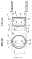
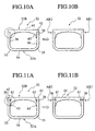
- the pipe 32 having the structure mentioned above is manufactured by assembling the first separated body 32A and the second separated body 32B (while clamping the partition plate (not shown) to a predetermined position) as shown in Fig. 8A, thereafter caulking the straight portions 36 and 36 toward the joint projections 43 and 43 of the second separated body 32B so as to temporarily fix (refer to Figs. 11A and 11B), and brazing in this state. More specifically, the heat exchanger is manufactured by integrally fixing the temporarily fixed pipe 32 according to the brazing, in a state in which the pipe 32 is assembled with the joint block, the closing member, the tube, the fin, the side plate and the like.
- a length d2 of the base end portion of the joint projections 43 and 43 of the second separated body 32B along a caulking direction is larger than a length d1 of the straight portion 36 of the second separated body 32A as shown in Fig. 7B. Accordingly, even in the case that the caulking force is applied, the joint projection 43 is prevented from being deformed.
- the first separated body 32A is set to the C-shaped cross sectional shape as shown in Fig. 8A, an insertion depth of the tube 30 can be made shallow in comparison with the header tanks 11 and 12 employing the conventional pipe 15 having the circular cross sectional shape. Accordingly, it is possible to make the structure compact in a longitudinal direction X of the tube 30 while securing the same passage cross sectional area as that of the conventional pipe 15 having the circular cross sectional shape.
- a relation L1 > L2 and S1 ⁇ S2 is satisfied.
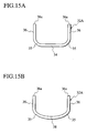
- a curved tube holding wall portion 58 may be employed as far as a curvature is larger than a curvature of the small-diameter curved portion 35 as shown in Fig. 15B.
- Fig. 15A shows the first separated body 32A according to the embodiment mentioned above for the purpose of comparing with Fig. 15B.
- the second separated body 32B of the header tank 31 is comprised of the abutment portions 42 which are provided in both ends of the main body portion 41 and with which the leading end surface 36a of the straight portion 36 of the first separated body 32A is brought into contact, and the joint projection 43 which is protruded from the inner peripheral surface 41a of the main body portion 41 and is bonded to the inner peripheral surface 36b in the leading end portion of the straight portion 36. Accordingly, it is possible to assemble the first separated body 32A and the second separated body 32B while preventing both end portions 42 and 42 of the second separated body 32B from protruding out in the width direction Y of the tube 30 from the straight portion 36 of the first separated body 32A, as shown in Figs. 9A and 9B. Accordingly, in comparison with the conventional structure in which the joint projection 21 as shown in Fig. 9B is provided in the outer side, the header tank 31 (the pipe 32) can be made compact in the width direction Y of the tube 30.
- the durability of the header tank 31 is further improved.
- the abutment portion 42 and the leading end surface 36a of the straight portion 36 are apart from each other.
- the main body portion 41 of the second separated body 32B is formed in a linear shape, it is possible to make the header tank 31 (the pipe 32) more compact along the longitudinal direction X of the tube 30.
- first separated body 32A and the second separated body 32B are temporarily fixed to each other by the caulking work of the straight portion 36 in the first separated body 32A, a jig for temporarily fixing the first separated body 32A and the second separated body 32B is not required at a time of brazing, and a wasteful heat capacity is not dissipated.
- the base end portions of the joint projections 43 and 43 in the second separated body 32B are formed thicker than the straight portion 36 of the first separated body 32A along the caulking direction Y, the joint projections 43 and 43 in the second separated body 32B do not fall down due to the caulking force, and it is possible to temporarily fix the first separated body 32A and the second separated body 32B securely.
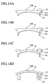
- Figs. 14A to 14D show a modified embodiment of the second separated body 32B.
- joint projections 51 and 51 may be provided as shown in Fig. 14B.
- a main body portion 52 may be formed in a curved shape as shown in Fig. 14C.
- a main body portion 54, an abutment portion 55 and a joint projection 56 may be formed by press molding one sheet of flat member as shown in Fig. 14D in place of extrusion molding the second separated body 32B.
- Fig. 14A shows the second separated body 32B according to the embodiment mentioned above for comparison.
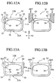
- a caulking structure shown in Figs. 11A and 11B is structured by arranging a groove 61 in base end portions of the joint projections 43 and 43 in the second separated body 32B and caulking the leading end portion of the straight portion 36 into the groove 61 by applying a caulking force in the directions of the arrows AR1 and AR2.
- the leading end portion of the straight portion 36 is locked within the groove 61 of the joint projection 43, the temporary fixing between the first separated body 32A and the second separated body 32B is more securely achieved.
- the structure may be made such that the leading end portion of the straight portion 36 is caulked to an inner side by setting the main body portion 41 (the abutment portion 42) of the second separated body 32B to be short in the width direction Y of the tube so as to operate a caulking punch 63 toward the longitudinal direction X of the tube (toward a direction of an arrow AR3 in Fig. 12B).
- protruding portions 64a and 64a protruded from the straight portions 36 and 36 are provided in an abutment portion 64 of the second separated body 32B.
- the first separated body 32A and the second separated body 32B can be temporarily fixed by applying an operating force to the protruding portions 64a and 64a in a direction of an arrow AR4 so as to fold back to the outer peripheral surface of the straight portions 36 and 36.
- the first separated body 32A and the second separated body 32B can be temporarily fixed more securely than the conventional structure.
- the protruding portions 64a and 64a are arranged in an outer side of the straight portions 36 and 36, a space efficiency is lowered in comparison with the structure in which it is unnecessary that the portion protruding to the outer side over the straight portion 36 as shown in Figs. 11A and 12A is provided.
- the pipe of the header tank is formed by combining two separated bodies which are separated along the longitudinal direction, wherein the first separated body has the tube holding wall portion including the insertion hole inserting and holding the flat tube, and wherein a pair of straight portions protruded from the tube holding wall portion in the approximately orthogonal direction and formed along both sides of the tube in the width direction, and is formed in the C-shaped cross sectional shape.
- the present invention can be applied to various structures such as a heat radiator, a condenser, an evaporator and the like as far as it is a heat exchanger. However, it is particularly effective to apply to the condenser in which the width of the header tank becomes larger than the heat exchanging portion (the core portion) constituted by the tube and the fin as shown in Fig. 1.
Landscapes
- Engineering & Computer Science (AREA)
- Physics & Mathematics (AREA)
- Thermal Sciences (AREA)
- Mechanical Engineering (AREA)
- General Engineering & Computer Science (AREA)
- Heat-Exchange Devices With Radiators And Conduit Assemblies (AREA)
- Air-Conditioning For Vehicles (AREA)
- Details Of Heat-Exchange And Heat-Transfer (AREA)
Abstract
Description
Claims (9)
- A header tank (31) for a heat exchanger in which a plurality of flat tubes (30) are communicated and connected to at least a pair of header tanks (31, 31) so as to form a multiple stages, comprising:wherein the holding wall portion and the pair of straight portions are formed in a C-shaped cross sectional shape.a pipe (32) formed by combining a first separated body (32A) and a second separated body (32B);a closing member for closing opening portions in both ends of the pipe (32);a tube holding wall portion (34) provided in the second separated body (32A) and holds the flat tube (30); anda pair of straight portions (36, 36) protruded from the tube holding wall portion (34) in an approximately orthogonal direction and formed along both ends in a width direction of the tube (30),
- A header tank for a heat exchanger according to claim 1, wherein the tube holding wall portion (34) of the first separated body (32A) is formed in a flat shape which is orthogonal to a longitudinal direction of the tube (30).
- A header tank for a heat exchanger according to claim 1 or 2, wherein the second separated body (32B) further comprises a main body portion (41) closing an opening portion (O) of the first separated body (32A), abutment portions (42, 42) provided in both ends of the main body portion (41) and abutted on the leading end surface (36a) of the straight portion (36) in the first separated body (32A), and joint projections (43, 43) protruded from the main body portion (41) and bonded to the inner peripheral surface (36a) of the leading end portion in the straight portion (36).
- A header tank for a heat exchanger according to claim 3, wherein the main body portion (41) of the second separated body (32B) is formed by connecting the abutment portions (42, 42) to each other in an approximately linear shape so as to be approximately orthogonal to the longitudinal direction of the tube (30).
- A header tank for a heat exchanger according to claim 4, wherein the inner peripheral surface (41a) of the main body portion (41) in the second separated body (32B) is formed in a circular curved surface connecting the pair of joint projections (43, 43) to each other.
- A header tank for a heat exchanger according to any one of claims 3 to 5, wherein the first and second separated bodies (32A, 32B) are fixed with brazing in a state of being temporarily fixed to each other, by combining the first separated body (32A) with the second separated body (32B), and thereafter caulking a pair of opposing straight portions (36, 36) of the first separated body (32A) toward the joint projections (43, 43) of the second separated body (32B).
- A header tank for a heat exchanger according to claim 6, wherein at least base end portions of the joint projections (43, 43) in the second separated body (32B) are formed thicker than the straight portions (36, 36) of the first separated body (32A) along the caulking direction.
- A header tank for a heat exchanger according to claim 6 or 7, wherein a groove (61) is provided in the base end portion of the joint projection (43) in the second separated body (32B), and the leading end portions of the straight portions (36, 36) are caulked into the groove (61).
- A header tank for a heat exchanger according to any one of claims 3 to 5, wherein the abutment portions (64, 64) of the second separated body (32B) have protruding portions (64a, 64a) protruding over the straight portions (36, 36), and the first separated body (32A) and the second separated body (32B) are temporarily fixed by folding back the protruding portions (64a, 64a) to an outer surface side of the straight portions (36, 36).
Applications Claiming Priority (2)
| Application Number | Priority Date | Filing Date | Title |
|---|---|---|---|
| JP2003096895 | 2003-03-31 | ||
| JP2003096895A JP2004301454A (en) | 2003-03-31 | 2003-03-31 | Header tank for heat exchanger |
Publications (2)
| Publication Number | Publication Date |
|---|---|
| EP1471323A2 true EP1471323A2 (en) | 2004-10-27 |
| EP1471323A3 EP1471323A3 (en) | 2005-09-21 |
Family
ID=32959550
Family Applications (1)
| Application Number | Title | Priority Date | Filing Date |
|---|---|---|---|
| EP04007871A Withdrawn EP1471323A3 (en) | 2003-03-31 | 2004-03-31 | Header tank for heat exchanger |
Country Status (4)
| Country | Link |
|---|---|
| US (1) | US7201218B2 (en) |
| EP (1) | EP1471323A3 (en) |
| JP (1) | JP2004301454A (en) |
| CN (1) | CN1318816C (en) |
Cited By (2)
| Publication number | Priority date | Publication date | Assignee | Title |
|---|---|---|---|---|
| EP1809968A4 (en) * | 2004-11-12 | 2011-04-20 | Carrier Corp | Parallel flow evaporator with shaped manifolds |
| EP3086074A1 (en) * | 2015-04-23 | 2016-10-26 | MAHLE International GmbH | Tubular element and heat exchanger |
Families Citing this family (23)
| Publication number | Priority date | Publication date | Assignee | Title |
|---|---|---|---|---|
| AT506309B1 (en) * | 2008-06-03 | 2009-08-15 | Pustelnik Philipp Dipl Ing | PLATE COOLER FOR LIQUIDS |
| FR2968389B1 (en) * | 2010-12-07 | 2015-03-06 | Valeo Systemes Thermiques | COLLECTOR BOX FOR HEAT EXCHANGER AND CORRESPONDING HEAT EXCHANGER |
| FR2973492B1 (en) * | 2011-03-31 | 2017-12-15 | Valeo Systemes Thermiques | COLLECTOR BOX FOR A HEAT EXCHANGER, IN PARTICULAR FOR A MOTOR VEHICLE, AND THERMAL EXCHANGER THEREFOR |
| WO2013160956A1 (en) * | 2012-04-26 | 2013-10-31 | 三菱電機株式会社 | Heat-exchanger header and heat exchanger provided therewith |
| DE102012210339A1 (en) * | 2012-06-19 | 2013-12-19 | Behr Gmbh & Co. Kg | Heat exchanger |
| WO2014091536A1 (en) * | 2012-12-10 | 2014-06-19 | 三菱電機株式会社 | Flat tube heat exchange apparatus |
| FR3015016B1 (en) * | 2013-12-13 | 2019-05-17 | Valeo Systemes Thermiques | COLLECTOR BOX AND THERMAL EXCHANGER CORRESPONDING |
| US9630281B2 (en) * | 2014-01-31 | 2017-04-25 | Mahle International Gmbh | Flux shield for heat exchanger |
| DE102014219387A1 (en) * | 2014-09-25 | 2016-03-31 | Mahle International Gmbh | Collector and associated heat exchanger |
| JP6583071B2 (en) * | 2015-03-20 | 2019-10-02 | 株式会社デンソー | Tank and heat exchanger |
| US10032693B2 (en) * | 2015-10-20 | 2018-07-24 | General Electric Company | Heat transfer chassis and method for forming the same |
| CN105823347A (en) * | 2016-05-12 | 2016-08-03 | 珠海格力电器股份有限公司 | Water heater and heat exchanger assembly thereof |
| CN106091789A (en) * | 2016-06-17 | 2016-11-09 | 安徽天祥空调科技有限公司 | A kind of full aluminum liquid accumulating device on radiator and moulding process thereof |
| CN106150667A (en) * | 2016-08-31 | 2016-11-23 | 山东同创汽车散热装置股份有限公司 | One body swimming chamber device and radiator and the production method of one body swimming chamber device |
| JP6790948B2 (en) * | 2017-03-21 | 2020-11-25 | 株式会社デンソー | Heat exchanger |
| WO2019078066A1 (en) * | 2017-10-18 | 2019-04-25 | ダイキン工業株式会社 | Heat exchanger and air conditioning device with same |
| US10890386B2 (en) * | 2019-02-01 | 2021-01-12 | Mahle International Gmbh | Evaporator unit including distributor tube and method thereof |
| DE112020006927T5 (en) * | 2020-03-19 | 2023-01-12 | Mitsubishi Electric Corporation | Heat exchanger manifold, heat exchanger, method of making a heat exchanger manifold, and method of making a heat exchanger |
| CN112444050A (en) * | 2020-11-30 | 2021-03-05 | 东莞汉旭五金塑胶科技有限公司 | Integral cavity type water cooling drainage with built-in water pump |
| CN112393626B (en) | 2020-12-09 | 2025-03-11 | 惠州汉旭五金塑胶科技有限公司 | Liquid cooling water discharge with multiple water inlet channels, multiple water collection boxes and water pumps |
| JP2022134914A (en) * | 2021-03-04 | 2022-09-15 | 株式会社デンソー | Heat exchanger |
| JP7146139B1 (en) * | 2021-04-06 | 2022-10-03 | 三菱電機株式会社 | heat exchangers and air conditioners |
| JPWO2024135191A1 (en) * | 2022-12-23 | 2024-06-27 |
Family Cites Families (16)
| Publication number | Priority date | Publication date | Assignee | Title |
|---|---|---|---|---|
| US5152339A (en) * | 1990-04-03 | 1992-10-06 | Thermal Components, Inc. | Manifold assembly for a parallel flow heat exchanger |
| JP2801373B2 (en) * | 1990-07-02 | 1998-09-21 | サンデン株式会社 | Heat exchanger |
| JP2968063B2 (en) * | 1991-02-20 | 1999-10-25 | サンデン株式会社 | Heat exchanger |
| DE4137037A1 (en) * | 1991-07-02 | 1993-01-14 | Thermal Waerme Kaelte Klima | COLLECTOR FOR A FLAT TUBE CONDENSER |
| JP2774237B2 (en) | 1993-10-06 | 1998-07-09 | 株式会社 マルナカ | Pipe for refrigerant condenser |
| US5450896A (en) * | 1994-01-25 | 1995-09-19 | Wynn's Climate Systems, Inc. | Two-piece header |
| JP3353475B2 (en) * | 1994-07-28 | 2002-12-03 | 株式会社デンソー | Heat exchanger |
| SE503085C2 (en) * | 1995-01-25 | 1996-03-25 | Valeo Engine Cooling Ab | Heat exchanger tank with end pieces, method of making such a tank, and heat exchanger provided with such |
| SE516092C2 (en) * | 1995-01-25 | 2001-11-19 | Valeo Engine Cooling Ab | Heat exchanger tank for mounting in an oil cooler, process for making such a tank, and heat exchanger |
| EP0913404B1 (en) * | 1996-07-16 | 2006-06-14 | Asahi Kasei Kabushiki Kaisha | Differentiation inhibitor |
| JP3760571B2 (en) * | 1997-06-24 | 2006-03-29 | 株式会社デンソー | Heat exchanger |
| US6062303A (en) * | 1997-09-26 | 2000-05-16 | Halla Climate Control Corp. | Multiflow type condenser for an air conditioner |
| JP2000304488A (en) * | 1999-04-23 | 2000-11-02 | Calsonic Kansei Corp | Aluminum alloy heat exchanger |
| JP2001194088A (en) | 1999-10-19 | 2001-07-17 | Zexel Valeo Climate Control Corp | Heat exchanger |
| US20010048930A1 (en) * | 1999-12-15 | 2001-12-06 | Lamb Jonathan Robert | Methods of immunosuppression |
| JP2002318093A (en) | 2001-04-16 | 2002-10-31 | Zexel Valeo Climate Control Corp | Heat exchanger |
-
2003
- 2003-03-31 JP JP2003096895A patent/JP2004301454A/en active Pending
-
2004
- 2004-03-24 US US10/807,722 patent/US7201218B2/en not_active Expired - Fee Related
- 2004-03-31 CN CNB2004100316496A patent/CN1318816C/en not_active Expired - Fee Related
- 2004-03-31 EP EP04007871A patent/EP1471323A3/en not_active Withdrawn
Cited By (2)
| Publication number | Priority date | Publication date | Assignee | Title |
|---|---|---|---|---|
| EP1809968A4 (en) * | 2004-11-12 | 2011-04-20 | Carrier Corp | Parallel flow evaporator with shaped manifolds |
| EP3086074A1 (en) * | 2015-04-23 | 2016-10-26 | MAHLE International GmbH | Tubular element and heat exchanger |
Also Published As
| Publication number | Publication date |
|---|---|
| EP1471323A3 (en) | 2005-09-21 |
| US20040226705A1 (en) | 2004-11-18 |
| CN1534267A (en) | 2004-10-06 |
| US7201218B2 (en) | 2007-04-10 |
| JP2004301454A (en) | 2004-10-28 |
| CN1318816C (en) | 2007-05-30 |
Similar Documents
| Publication | Publication Date | Title |
|---|---|---|
| US7201218B2 (en) | Header tank for heat exchanger | |
| US5586598A (en) | Heat exchanger | |
| US20050011637A1 (en) | Heat exchanger and tube for heat exchanger | |
| US7140425B2 (en) | Plate-tube type heat exchanger | |
| US6293011B1 (en) | Heat exchanger for vehicle air conditioner | |
| JPH1114288A (en) | Heat exchanger | |
| US20040182558A1 (en) | Header for use in heat exchanger, heat exchanger and method for manufacturing the same | |
| US6173765B1 (en) | Heat exchange having header tank | |
| JP2011099664A (en) | Heat exchanger | |
| US6691772B2 (en) | Heat exchanger | |
| JP2002228387A (en) | Heat exchanger | |
| JP2004301455A (en) | Header tank for heat exchanger | |
| AU2002320794B2 (en) | Heat exchanger | |
| JPH0587483A (en) | Aluminum heat exchanger | |
| JP3894079B2 (en) | Connection structure of heat exchanger header and piping | |
| JP2980445B2 (en) | Heat exchanger | |
| JP4081883B2 (en) | Heat exchanger | |
| JP2578558B2 (en) | Heat exchanger | |
| JP4418246B2 (en) | Heat exchanger | |
| KR200234727Y1 (en) | Condenser assembly for air-conditioner oh vehicle | |
| JPH08219680A (en) | Heat-exchanger | |
| JPH10122771A (en) | Stacked heat exchanger | |
| JP2004271101A (en) | Heat exchanger with liquid receiver | |
| JPH04363591A (en) | Heat exchanger | |
| JPH10339586A (en) | Heat exchanger |
Legal Events
| Date | Code | Title | Description |
|---|---|---|---|
| PUAI | Public reference made under article 153(3) epc to a published international application that has entered the european phase |
Free format text: ORIGINAL CODE: 0009012 |
|
| AK | Designated contracting states |
Kind code of ref document: A2 Designated state(s): AT BE BG CH CY CZ DE DK EE ES FI FR GB GR HU IE IT LI LU MC NL PL PT RO SE SI SK TR |
|
| AX | Request for extension of the european patent |
Extension state: AL LT LV MK |
|
| PUAL | Search report despatched |
Free format text: ORIGINAL CODE: 0009013 |
|
| AK | Designated contracting states |
Kind code of ref document: A3 Designated state(s): AT BE BG CH CY CZ DE DK EE ES FI FR GB GR HU IE IT LI LU MC NL PL PT RO SE SI SK TR |
|
| AX | Request for extension of the european patent |
Extension state: AL LT LV MK |
|
| RIC1 | Information provided on ipc code assigned before grant |
Ipc: 7F 28D 1/053 B Ipc: 7F 28F 9/02 A |
|
| 17P | Request for examination filed |
Effective date: 20051024 |
|
| AKX | Designation fees paid |
Designated state(s): DE FR GB |
|
| 17Q | First examination report despatched |
Effective date: 20090409 |
|
| STAA | Information on the status of an ep patent application or granted ep patent |
Free format text: STATUS: THE APPLICATION IS DEEMED TO BE WITHDRAWN |
|
| 18D | Application deemed to be withdrawn |
Effective date: 20090820 |