EP1471255A1 - Pompe rotative à palettes - Google Patents
Pompe rotative à palettes Download PDFInfo
- Publication number
- EP1471255A1 EP1471255A1 EP03400016A EP03400016A EP1471255A1 EP 1471255 A1 EP1471255 A1 EP 1471255A1 EP 03400016 A EP03400016 A EP 03400016A EP 03400016 A EP03400016 A EP 03400016A EP 1471255 A1 EP1471255 A1 EP 1471255A1
- Authority
- EP
- European Patent Office
- Prior art keywords
- rotor
- wing
- insert
- pump
- pump according
- Prior art date
- Legal status (The legal status is an assumption and is not a legal conclusion. Google has not performed a legal analysis and makes no representation as to the accuracy of the status listed.)
- Granted
Links
Images

Classifications
-
- F—MECHANICAL ENGINEERING; LIGHTING; HEATING; WEAPONS; BLASTING
- F04—POSITIVE - DISPLACEMENT MACHINES FOR LIQUIDS; PUMPS FOR LIQUIDS OR ELASTIC FLUIDS
- F04C—ROTARY-PISTON, OR OSCILLATING-PISTON, POSITIVE-DISPLACEMENT MACHINES FOR LIQUIDS; ROTARY-PISTON, OR OSCILLATING-PISTON, POSITIVE-DISPLACEMENT PUMPS
- F04C15/00—Component parts, details or accessories of machines, pumps or pumping installations, not provided for in groups F04C2/00 - F04C14/00
- F04C15/0003—Sealing arrangements in rotary-piston machines or pumps
- F04C15/0007—Radial sealings for working fluid
- F04C15/0011—Radial sealings for working fluid of rigid material
-
- F—MECHANICAL ENGINEERING; LIGHTING; HEATING; WEAPONS; BLASTING
- F01—MACHINES OR ENGINES IN GENERAL; ENGINE PLANTS IN GENERAL; STEAM ENGINES
- F01C—ROTARY-PISTON OR OSCILLATING-PISTON MACHINES OR ENGINES
- F01C19/00—Sealing arrangements in rotary-piston machines or engines
- F01C19/005—Structure and composition of sealing elements such as sealing strips, sealing rings and the like; Coating of these elements
-
- F—MECHANICAL ENGINEERING; LIGHTING; HEATING; WEAPONS; BLASTING
- F01—MACHINES OR ENGINES IN GENERAL; ENGINE PLANTS IN GENERAL; STEAM ENGINES
- F01C—ROTARY-PISTON OR OSCILLATING-PISTON MACHINES OR ENGINES
- F01C21/00—Component parts, details or accessories not provided for in groups F01C1/00 - F01C20/00
- F01C21/08—Rotary pistons
- F01C21/0809—Construction of vanes or vane holders
- F01C21/0881—Construction of vanes or vane holders the vanes consisting of two or more parts
-
- F—MECHANICAL ENGINEERING; LIGHTING; HEATING; WEAPONS; BLASTING
- F04—POSITIVE - DISPLACEMENT MACHINES FOR LIQUIDS; PUMPS FOR LIQUIDS OR ELASTIC FLUIDS
- F04C—ROTARY-PISTON, OR OSCILLATING-PISTON, POSITIVE-DISPLACEMENT MACHINES FOR LIQUIDS; ROTARY-PISTON, OR OSCILLATING-PISTON, POSITIVE-DISPLACEMENT PUMPS
- F04C18/00—Rotary-piston pumps specially adapted for elastic fluids
- F04C18/30—Rotary-piston pumps specially adapted for elastic fluids having the characteristics covered by two or more of groups F04C18/02, F04C18/08, F04C18/22, F04C18/24, F04C18/48, or having the characteristics covered by one of these groups together with some other type of movement between co-operating members
- F04C18/34—Rotary-piston pumps specially adapted for elastic fluids having the characteristics covered by two or more of groups F04C18/02, F04C18/08, F04C18/22, F04C18/24, F04C18/48, or having the characteristics covered by one of these groups together with some other type of movement between co-operating members having the movement defined in group F04C18/08 or F04C18/22 and relative reciprocation between the co-operating members
- F04C18/344—Rotary-piston pumps specially adapted for elastic fluids having the characteristics covered by two or more of groups F04C18/02, F04C18/08, F04C18/22, F04C18/24, F04C18/48, or having the characteristics covered by one of these groups together with some other type of movement between co-operating members having the movement defined in group F04C18/08 or F04C18/22 and relative reciprocation between the co-operating members with vanes reciprocating with respect to the inner member
- F04C18/3441—Rotary-piston pumps specially adapted for elastic fluids having the characteristics covered by two or more of groups F04C18/02, F04C18/08, F04C18/22, F04C18/24, F04C18/48, or having the characteristics covered by one of these groups together with some other type of movement between co-operating members having the movement defined in group F04C18/08 or F04C18/22 and relative reciprocation between the co-operating members with vanes reciprocating with respect to the inner member the inner and outer member being in contact along one line or continuous surface substantially parallel to the axis of rotation
- F04C18/3442—Rotary-piston pumps specially adapted for elastic fluids having the characteristics covered by two or more of groups F04C18/02, F04C18/08, F04C18/22, F04C18/24, F04C18/48, or having the characteristics covered by one of these groups together with some other type of movement between co-operating members having the movement defined in group F04C18/08 or F04C18/22 and relative reciprocation between the co-operating members with vanes reciprocating with respect to the inner member the inner and outer member being in contact along one line or continuous surface substantially parallel to the axis of rotation the surfaces of the inner and outer member, forming the inlet and outlet opening
-
- F—MECHANICAL ENGINEERING; LIGHTING; HEATING; WEAPONS; BLASTING
- F04—POSITIVE - DISPLACEMENT MACHINES FOR LIQUIDS; PUMPS FOR LIQUIDS OR ELASTIC FLUIDS
- F04C—ROTARY-PISTON, OR OSCILLATING-PISTON, POSITIVE-DISPLACEMENT MACHINES FOR LIQUIDS; ROTARY-PISTON, OR OSCILLATING-PISTON, POSITIVE-DISPLACEMENT PUMPS
- F04C2/00—Rotary-piston machines or pumps
- F04C2/30—Rotary-piston machines or pumps having the characteristics covered by two or more groups F04C2/02, F04C2/08, F04C2/22, F04C2/24 or having the characteristics covered by one of these groups together with some other type of movement between co-operating members
- F04C2/34—Rotary-piston machines or pumps having the characteristics covered by two or more groups F04C2/02, F04C2/08, F04C2/22, F04C2/24 or having the characteristics covered by one of these groups together with some other type of movement between co-operating members having the movement defined in groups F04C2/08 or F04C2/22 and relative reciprocation between the co-operating members
- F04C2/344—Rotary-piston machines or pumps having the characteristics covered by two or more groups F04C2/02, F04C2/08, F04C2/22, F04C2/24 or having the characteristics covered by one of these groups together with some other type of movement between co-operating members having the movement defined in groups F04C2/08 or F04C2/22 and relative reciprocation between the co-operating members with vanes reciprocating with respect to the inner member
- F04C2/3441—Rotary-piston machines or pumps having the characteristics covered by two or more groups F04C2/02, F04C2/08, F04C2/22, F04C2/24 or having the characteristics covered by one of these groups together with some other type of movement between co-operating members having the movement defined in groups F04C2/08 or F04C2/22 and relative reciprocation between the co-operating members with vanes reciprocating with respect to the inner member the inner and outer member being in contact along one line or continuous surface substantially parallel to the axis of rotation
- F04C2/3442—Rotary-piston machines or pumps having the characteristics covered by two or more groups F04C2/02, F04C2/08, F04C2/22, F04C2/24 or having the characteristics covered by one of these groups together with some other type of movement between co-operating members having the movement defined in groups F04C2/08 or F04C2/22 and relative reciprocation between the co-operating members with vanes reciprocating with respect to the inner member the inner and outer member being in contact along one line or continuous surface substantially parallel to the axis of rotation the surfaces of the inner and outer member, forming the working space, being surfaces of revolution
-
- F—MECHANICAL ENGINEERING; LIGHTING; HEATING; WEAPONS; BLASTING
- F04—POSITIVE - DISPLACEMENT MACHINES FOR LIQUIDS; PUMPS FOR LIQUIDS OR ELASTIC FLUIDS
- F04C—ROTARY-PISTON, OR OSCILLATING-PISTON, POSITIVE-DISPLACEMENT MACHINES FOR LIQUIDS; ROTARY-PISTON, OR OSCILLATING-PISTON, POSITIVE-DISPLACEMENT PUMPS
- F04C2230/00—Manufacture
- F04C2230/20—Manufacture essentially without removing material
- F04C2230/22—Manufacture essentially without removing material by sintering
-
- F—MECHANICAL ENGINEERING; LIGHTING; HEATING; WEAPONS; BLASTING
- F05—INDEXING SCHEMES RELATING TO ENGINES OR PUMPS IN VARIOUS SUBCLASSES OF CLASSES F01-F04
- F05C—INDEXING SCHEME RELATING TO MATERIALS, MATERIAL PROPERTIES OR MATERIAL CHARACTERISTICS FOR MACHINES, ENGINES OR PUMPS OTHER THAN NON-POSITIVE-DISPLACEMENT MACHINES OR ENGINES
- F05C2225/00—Synthetic polymers, e.g. plastics; Rubber
- F05C2225/10—Polyimides, e.g. Aurum
-
- F—MECHANICAL ENGINEERING; LIGHTING; HEATING; WEAPONS; BLASTING
- F05—INDEXING SCHEMES RELATING TO ENGINES OR PUMPS IN VARIOUS SUBCLASSES OF CLASSES F01-F04
- F05C—INDEXING SCHEME RELATING TO MATERIALS, MATERIAL PROPERTIES OR MATERIAL CHARACTERISTICS FOR MACHINES, ENGINES OR PUMPS OTHER THAN NON-POSITIVE-DISPLACEMENT MACHINES OR ENGINES
- F05C2225/00—Synthetic polymers, e.g. plastics; Rubber
- F05C2225/12—Polyetheretherketones, e.g. PEEK
Definitions
- the invention relates to a rotor pump with a pump housing with a pump room, one rotatably mounted in the pump room Rotor, a wing that is slidably mounted in the rotor and that supports the Pump room divided into two chambers and at the Inner circumferential wall of the pump chamber bears, so that the wing with respect to the rotor and with respect to the inner peripheral wall Relative movement executes.
- a positive displacement pump is known from DE-A-100 12 406 become a rotor within a housing space is rotatably mounted, a wing in a groove slidably picks up. Both the rotor and the wing are made of plastic which has the advantage of being low dynamic forces occur.
- This task is the rotor pump of the aforementioned Art solved according to the invention in that at least part of the components carrying out relative movements with one another an insert forming a bearing is provided.
- the rotor pump according to the invention where at the points Relative movements occur built-in insert provides the significant advantage that the Frictional forces can be reduced and therefore not only the Wear but also the warming can be reduced.
- the wing can be guided more precisely because the Insert also serves as a guide.
- the rotor points a wing receiving groove
- the groove is partially occupied with the insert.
- the insert can also be provided on the wing, so that this is moved with the wing.
- the insert is preferred however in the groove, so that the insert does not match the Wing oscillates.
- the wing in Area of its wing edge lying against the inner peripheral wall is provided with the insert. This edge forms the Contact surfaces of the wing, which also causes the seal becomes.
- the edge can be in the longitudinal direction of the wing be slidably mounted in an open groove.
- plastic polyether ether ketone (PEEK), polyether sulfide (PES), syndiotactic polystyrene (SPS), polyvinyl sulfide (PPS) or polyimide are used.
- the insert is injected. This has the main advantage that the individual components can be manufactured quickly and inexpensively can and that the deposits are captive in the respective Component are held.
- the insert is positively attached.
- this can be done using a Dovetail connection done, or the deposits can also only be inserted in corresponding interpretations and are carried out by the adjacent, a relative movement Component secured against falling out.
- the insert essentially has one rectangular or plate-like shape. This allows the insoles are manufactured inexpensively without them certain forms of the rotor, the wing or the like need to be adjusted. Especially with sintered materials this shape is an advantage.
- the insert is preferably made of metal, ceramic, from one Sintered material or made of a plastic, the Hardness of the plastic is greater than the hardness of the wing, Rotors or the material of the inner peripheral wall.
- the wing tip and for the inner peripheral wall hard materials are used to Example metal.
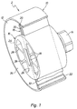
- FIG. 1 shows a rotor pump, designated overall by 2, which, in a known manner, a pump housing 10, one in its e.g. Circular cylindrical pump chamber 12 can be rotated eccentrically mounted rotor 16, the drive shaft 14 rotatably is connected, and a radially displaceable in this mounted wing 18, one at its wing ends Insert 20 and 22 has.
- a pump housing 10 one in its e.g. Circular cylindrical pump chamber 12 can be rotated eccentrically mounted rotor 16
- the drive shaft 14 rotatably is connected
- a radially displaceable in this mounted wing 18, one at its wing ends Insert 20 and 22 has.
- the rotor 18 has a hollow cylindrical rotor jacket 24, in which one extends along its inner diameter extending inner wing guide strip 26 is provided, in which the wing 18 is received in a radially displaceable manner.
- the Reference numerals 28 denote inner rotor bars which are used for Serve stiffening of the rotor shell 24.
- the rotor 16 is like shown in Figure 4, to the drive shaft 14 towards the receptacle of the wing 18 slotted and on the drive shaft 14th attached, inserted or molded.
- the pump chamber 12 is what is not shown for the sake of simplicity is tightly sealed on both ends, the Drive shaft 14 which is a liquid-tight housing end wall interspersed. At the pump chamber 12 are also an inflow and a drain line connected to a to be promoted Fluid to and from the rotor pump 2 again to be able to dissipate.
- the inserts 20 and 22 of the wing 18 are strip-like formed and in each case to the free ends of the wing 18th open grooves 30 and 32 received radially displaceable. Another embodiment provides that the inserts 20 and 22 are injected into the wing 18 and therefore rigid with are connected to this.
- the Wing 18 divided into two and consists of two wing halves during operation of the rotor pump 2 due to centrifugal force push outside.
- the inserts 20 and 22 slide on the Inner peripheral wall 34 of the pump chamber 12.
- the vane 18 is in the rotor 6 in a guide groove 36 in mounted radially and leads with respect the inner wall of the guide groove 36 relative movements.
- the Inner wall of the guide groove 36 is made of deposits 38 and 40 formed, which rest on the flat sides of the wing 18.
- the Deposits 38 and 40 extend the entire length of the Guide groove 36, which is clearly shown in Figure 2. There are also the two inserted in the grooves 30 and 32 Deposits 22 of the wing 18 can be seen.
- the inserts 38 and 40 are injected into the rotor 18 and have a tongue and groove connection in the axial direction of the rotor 18, which is designated by 42, which is shown in FIG. 3 is recognizable.
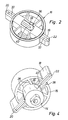
- Figure 4 shows the back of the rotor 16, to which the Drive shaft 14 is molded and the guide groove 36th closes on the drive side.
- Inserts 20 and 22 as well as 38 and 40 are recognizable, which are on wing 18 abut or with which the wing 18 on the Inner peripheral wall 34 of the pump chamber 12 abuts.
- the deposits 20 and 22 and 38 and 40 each form a bearing for the adjacent components that perform relative movements.
Landscapes
- Engineering & Computer Science (AREA)
- Mechanical Engineering (AREA)
- General Engineering & Computer Science (AREA)
- Details And Applications Of Rotary Liquid Pumps (AREA)
- Rotary Pumps (AREA)
Priority Applications (2)
| Application Number | Priority Date | Filing Date | Title |
|---|---|---|---|
| EP20030400016 EP1471255B1 (fr) | 2003-04-24 | 2003-04-24 | Pompe rotative à palettes |
| DE50300812T DE50300812D1 (de) | 2003-04-24 | 2003-04-24 | Flügelzellenpumpe |
Applications Claiming Priority (1)
| Application Number | Priority Date | Filing Date | Title |
|---|---|---|---|
| EP20030400016 EP1471255B1 (fr) | 2003-04-24 | 2003-04-24 | Pompe rotative à palettes |
Publications (2)
| Publication Number | Publication Date |
|---|---|
| EP1471255A1 true EP1471255A1 (fr) | 2004-10-27 |
| EP1471255B1 EP1471255B1 (fr) | 2005-07-20 |
Family
ID=32946973
Family Applications (1)
| Application Number | Title | Priority Date | Filing Date |
|---|---|---|---|
| EP20030400016 Expired - Lifetime EP1471255B1 (fr) | 2003-04-24 | 2003-04-24 | Pompe rotative à palettes |
Country Status (2)
| Country | Link |
|---|---|
| EP (1) | EP1471255B1 (fr) |
| DE (1) | DE50300812D1 (fr) |
Cited By (10)
| Publication number | Priority date | Publication date | Assignee | Title |
|---|---|---|---|---|
| WO2006048055A1 (fr) * | 2004-10-29 | 2006-05-11 | Joma-Hydromechanic Gmbh | Ailette pour pompe a rotor |
| EP1707816A1 (fr) | 2005-03-31 | 2006-10-04 | Joma-Hydromechanic GmbH | Pompe de vide |
| DE102005031589A1 (de) * | 2005-07-06 | 2007-01-11 | Schaeffler Kg | Wasserpumpenflügelrad |
| WO2007042135A1 (fr) * | 2005-10-13 | 2007-04-19 | Joma-Hydromechanic Gmbh | Pompe a rotor |
| WO2007042134A1 (fr) | 2005-10-13 | 2007-04-19 | Joma-Hydromechanic Gmbh | Pompe a rotor et ailette pour pompe a rotor |
| WO2007054162A1 (fr) * | 2005-11-14 | 2007-05-18 | Joma-Hydromechanic Gmbh | Pompe a rotor |
| WO2007054163A1 (fr) * | 2005-11-14 | 2007-05-18 | Joma-Hydromechanic Gmbh | Pompe a vide |
| WO2007054155A1 (fr) | 2005-11-14 | 2007-05-18 | Joma-Hydromechanic Gmbh | Pompe a vide |
| DE102006016244A1 (de) * | 2006-03-31 | 2007-10-04 | Joma-Hydromechanic Gmbh | Rotorpumpe |
| WO2007115782A1 (fr) * | 2006-04-11 | 2007-10-18 | Vhit S.P.A. | Rotor pour pompe a palettes, fait de materiau plastique renforce par une feuille metallique |
Families Citing this family (1)
| Publication number | Priority date | Publication date | Assignee | Title |
|---|---|---|---|---|
| DE102006034758B4 (de) * | 2006-07-24 | 2011-03-31 | Joma-Polytec Gmbh | Rotorpumpe |
Citations (7)
| Publication number | Priority date | Publication date | Assignee | Title |
|---|---|---|---|---|
| US2410596A (en) * | 1943-11-09 | 1946-11-05 | Aaron C Bradford | Sliding vane engine or pump |
| US2679973A (en) * | 1951-06-08 | 1954-06-01 | John W Berg | Materials moving apparatus |
| US2903971A (en) * | 1957-05-27 | 1959-09-15 | Lowell J Collins | Pumps |
| FR2175295A5 (fr) * | 1972-03-08 | 1973-10-19 | Reich Fa Wilhelm | |
| EP1113175A1 (fr) * | 1998-09-08 | 2001-07-04 | Ebara Corporation | Machine rotative a aubes |
| EP1134417A2 (fr) * | 2000-03-15 | 2001-09-19 | Joma-Hydromechanic GmbH | Pompe à déplacement positif |
| WO2002025113A1 (fr) * | 2000-09-21 | 2002-03-28 | Robert Bosch Gmbh | Ailette en plastique pour pompe a vide a cellule en ailette |
-
2003
- 2003-04-24 EP EP20030400016 patent/EP1471255B1/fr not_active Expired - Lifetime
- 2003-04-24 DE DE50300812T patent/DE50300812D1/de not_active Expired - Lifetime
Patent Citations (7)
| Publication number | Priority date | Publication date | Assignee | Title |
|---|---|---|---|---|
| US2410596A (en) * | 1943-11-09 | 1946-11-05 | Aaron C Bradford | Sliding vane engine or pump |
| US2679973A (en) * | 1951-06-08 | 1954-06-01 | John W Berg | Materials moving apparatus |
| US2903971A (en) * | 1957-05-27 | 1959-09-15 | Lowell J Collins | Pumps |
| FR2175295A5 (fr) * | 1972-03-08 | 1973-10-19 | Reich Fa Wilhelm | |
| EP1113175A1 (fr) * | 1998-09-08 | 2001-07-04 | Ebara Corporation | Machine rotative a aubes |
| EP1134417A2 (fr) * | 2000-03-15 | 2001-09-19 | Joma-Hydromechanic GmbH | Pompe à déplacement positif |
| WO2002025113A1 (fr) * | 2000-09-21 | 2002-03-28 | Robert Bosch Gmbh | Ailette en plastique pour pompe a vide a cellule en ailette |
Cited By (13)
| Publication number | Priority date | Publication date | Assignee | Title |
|---|---|---|---|---|
| WO2006048055A1 (fr) * | 2004-10-29 | 2006-05-11 | Joma-Hydromechanic Gmbh | Ailette pour pompe a rotor |
| DE102004053521A1 (de) * | 2004-10-29 | 2006-05-11 | Joma-Hydromechanic Gmbh | Flügel für eine Rotorpumpe |
| EP1707816A1 (fr) | 2005-03-31 | 2006-10-04 | Joma-Hydromechanic GmbH | Pompe de vide |
| DE102005015721B3 (de) * | 2005-03-31 | 2006-12-21 | Joma-Hydromechanic Gmbh | Vakuumpumpe |
| DE102005031589A1 (de) * | 2005-07-06 | 2007-01-11 | Schaeffler Kg | Wasserpumpenflügelrad |
| WO2007042135A1 (fr) * | 2005-10-13 | 2007-04-19 | Joma-Hydromechanic Gmbh | Pompe a rotor |
| WO2007042134A1 (fr) | 2005-10-13 | 2007-04-19 | Joma-Hydromechanic Gmbh | Pompe a rotor et ailette pour pompe a rotor |
| WO2007054162A1 (fr) * | 2005-11-14 | 2007-05-18 | Joma-Hydromechanic Gmbh | Pompe a rotor |
| WO2007054163A1 (fr) * | 2005-11-14 | 2007-05-18 | Joma-Hydromechanic Gmbh | Pompe a vide |
| WO2007054155A1 (fr) | 2005-11-14 | 2007-05-18 | Joma-Hydromechanic Gmbh | Pompe a vide |
| DE102006016244A1 (de) * | 2006-03-31 | 2007-10-04 | Joma-Hydromechanic Gmbh | Rotorpumpe |
| WO2007115782A1 (fr) * | 2006-04-11 | 2007-10-18 | Vhit S.P.A. | Rotor pour pompe a palettes, fait de materiau plastique renforce par une feuille metallique |
| US8246332B2 (en) | 2006-04-11 | 2012-08-21 | Vhit S.P.A. | Rotor for a vane pump, made of plastic material reinforced by metallic foil |
Also Published As
| Publication number | Publication date |
|---|---|
| EP1471255B1 (fr) | 2005-07-20 |
| DE50300812D1 (de) | 2005-08-25 |
Similar Documents
| Publication | Publication Date | Title |
|---|---|---|
| EP2929191B1 (fr) | Pompe centrifuge, en particulier pour eaux usées ou eaux grasses | |
| DE69911013T2 (de) | Impellerpumpe mit flexiblen flügeln | |
| EP1977084B1 (fr) | Dispositif de direction pouvant etre deplace | |
| EP1471255B1 (fr) | Pompe rotative à palettes | |
| EP1766237B1 (fr) | Pompe a vide a une ailette | |
| EP1327778A2 (fr) | Pompe à palette | |
| EP1952027B1 (fr) | Pompe à rotor | |
| DE3740419A1 (de) | Fluegelzellenpumpe | |
| DE102011078017B3 (de) | Pumpe | |
| EP1707816B1 (fr) | Pompe de vide | |
| DE3119605A1 (de) | Raeumvorrichtung | |
| EP1766238B1 (fr) | Pompe a vide a une ailette | |
| EP2795100A1 (fr) | Vis sans fin pour déplacer des liquides et dispositif pour faire fonctionner une vis sans fin pour déplacer des liquides | |
| DE3738943A1 (de) | Fluegelzellenpumpe | |
| DE3528963C2 (fr) | ||
| DE102004041254A1 (de) | Verfahren und Vorrichtung zur Kompensation der thermischen Ausdehnung eines Zellenradschleusenrotors | |
| EP1805396B1 (fr) | Pompe rotative avec une palette | |
| EP2002084B1 (fr) | Pompe à rotor et ailette destinée à une pompe à rotor | |
| DE102005018732B3 (de) | Scheibenverdichter mit Verteilerstern | |
| EP0339332A2 (fr) | Pompe à palettes pour le transport de produits alimentaires | |
| DE3738484C2 (fr) | ||
| DE3812794A1 (de) | Rotationspumpe | |
| DE102005058129A1 (de) | Vakuumpumpe | |
| EP3913187B1 (fr) | Pompe à vis | |
| DE2654991A1 (de) | Drehschieberkompressor |
Legal Events
| Date | Code | Title | Description |
|---|---|---|---|
| PUAI | Public reference made under article 153(3) epc to a published international application that has entered the european phase |
Free format text: ORIGINAL CODE: 0009012 |
|
| 17P | Request for examination filed |
Effective date: 20031120 |
|
| AK | Designated contracting states |
Kind code of ref document: A1 Designated state(s): AT BE BG CH CY CZ DE DK EE ES FI FR GB GR HU IE IT LI LU MC NL PT RO SE SI SK TR |
|
| AX | Request for extension of the european patent |
Extension state: AL LT LV MK |
|
| GRAP | Despatch of communication of intention to grant a patent |
Free format text: ORIGINAL CODE: EPIDOSNIGR1 |
|
| GRAP | Despatch of communication of intention to grant a patent |
Free format text: ORIGINAL CODE: EPIDOSNIGR1 |
|
| GRAS | Grant fee paid |
Free format text: ORIGINAL CODE: EPIDOSNIGR3 |
|
| RAP1 | Party data changed (applicant data changed or rights of an application transferred) |
Owner name: JOMA-HYDROMECHANIC GMBH Owner name: BAYERISCHE MOTOREN WERKE AKTIENGESELLSCHAFT |
|
| GRAA | (expected) grant |
Free format text: ORIGINAL CODE: 0009210 |
|
| AK | Designated contracting states |
Kind code of ref document: B1 Designated state(s): DE FR GB IT |
|
| AKX | Designation fees paid |
Designated state(s): DE FR GB IT |
|
| REG | Reference to a national code |
Ref country code: GB Ref legal event code: FG4D Free format text: NOT ENGLISH |
|
| GBT | Gb: translation of ep patent filed (gb section 77(6)(a)/1977) |
Effective date: 20050720 |
|
| REF | Corresponds to: |
Ref document number: 50300812 Country of ref document: DE Date of ref document: 20050825 Kind code of ref document: P |
|
| ET | Fr: translation filed | ||
| PLBE | No opposition filed within time limit |
Free format text: ORIGINAL CODE: 0009261 |
|
| STAA | Information on the status of an ep patent application or granted ep patent |
Free format text: STATUS: NO OPPOSITION FILED WITHIN TIME LIMIT |
|
| 26N | No opposition filed |
Effective date: 20060421 |
|
| PGFP | Annual fee paid to national office [announced via postgrant information from national office to epo] |
Ref country code: GB Payment date: 20140402 Year of fee payment: 12 |
|
| PGFP | Annual fee paid to national office [announced via postgrant information from national office to epo] |
Ref country code: IT Payment date: 20140429 Year of fee payment: 12 Ref country code: FR Payment date: 20140416 Year of fee payment: 12 |
|
| GBPC | Gb: european patent ceased through non-payment of renewal fee |
Effective date: 20150424 |
|
| PG25 | Lapsed in a contracting state [announced via postgrant information from national office to epo] |
Ref country code: GB Free format text: LAPSE BECAUSE OF NON-PAYMENT OF DUE FEES Effective date: 20150424 Ref country code: IT Free format text: LAPSE BECAUSE OF NON-PAYMENT OF DUE FEES Effective date: 20150424 |
|
| REG | Reference to a national code |
Ref country code: FR Ref legal event code: ST Effective date: 20151231 |
|
| PG25 | Lapsed in a contracting state [announced via postgrant information from national office to epo] |
Ref country code: FR Free format text: LAPSE BECAUSE OF NON-PAYMENT OF DUE FEES Effective date: 20150430 |
|
| PGFP | Annual fee paid to national office [announced via postgrant information from national office to epo] |
Ref country code: DE Payment date: 20180622 Year of fee payment: 16 |
|
| REG | Reference to a national code |
Ref country code: DE Ref legal event code: R119 Ref document number: 50300812 Country of ref document: DE |
|
| PG25 | Lapsed in a contracting state [announced via postgrant information from national office to epo] |
Ref country code: DE Free format text: LAPSE BECAUSE OF NON-PAYMENT OF DUE FEES Effective date: 20191101 |