EP1471244A1 - Fuel feed device of gas engine - Google Patents
Fuel feed device of gas engine Download PDFInfo
- Publication number
- EP1471244A1 EP1471244A1 EP03734835A EP03734835A EP1471244A1 EP 1471244 A1 EP1471244 A1 EP 1471244A1 EP 03734835 A EP03734835 A EP 03734835A EP 03734835 A EP03734835 A EP 03734835A EP 1471244 A1 EP1471244 A1 EP 1471244A1
- Authority
- EP
- European Patent Office
- Prior art keywords
- intake port
- engine
- gas
- fuel gas
- fuel
- Prior art date
- Legal status (The legal status is an assumption and is not a legal conclusion. Google has not performed a legal analysis and makes no representation as to the accuracy of the status listed.)
- Withdrawn
Links
Images


Classifications
-
- F—MECHANICAL ENGINEERING; LIGHTING; HEATING; WEAPONS; BLASTING
- F02—COMBUSTION ENGINES; HOT-GAS OR COMBUSTION-PRODUCT ENGINE PLANTS
- F02D—CONTROLLING COMBUSTION ENGINES
- F02D19/00—Controlling engines characterised by their use of non-liquid fuels, pluralities of fuels, or non-fuel substances added to the combustible mixtures
- F02D19/02—Controlling engines characterised by their use of non-liquid fuels, pluralities of fuels, or non-fuel substances added to the combustible mixtures peculiar to engines working with gaseous fuels
- F02D19/021—Control of components of the fuel supply system
- F02D19/022—Control of components of the fuel supply system to adjust the fuel pressure, temperature or composition
-
- F—MECHANICAL ENGINEERING; LIGHTING; HEATING; WEAPONS; BLASTING
- F02—COMBUSTION ENGINES; HOT-GAS OR COMBUSTION-PRODUCT ENGINE PLANTS
- F02M—SUPPLYING COMBUSTION ENGINES IN GENERAL WITH COMBUSTIBLE MIXTURES OR CONSTITUENTS THEREOF
- F02M21/00—Apparatus for supplying engines with non-liquid fuels, e.g. gaseous fuels stored in liquid form
- F02M21/02—Apparatus for supplying engines with non-liquid fuels, e.g. gaseous fuels stored in liquid form for gaseous fuels
-
- F—MECHANICAL ENGINEERING; LIGHTING; HEATING; WEAPONS; BLASTING
- F02—COMBUSTION ENGINES; HOT-GAS OR COMBUSTION-PRODUCT ENGINE PLANTS
- F02D—CONTROLLING COMBUSTION ENGINES
- F02D19/00—Controlling engines characterised by their use of non-liquid fuels, pluralities of fuels, or non-fuel substances added to the combustible mixtures
- F02D19/02—Controlling engines characterised by their use of non-liquid fuels, pluralities of fuels, or non-fuel substances added to the combustible mixtures peculiar to engines working with gaseous fuels
- F02D19/021—Control of components of the fuel supply system
- F02D19/023—Control of components of the fuel supply system to adjust the fuel mass or volume flow
- F02D19/024—Control of components of the fuel supply system to adjust the fuel mass or volume flow by controlling fuel injectors
-
- F—MECHANICAL ENGINEERING; LIGHTING; HEATING; WEAPONS; BLASTING
- F02—COMBUSTION ENGINES; HOT-GAS OR COMBUSTION-PRODUCT ENGINE PLANTS
- F02M—SUPPLYING COMBUSTION ENGINES IN GENERAL WITH COMBUSTIBLE MIXTURES OR CONSTITUENTS THEREOF
- F02M21/00—Apparatus for supplying engines with non-liquid fuels, e.g. gaseous fuels stored in liquid form
- F02M21/02—Apparatus for supplying engines with non-liquid fuels, e.g. gaseous fuels stored in liquid form for gaseous fuels
- F02M21/0218—Details on the gaseous fuel supply system, e.g. tanks, valves, pipes, pumps, rails, injectors or mixers
- F02M21/0248—Injectors
- F02M21/0278—Port fuel injectors for single or multipoint injection into the air intake system
-
- Y—GENERAL TAGGING OF NEW TECHNOLOGICAL DEVELOPMENTS; GENERAL TAGGING OF CROSS-SECTIONAL TECHNOLOGIES SPANNING OVER SEVERAL SECTIONS OF THE IPC; TECHNICAL SUBJECTS COVERED BY FORMER USPC CROSS-REFERENCE ART COLLECTIONS [XRACs] AND DIGESTS
- Y02—TECHNOLOGIES OR APPLICATIONS FOR MITIGATION OR ADAPTATION AGAINST CLIMATE CHANGE
- Y02T—CLIMATE CHANGE MITIGATION TECHNOLOGIES RELATED TO TRANSPORTATION
- Y02T10/00—Road transport of goods or passengers
- Y02T10/10—Internal combustion engine [ICE] based vehicles
- Y02T10/30—Use of alternative fuels, e.g. biofuels
Definitions
- the present invention relates to a fuel feed device of a gas engine which is a non-supercharged type engine and feeds air and fuel to a intake port, without mixing with a mixer.
- An object of the present invention is to provide a fuel feed device of a gas engine that can feed fuel gas into a intake port, without using a gas-compressor, in the non-supercharged type gas engine.
- the present invention is configured as follows.
- a gas engine is a non-supercharged type engine and feeds air and fuel to an intake port without mixing with a mixer:
- a gas engine in set forth the first aspect, includes:
- a gas engine in set forth the first or second aspect, includes;
- the fuel gas is fed into the intake port 11 by using negative pressure generated in the intake port during an intake stroke, a gas-compressor which is provided to the conventional port injection type of gas engine, is not required, therefore the power for driving the gas compressor is not also needed. Consequently, the whole efficiency of the system can be improved or raised.
- the first aspect of the present invention is the method which feeds directly the fuel gas to the intake port 11, it does not need to use a venturi throttle, so that maximum output of the engine can be raised or improved.
- the gas engine having a venturi mixer such as a conventional engine, loss of the pressure is caused by the venturi throttle and improvement in the output is restricted.
- the second aspect of the present invention it is made to adjust the amount of feed of the fuel gas, namely to adjust the open period of the valve 5, so that variation or change of the engine rotational frequency, which is detected by a sensor 14 for detecting the engine rotational frequency, is controlled within a predetermined fixed range. Therefore, it is avoidable to change or vary the inhalation air content per unit time amount with the difference in throttle opening. In other word, it is avoidable changing the excess air factor.
- the feed pressure of the fuel can be adjusted on the basis of the pressure in the intake port 11 at the time of starting. Consequently, the gas engine 100 can be started smoothly and injurious ingredients, such as NOx contained in exhaust gas, are reduced.
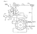
- Fig.1 is an appearance schematic view of the gas engine 100 which is carried out according to claims 1-3.
- a fuel gas feed pipe 2 equipped with a regulator 1 and a valve 5 on the way is connected to an intake port 11 communicated with a combustion chamber (not shown).
- an air feed pipe 8 equipped with an air cleaner 9 and a throttle 10 is connected to the intake port 11.
- the pressure of fuel gas is regulated by dozens of KPa (kilo pascal) extent from 2KPa (kilo pascal) extent by the regulator 1.
- the valve 5 is driven to open and close by the driver 12, therefore, the fuel gas can be fed from a nozzle (low voltage port injection) which is not shown of the fuel gas feed pipe into the intake port 11 and the fuel gas can be also shut.
- Air is defecated with an air cleaner 9 and the air of the amount according to the opening of the throttle 10 is fed in the intake port 11 from the air feed pipe 8.
- a gas engine 100 is put into operation with a starter which is not shown, an engine rotational frequency improves to 200 min -1 extent, and the pneumatic pressure in the intake port at an intake or suction stroke becomes lower (to negative pressure) than the pressure of the fuel gas in the fuel gas feed pipe 2.
- the regulator 1 regulates the pressure of the fuel gas so that the differential pressure of both may serve as hundreds mm aq.
- the regulator 1 is connected to the intake port 11 via the pressure balance line 3.
- a branch pipe 4 equipped with a valve 6 on the way is connected to the pressure balance line 3, and a valve 7 is provided in the downstream rather than the connect portion at which the branch pipe 4 is connected to the pressure balance line 3.
- the pressure balance line 3 is selectively communicated with the inside of the intake port 11 or the atmospheric by opening or closing the valve 6 and the valve 7(switching means for switching).
- the pressure in the intake port 11 at the time of starting is atmospheric pressure mostly, the pressure in the intake port 11 becomes high as the engine rotational frequency rises. When the engine rotational frequency reaches to rated rotational frequency, the pressure of the intake port 11 will be settled in the pressure of the fixed range.
- the pressure balance line 3 is communicated with the intake port 11 by closing the valve 6 and opening the valve 7, and the regulator 1 adjusts the feed pressure of the fuel gas on the basis of the pressure in the intake port 11.
- the pressure balance line 3 is made to communicated with the atmospheric air by closing the valve 7 and opening the valve 6, and the feed pressure of the fuel gas is adjusted on the basis of atmospheric pressure.
- an engine rotational frequency detection sensor 14 (engine rotational frequency detection means) is provided in the gas engine 100.
- the engine rotational frequency detection sensor 14 detects a signal and transmits the detected signal to ECU 13 (judgment means) through signal lines 15 and 16.
- ECU 13 includes a memory (not shown) which memorizes the tolerance of the differential pressure between the pressure of the fuel gas in the fuel gas feed pipe 2 and the pressure in the intake port 11. ECU 13 judges whether the difference between the pressure of the fuel gas in the fuel gas feed pipe 2 by the transmitted signal and the pressure in the intake port 11 is within the predetermined fixed range (tolerance range) which is memorized by the memory.
- the gas engine 100 continues to drive. If the differential pressures is not temporarily settled within the tolerance, the ECU 13 sends a control signal to the driver 12 through a signal line 17 to carry out switching operation of the valve 5 (adjustment means).
- engine rotational frequency exceeds tolerance, it will set up so that the open period of the valve 5 per 1 cycle may become short, and the amount of feed of the fuel gas to the intake port 11 will be reduced. Conversely, if so small that the engine rotational frequency does not fulfill tolerance, it will set up so that the open period of the valve 5 per 1 cycle may become long, and the amount of feed of the fuel gas to the intake port 11 will be increased.
- Fig.2 is a schematic view of the system near the intake port.
- a nozzle 25 is provided at the tip of the fuel gas feed pipe 2. Where a fuel gas feed port 28 is turned in the direction of a lower stream of a river of airstream 18, the nozzle 25 is connected with the fuel gas feed pipe 2. The nozzle 25 is installed in the condition of having projected in the intake port 11.
- a piston 23 moves in the direction to extend the volume of a combustion chamber 24 at the suction stroke, the fuel gas 19 which passed the open intake valve 21 and is mixed with airstream 18 is supplied to the combustion chamber 24 formed by the top face of a cylinder head 20, a cylinder liner 22 and a piston 23 etc.
- Fig.3 is a schematic view of the system showing the feed passage of the fuel gas to the intake port at the time of another starting with Fig.1 and Fig.2.
- the air feed pipe 8 located in an upper stream portion than a throttle 10 is connected to the fuel gas feed pipe 2 via a by-path pipe 26.
- a valve 27 is provided in the way of the by-path pipe 26.
- the fuel gas can also be supplied in the intake port 11 through the throttle 10 from the air feed pipe 8 by opening the valve 27.
- Fig.4 is a graph which shows the relation between the pressure of the fuel gas in the fuel-feed passage and the pressure in the intake port at the time of injecting fuel gas with high pressure in the intake port, and the output of the engine.
- Fig.5 is a graph shows the relation between the pressure of the fuel gas and the pressure in the intake port at the time of injecting fuel gas with high pressure in the intake port, and the output of the supercharge type engine (incidentally the gas engine 100 of this invention is a non-supercharged type).
- the engine rotational frequency detection sensor 14 detects the engine rotational frequency, and the open period amount of the valve 5 per 1 cycle is adjusted so that the amount of feed of the fuel gas per 1 cycle may turn into optimum dose. Consequently, it becomes possible to maintain the output uniformly easily.
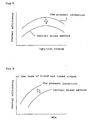
- Fig.6 is a graph which shows the relation between the throttle opening and the ignition timing in condition of the same output, both in the gas engine which is carried out according to the present invention and in the venturi mixer type gas engine.
- the throttle opening of the gas engine 100 which is carried out according to the present invention is always smaller without depending ignition timing rather than a throttle of a venturi mixer type gas engine.
- the throttle opening of the gas engine 100 which is carried out according to the present invention has allowances in the throttle opening rather than the throttle of a venturi mixer type gas engine.
- Fig.7 is a graph which shows the relation between the amount of discharge NO x and the ignition timing in condition of the fixed and rated output, both in the gas engine which carried out the present invention and in the venturi mixer type gas engine.
- Fig.8 is a graph which shows the relation between the thermal efficiency and the ignition timing in condition of the fixed and rated output both in the gas engine which is carried out according to the present invention and in the venturi mixer type gas engine.
- Fig.9 is a graph which shows the thermal efficiency in condition of the fixed and rated output of the gas engine 100 which carried out the presents invention, and the gas engine of a venturi mixer method, and the relation of the amount of discharge NOx.
- thermal efficiency of the gas engine 100 which is carried out according to the present invention is higher (about three to four points), and the amounts of discharge NOx is smaller or fewer.
- the present invention can be applied to a gas engine which is a non-supercharged type and supplies air and a fuel to a intake port, without mixing with a mixer.
Landscapes
- Engineering & Computer Science (AREA)
- Chemical & Material Sciences (AREA)
- Combustion & Propulsion (AREA)
- Mechanical Engineering (AREA)
- General Engineering & Computer Science (AREA)
- Chemical Kinetics & Catalysis (AREA)
- General Chemical & Material Sciences (AREA)
- Oil, Petroleum & Natural Gas (AREA)
- Output Control And Ontrol Of Special Type Engine (AREA)
- Electrical Control Of Air Or Fuel Supplied To Internal-Combustion Engine (AREA)
Abstract
Description
Claims (3)
- A fuel feed device of a gas engine which is a non-supercharged type engine and feeds air and a fuel to an intake port without mixing with a mixer:wherein the fuel gas is fed into the intake port by using negative pressure generated in the intake port,during an intake stroke.
- A fuel feed device of a gas engine according to claim 1 including:a detection means for detecting engine rotational frequency,a judgment means for judging whether the engine rotational frequency detected by said detection means is maintained within a fixed range which is predetermined,an adjustment means for adjusting a feed period of said fuel gas per 1 cycle so that the engine rotational frequency converges within the fixed range.
- A fuel feed device of a gas engine according to claim 1 or 2 including:a regulator and a valve which are prepared in a fuel gas feed passage sequentially from the upstream,a switching means for making a pressure balance line of said regulator selectively communicate with an inside of the intake port or atmospheric air,said pressure balance line at the time of starting communicates with the inside of the intake port by said switching means.
Applications Claiming Priority (3)
| Application Number | Priority Date | Filing Date | Title |
|---|---|---|---|
| JP2002018212 | 2002-01-28 | ||
| JP2002018212A JP3897602B2 (en) | 2002-01-28 | 2002-01-28 | Gas engine fuel supply system |
| PCT/JP2003/000633 WO2003064842A1 (en) | 2002-01-28 | 2003-01-24 | Fuel feed device of gas engine |
Publications (2)
| Publication Number | Publication Date |
|---|---|
| EP1471244A1 true EP1471244A1 (en) | 2004-10-27 |
| EP1471244A4 EP1471244A4 (en) | 2010-07-21 |
Family
ID=27653647
Family Applications (1)
| Application Number | Title | Priority Date | Filing Date |
|---|---|---|---|
| EP03734835A Withdrawn EP1471244A4 (en) | 2002-01-28 | 2003-01-24 | Fuel feed device of gas engine |
Country Status (6)
| Country | Link |
|---|---|
| US (1) | US7032568B2 (en) |
| EP (1) | EP1471244A4 (en) |
| JP (1) | JP3897602B2 (en) |
| KR (1) | KR20040071329A (en) |
| CN (1) | CN100462543C (en) |
| WO (1) | WO2003064842A1 (en) |
Families Citing this family (7)
| Publication number | Priority date | Publication date | Assignee | Title |
|---|---|---|---|---|
| JP4247191B2 (en) * | 2005-03-08 | 2009-04-02 | 三菱重工業株式会社 | Gas supply device and operation method for gas engine |
| CA2664130A1 (en) * | 2006-09-21 | 2008-03-27 | Merck & Co., Inc. | Piperidine and pyrrolidine beta-secretase inhibitors for the treatment of alzheimer's disease |
| JP4563443B2 (en) * | 2007-12-14 | 2010-10-13 | 三菱重工業株式会社 | Gas engine system control method and system |
| DE102009023674A1 (en) * | 2009-06-03 | 2010-12-23 | I-Tecc Gmbh Innovative Technologies & Consulting | internal combustion engine |
| CN103075274B (en) * | 2013-01-18 | 2015-01-21 | 无锡市贝尔机械有限公司 | Air inlet mixer and casting process thereof |
| CN109184961A (en) * | 2018-10-04 | 2019-01-11 | 李晨天 | Air inlet (discrimination) pipe vacuum suction gaseous fuel Supply Method and device |
| JP7470272B2 (en) * | 2020-02-17 | 2024-04-18 | 株式会社ニッキ | Gas fuel supply system for engines |
Family Cites Families (15)
| Publication number | Priority date | Publication date | Assignee | Title |
|---|---|---|---|---|
| US3125085A (en) * | 1964-03-17 | Control of fuel introduction to engine cylinder | ||
| US2209206A (en) * | 1938-09-28 | 1940-07-23 | Reynold A Peduzzi | Gas carburetor |
| FR888112A (en) * | 1942-04-20 | 1943-12-03 | Advanced mixer for combustible gases | |
| US4576137A (en) * | 1981-06-19 | 1986-03-18 | Yanmar Diesel Engine Co., Ltd. | Gas-diesel dual fuel engine |
| JPS5947338U (en) * | 1982-09-22 | 1984-03-29 | 日産ディーゼル工業株式会社 | Diesel engine fuel supply system |
| JPS61218758A (en) * | 1985-03-25 | 1986-09-29 | Yanmar Diesel Engine Co Ltd | Fuel feeder for premix gas engine |
| JPH0223258A (en) * | 1988-07-11 | 1990-01-25 | Yamaha Motor Co Ltd | Gas engine |
| JPH07111161B2 (en) * | 1989-08-28 | 1995-11-29 | 三國工業株式会社 | Gas injection device |
| CA2098192C (en) * | 1991-10-11 | 2004-11-16 | Thomas G. Ausman | Damped actuator and valve assembly for an electronically-controlled injection |
| JP3075685B2 (en) * | 1995-09-04 | 2000-08-14 | 本田技研工業株式会社 | Fuel injection method for gaseous fuel engine |
| JPH09250401A (en) * | 1995-10-06 | 1997-09-22 | Nippon Carbureter Co Ltd | Gas fuel supply system for engine |
| US5673673A (en) * | 1996-04-30 | 1997-10-07 | Servojet Products International | Method and apparatus for the high Mach injection of a gaseous fuel into an internal combustion engine |
| JP2001003774A (en) * | 1999-06-18 | 2001-01-09 | Tokyo Gas Co Ltd | Sub-chamber gas engine and operation control method thereof |
| JP2001214811A (en) | 2000-02-03 | 2001-08-10 | Niigata Eng Co Ltd | Fuel gas supply device and fuel gas supply method for gas engine |
| KR100608404B1 (en) * | 2002-02-15 | 2006-08-02 | 피피지 인더스트리즈 오하이오 인코포레이티드 | Radiation-curable composition containing a copolymer of isobutylene and acrylic monomers |
-
2002
- 2002-01-28 JP JP2002018212A patent/JP3897602B2/en not_active Expired - Fee Related
-
2003
- 2003-01-24 CN CNB038027585A patent/CN100462543C/en not_active Expired - Fee Related
- 2003-01-24 WO PCT/JP2003/000633 patent/WO2003064842A1/en not_active Ceased
- 2003-01-24 KR KR10-2004-7011277A patent/KR20040071329A/en not_active Ceased
- 2003-01-24 EP EP03734835A patent/EP1471244A4/en not_active Withdrawn
- 2003-01-24 US US10/501,871 patent/US7032568B2/en not_active Expired - Lifetime
Also Published As
| Publication number | Publication date |
|---|---|
| CN1623032A (en) | 2005-06-01 |
| US20050000490A1 (en) | 2005-01-06 |
| CN100462543C (en) | 2009-02-18 |
| KR20040071329A (en) | 2004-08-11 |
| JP3897602B2 (en) | 2007-03-28 |
| EP1471244A4 (en) | 2010-07-21 |
| JP2003214257A (en) | 2003-07-30 |
| WO2003064842A1 (en) | 2003-08-07 |
| US7032568B2 (en) | 2006-04-25 |
Similar Documents
| Publication | Publication Date | Title |
|---|---|---|
| US5785025A (en) | Fuel supply for international combustion engine | |
| CN101858265B (en) | Fuel injector flow correction system for direct injection engines | |
| US5207204A (en) | Method of and an apparatus for supplying assist air into a combustion chamber direct injecting fuel injection valve | |
| EP0964150A3 (en) | Fuel injection system for internal combustion engine | |
| JP2550026B2 (en) | Liquid fuel distribution method and device for internal combustion engine | |
| JP2001207928A (en) | Fuel supply control device for internal combustion engine | |
| US7877996B2 (en) | Turbo-lag compensation system having an ejector | |
| US7032568B2 (en) | Fuel feed device of gas engine | |
| EP1617061A4 (en) | Idling speed controller of internal combustion engine, internal combustion engine controller and internal combustion engine | |
| JP2002523668A (en) | Control method of fuel injection system | |
| EP0849452A3 (en) | Apparatus and method for controlling fuel injection in internal combustion engine | |
| JPH02286871A (en) | Fuel injection device | |
| KR100692132B1 (en) | Cutoff Solenoid Injector Structure | |
| JPS6296776A (en) | Fuel feeder for itnernal combustion engine | |
| JPH08158951A (en) | Gas fuel supply system for engine | |
| JPS62298646A (en) | Fuel injection equipment of engine | |
| CN121322336A (en) | Air compressor device driven by internal combustion engine and working method thereof | |
| JP2000130264A (en) | Compound mixer for gas fuel | |
| KR930003259Y1 (en) | Turbocharger Control | |
| JPH05215045A (en) | Auxiliary air supply for engine | |
| JPH01273840A (en) | Fuel injector for engine | |
| JPS60159359A (en) | Gaseous fuel feed device | |
| WO2008149385A1 (en) | Variable pressure fuel injection system of a vehicle | |
| JPS63201334A (en) | Fuel control method for engine | |
| JPS59136523A (en) | Fuel supplying apparatus for engine |
Legal Events
| Date | Code | Title | Description |
|---|---|---|---|
| PUAI | Public reference made under article 153(3) epc to a published international application that has entered the european phase |
Free format text: ORIGINAL CODE: 0009012 |
|
| 17P | Request for examination filed |
Effective date: 20040715 |
|
| AK | Designated contracting states |
Kind code of ref document: A1 Designated state(s): AT BE BG CH CY CZ DE DK EE ES FI FR GB GR HU IE IT LI LU MC NL PT SE SI SK TR |
|
| AX | Request for extension of the european patent |
Extension state: AL LT LV MK RO |
|
| A4 | Supplementary search report drawn up and despatched |
Effective date: 20100621 |
|
| GRAC | Information related to communication of intention to grant a patent modified |
Free format text: ORIGINAL CODE: EPIDOSCIGR1 |
|
| GRAP | Despatch of communication of intention to grant a patent |
Free format text: ORIGINAL CODE: EPIDOSNIGR1 |
|
| RIC1 | Information provided on ipc code assigned before grant |
Ipc: F02M 21/02 20060101AFI20110427BHEP |
|
| STAA | Information on the status of an ep patent application or granted ep patent |
Free format text: STATUS: THE APPLICATION IS DEEMED TO BE WITHDRAWN |
|
| 18D | Application deemed to be withdrawn |
Effective date: 20111025 |