EP1471162A1 - Procédé d'obtention d'une barrière thermique flexo-adaptive - Google Patents
Procédé d'obtention d'une barrière thermique flexo-adaptive Download PDFInfo
- Publication number
- EP1471162A1 EP1471162A1 EP04290944A EP04290944A EP1471162A1 EP 1471162 A1 EP1471162 A1 EP 1471162A1 EP 04290944 A EP04290944 A EP 04290944A EP 04290944 A EP04290944 A EP 04290944A EP 1471162 A1 EP1471162 A1 EP 1471162A1
- Authority
- EP
- European Patent Office
- Prior art keywords
- torch
- blade
- ceramic layer
- thermal barrier
- layer
- Prior art date
- Legal status (The legal status is an assumption and is not a legal conclusion. Google has not performed a legal analysis and makes no representation as to the accuracy of the status listed.)
- Withdrawn
Links
- 238000000034 method Methods 0.000 title claims description 17
- 230000008569 process Effects 0.000 title description 6
- 239000012720 thermal barrier coating Substances 0.000 title 1
- 239000000919 ceramic Substances 0.000 claims abstract description 45
- 230000004888 barrier function Effects 0.000 claims abstract description 41
- 239000000758 substrate Substances 0.000 claims abstract description 10
- 238000001816 cooling Methods 0.000 claims abstract description 7
- 238000007751 thermal spraying Methods 0.000 claims abstract description 6
- 238000000151 deposition Methods 0.000 claims abstract description 5
- 239000000463 material Substances 0.000 claims description 14
- 238000006073 displacement reaction Methods 0.000 claims description 5
- 238000004519 manufacturing process Methods 0.000 abstract 1
- 230000001105 regulatory effect Effects 0.000 abstract 1
- 235000010599 Verbascum thapsus Nutrition 0.000 description 30
- 238000000576 coating method Methods 0.000 description 6
- 238000001000 micrograph Methods 0.000 description 6
- 239000011248 coating agent Substances 0.000 description 5
- 230000007797 corrosion Effects 0.000 description 5
- 238000005260 corrosion Methods 0.000 description 5
- PXHVJJICTQNCMI-UHFFFAOYSA-N nickel Substances [Ni] PXHVJJICTQNCMI-UHFFFAOYSA-N 0.000 description 4
- 230000035939 shock Effects 0.000 description 4
- 244000178289 Verbascum thapsus Species 0.000 description 3
- 238000002485 combustion reaction Methods 0.000 description 3
- 229910052759 nickel Inorganic materials 0.000 description 3
- 229910003266 NiCo Inorganic materials 0.000 description 2
- 239000000567 combustion gas Substances 0.000 description 2
- 230000006378 damage Effects 0.000 description 2
- 230000000694 effects Effects 0.000 description 2
- 238000005328 electron beam physical vapour deposition Methods 0.000 description 2
- 230000035784 germination Effects 0.000 description 2
- 238000010438 heat treatment Methods 0.000 description 2
- 230000001788 irregular Effects 0.000 description 2
- 238000007254 oxidation reaction Methods 0.000 description 2
- 239000000843 powder Substances 0.000 description 2
- 230000000750 progressive effect Effects 0.000 description 2
- 230000001737 promoting effect Effects 0.000 description 2
- 229910000601 superalloy Inorganic materials 0.000 description 2
- 230000008646 thermal stress Effects 0.000 description 2
- 241001080024 Telles Species 0.000 description 1
- 240000008042 Zea mays Species 0.000 description 1
- 230000004075 alteration Effects 0.000 description 1
- 239000012080 ambient air Substances 0.000 description 1
- 230000015572 biosynthetic process Effects 0.000 description 1
- 238000005336 cracking Methods 0.000 description 1
- 238000005520 cutting process Methods 0.000 description 1
- 230000007423 decrease Effects 0.000 description 1
- 230000032798 delamination Effects 0.000 description 1
- 230000008021 deposition Effects 0.000 description 1
- 238000005137 deposition process Methods 0.000 description 1
- 230000001627 detrimental effect Effects 0.000 description 1
- 230000006870 function Effects 0.000 description 1
- 230000004927 fusion Effects 0.000 description 1
- 230000017525 heat dissipation Effects 0.000 description 1
- 230000008018 melting Effects 0.000 description 1
- 238000002844 melting Methods 0.000 description 1
- 239000012768 molten material Substances 0.000 description 1
- 230000003647 oxidation Effects 0.000 description 1
- 238000007750 plasma spraying Methods 0.000 description 1
- 239000011148 porous material Substances 0.000 description 1
- 230000001902 propagating effect Effects 0.000 description 1
- 230000035945 sensitivity Effects 0.000 description 1
- 238000000926 separation method Methods 0.000 description 1
- 238000007711 solidification Methods 0.000 description 1
- 230000008023 solidification Effects 0.000 description 1
- 238000004901 spalling Methods 0.000 description 1
- 230000035882 stress Effects 0.000 description 1
- 239000000126 substance Substances 0.000 description 1
- 239000012808 vapor phase Substances 0.000 description 1
- 238000003466 welding Methods 0.000 description 1
- 229910052845 zircon Inorganic materials 0.000 description 1
- GFQYVLUOOAAOGM-UHFFFAOYSA-N zirconium(iv) silicate Chemical compound [Zr+4].[O-][Si]([O-])([O-])[O-] GFQYVLUOOAAOGM-UHFFFAOYSA-N 0.000 description 1
Images

Classifications
-
- C—CHEMISTRY; METALLURGY
- C23—COATING METALLIC MATERIAL; COATING MATERIAL WITH METALLIC MATERIAL; CHEMICAL SURFACE TREATMENT; DIFFUSION TREATMENT OF METALLIC MATERIAL; COATING BY VACUUM EVAPORATION, BY SPUTTERING, BY ION IMPLANTATION OR BY CHEMICAL VAPOUR DEPOSITION, IN GENERAL; INHIBITING CORROSION OF METALLIC MATERIAL OR INCRUSTATION IN GENERAL
- C23C—COATING METALLIC MATERIAL; COATING MATERIAL WITH METALLIC MATERIAL; SURFACE TREATMENT OF METALLIC MATERIAL BY DIFFUSION INTO THE SURFACE, BY CHEMICAL CONVERSION OR SUBSTITUTION; COATING BY VACUUM EVAPORATION, BY SPUTTERING, BY ION IMPLANTATION OR BY CHEMICAL VAPOUR DEPOSITION, IN GENERAL
- C23C4/00—Coating by spraying the coating material in the molten state, e.g. by flame, plasma or electric discharge
- C23C4/18—After-treatment
-
- C—CHEMISTRY; METALLURGY
- C23—COATING METALLIC MATERIAL; COATING MATERIAL WITH METALLIC MATERIAL; CHEMICAL SURFACE TREATMENT; DIFFUSION TREATMENT OF METALLIC MATERIAL; COATING BY VACUUM EVAPORATION, BY SPUTTERING, BY ION IMPLANTATION OR BY CHEMICAL VAPOUR DEPOSITION, IN GENERAL; INHIBITING CORROSION OF METALLIC MATERIAL OR INCRUSTATION IN GENERAL
- C23C—COATING METALLIC MATERIAL; COATING MATERIAL WITH METALLIC MATERIAL; SURFACE TREATMENT OF METALLIC MATERIAL BY DIFFUSION INTO THE SURFACE, BY CHEMICAL CONVERSION OR SUBSTITUTION; COATING BY VACUUM EVAPORATION, BY SPUTTERING, BY ION IMPLANTATION OR BY CHEMICAL VAPOUR DEPOSITION, IN GENERAL
- C23C4/00—Coating by spraying the coating material in the molten state, e.g. by flame, plasma or electric discharge
- C23C4/02—Pretreatment of the material to be coated, e.g. for coating on selected surface areas
-
- C—CHEMISTRY; METALLURGY
- C23—COATING METALLIC MATERIAL; COATING MATERIAL WITH METALLIC MATERIAL; CHEMICAL SURFACE TREATMENT; DIFFUSION TREATMENT OF METALLIC MATERIAL; COATING BY VACUUM EVAPORATION, BY SPUTTERING, BY ION IMPLANTATION OR BY CHEMICAL VAPOUR DEPOSITION, IN GENERAL; INHIBITING CORROSION OF METALLIC MATERIAL OR INCRUSTATION IN GENERAL
- C23C—COATING METALLIC MATERIAL; COATING MATERIAL WITH METALLIC MATERIAL; SURFACE TREATMENT OF METALLIC MATERIAL BY DIFFUSION INTO THE SURFACE, BY CHEMICAL CONVERSION OR SUBSTITUTION; COATING BY VACUUM EVAPORATION, BY SPUTTERING, BY ION IMPLANTATION OR BY CHEMICAL VAPOUR DEPOSITION, IN GENERAL
- C23C4/00—Coating by spraying the coating material in the molten state, e.g. by flame, plasma or electric discharge
- C23C4/12—Coating by spraying the coating material in the molten state, e.g. by flame, plasma or electric discharge characterised by the method of spraying
- C23C4/134—Plasma spraying
Definitions
- the invention relates to flexo-adaptive thermal barriers, that is to say to thermal barriers with sufficient flexibility to adapt to deformation of the substrate, whether of mechanical or dilatometric origin under the effect of a thermal gradient.
- the invention relates more particularly to a method economical to obtain such barriers by thermal spraying.
- substantially tangential directions will be called “horizontal” on the surface of the part on which the thermal barrier is applied.
- the thermal barriers thus obtained by plasma projection are therefore reserved for fixed parts not subjected to thermal shocks such as combustion chambers.
- the ceramic layer is of the order of 0.3mm and its lifespan is perfectly in this case.
- thermal barrier having a cohesion of material high and a grip of the most resistant.
- a first problem to be solved is to improve the resistance to flaking of the barriers. thermal.
- a second problem to solve is to reduce the cost of developing a barrier thermal.
- a thermal barrier in order to be resistant to both thermal stresses high at the surface of the substrate and at high mechanical stresses thereof, and by the same to answer the first problem posed, must be flexible in the directions tangential to the surface it covers. To this end, it is necessary to introduce vertical cracks from the surface of the thermal barrier to the substrate or the undercoat, that is to say crossing the entire ceramic layer.
- the invention provides a process for obtaining a flexo-adpative thermal barrier, the thermal barrier comprising a ceramic layer (44) with a thickness at least equal to 80 ⁇ m, deposited on a substrate (40) covered with a sublayer (42), the ceramic layer (44) being deposited by thermal spraying using a torch (30) called "plasma arc", the operation of the torch being defined by the power of the torch , the material flow, the distance from the torch to the workpiece (10) to be coated and the speed of movement of the torch relative to the workpiece.
- a torch (30) called "plasma arc"
- Such a method is remarkable in that it consists in depositing, directly on the underlay and in a single pass, the ceramic layer while maintaining a projection distance between 20mm and 90mm, the speed of movement of the torch being between 2mm / s and 10mm / s, the material flow being between 2mm / s and 10mm / s and the arc intensity of the torch being between 500A and 800A, so as to obtain after cooling , at least 2 substantially vertical cracks per millimeter and crossing the entire ceramic layer.
- the power of the torch being adjusted to a high value and the ceramic layer produced in a single pass, the new drops of molten material arrive on material still very hot, which causes an excellent bond by welding between the ceramic grains in the vertical direction.
- This is favored by the choice of the speed of movement of the torch as low as possible, preferably between 2mm / s and 10mm / s.
- the temperature at the location of the deposit is high, which makes it possible to obtain a dense microstructure with a number of horizontal micro cracks, reduced delaminations and pores, and better cohesion of the material. Projection in a single pass is an important parameter directly affecting the resistance to flaking of the thermal barrier.
- the cohesion between the different layers of material deposited on each pass is lower than within the same layer.
- a horizontal crack can then be initiated between two layers, which is detrimental for the behavior of the thermal barrier.
- the ceramic layer thus formed under the jet being very hot, its cooling in contact with ambient air, when the jet has moved, causes a significant vertical thermal gradient, this gradient promoting the formation of cracks at the surface of the ceramic layer, these cracks then propagating vertically to the sub-layer, thus passing through the entire ceramic layer.
- the inventors have observed that these two phenomena appear simultaneously. With too low a power, the cracks are spaced, very irregular and the vertical connections between the grains of material are poor.
- the inventors By increasing the power of the torch, the cracks are more dense and homogeneous and the vertical connections between the grains are simultaneously improved. With sufficient power, that is to say sufficiently large to obtain a crack density at least equal to the claimed value, the inventors obtain a thermal barrier having a satisfactory flaking resistance up to a thickness of the ceramic layer of 250 ⁇ m, the optimal quality being however between 100 ⁇ m and 150 ⁇ m. Note that the power of the torch appropriate to obtain this result depends on many parameters such as the ceramic used heat dissipation in the room, the powder flow, the width of the jet, the coefficient of loss of the torch, etc. Note also that those skilled in the art will however limit the power of the torch so as not to cause excessive heating which could cause the melting of the substrate or an inadmissible alteration of its granular structure.
- the dimensions of the cracks, as well as the number of cracks per mm, depend on the thickness of the deposit The thicker the deposit, the larger the cracks and their number per mm low.
- the thickness of the ceramic layer obtained in a single pass is obviously function of material flow, distance from torch to workpiece and speed of displacement of the torch, i.e. of the jet, relative to the workpiece, as well as of the torch loss coefficient. So the thickness of the ceramic layer increases with the flow of material, but this thickness decreases when the distance or the speed increases. Those skilled in the art will experimentally define these parameters at case by case depending on the material at its disposal.
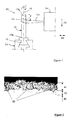
- Figure 1 illustrates the deposition of the ceramic layer with a plasma torch.
- Figure 2 is a sectional micrograph of the thermal barrier thus obtained.
- Figure 3 is a micrograph of the surface of the thermal barrier.
- the part to be coated with a thermal barrier is a turbine blade 10 made of superalloy nickel base with directed solidification.
- the thermal barrier comprises an underlay of McrAIY covered by a ceramic layer of 125 ⁇ m in ZrO 2 zircon with 8% of ytrin Y 2 O 3 .
- the blade 12 of the blade 10 is covered with a sub-layer of McrAIY deposited according to the usual procedures.
- the blade 10 is then held by its foot 14 on a rotating assembly 20 capable of rotate the dawn on its axis 16, i.e. on itself in the direction of the length, the blade 12 being presented in front of a plasma torch 30, the jet of which will be referenced 32
- the plasma torch 32 is here the F4 model marketed by the company whose the company name is Sultzer Metco.
- the torch is placed 50mm from the blade 10, the blade 10 then being rotated on its axis 16.
- THE torch 30 is put into operation and the jet 32 first touches the vertex 18a of dawn 10 and gradually moves towards foot 14 to reach the other end 18b of the blade 12 and thus form on the surface of the blade 10 a ceramic layer 44 having the shape of a helix with contiguous turns.
- Jet 32 is moves on the surface of the blade 12 at a resulting speed of 6mm / s.
- Powder flow is 70g / mm, and the power of the torch is obtained with an arc intensity of 700A
- the torch setting is said to be "hot", the temperature of the deposit is 550 ° C. this temperature being measured on the surface of the deposit just after the passage of the jet 32 and 10mm behind the jet
- FIG. 40, 42 and 44 are respectively referenced the substrate, the sub-layer and the ceramic layer thus obtained.
- the cracks are referenced 50.
- the cracks 50 are substantially vertical, that is to say substantially perpendicular to the substrate 40.
- the two edges of the cracks 50 may be parallel or open towards the surface or towards the under-layer 42.
- the characteristic primordial of the cracks 50 is that they travel from the surface to the under-layer 42, crossing the entire thickness of the ceramic layer 44, as illustrated in the micrograph.
- the cracks 50 form a locally irregular but statistically homogeneous and anisotropic network, these cracks 50 providing the thermal barrier with the flexibility required in a tangential plane to the substrate 40.
- the density of cracks is defined as being the average number of cracks per millimeter cutting any geometric line.
Landscapes
- Chemical & Material Sciences (AREA)
- Engineering & Computer Science (AREA)
- Physics & Mathematics (AREA)
- Plasma & Fusion (AREA)
- Chemical Kinetics & Catalysis (AREA)
- Materials Engineering (AREA)
- Mechanical Engineering (AREA)
- Metallurgy (AREA)
- Organic Chemistry (AREA)
- Coating By Spraying Or Casting (AREA)
- Turbine Rotor Nozzle Sealing (AREA)
Abstract
Description
Une barrière thermique est constituée aujourd'hui habituellement par :
- une sous-couche alumineuse de NiPtAl ou de McrAlY (M = Fe, Ni, Co et NiCo) formant un obstacle chimique à l'oxydation et à la corrosion ;
- une couche de céramique ZrO2-Y O thermiquement isolante.
- de mieux contrôler l'épaisseur du revêtement ;
- de réduire l'échauffement de la barrière thermique et d'éviter ainsi les fissurations et l'écaillage du revêtement lors de son refroidissement.
- La couche de céramique est peu flexible selon les directions tangentielles à la surface de la pièce. Par conséquent, les barrières thermiques ainsi obtenues résistent mal aux chocs thermiques importants, par exemple au niveau des aubes de turbines, ces barrières thermiques s'écaillant et se détachant assez rapidement.
- Les liaisons verticales entre les couches élémentaires sont imparfaites car elles sont assurées par les micro soudures se formant lorsque les gouttelettes de céramique en fusion arrivent sur la céramique précédemment déposée et partiellement refroidie. De ce fait, les couches élémentaires de céramique constituant de telles barrières thermiques tendent à se séparer sous l'effet des chocs thermiques, ce qui provoque également l'écaillage de la barrière thermique.
Un tel procédé présente cependant deux inconvénients :
- Le revêtement en plusieurs passes séparées par une étape de refroidissement entraíne un coût supplémentaire,
- Ce procédé présente l'inconvénient habituel des revêtements multicouches précédemment décrits, à savoir des liaisons imparfaites par micro soudures entre les couches élémentaires favorisant la séparation de ces couches élémentaires et l'écaillage de la barrière thermique. Cet inconvénient est aggravé par le refroidissement du dépôt effectué entre chaque couche élémentaire.
Un tel procédé présente cependant deux inconvénients :
- Il est lent et coûteux ,
- La barrière thermique conserve malgré tout une durée de vie limitée, car les gaz de combustion chauds et corrosifs atteignent la sous-couche par les espaces réduits mais très nombreux entre les colonnes, la corrosion progressive de la sous-couche provoquant se destruction et l'écaillage de la barrière thermique.
Un tel procédé est remarquable en ce que qu'il consiste à déposer, directement sur la sous-couche et en une seule et unique passe, la couche de céramique en maintenant une distance de projection comprise entre 20mm et 90mm, la vitesse de déplacement de la torche étant comprise entre 2mm/s et 10mm/s, le débit de matière étant compris entre 2mm/s et 10mm/s et l'intensité d'arc de la torche étant comprise entre 500A et 800A, de façon à obtenir après refroidissement, au moins 2 fissures sensiblement verticales par millimètre et traversant toute la couche de céramique.
Par ailleurs, la couche de céramique ainsi formée sous le jet étant très chaude, son refroidissement au contact de l'air ambiant, lorsque le jet s'est déplacé, provoque un gradient thermique vertical important, ce gradient favorisant la formation de fissures à la surface de la couche de céramique, ces fissures se propageant ensuite verticalement jusqu'à la sous-couche, traversant ainsi toute la couche de céramique.
Les inventeurs ont constaté que ces deux phénomènes apparaissent simultanément. Avec une puissance trop faible, les fissures sont espacées, très irrégulières et les liaisons verticales entre les grains de matière sont médiocres. En augmentant la puissance de la torche, les fissures sont plus denses et homogènes et les liaisons verticales entre les grains sont simultanément améliorées. Avec une puissance suffisante, c'est à dire suffisamment importante pour obtenir une densité de fissures au moins égale à la valeur revendiquée, les inventeurs obtiennent une barrière thermique présentant une résistance à l'écaillage satisfaisante jusqu'à une épaisseur de la couche de céramique de 250µm, la qualité optimale se situant cependant entre 100µm et 150µm. A noter que la puissance de la torche appropriée pour obtenir ce résultat dépend de nombreux paramètres tels que la céramique utilisée la dissipation thermique dans la pièce, le débit de poudre, la largeur du jet, le coefficient de déperdition de la torche, etc
A noter également que l'homme du métier limitera toutefois la puissance de la torche pour ne pas provoquer un échauffement excessif risquant d'entraíner la fusion du substrat ou une altération non admissible de sa structure granulaire.
Un tel procédé est remarquable en ce qu'il consiste :
Sont référencés 40, 42 et 44 respectivement le substrat, la sous-couche et la couche de céramique ainsi obtenue. Les fissures sont référencées 50. Sur cette micrographie, on compte 4,8 fissures par millimètre dont la distance moyenne est de 200µm. Comme le montre la micrographie, les fissures 50 sont sensiblement verticales, c'est à dire sensiblement perpendiculaires au substrat 40. Les deux bords des fissures 50 peuvent être parallèles ou s'ouvrir vers la surface ou vers la sous-couche 42. La caractéristique primordiale des fissures 50 est qu'elles cheminent de la surface vers la sous-couche 42, en traversant toute l'épaisseur de la couche de céramique 44, comme illustré sur la micrographie.
On voit sur cette micrographie que les fissures 50 forment un réseau localement irrégulier mais statistiquement homogène et anisotrope, ces fissures 50 apportant à la barrière thermique la flexibilité requise suivant un plan tangentiel au substrat 40. Le densité de fissures est définie comme étant le nombre moyen de fissures par millimètre coupant un droite géométrique quelconque.
Claims (2)
- Procédé d'obtention d'une barrière thermique flexo-adaptive, la barrière thermique comportant une couche de céramique (44) d'une épaisseur au moins égale à 80µm, déposée sur un substrat (40) recouvert d'une sous-couche (42), la couche de céramique (44) étant déposée par projection thermique à l'aide d'une torche (30) dite "à arc plasma", le fonctionnement de la torche étant défini par la puissance de la torche, le débit de matière, la distance de la torche à la pièce (10) à revêtir et la vitesse de déplacement de la torche par rapport à la pièce
caractérisé en ce qu'il consiste à déposer, directement sur la sous-couche et en une seule et unique passe, la couche de céramique en maintenant une distance de projection comprise entre 20mm et 90mm, la vitesse de déplacement de la torche étant comprise entre 2mm/s et 10mm/s, le débit de matière étant compris entre 2mm/s et 10mm/s et l'intensité d'arc de la torche étant comprise entre 500A et 800A, de façon à obtenir après refroidissement, au moins 2 fissures sensiblement verticales par millimètre et traversant toute la couche de céramique. - Procédé selon la revendication 1, la pièce (10) étant une aube d'axe géométrique (16) comportant une pale (12) et un pied (14), la couche de céramique (44) étant appliquée sur la pale (12),
caractérisé en ce qu'il consiste :a. à maintenir le pied (14) de l'aube (10) par un outillage (20) pivotant à une vitesse de rotation V selon son axe géométrique (16),b. à exposer la pale (12) au jet (32) d'une torche (30) susceptible d'un déplacement relatif D1 parallèle à l'axe géométrique (16) et d'un déplacement relatif D2 perpendiculaire à l'axe géométrique (16) ;c. à effectuer la projection de céramique en un seul déplacement du jet (32) depuis l'une des extrémités (18a, 18b) jusqu'à son autre extrémité(18b, 18a) de la pale, l'aube (10) étant mise en rotation selon l'axe géométrique (16), la torche (30) étant déplacée selon D2 pour rester à une distance constante de la surface de la pale (12), la torche (30) étant déplacée suivant D1 pour former à la surface de la pale (12) une couche de céramique (44) en spirale de pas égal à la largeur du jet (32).
Applications Claiming Priority (2)
| Application Number | Priority Date | Filing Date | Title |
|---|---|---|---|
| FR0305086A FR2854166B1 (fr) | 2003-04-25 | 2003-04-25 | Procede d'obtention d'une barriere thermique flexo-adaptative |
| FR0305086 | 2003-04-25 |
Publications (1)
| Publication Number | Publication Date |
|---|---|
| EP1471162A1 true EP1471162A1 (fr) | 2004-10-27 |
Family
ID=32947379
Family Applications (1)
| Application Number | Title | Priority Date | Filing Date |
|---|---|---|---|
| EP04290944A Withdrawn EP1471162A1 (fr) | 2003-04-25 | 2004-04-09 | Procédé d'obtention d'une barrière thermique flexo-adaptive |
Country Status (3)
| Country | Link |
|---|---|
| EP (1) | EP1471162A1 (fr) |
| FR (1) | FR2854166B1 (fr) |
| RU (1) | RU2263157C1 (fr) |
Cited By (1)
| Publication number | Priority date | Publication date | Assignee | Title |
|---|---|---|---|---|
| WO2012004525A1 (fr) | 2010-07-06 | 2012-01-12 | Snecma | Barriere thermique pour aube de turbine, a structure colonnaire avec des colonnes espacees |
Families Citing this family (2)
| Publication number | Priority date | Publication date | Assignee | Title |
|---|---|---|---|---|
| EP1862568A1 (fr) | 2006-05-30 | 2007-12-05 | Siemens Aktiengesellschaft | Système de barrière thermique avec une structure à base de tungstène bronze |
| FR3013360B1 (fr) | 2013-11-19 | 2015-12-04 | Snecma | Procede integre de frittage pour microfissuration et tenue a l'erosion des barrieres thermiques |
Citations (2)
| Publication number | Priority date | Publication date | Assignee | Title |
|---|---|---|---|---|
| US5897921A (en) * | 1997-01-24 | 1999-04-27 | General Electric Company | Directionally solidified thermal barrier coating |
| EP1295964A2 (fr) * | 2001-09-24 | 2003-03-26 | Siemens Westinghouse Power Corporation | Revêtement barrière thermique à double microstructure |
Family Cites Families (5)
| Publication number | Priority date | Publication date | Assignee | Title |
|---|---|---|---|---|
| US5073433B1 (en) * | 1989-10-20 | 1995-10-31 | Praxair Technology Inc | Thermal barrier coating for substrates and process for producing it |
| WO1993024672A1 (fr) * | 1992-05-29 | 1993-12-09 | United Technologies Corporation | Revetement en ceramique formant une barriere thermique pour pieces soumises a des cycles thermiques rapides |
| US6102656A (en) * | 1995-09-26 | 2000-08-15 | United Technologies Corporation | Segmented abradable ceramic coating |
| US6306517B1 (en) * | 1996-07-29 | 2001-10-23 | General Electric Company | Thermal barrier coatings having an improved columnar microstructure |
| CA2211961C (fr) * | 1997-07-29 | 2001-02-27 | Pyrogenesis Inc. | Composants multicouches de systemes de combustion d'une grande precision dimensionnelle formes par projection plasma sous vide et methode de fabrication de ces derniers |
-
2003
- 2003-04-25 FR FR0305086A patent/FR2854166B1/fr not_active Expired - Lifetime
-
2004
- 2004-04-09 EP EP04290944A patent/EP1471162A1/fr not_active Withdrawn
- 2004-04-23 RU RU2004112560/02A patent/RU2263157C1/ru not_active IP Right Cessation
Patent Citations (2)
| Publication number | Priority date | Publication date | Assignee | Title |
|---|---|---|---|---|
| US5897921A (en) * | 1997-01-24 | 1999-04-27 | General Electric Company | Directionally solidified thermal barrier coating |
| EP1295964A2 (fr) * | 2001-09-24 | 2003-03-26 | Siemens Westinghouse Power Corporation | Revêtement barrière thermique à double microstructure |
Cited By (2)
| Publication number | Priority date | Publication date | Assignee | Title |
|---|---|---|---|---|
| WO2012004525A1 (fr) | 2010-07-06 | 2012-01-12 | Snecma | Barriere thermique pour aube de turbine, a structure colonnaire avec des colonnes espacees |
| JP2013543073A (ja) * | 2010-07-06 | 2013-11-28 | スネクマ | 間隔を空けて配置された柱を備える柱状構造を有しているタービンの羽根用の断熱層 |
Also Published As
| Publication number | Publication date |
|---|---|
| FR2854166A1 (fr) | 2004-10-29 |
| RU2263157C1 (ru) | 2005-10-27 |
| FR2854166B1 (fr) | 2007-02-09 |
Similar Documents
| Publication | Publication Date | Title |
|---|---|---|
| EP1990633B1 (fr) | Dispositif de mesure de déformations et son procédé de fabrication | |
| EP2540433B1 (fr) | Procédé de rechargement d'un moule de verrerie par rechargement laser de poudres | |
| EP3017084B1 (fr) | Procede de preparation a la depose d'un revetement metallique par projection thermique sur un substrat | |
| EP3429787B1 (fr) | Procede de fabrication d'une plaque abradable et de reparation d'un anneau de turbine | |
| FR2698105A1 (fr) | Pièce en un substrat de base métallique comportant un revêtement céramique. | |
| FR2827311A1 (fr) | Procede de reparation locale de pieces revetues d'une barriere thermique | |
| WO2017158264A1 (fr) | Procede de fabrication d'un anneau de turbine pour turbomachine | |
| FR2463752A1 (fr) | Poudre pour la formation d'un enduit a proprietes thermiques | |
| EP0269480B1 (fr) | Revêtement métallique réalisé sur un substrat minéral | |
| EP2042618B1 (fr) | Procédé de récupération d'éléments de turbomachine | |
| FR2854166A1 (fr) | Procede d'obtention d'une barriere thermique flexo-adaptative | |
| EP1645654A1 (fr) | Procédé d'obtention d'une barrière thermique flexo-adaptive | |
| CA2785387C (fr) | Procede de depot par voie electrolytique d'un revetement composite a matrice metallique contenant des particules, pour la reparation d'une aube metallique | |
| US7144602B2 (en) | Process for obtaining a flexible/adaptive thermal barrier | |
| EP0670190B1 (fr) | Moule de fonderie et son procédé de réalisation | |
| EP2591138B1 (fr) | Barriere thermique pour aube de turbine, a structure colonnaire avec des colonnes espacees | |
| EP0954619B1 (fr) | Procede et dispositif pour la realisation d'un revetement sur un substrat | |
| CA2930180C (fr) | Procede integre de frittage pour microfissuration et tenue a l'erosion des barrieres thermiques | |
| WO2011144860A1 (fr) | Procede de fabrication et/ou reparation de pieces multicouches comportant des trous inclines et devant resister a des contraintes thermiques elevees | |
| FR2909759A1 (fr) | Procede d'installation d'une jauge de deformation haute temperature sur pieces de turbomachine | |
| FR3071867A1 (fr) | Aube composite a matrice ceramique et procede de fabrication d'une telle aube | |
| CA2508821C (fr) | Procede de fabrication ou de reparation d'un revetement sur un substrat metallique | |
| JP4172585B2 (ja) | 曲げ適応性をもつ熱障壁を得る方法 | |
| FR2575765A1 (fr) | Protection de supports metalliques par depot de zinc, et procede de realisation de la protection | |
| EP0754514A1 (fr) | Moule de fonderie et procédé de réalisation d'un tel moule |
Legal Events
| Date | Code | Title | Description |
|---|---|---|---|
| PUAI | Public reference made under article 153(3) epc to a published international application that has entered the european phase |
Free format text: ORIGINAL CODE: 0009012 |
|
| 17P | Request for examination filed |
Effective date: 20040424 |
|
| AK | Designated contracting states |
Kind code of ref document: A1 Designated state(s): AT BE BG CH CY CZ DE DK EE ES FI FR GB GR HU IE IT LI LU MC NL PL PT RO SE SI SK TR |
|
| AX | Request for extension of the european patent |
Extension state: AL HR LT LV MK |
|
| AKX | Designation fees paid |
Designated state(s): DE FR GB |
|
| RAP1 | Party data changed (applicant data changed or rights of an application transferred) |
Owner name: SNECMA |
|
| 17Q | First examination report despatched |
Effective date: 20110525 |
|
| STAA | Information on the status of an ep patent application or granted ep patent |
Free format text: STATUS: THE APPLICATION IS DEEMED TO BE WITHDRAWN |
|
| 18D | Application deemed to be withdrawn |
Effective date: 20140402 |