EP1470945A2 - Fuel tank structure - Google Patents
Fuel tank structure Download PDFInfo
- Publication number
- EP1470945A2 EP1470945A2 EP04007851A EP04007851A EP1470945A2 EP 1470945 A2 EP1470945 A2 EP 1470945A2 EP 04007851 A EP04007851 A EP 04007851A EP 04007851 A EP04007851 A EP 04007851A EP 1470945 A2 EP1470945 A2 EP 1470945A2
- Authority
- EP
- European Patent Office
- Prior art keywords
- fuel
- fuel tank
- bead
- tank structure
- chamber module
- Prior art date
- Legal status (The legal status is an assumption and is not a legal conclusion. Google has not performed a legal analysis and makes no representation as to the accuracy of the status listed.)
- Granted
Links
Images


Classifications
-
- B—PERFORMING OPERATIONS; TRANSPORTING
- B60—VEHICLES IN GENERAL
- B60K—ARRANGEMENT OR MOUNTING OF PROPULSION UNITS OR OF TRANSMISSIONS IN VEHICLES; ARRANGEMENT OR MOUNTING OF PLURAL DIVERSE PRIME-MOVERS IN VEHICLES; AUXILIARY DRIVES FOR VEHICLES; INSTRUMENTATION OR DASHBOARDS FOR VEHICLES; ARRANGEMENTS IN CONNECTION WITH COOLING, AIR INTAKE, GAS EXHAUST OR FUEL SUPPLY OF PROPULSION UNITS IN VEHICLES
- B60K15/00—Arrangement in connection with fuel supply of combustion engines or other fuel consuming energy converters, e.g. fuel cells; Mounting or construction of fuel tanks
- B60K15/03—Fuel tanks
- B60K15/077—Fuel tanks with means modifying or controlling distribution or motion of fuel, e.g. to prevent noise, surge, splash or fuel starvation
-
- B—PERFORMING OPERATIONS; TRANSPORTING
- B60—VEHICLES IN GENERAL
- B60K—ARRANGEMENT OR MOUNTING OF PROPULSION UNITS OR OF TRANSMISSIONS IN VEHICLES; ARRANGEMENT OR MOUNTING OF PLURAL DIVERSE PRIME-MOVERS IN VEHICLES; AUXILIARY DRIVES FOR VEHICLES; INSTRUMENTATION OR DASHBOARDS FOR VEHICLES; ARRANGEMENTS IN CONNECTION WITH COOLING, AIR INTAKE, GAS EXHAUST OR FUEL SUPPLY OF PROPULSION UNITS IN VEHICLES
- B60K15/00—Arrangement in connection with fuel supply of combustion engines or other fuel consuming energy converters, e.g. fuel cells; Mounting or construction of fuel tanks
- B60K15/03—Fuel tanks
- B60K2015/03328—Arrangements or special measures related to fuel tanks or fuel handling
- B60K2015/03473—Arrangements or special measures related to fuel tanks or fuel handling for draining or emptying a fuel tank
Definitions
- the present invention relates to a fuel tank structure provided for storing a liquid fuel of gasoline or the like in an automobile.
- a vehicle is installed with a fuel tank for storing and supplying a gasoline or the like as a fuel.
- a leakage of the fuel having a high volatility and flammability is extremely dangerous for an operation of scrapping a used vehicle. Therefore, it is needful to drain out a total amount of the fuel from the fuel tank prior to the scrapping operation.
- a hole is formed at a bottom surface.
- a fuel receiving chamber 17 is moved up and down by a base seat 13.
- the fuel receiving chamber 17 is brought into a close contact with a fuel tank 20 by a sealer 19.
- a spearhead-shaped penetrating device 18 is moved up and down by a piston 15.
- the device 18 penetrates the fuel tank 20 to open a hole and a remaining fuel inside of the fuel tank 20 is drained out to the fuel receiving chamber 17.
- the drained-out fuel is recovered from a draining port 11 of the fuel receiving chamber 17 to a salvage tank 27 via a pipe 24 and a valve 22.
- a fuel level of the recover tank 27 reaches a predetermined level
- the valve 22 is closed by a level meter 23.
- a nitrogen gas is supplied from a nitrogen gas bomb 14 to the fuel tank 20 via a valve and a colder 25 and supplied to the fuel receiving chamber 17 via the pipe 24 and the valve 22 to thereby purge by the nitrogen gas.
- a gas concentration measuring instrument 16 measures a gas concentration at an inside of the fuel tank 20 in order to advance (or transfer) to a next station after recognizing that a gas of the fuel is sufficiently reduced.
- the fuel can efficiently and safely be drained out at inside of an independent (or separate) building facility of a fireproof structure or the like.
- a processing facility needs a large-scaled facility and requires an enormous expense, further, in order to bore a fuel draining hole at an optimum position of the fuel tank 20 (a position of installing a chamber module including a fuel pump or the like which is easy to store a remaining fuel or the like) in correspondence with various regulations for fuel tanks, a position of the piston 15 above the base seat 13 needs to incessantly control and still the operational efficiency cannot be regarded to be sufficient.
- a fuel tank structure of the present invention comprises a display portion of a working position of a waste fuel hole provided at an outer surface of a fuel tank in correspondence with a fuel remaining portion. Further, in the present invention, the display portion may be so disposed that it is placed right below a chamber module arranged at inside of a fuel tank and surrounds the chamber module.
- the display portion has a bead portion formed by proj ecting a predetermined amount thereof to an inner side of the fuel tank.
- the beadportion includes aplurality of noncontinuous bead portions. According to the present invention, a position of installing the chamber module or the like at which a remaining fuel is liable to be stored is easily recognized by the display portion and the fuel draining hole is firmly bored to thereby enable to drain out a total amount of the fuel. Further, by constituting the working position display portion by a bead structure, positioning in integrating the chamber module or the like is facilitated and further, a rigidity in boring the fuel draining hole is ensured and boring operation is facilitated. Preferred embodiments of the present invention are exemplified in the figures.
- Figs. 1 and 2 show a first embodiment of a fuel tank structure of the present invention
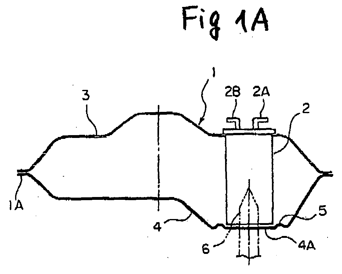
- Fig. 1A is a sectional view of a fuel tank
- Fig. 1B is a plane view of a display portion of a working position
- Fig. 1C is a sectional view of the working position display portion
- Fig. 2 is a perspective view of the fuel tank.
- Fig. 1A is a sectional view of a fuel tank
- Fig. 1B is a plane view of a display portion of a working position
- Fig. 1C is a sectional view of the working position display portion
- Fig. 2 is a perspective view of the fuel tank.
- Fig. 1A is a sectional view of a fuel tank
- Fig. 1B is a plane view of a display portion of a working position
- Fig. 1C is a sectional view of the working position display portion
- Fig. 2 is a perspective view of the fuel tank.
- a basic structure of a fuel tank structure of the present invention comprises an upper member 3, a lower member 4, and a display portion 5 of a working position of a waste fuel hole provided at an outer surface (which is a bottom portion at the lowest position and preferably a position of a chamber module 2) of the lower member 4.
- the first embodiment is applied to the fuel tank of a normal type formed with a single one of a bottom portion 4Ahaving the lowest position.
- a fuel tank 1 is made by connecting the upper member 3 and the lower member 4 respectively having different shapes and molded by separate steps by welding or the like at an abutting peripheral edge 1A.
- a bead portion 5 is formed at the bottom portion 4A constituting the lowest position in the lower member 4.
- the bead portion 5 is formed by projecting a predetermined amount t to an inner side of the fuel tank to constitute a display function and ensure a rigidity and prevent the display function from being deteriorated even by coating an undercoat.
- the bead portion 5 is formed in a shape of a divided ring 'as shown by Fig. 1B.
- the bead portion 5 has a first bead portion 5A, a second bead portion 5B and a third bead portion 5C in a mode indicated by arrow marks divided in three (indicating a recycle). Therefore, cut portions 7 are formed among the respective bead portions 5A, 5B, 5C.
- a lower end portion of the chamber module 2 installed at the upper member 3 and containing a fuel pump or the like is aligned and set to a proper position to the ring-shaped bead portion 5.
- a predetermined clearance is set between a lower surface of the chamber module 2 and the lower member 4.
- reference number 2A in Fig. 1A designates a fuel pipe for supplying the fuel to an engine and a reference number 2B designates a vent pipe connected to a vent line.
- the fuel at an inside of the fuel tank 1 is introduced to the fuel pump, not illustrated, via a side wall, a hole of the lower surface of the chamber module 2, and supplied to the engine via the fuel pipe 2A and a high pressure gas due to a high temperature at the inside of the fuel tank 1 is introduced to a canister or the like at the vent line via the vent pipe 2B.
- the display portion 5 of the working position for specifying / clearly indicating at least a position of the outer surface of the bottom portion 4A at the lowest position of the lower member 4 in correspondence with the fuel remaining portion, preferably, a position of the chamber module 2 (arranged with one way valve or the like other than a fuel pump and the remaining fuel is difficult to be discharged). Therefore, operation of boring (or drilling) a waste fuel hole by a spearhead-shaped drill 6 may be carried out as shown by chain lines of Fig. 1A.
- the bottom portion 4A to be bored can be ensured with a predetermined rigidity and the boring operation can firmly be carried out.
- the fuel can be drained out via the waste fuel hole from the bottom portion of the chamber module 2 at which the remaining fuel is liable to be stored.
- the remaining fuel stored to the bottom portion 4A on an outer side of the bead portion 5 is made to flow to the waste fuel hole via the cut portions 7 among the respective bead portions 5A, 5B, 5C structured to divide and the remaining fuel can firmly be drained out.
- the working position display portion 5 is formed to project to inside of the fuel tank 1 by the predetermined amount t, the working position display portion 5 is formed to surround the chamber module 2. Therefore, the chamber module 2 is not hampered (or prevented) frombeing arranged at a vicinity of the lower surface of the fuel tank 1.
- Fig. 3 shows a second embodiment of the fuel tank structure according to the present invention
- Fig. 3A is the entire sectional view of a fuel tank
- Fig. 3B is a plane view of a display portion of a working position.
- the second embodiment is an example of being applied to a saddle type tank capable of ensuring a predetermined effective remaining amount of a fuel.
- the fuel tank 1 of the second embodiment shows a saddle type section in which the bottom portion of the lower member 4 includes two bottom portions of a first bottom portion 4A and a second bottom portion 4B.
- the predetermined effective remaining amount can be ensured on the second bottom portion 4B. Therefore, in emergency, the remaining fuel on the second bottom portion 4B can be sucked (or drawn) by a fuel pump or the like to supply to a combustion chamber by a switching cock or the like.
- the working position display portion 5 for the waste fuel hole is formed at the lowest portion of the second bottom portion 4B of the lower member 4 in correspondence with the fuel remaining portion.
- a bead portion formed by proj ecting a predetermined amount thereof to the inner side of the fuel tank.
- the structure of the chamber module 2 and the beadportion 5 of the display portion on the first bottom portion 4A is similar to that of the above-described first embodiment and therefore, an explanation thereof will be omitted.
- the waste fuel hole can be recognized and the boring operation can easily be carried out for draining out the remaining fuel.
- the shape of the fuel tank (a pertinent divided mode can be adopted other than the mode of dividing the upper member and the lower member upwardly and downwardly. Further, a structure relating to a main portion and the bottom portion of the tank can pertinently be adopted.), the type of the fuel tank (having a single one of the bottom portion, the saddle type having the two bottom portions or the like), the shape of the display portion of the waste fuel hole (other than the three arrow marks signifying the recycle in the bead shape projected to the inner side of the tank, a pertinent shape provided with cut portions can be adopted.
- a continuous bead portion can be structured without being divided), further, when it is not necessary to take into account the rigidity in the boring operation, the display portion may not be structured by the projected bead portion) and the like.
- the display portion of the waste fuel hole may be provided on the outer surface at a portion at which the fuel at inside of the fuel tank is liable to remain in accordance with the shape of the fuel tank, the position of the fuel pump or the like also at other than right below the chamber module or the bottom portion of the fuel tank.
- the shape of the chamber module (a square cylindrical shape, a spherical shape or the like other than the circular cylindrical shape), the type (the method of arranging the fuel pump and the one way vale or the like), the structure related to the display portion of the bead portion or the like (other than being positioned as dimensions of respective portions such that the chamber module is matched to the inner side of the ring-shaped bead portion without excess and deficiency, or after setting to position the lower end edge of the chamber module by being guided by an inclined face of the bead portion, the bead portion is arranged at the surrounding of the chamber module with more or less allowance), the amount of projecting the bead portion as the display portion, a mode of catching the fuel drained out via the waste fuel hole and the like.
- the working position display portion of the waste fuel hole at the outer surface in correspondence with the fuel remaining portion, the position of the portion at which the remaining fuel is liable to remain can clearly be recognized and the boring operation of the waste fuel hole by the spearhead-shaped drill or the like can easily be carried out.
- the display portion when the display portion is installed in the mode right below the chamber module arranged at an inside of the fuel tank and surrounding the surrounding of the chamber module, the position of the chamber module at which the remaining fuel is liable to remain can easily be recognized from outside and the boring operation of the waste fuel hole along with the chamber module can easily be carried out by the spearhead-shaped drill or the like.
- the working position display portion is the bead portion formed by projecting the predetermined amount to the inner side of the fuel tank
- the bead portion can be utilized as the positioning member in attaching the chamber module or the like to the fuel tank, the boring operation can firmly and securely be carried out by ensuring the predetermined rigidity at the bottom portion to be bored and the fuel can be drained out from the bottom portion of the chamber module at which the remaining fuel is liable to be stored via the waste fuel hole.
- the bead portion is characterized by being structured by the plurality of noncontinuous bead portions
- the remaining fuel stored to the bottom portion on the outer side of the bead portion is also made to flow to the waste fuel hole via the cut portions among the noncontinuous bead portions and the remaining fuel can firmly be drained out.
- the fuel tank structure capable of draining out the total amount of the fuel by boring the fuel draining hole at the optimum position firmly and easily under the high rigidity without a special facility.
Landscapes
- Engineering & Computer Science (AREA)
- Life Sciences & Earth Sciences (AREA)
- Sustainable Development (AREA)
- Sustainable Energy (AREA)
- Chemical & Material Sciences (AREA)
- Combustion & Propulsion (AREA)
- Transportation (AREA)
- Mechanical Engineering (AREA)
- Cooling, Air Intake And Gas Exhaust, And Fuel Tank Arrangements In Propulsion Units (AREA)
Abstract

Description
Claims (8)
- A fuel tank structure, comprising:a display portion of a working position of a waste fuel hole provided at an outer surface of a fuel tank in correspondence with a fuel remaining portion.
- The fuel tank structure according to Claim 1, wherein: the display portion is installed in a state that the display portion is placed right below a chamber module arranged at inside of a fuel tank and surrounds the chamber module.
- The fuel tank structure according to Claim 1, wherein: the display position is a bead portion formed by projecting a predetermined amount of the bead portion to an inner side of the fuel tank.
- The fuel tank structure according to Claim 2, wherein: the display position is a bead portion formed by projecting a predetermined amount of the bead portion to an inner side of the fuel tank.
- The fuel tank structure according to Claim 3, wherein: the beadportion includes a plurality of noncontinuous bead portions.
- The fuel tank structure according to Claim 4, wherein: the bead portion includes a plurality of noncontinuous bead portions.
- The fuel tank structure according to Claim 3, wherein: the bead portion includes the plurality of the bead portions and cut portions formed among the respective bead portions.
- The fuel tank structure according to Claim 4, wherein: the bead portion includes the plurality of the bead portions and cut portions formed among the respective bead portions.
Applications Claiming Priority (2)
| Application Number | Priority Date | Filing Date | Title |
|---|---|---|---|
| JP2003098913 | 2003-04-02 | ||
| JP2003098913A JP4176534B2 (en) | 2003-04-02 | 2003-04-02 | Fuel tank structure |
Publications (3)
| Publication Number | Publication Date |
|---|---|
| EP1470945A2 true EP1470945A2 (en) | 2004-10-27 |
| EP1470945A3 EP1470945A3 (en) | 2007-06-13 |
| EP1470945B1 EP1470945B1 (en) | 2009-09-16 |
Family
ID=32959556
Family Applications (1)
| Application Number | Title | Priority Date | Filing Date |
|---|---|---|---|
| EP04007851A Expired - Lifetime EP1470945B1 (en) | 2003-04-02 | 2004-03-31 | Fuel tank structure |
Country Status (4)
| Country | Link |
|---|---|
| US (1) | US7516868B2 (en) |
| EP (1) | EP1470945B1 (en) |
| JP (1) | JP4176534B2 (en) |
| DE (1) | DE602004023149D1 (en) |
Families Citing this family (11)
| Publication number | Priority date | Publication date | Assignee | Title |
|---|---|---|---|---|
| ATE410326T1 (en) * | 2003-11-07 | 2008-10-15 | Inergy Automotive Systems Res | FUEL SYSTEM FOR AN COMBUSTION ENGINE |
| JP2008013245A (en) * | 2006-07-10 | 2008-01-24 | Nissan Motor Co Ltd | TANK MANUFACTURING METHOD AND TANK USING THE METHOD |
| JP5018302B2 (en) * | 2007-07-13 | 2012-09-05 | トヨタ自動車株式会社 | Fuel tank insulator |
| DE102008009829A1 (en) * | 2008-02-18 | 2009-08-27 | Kautex Textron Gmbh & Co. Kg | Fuel tank for motor vehicles, of thermoplastic |
| US8448295B2 (en) * | 2010-03-12 | 2013-05-28 | Electrolux Home Care Products, Inc. | Vacuum cleaner with rotating handle |
| US8596249B2 (en) * | 2010-06-15 | 2013-12-03 | Ford Global Technologies, Llc | Fuel delivery module reinforced fuel tank |
| JP6237014B2 (en) * | 2013-09-06 | 2017-11-29 | 三菱自動車工業株式会社 | Vehicle fuel tank |
| CN106523216B (en) * | 2016-11-11 | 2019-03-15 | 江苏理工学院 | A system for recovering residual fuel in a scrapped automobile fuel tank and its working method |
| CN107985454A (en) * | 2017-11-09 | 2018-05-04 | 成都兴原再生资源投资有限公司 | A kind of abandoned car fluid recycles perforator |
| CN110562359B (en) * | 2019-08-27 | 2021-05-18 | 武汉格林美城市矿产装备有限公司 | Portable drilling liquid extractor |
| CN111618068B (en) * | 2020-05-19 | 2022-02-11 | 南京信息职业技术学院 | Electric Spiral Cone Rod Squeeze and Pull Oil Tank Drain Hole Equipment |
Family Cites Families (21)
| Publication number | Priority date | Publication date | Assignee | Title |
|---|---|---|---|---|
| US2208621A (en) * | 1937-09-20 | 1940-07-23 | Chrysler Corp | Fuel tank |
| JPS5240690B2 (en) | 1973-12-08 | 1977-10-13 | ||
| JPS5855213B2 (en) | 1980-03-31 | 1983-12-08 | 電気興業株式会社 | Method and device for heat treatment of threaded parts using high-frequency induction heating |
| US4638836A (en) * | 1985-04-26 | 1987-01-27 | Ford Motor Company | Motor vehicle fuel tank with unitary fuel reservoir |
| US5221021A (en) * | 1991-12-16 | 1993-06-22 | Ford Motor Company | Fuel tank reservoir |
| DE9207313U1 (en) * | 1992-05-29 | 1992-09-17 | Aichinger jun., Josef, 8201 Raubling | Device for disposing of fuel |
| JPH1018929A (en) | 1996-06-28 | 1998-01-20 | Jidosha Recycle Res Center:Kk | Fuel extracting device |
| JPH10230822A (en) | 1997-02-21 | 1998-09-02 | Jgc Corp | Disposal facility and disposal of used car |
| US5931353A (en) * | 1997-04-28 | 1999-08-03 | Solvay (Societe Anonyme) | Plastic hollow body with internal fastening arrangement |
| US5951050A (en) * | 1997-09-18 | 1999-09-14 | Siekmann; Jim | Integral reservoir for tank |
| DE19849820A1 (en) * | 1998-10-29 | 2000-05-11 | Kautex Textron Gmbh & Co Kg | Fuel tank system for a motor vehicle |
| JP2000141295A (en) | 1998-11-06 | 2000-05-23 | Jidosha Recycle Research Center:Kk | Drilling tool for draining waste vehicles |
| US6135306A (en) * | 1999-02-08 | 2000-10-24 | Salflex Polymers Inc. | Fuel tank anti-deflection device |
| US6298540B1 (en) * | 2000-09-28 | 2001-10-09 | Eaton Corporation | Combined fuel pump, level sender and rollover venting valve for a fuel tank |
| DE10054876C2 (en) * | 2000-11-06 | 2002-11-07 | Sig Kautex Gmbh & Co Kg | Double-walled fuel tank made of plastic |
| US6371153B1 (en) * | 2001-03-16 | 2002-04-16 | Robert Bosch Corporation | Dual fuel delivery module system for multi-chambered or multiple automotive fuel tanks |
| DE10135328A1 (en) * | 2001-07-19 | 2003-02-13 | Daimler Chrysler Ag | Container for motor fuel, and other hazardous liquids, has an outflow structure at its deepest point as a projecting nipple, with a one-piece closure to be removed when required |
| US6669043B2 (en) * | 2001-09-27 | 2003-12-30 | Visteon Global Technologies, Inc. | Passthru device for internalized component fuel tanks |
| JP2003118403A (en) * | 2001-10-17 | 2003-04-23 | Toyota Motor Corp | Fuel tank |
| FR2839957B1 (en) * | 2002-05-24 | 2004-08-20 | Ets Magyar | REINFORCED TANK |
| JP4346283B2 (en) * | 2002-06-05 | 2009-10-21 | 日産自動車株式会社 | Fuel tank |
-
2003
- 2003-04-02 JP JP2003098913A patent/JP4176534B2/en not_active Expired - Fee Related
-
2004
- 2004-03-31 EP EP04007851A patent/EP1470945B1/en not_active Expired - Lifetime
- 2004-03-31 DE DE602004023149T patent/DE602004023149D1/en not_active Expired - Lifetime
- 2004-03-31 US US10/813,054 patent/US7516868B2/en not_active Expired - Fee Related
Also Published As
| Publication number | Publication date |
|---|---|
| EP1470945B1 (en) | 2009-09-16 |
| JP2004308435A (en) | 2004-11-04 |
| JP4176534B2 (en) | 2008-11-05 |
| EP1470945A3 (en) | 2007-06-13 |
| US20040195247A1 (en) | 2004-10-07 |
| DE602004023149D1 (en) | 2009-10-29 |
| US7516868B2 (en) | 2009-04-14 |
Similar Documents
| Publication | Publication Date | Title |
|---|---|---|
| EP1470945B1 (en) | Fuel tank structure | |
| US5257652A (en) | Fluid collection system for installation underground and method of installation | |
| EP1320468B1 (en) | Installing of a combined fuel pump, level sender and rollover venting valve in a fuel tank | |
| JP4722402B2 (en) | Fuel pump module, its manufacturing method and fuel delivery system | |
| US5078233A (en) | Oil supply system for machines such as internal combustion engines | |
| EP1212560B1 (en) | Valve and method for fitting it to a tank | |
| US8464764B1 (en) | Fuel system ullage float assembly | |
| US20090071543A1 (en) | Fuel Vent Valve And Improvement Thereof | |
| US5327861A (en) | Automatic oil additive injector | |
| US6523581B2 (en) | Apparatus and method for minimizing vapor loss | |
| US9981546B2 (en) | Valve device for fuel tank | |
| EP1314603A1 (en) | Low permeation cam lock for plastic fuel tank vapor vent valve | |
| EP3599121A1 (en) | Valve device for fuel tank | |
| US5706857A (en) | Fuel tank vent value and probe assembly | |
| US12280657B2 (en) | Pressure relief assembly and a valve assembly that uses the pressure relief assembly | |
| US10953742B2 (en) | Fuel tank | |
| KR20000010795A (en) | Fuel supply device | |
| US6510867B2 (en) | Pressure relief valve | |
| KR101062894B1 (en) | Indicator for oil drain valve | |
| US20050115608A1 (en) | Oil deaeration device | |
| US6726185B1 (en) | Rollover valve for carburetor float bowls | |
| JPH09286247A (en) | Fuel storage | |
| AU726581B2 (en) | Vent assembly | |
| KR102392799B1 (en) | Cut-off shaft lifting apparatus for ship gas injection valve inspection equipment | |
| US2284709A (en) | Safety apparatus |
Legal Events
| Date | Code | Title | Description |
|---|---|---|---|
| PUAI | Public reference made under article 153(3) epc to a published international application that has entered the european phase |
Free format text: ORIGINAL CODE: 0009012 |
|
| AK | Designated contracting states |
Kind code of ref document: A2 Designated state(s): AT BE BG CH CY CZ DE DK EE ES FI FR GB GR HU IE IT LI LU MC NL PL PT RO SE SI SK TR |
|
| AX | Request for extension of the european patent |
Extension state: AL LT LV MK |
|
| PUAL | Search report despatched |
Free format text: ORIGINAL CODE: 0009013 |
|
| AK | Designated contracting states |
Kind code of ref document: A3 Designated state(s): AT BE BG CH CY CZ DE DK EE ES FI FR GB GR HU IE IT LI LU MC NL PL PT RO SE SI SK TR |
|
| AX | Request for extension of the european patent |
Extension state: AL LT LV MK |
|
| 17P | Request for examination filed |
Effective date: 20071130 |
|
| AKX | Designation fees paid |
Designated state(s): DE FR |
|
| 17Q | First examination report despatched |
Effective date: 20080207 |
|
| GRAP | Despatch of communication of intention to grant a patent |
Free format text: ORIGINAL CODE: EPIDOSNIGR1 |
|
| GRAJ | Information related to disapproval of communication of intention to grant by the applicant or resumption of examination proceedings by the epo deleted |
Free format text: ORIGINAL CODE: EPIDOSDIGR1 |
|
| GRAP | Despatch of communication of intention to grant a patent |
Free format text: ORIGINAL CODE: EPIDOSNIGR1 |
|
| GRAS | Grant fee paid |
Free format text: ORIGINAL CODE: EPIDOSNIGR3 |
|
| GRAA | (expected) grant |
Free format text: ORIGINAL CODE: 0009210 |
|
| AK | Designated contracting states |
Kind code of ref document: B1 Designated state(s): DE FR |
|
| REF | Corresponds to: |
Ref document number: 602004023149 Country of ref document: DE Date of ref document: 20091029 Kind code of ref document: P |
|
| PGFP | Annual fee paid to national office [announced via postgrant information from national office to epo] |
Ref country code: FR Payment date: 20100303 Year of fee payment: 7 |
|
| PLBE | No opposition filed within time limit |
Free format text: ORIGINAL CODE: 0009261 |
|
| STAA | Information on the status of an ep patent application or granted ep patent |
Free format text: STATUS: NO OPPOSITION FILED WITHIN TIME LIMIT |
|
| 26N | No opposition filed |
Effective date: 20100617 |
|
| REG | Reference to a national code |
Ref country code: FR Ref legal event code: ST Effective date: 20111130 |
|
| PG25 | Lapsed in a contracting state [announced via postgrant information from national office to epo] |
Ref country code: FR Free format text: LAPSE BECAUSE OF NON-PAYMENT OF DUE FEES Effective date: 20110331 |
|
| REG | Reference to a national code |
Ref country code: DE Ref legal event code: R082 Ref document number: 602004023149 Country of ref document: DE Representative=s name: VOSSIUS & PARTNER PATENTANWAELTE RECHTSANWAELT, DE Ref country code: DE Ref legal event code: R081 Ref document number: 602004023149 Country of ref document: DE Owner name: SUBARU CORPORATION, JP Free format text: FORMER OWNER: FUJI JUKOGYO K.K., TOKIO/TOKYO, JP |
|
| PGFP | Annual fee paid to national office [announced via postgrant information from national office to epo] |
Ref country code: DE Payment date: 20180320 Year of fee payment: 15 |
|
| REG | Reference to a national code |
Ref country code: DE Ref legal event code: R119 Ref document number: 602004023149 Country of ref document: DE |
|
| PG25 | Lapsed in a contracting state [announced via postgrant information from national office to epo] |
Ref country code: DE Free format text: LAPSE BECAUSE OF NON-PAYMENT OF DUE FEES Effective date: 20191001 |