EP1470546B1 - Method and apparatus for focussing ultrasonic energy - Google Patents
Method and apparatus for focussing ultrasonic energy Download PDFInfo
- Publication number
- EP1470546B1 EP1470546B1 EP03702710.9A EP03702710A EP1470546B1 EP 1470546 B1 EP1470546 B1 EP 1470546B1 EP 03702710 A EP03702710 A EP 03702710A EP 1470546 B1 EP1470546 B1 EP 1470546B1
- Authority
- EP
- European Patent Office
- Prior art keywords
- lens
- region
- focussing
- radius
- substantially annular
- Prior art date
- Legal status (The legal status is an assumption and is not a legal conclusion. Google has not performed a legal analysis and makes no representation as to the accuracy of the status listed.)
- Expired - Lifetime
Links
- 238000000034 method Methods 0.000 title description 13
- 239000000463 material Substances 0.000 claims description 18
- XAGFODPZIPBFFR-UHFFFAOYSA-N aluminium Chemical compound [Al] XAGFODPZIPBFFR-UHFFFAOYSA-N 0.000 claims description 8
- 239000004411 aluminium Substances 0.000 claims description 7
- 229910052782 aluminium Inorganic materials 0.000 claims description 7
- 239000000203 mixture Substances 0.000 claims description 4
- 229910000838 Al alloy Inorganic materials 0.000 claims description 3
- 229910001069 Ti alloy Inorganic materials 0.000 claims description 3
- RTAQQCXQSZGOHL-UHFFFAOYSA-N Titanium Chemical compound [Ti] RTAQQCXQSZGOHL-UHFFFAOYSA-N 0.000 claims description 2
- 239000010936 titanium Substances 0.000 claims description 2
- 229910052719 titanium Inorganic materials 0.000 claims description 2
- 230000005540 biological transmission Effects 0.000 description 13
- 210000001519 tissue Anatomy 0.000 description 11
- 239000000919 ceramic Substances 0.000 description 7
- 238000011282 treatment Methods 0.000 description 7
- ZIBGPFATKBEMQZ-UHFFFAOYSA-N triethylene glycol Chemical compound OCCOCCOCCO ZIBGPFATKBEMQZ-UHFFFAOYSA-N 0.000 description 6
- 238000002604 ultrasonography Methods 0.000 description 6
- 239000013078 crystal Substances 0.000 description 4
- 210000004207 dermis Anatomy 0.000 description 4
- 230000000694 effects Effects 0.000 description 4
- 239000012528 membrane Substances 0.000 description 4
- 229910052751 metal Inorganic materials 0.000 description 4
- 239000002184 metal Substances 0.000 description 4
- XLYOFNOQVPJJNP-UHFFFAOYSA-N water Substances O XLYOFNOQVPJJNP-UHFFFAOYSA-N 0.000 description 4
- 239000011358 absorbing material Substances 0.000 description 3
- 210000004204 blood vessel Anatomy 0.000 description 3
- 230000007423 decrease Effects 0.000 description 3
- 239000012530 fluid Substances 0.000 description 3
- 210000004185 liver Anatomy 0.000 description 3
- 238000005259 measurement Methods 0.000 description 3
- 230000003287 optical effect Effects 0.000 description 3
- 210000003491 skin Anatomy 0.000 description 3
- 210000003462 vein Anatomy 0.000 description 3
- 206010028980 Neoplasm Diseases 0.000 description 2
- 238000010521 absorption reaction Methods 0.000 description 2
- 238000013459 approach Methods 0.000 description 2
- 210000001367 artery Anatomy 0.000 description 2
- 230000008901 benefit Effects 0.000 description 2
- 238000013461 design Methods 0.000 description 2
- 229920006332 epoxy adhesive Polymers 0.000 description 2
- 238000011835 investigation Methods 0.000 description 2
- 230000007246 mechanism Effects 0.000 description 2
- 206010033675 panniculitis Diseases 0.000 description 2
- 230000008569 process Effects 0.000 description 2
- 230000009467 reduction Effects 0.000 description 2
- 210000004304 subcutaneous tissue Anatomy 0.000 description 2
- 238000001356 surgical procedure Methods 0.000 description 2
- 229920003319 Araldite® Polymers 0.000 description 1
- 102000008186 Collagen Human genes 0.000 description 1
- 108010035532 Collagen Proteins 0.000 description 1
- 239000004593 Epoxy Substances 0.000 description 1
- 229910000556 Monel K-500 Inorganic materials 0.000 description 1
- 208000000453 Skin Neoplasms Diseases 0.000 description 1
- 239000000853 adhesive Substances 0.000 description 1
- 230000001070 adhesive effect Effects 0.000 description 1
- PNEYBMLMFCGWSK-UHFFFAOYSA-N aluminium oxide Inorganic materials [O-2].[O-2].[O-2].[Al+3].[Al+3] PNEYBMLMFCGWSK-UHFFFAOYSA-N 0.000 description 1
- 230000003321 amplification Effects 0.000 description 1
- 238000004458 analytical method Methods 0.000 description 1
- 229940030225 antihemorrhagics Drugs 0.000 description 1
- 238000003491 array Methods 0.000 description 1
- 230000036770 blood supply Effects 0.000 description 1
- 238000004364 calculation method Methods 0.000 description 1
- 201000011510 cancer Diseases 0.000 description 1
- 239000004568 cement Substances 0.000 description 1
- 229920001436 collagen Polymers 0.000 description 1
- 239000002131 composite material Substances 0.000 description 1
- 238000010276 construction Methods 0.000 description 1
- 239000002537 cosmetic Substances 0.000 description 1
- 230000008878 coupling Effects 0.000 description 1
- 238000010168 coupling process Methods 0.000 description 1
- 238000005859 coupling reaction Methods 0.000 description 1
- 238000005520 cutting process Methods 0.000 description 1
- 230000001419 dependent effect Effects 0.000 description 1
- 230000035617 depilation Effects 0.000 description 1
- 230000001066 destructive effect Effects 0.000 description 1
- 238000006073 displacement reaction Methods 0.000 description 1
- 238000005868 electrolysis reaction Methods 0.000 description 1
- 238000002474 experimental method Methods 0.000 description 1
- 230000005669 field effect Effects 0.000 description 1
- 230000000025 haemostatic effect Effects 0.000 description 1
- 239000000314 lubricant Substances 0.000 description 1
- 238000003754 machining Methods 0.000 description 1
- 238000004519 manufacturing process Methods 0.000 description 1
- 201000001441 melanoma Diseases 0.000 description 1
- 238000003199 nucleic acid amplification method Methods 0.000 description 1
- 230000010363 phase shift Effects 0.000 description 1
- 239000004810 polytetrafluoroethylene Substances 0.000 description 1
- 229920001343 polytetrafluoroethylene Polymers 0.000 description 1
- 230000001902 propagating effect Effects 0.000 description 1
- 238000011084 recovery Methods 0.000 description 1
- 239000007787 solid Substances 0.000 description 1
- 239000011343 solid material Substances 0.000 description 1
- 239000010935 stainless steel Substances 0.000 description 1
- 229910001220 stainless steel Inorganic materials 0.000 description 1
- 238000007920 subcutaneous administration Methods 0.000 description 1
- 239000013077 target material Substances 0.000 description 1
- 208000009056 telangiectasis Diseases 0.000 description 1
- 238000012360 testing method Methods 0.000 description 1
- 238000012546 transfer Methods 0.000 description 1
- 230000002792 vascular Effects 0.000 description 1
- 230000000007 visual effect Effects 0.000 description 1
- 238000004018 waxing Methods 0.000 description 1
Images



Classifications
-
- G—PHYSICS
- G10—MUSICAL INSTRUMENTS; ACOUSTICS
- G10K—SOUND-PRODUCING DEVICES; METHODS OR DEVICES FOR PROTECTING AGAINST, OR FOR DAMPING, NOISE OR OTHER ACOUSTIC WAVES IN GENERAL; ACOUSTICS NOT OTHERWISE PROVIDED FOR
- G10K11/00—Methods or devices for transmitting, conducting or directing sound in general; Methods or devices for protecting against, or for damping, noise or other acoustic waves in general
- G10K11/18—Methods or devices for transmitting, conducting or directing sound
- G10K11/26—Sound-focusing or directing, e.g. scanning
- G10K11/30—Sound-focusing or directing, e.g. scanning using refraction, e.g. acoustic lenses
Definitions
- the present invention relates to a method and apparatus for focussing ultrasonic energy.
- the apparatus and method may be used, inter alia , for treatment of tissue, especially subcutaneous tissue, utilising non-invasive focussed ultrasound.
- a light beam is focussed by a lens so that a planar beam of light is directed to a point of convergence (and subsequent divergence). In this case the lens is not affected by the electromagnetic beam as it travels through the device.
- Ultrasound is generated by a vibrating device. If the device is a curved piezo-electric transducer crystal then the curved surface of the crystal emits a sound wave propagating normally to the surface. This wave converges over a common region.
- the essential difference between the optical and the ultrasonic is that the distance of the point of convergence of the sound wave from the "lens" is dependent upon the mode of resonance in the vibrating device.
- the case of a curved piezoelectric ceramic transducer (PZT) crystal is relatively simple, since essentially only a single mode of resonance should be possible.
- a piezo ceramic generator and a focussing element may be deliberately close-coupled, using some form of epoxy or other cement.
- the simple theory is inadequate to predict focal plane position and beam intensities. Errors of up to 50% are apparent when determining the properties of small diameter acoustic lenses.
- a disc PZT is bonded to a disc of metal to produce a combination transducer, then multiple modes of resonance become possible, and the effects of changes in mode are extremely complex.
- the free face of the metal disc is given a convex radius then most modes of resonance result in a radiating beam, i.e. divergent.
- the transmission path of the "beam" will reduce in diameter, before subsequently increasing. This convergence will vary with the mode of resonance in degree, in the minimum diameter of the transmission path attained, and in its position from the lens.
- Finite element techniques can accurately model complex physical systems which consist of two or more solid materials and an essentially fluid phase representing a target material. If it is possible to determine the transducer/lens geometry to achieve particular focussing characteristics, it will greatly simplify the task of designing and building focussed arrays of transducers with combined lens systems.
- the finite element model may be used to predict the geometry of axisymmetric lens transducer combinations taking into account all factors affecting the vibrational modes generated in the solid components of the system.
- the analytical mesh may be extended into the fluid phase to generate beam shape and confirm the focussing characteristics of the device.
- Curved PZT transmitters (operating in the MHz bands) are used in various medical applications, but they suffer from at least two inherent limitations. They are expensive to produce and they are essentially fragile.
- the former problem is simply a function of the production process.
- the latter arises from the high output requirements for medical applications and the minimal thickness of the ceramic in order to achieve resonance at MHz frequencies.
- Combination transducers i.e. transducers having a lens firmly attached to the PZT, should point towards a single solution to these problems.
- flat disc PZTs are a fraction of the cost of curved ceramics, and may be produced in all possible dimensions.
- bonding a flat PZT to an aluminium plate, using epoxy adhesive results in a highly durable system.
- Such combination transducers can be further improved by curving a face of the lens plate. See, for example, US 3903990 .
- the focussing of such transducers is much more complex than has hitherto been thought.
- tissue which may be treated by the method and using the apparatus includes subcutaneous blood vessels, unsightly thread veins, selected cancer tissue, and the like.
- the apparatus may be used for haemostatic cutting and cauterising of blood vessels. It may also be used in other, non-medical, areas where it is desired to apply high intensity energy to a small target zone.
- tissue type which may benefit from such treatment comprises fine arteries and veins lying closely beneath the dermis. These may become visible in quite random areas, and where they are visible through the dermis in a localised area, these arteries or veins may constitute a serious visual skin blemish, known sometimes as "spider veins.”
- cancerous cell may lie close beneath the surface, such as skin cancers and other melanomas.
- Such cancers can sometimes be treated by means of laser irradiation, but there may again be damage to surrounding tissue and to the outer layers of the dermis and this may be unacceptable.
- Cosmetic skin treatments may also be carried out in similar ways.
- Collagen molecules may be restructured in order to tighten and restructure skin tissue, using a focussed beam.
- Depilation may presently be carried out by painful treatments such as electrolysis, or temporarily by waxing, shaving or plucking. A beam of energy focussed on each follicle would destroy the hair and prevent further growth.
- a focussed beam may also be used to destroy dyed tissue and thereby aid removal of unwanted tattoos.
- an apparatus for focussing a beam of ultrasonic vibration comprising means to generate ultrasonic vibrations and lens means affixed to said generating means and adapted to focus said ultrasonic vibration at a predetermined zone, wherein the lens means is divided into a series of concentrically-arranged annular regions, each of which comprises material having a wave velocity substantially different from that of adjacent regions.
- the wave velocities of said series of substantially annular regions vary sequentially between an innermost region and an outermost said region.
- said wave velocities rise sequentially between an innermost region and an outermost region.
- the lens means may be plano-concave.
- the lens means may comprise titanium, titanium alloy, aluminium, aluminium alloy, or a mixture containing such materials.
- Each said substantially annular region may be separated from adjacent regions by an isolating material.
- the lens means may be divided into a series of substantially annular zones each of material having a different wave velocity.
- the apparatus may be applied to treatment of a zone of tissue on or beneath the dermis.
- a piezoelectric ceramic disc 1 is adapted to produce high frequency ultrasound in the 1 - 5 MHz range when excited at an appropriate frequency by electrical means (not shown).
- a focusing plano-concave lens 2 of aluminium alloy, titanium alloy or other suitable material or mixture, whereby the ultrasonic vibration is directed to a focal zone 3 within the body wherein is located tissue to be treated.
- a single piezoelectric ceramic transducer preferably of diameter 35mm, is attached to a complex lens 5, of thickness preferably 12-13mm at its periphery and in the region of 8mm at its thinnest point.
- the outer surface of the lens 5 is formed to have four equiangularly spaced concavities 6. Each forms part of a sphere, with the radii of curvature meeting at a preselected point.
- More or less than four concavities 6 may be provided.
- the beam cross section determined experimentally closely matches the theoretically predicted pattern.
- the hydrophone is accurately positioned relative to the transmitter, in three dimensions, using Vernier drives.
- the sensor measures the pressure developed by the travelling wave passing through the water, and converts this into a voltage signal; this is then plotted on a PC to produce a record of the transmission path shape.
- the width of the transmission path can be measured at known distances from the centre of the lens, allowing the calculation of the position of the minimum width, i.e. the "focal point”; and the degree of "focus", the ratio of lens surface area, and area of the transmission path at the "focal” plane.
- the material used for the lens was aluminium, for the ease of machining and good acoustic properties, and for the bond - standard Araldite (RTM) epoxy adhesive.
- the smallest radius of curvature was derived by taking the half-wavelength at 1 MHz in aluminium (which is ⁇ 2.5mm) and making this the depth of the concave surface. This meant that if the minimum thickness was also 2.5mm, then theoretically the greatest amplitude at the lens surface would be shown both at the centre and extremity of the surface.
- the radius of 6.25mm was simply the result of fixing these dimensions.
- the first point to note is the small values obtained for Acoustic Output. This is due to two factors. Firstly, the crystals are "tuned” to a natural frequency of 1MHz, thus the modes of resonance giving required characteristics are "off-resonance", insofar as they are not at the natural resonant frequency of the systems. This results in poor energy transfer from the generator. Consequently, the generator should be optimised for the loads specific electrical characteristics, allowing modes of resonance not at the natural resonant frequency to be efficiently driven.
- the levels of "focus” measured are of the order needed to reach the intensities required to achieve denaturing in mammalian tissue. This achievement was the initial requirement to move on to identify the levels of Heat Generator in samples of "model” absorbing material.
- the experimental technique and principal of the set-up is quite simple.
- the transmitter being assessed is inserted into a lower holding tube, to a known depth. Water is injected into the space between the lens and the membrane covering the tube, all air being removed via a second tube/syringe.
- the upper portion of the system is mounted against the lower.
- the sample holder, containing the chosen absorbing material held in by a second membrane, is screwed down to the required height. Acoustic coupling gel acts as a lubricant between the two membranes and limits losses.
- the thermocouple holder is inserted into the top of the sample holder to measure initial temperature, it is then removed, the transducer activated for a fixed time, and the thermocouple re-introduced to measure the temperature rise due to the insonation. (Ambient temperature is simultaneously monitored as a control).
- TEG is an excellent test material for assessment of Acoustic Absorption.
- the propagation of wave energy from all parts of the concave output face should be directed substantially towards the generator axis, and each surface element of the concave radiating face should experience a displacement which is substantially in-phase with all neighbouring elements, in both circumferential and radial directions.
- plano-concave lens comprises a plurality of annular sections (B,C, D, E) surrounding a central circular section (A).
- Each section is of a material having complimenting properties so that the wave from the planar face, contacting the PZT disc, will be transmitted from the concave radiating face 8 in an optimum manner.
- the device shown in Figures 4A and 4B has concentric sections A, B, C, D and E, consisting of different materials each displaying an appropriate phase velocity constant, and separated by tubes 7 of an isolating material, for example PTFE.
- the elements of the concave, radiating surface 8 are adapted to meet the above criteria, i.e. with in-phase convergent waves transmitting from surface 8.
- Table 6, below shows by way of example materials and thei arrangement to give increasing phase velocity from the inner to the outer elements to compensate for the increase in thickness across the lens.
- Table 6 shows by way of example materials and thei arrangement to give increasing phase velocity from the inner to the outer elements to compensate for the increase in thickness across the lens.
- Table 6 Element Material Acoustic Velocity/cms -1 A Aluminium Bronze 4.07 B K-Monel 4.3 C Ti Alloy 4.78 D Alumina 5.01 E Stainless Steel 5.16
- Optimum drive frequencies and annular widths consistent with a particular focussing radius can be determined.
Landscapes
- Physics & Mathematics (AREA)
- Engineering & Computer Science (AREA)
- Acoustics & Sound (AREA)
- Multimedia (AREA)
- Apparatuses For Generation Of Mechanical Vibrations (AREA)
- Surgical Instruments (AREA)
- Transducers For Ultrasonic Waves (AREA)
- Ultra Sonic Daignosis Equipment (AREA)
Description
- The present invention relates to a method and apparatus for focussing ultrasonic energy. The apparatus and method may be used, inter alia, for treatment of tissue, especially subcutaneous tissue, utilising non-invasive focussed ultrasound.
- The term focussing when applied to sound waves has subtly different meanings from the generally understood principles surrounding optical focussing. A light beam is focussed by a lens so that a planar beam of light is directed to a point of convergence (and subsequent divergence). In this case the lens is not affected by the electromagnetic beam as it travels through the device.
- Ultrasound is generated by a vibrating device. If the device is a curved piezo-electric transducer crystal then the curved surface of the crystal emits a sound wave propagating normally to the surface. This wave converges over a common region. The essential difference between the optical and the ultrasonic is that the distance of the point of convergence of the sound wave from the "lens" is dependent upon the mode of resonance in the vibrating device. The case of a curved piezoelectric ceramic transducer (PZT) crystal is relatively simple, since essentially only a single mode of resonance should be possible.
- However, a piezo ceramic generator and a focussing element may be deliberately close-coupled, using some form of epoxy or other cement. When this approach is taken, the simple theory is inadequate to predict focal plane position and beam intensities. Errors of up to 50% are apparent when determining the properties of small diameter acoustic lenses.
- If a disc PZT is bonded to a disc of metal to produce a combination transducer, then multiple modes of resonance become possible, and the effects of changes in mode are extremely complex. In very general terms, if the free face of the metal disc is given a convex radius then most modes of resonance result in a radiating beam, i.e. divergent. Conversely, if the free face of the metal disc is given a concave radius then the transmission path of the "beam" will reduce in diameter, before subsequently increasing. This convergence will vary with the mode of resonance in degree, in the minimum diameter of the transmission path attained, and in its position from the lens.
- Finite element techniques can accurately model complex physical systems which consist of two or more solid materials and an essentially fluid phase representing a target material. If it is possible to determine the transducer/lens geometry to achieve particular focussing characteristics, it will greatly simplify the task of designing and building focussed arrays of transducers with combined lens systems.
- The finite element model may be used to predict the geometry of axisymmetric lens transducer combinations taking into account all factors affecting the vibrational modes generated in the solid components of the system. The analytical mesh may be extended into the fluid phase to generate beam shape and confirm the focussing characteristics of the device.
- Curved PZT transmitters (operating in the MHz bands) are used in various medical applications, but they suffer from at least two inherent limitations. They are expensive to produce and they are essentially fragile.
- The former problem is simply a function of the production process. The latter arises from the high output requirements for medical applications and the minimal thickness of the ceramic in order to achieve resonance at MHz frequencies.
- Systems are known from our Patent Application No
GB 2367500A - Combination transducers, i.e. transducers having a lens firmly attached to the PZT, should point towards a single solution to these problems. Firstly, flat disc PZTs are a fraction of the cost of curved ceramics, and may be produced in all possible dimensions. Secondly, bonding a flat PZT to an aluminium plate, using epoxy adhesive, results in a highly durable system. Such combination transducers can be further improved by curving a face of the lens plate. See, for example,
US 3903990 . However the focussing of such transducers is much more complex than has hitherto been thought. - It is therefore an object of the invention to provide a combination lens giving improved beam focussing.
- In general, tissue which may be treated by the method and using the apparatus includes subcutaneous blood vessels, unsightly thread veins, selected cancer tissue, and the like. The apparatus may be used for haemostatic cutting and cauterising of blood vessels. It may also be used in other, non-medical, areas where it is desired to apply high intensity energy to a small target zone.
- One tissue type which may benefit from such treatment comprises fine arteries and veins lying closely beneath the dermis. These may become visible in quite random areas, and where they are visible through the dermis in a localised area, these arteries or veins may constitute a serious visual skin blemish, known sometimes as "spider veins."
- It is known to remove or treat such blood vessels either using laser energy or by forms of invasive surgery so that the blood supply to that particular part of the vascular system is permanently interrupted and the unsightly blemish may be removed.
- However, such known methods of treatment may cause collateral damage to the tissue of the patient being treated or may require lengthy recovery periods.
- Similarly, it is well known that certain types of cancerous cell may lie close beneath the surface, such as skin cancers and other melanomas. Such cancers can sometimes be treated by means of laser irradiation, but there may again be damage to surrounding tissue and to the outer layers of the dermis and this may be unacceptable.
- Cosmetic skin treatments may also be carried out in similar ways.
- Collagen molecules may be restructured in order to tighten and restructure skin tissue, using a focussed beam.
- Depilation may presently be carried out by painful treatments such as electrolysis, or temporarily by waxing, shaving or plucking. A beam of energy focussed on each follicle would destroy the hair and prevent further growth.
- A focussed beam may also be used to destroy dyed tissue and thereby aid removal of unwanted tattoos.
- It is thus a further object of the present invention to provide a method and apparatus for treatment of surface or subcutaneous tissue which obviates the above disadvantages.
- According to a first aspect of the present invention, there is provided an apparatus for focussing a beam of ultrasonic vibration comprising means to generate ultrasonic vibrations and lens means affixed to said generating means and adapted to focus said ultrasonic vibration at a predetermined zone, wherein the lens means is divided into a series of concentrically-arranged annular regions, each of which comprises material having a wave velocity substantially different from that of adjacent regions.
- Preferably, the wave velocities of said series of substantially annular regions vary sequentially between an innermost region and an outermost said region.
- Advantageously, said wave velocities rise sequentially between an innermost region and an outermost region.
- The lens means may be plano-concave.
- The lens means may comprise titanium, titanium alloy, aluminium, aluminium alloy, or a mixture containing such materials.
- Each said substantially annular region may be separated from adjacent regions by an isolating material.
- The lens means may be divided into a series of substantially annular zones each of material having a different wave velocity.
- The apparatus may be applied to treatment of a zone of tissue on or beneath the dermis.
- Embodiments of the present invention will now be more particularly described by way of example and with reference to the accompanying drawings, in which:-
-
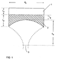
Figure 1 shows schematically a known system for generating focused ultrasound; -
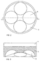
Figure 2 shows schematically in end elevation a system for generating high intensity focused ultrasound not falling within the scope of the present invention ; -
Figure 3 shows schematically and in cross-section the system ofFigure 2 ; -
Figures 4A and 4B shows schematically, in elevation and in cross section a composite system incorporating differential phase shift lens; -
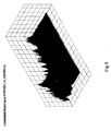
Figure 5 shows 3D plot of pressure amplitude up to 36mm from the lens surface over half the radiatory surface, i.e. 12.5mm from centre line; -
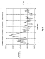
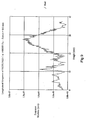
Figure 6 shows graphically pressure variation along the lens axis showing peak intensity 8mm from the lens surface; -
Figure 7 shows graphically radial variation of intensity of the focal plane; -
Figure 8 shows 3D plot of pressure amplitude up to 36mm from the lens surface over half the radiatory surface, i.e. 12.5mm from centre line; -
Figure 9 shows graphically pressure variation along the lens axis showing peak intensity 27mm from the lens surface; and -
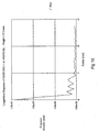
Figure 10 shows graphically radial variation of intensity of the focal plane. - Examples of apparatus embodying the invention are given below, by way of example and with reference to
Figure 1 of the drawings. - In the Examples,
- lp represents the thickness of the lens at its periphery;
- lc represents the thickness of the lens along its axis;
- do represents the diameter of the lens: and
- R represents the radius of curvature of the concave face of the lens.
- Referring now to
Figure 1 of the drawings, a piezoelectricceramic disc 1 is adapted to produce high frequency ultrasound in the 1 - 5 MHz range when excited at an appropriate frequency by electrical means (not shown). Immediately adjacent to the piezoelectricceramic disc 1, and affixed thereto by appropriate adhesive means, is a focusing plano-concave lens 2 of aluminium alloy, titanium alloy or other suitable material or mixture, whereby the ultrasonic vibration is directed to afocal zone 3 within the body wherein is located tissue to be treated. - An apparatus useful at a frequency in the region of 1.57MHz had lens dimensions as follows:
lp = 4.0mm lc = 1.5mm do = 10mm - An apparatus useful at a frequency in the region of 1.55MHz had lens dimensions as follows:
lp = 3.5mm lc = 1.5mm do = 10mm R = 7.5mm - An apparatus useful at a frequency in the region of 1.57MHz had lens dimensions as follows:
lp = 4.0mm lc = 1.5mm do = 10mm R = 6.26mm - Referring now to
Figures 2 and 3 , a single piezoelectric ceramic transducer, preferably of diameter 35mm, is attached to acomplex lens 5, of thickness preferably 12-13mm at its periphery and in the region of 8mm at its thinnest point. - The outer surface of the
lens 5 is formed to have four equiangularly spacedconcavities 6. Each forms part of a sphere, with the radii of curvature meeting at a preselected point. - More or less than four
concavities 6 may be provided. - Further Examples of theoretical determination of lens characteristics are given below:
- Results for a physical system of conjoined lens and PZT where:
- Thickness of PZT disc - l1 = 2mm
- Thickness of lens at periphery - l2= 7.5 mm
- Thickness of lens at axis - l3= 1.5 mm
- Radius of curvature of lens face - R= 15.25 mm
- Diameter of assembly - D = 25 mm
-
Figure 8 shows 3D plot of pressure amplitude upto 36mm from the lens surface over half the radiatory surface, i.e. 12.5mm from centre line; -
Figure 9 shows pressure variation along the lens axis showing peak intensity 27mm from the lens surface; and -
Figure 10 shows radial variation of intensity of the focal plane. - Results for a physical system of conjoined lens and PZT where:
- Thickness of PZT disc - l1 = 2mm
- Thickness of lens at periphery - l2= 4 mm
- Thickness of lens at axis - l3= 1.5 mm
- Radius of curvature of lens face - R= 6.25 mm
- Diameter of assembly - D = 10 mm
-
Figure 5 shows 3D plot of pressure amplitude upto 36mm from the lens surface over half the radiatory surface, i.e. 12.5mm from centre line; -
Figure 6 shows pressure variation along the lens axis showing peak intensity 27mm from the lens surface; and -
Figure 7 shows radial variation of intensity of the focal plane. - The beam cross section determined experimentally closely matches the theoretically predicted pattern.
- When a PZT transducer element is mechanically attached to a focussing device, a complex resonator is created which can only be analysed in its operating mode using sophisticated finite element techniques. Such methods have been refined to permit detailed analysis of the dynamic wave patters transmitted from close coupled duplex focussing transmitters which consist essentially of a plain disc PZT transducer, bonded to a plano-concave metal lens. The theory considers the geometry and acoustic properties of the duplex focussing device and simulates its operation when transmitting into fluid media over a wide range of frequencies. Such devices operate more like axial or radial resonators in longer wavelength systems and involve distortion of the lens which does not occur in optical systems. This technique allows specific focussing characteristics to be selected to satisfy the energy and geometrical requirements of a wide range of surgical procedures.
- Measurements were made in a beam plotting tank, in which a hydrophone is suspended within a volume of water into which an ultrasound device transmits. The hydrophone is accurately positioned relative to the transmitter, in three dimensions, using Vernier drives. The sensor measures the pressure developed by the travelling wave passing through the water, and converts this into a voltage signal; this is then plotted on a PC to produce a record of the transmission path shape. The width of the transmission path can be measured at known distances from the centre of the lens, allowing the calculation of the position of the minimum width, i.e. the "focal point"; and the degree of "focus", the ratio of lens surface area, and area of the transmission path at the "focal" plane.
- The material used for the lens was aluminium, for the ease of machining and good acoustic properties, and for the bond - standard Araldite (RTM) epoxy adhesive.
- The empirical investigation of lens geometry was carried out in two phases, based on the diameter of the PZT's employed. The previously developed ultrasonic radiating devices utilise 10mm diameter discs, thus the initial range of lenses were based on Ø10mm aluminium discs with one face given a concave machined radius of curvature. The initial radii chosen were intended to cover a representative range, and are listed in the table below.
Table 1 (all dimensions in mm) Radius Minimum Thickness (TL Min) Maximum Thickness (TL Max) 6.25 1.5 4.0 20.0 2.5 3.14 ∞ (Flat) 3.0 3.0 7.0 1.5 3.601 7.5 1.5 3.410 8.0 1.5 3.255 - The smallest radius of curvature was derived by taking the half-wavelength at 1 MHz in aluminium (which is ∼2.5mm) and making this the depth of the concave surface. This meant that if the minimum thickness was also 2.5mm, then theoretically the greatest amplitude at the lens surface would be shown both at the centre and extremity of the surface. The radius of 6.25mm was simply the result of fixing these dimensions.
- Various values of minimum thickness were examined for the first three radii of curvature, but only those listed in Table 1 showed noteworthy results, see Table 2. In light of these results the second three lens types were examined in order to investigate the apparent progress shown by the R6.25 (i.e. 6.25mm radius of curvature) types.
Table 2 (all dimensions in mm) Radius f/MHz Acoustic Output/mg1 Focal Length Transmission Path Ø Focussing Factor2 6.25 1.55 0 to 3 7.7 1.9 35.91 20.00 1.561 3 12 3.3 9.33 20.00 1.605 6 13 2.8 12.96 ∞ (Flat) 1.242 4 6 6.2 2.6 7.00 1.57 0 to 3 8 1.9 32.54 7.50 1.55 0 10 1.8 35.43 8.00 1.562 - 7 5.6 3.58 1 Force Balance measurement
2 Ratio of area of Transmission Path at Focal Plane to surface area of Lens - The first point to note is the small values obtained for Acoustic Output. This is due to two factors. Firstly, the crystals are "tuned" to a natural frequency of 1MHz, thus the modes of resonance giving required characteristics are "off-resonance", insofar as they are not at the natural resonant frequency of the systems. This results in poor energy transfer from the generator. Consequently, the generator should be optimised for the loads specific electrical characteristics, allowing modes of resonance not at the natural resonant frequency to be efficiently driven.
- The only example of the first group of lenses showing pronounced reduction in Transmission Path Diameter was the R6.25 lens with a minimum thickness of 1.5mm; those examples not listed failed to show a significant degree of "focus". Whilst the marginal levels of "focus" shown by the R20 (i.e. 20mm radius of curvature) and Flat examples are not in themselves impressive, they suggested a decrease in the desired characteristics with increasing radius of curvature. Most interestingly of all, the Flat lens still appears to illustrate a modicum of "focus".
- These results suggest a diffraction mechanism for the reduction in Transmission Path Diameter. The "focus" shown by the Flat lens may be attributed to a near field effect where destructive and constructive interference between waves transmitted from the surface produce a resultant converged path. The mechanism by which the greater decreases in Transmission Path Diameter are attained are also likely to be based on an interference form, in which case the decrease in radius was responsible for an amplification of this effect.
- In order to assess this premise, a second series, this time of Ø10 (10mm diameter) lenses, was produced. These investigated the effects of smaller increases in radius from the "optimum" R6.25 form. The results appear to show that a similar level of "focus" can be attained, but that it has a limit, reached with a radius of around 8.0mm, at which no resonant frequency showed a similarly pronounced "focus".
- The following conclusions may be drawn:
- The minimum thickness of the lens is preferably approximately 1.5mm.
- The radius of curvature of the lens and diameter of the disc should result in a pronounced depth to the lens.
- A generator should be capable of optimal matching to modes other than to the natural frequency of the transducer, since modes of resonance providing the required characteristics are not necessarily coincident with the natural resonant frequency.
- These conclusions led to a second phase of the empirical investigation. 025 (25mm diameter) PZT's were affixed to a range of aluminium lenses machined with radii of curvature shown below.
Table 3 (all dimensions in mm) Radius Minimum Thickness (TL Min) Maximum Thickness (TL Max) 15.625 1.5 7.753 17.5 1.5 6.753 20.0 1.5 5.888 - These transducers were investigated in the prescribed manner, the results being listed in Table 4.
Table 4 (all dimensions in mm) Radius f/MHz Acoustic Output/mg1 Focal Length Transmission Path Ø Focussing Factor2 15.625 1.232 155 19 2.1 177.38 15.625 1.242 285 23 1.8 241.18 15.625 1.334 120 12.5 3.8 54.12 17.50 1.405 130 20 2.1 166.92 20 1.255 180 24 4.2 39.81 20 1.436 35 24 2.0 175.59 20 1.492 10 22 2.1 159.35 1 Force Balance measurement
2 Ratio of area of Transmission Path at Focal Plane to surface area of Lens - The results listed in Table 4 show a dramatic increase in "focus" over those values measured for the Ø10 series of transducers. The increased acoustic output of the systems, compared to earlier, is also noticeable.
- The levels of "focus" measured are of the order needed to reach the intensities required to achieve denaturing in mammalian tissue. This achievement was the initial requirement to move on to identify the levels of Heat Generator in samples of "model" absorbing material.
- The experimental technique and principal of the set-up is quite simple. The transmitter being assessed is inserted into a lower holding tube, to a known depth. Water is injected into the space between the lens and the membrane covering the tube, all air being removed via a second tube/syringe. The upper portion of the system is mounted against the lower. The sample holder, containing the chosen absorbing material held in by a second membrane, is screwed down to the required height. Acoustic coupling gel acts as a lubricant between the two membranes and limits losses. The thermocouple holder is inserted into the top of the sample holder to measure initial temperature, it is then removed, the transducer activated for a fixed time, and the thermocouple re-introduced to measure the temperature rise due to the insonation. (Ambient temperature is simultaneously monitored as a control).
- The results, for absorption of energy transmitted from the 025, R15.625, TL Min 1.5 transducer, obtained in triethylene glycol (TEG), liver and a mixture of the two, are presented below.
Table 5 Absorbing Material Distance/mm1 Temperature Increase/°C TEG 23 19 Liver(water) 18 12 Liver(TEG) 18 14 1Distance from centre of lens to interface of membranes. - These results quoted are not the complete picture. The pattern of temperature rise, over a range of distances from the lens, does not smoothly rise to a maximum and then recede, it goes through a number of peaks and troughs. This is almost certainly due to the complicated nature of the transmission within the experimental cell.
- The nature of the material noted in
Entry 1 allows an energy balance to be carried out whereby a measure of the efficiency of the process can be measured:Acoustic Output from Transducer = 0.285/0.0688 = 4.142W Energy Transmitted during 5s insonation = 4.142 × 5 = 20.71J Average Energy Absorbed by TEG = 2.4 × 0.5625 × 15 = 20.25J Efficiency of Insonation Process = 20.25/20.71 = 97.8% - Thus, TEG is an excellent test material for assessment of Acoustic Absorption.
- In order to optimise the focussing effect of the close coupled generators, the propagation of wave energy from all parts of the concave output face should be directed substantially towards the generator axis, and each surface element of the concave radiating face should experience a displacement which is substantially in-phase with all neighbouring elements, in both circumferential and radial directions.
- These criteria can be met by consideration of the fact that different materials have individual acoustic properties, and the requisite level of control can be achieved by appropriate selection of materials.
- Referring now to
Figure 4A , there is shown a device in which the plano-concave lens comprises a plurality of annular sections (B,C, D, E) surrounding a central circular section (A). Each section is of a material having complimenting properties so that the wave from the planar face, contacting the PZT disc, will be transmitted from theconcave radiating face 8 in an optimum manner. - The device shown in
Figures 4A and 4B has concentric sections A, B, C, D and E, consisting of different materials each displaying an appropriate phase velocity constant, and separated bytubes 7 of an isolating material, for example PTFE. The elements of the concave, radiatingsurface 8 are adapted to meet the above criteria, i.e. with in-phase convergent waves transmitting fromsurface 8. Table 6, below shows by way of example materials and thei arrangement to give increasing phase velocity from the inner to the outer elements to compensate for the increase in thickness across the lens.Table 6. Element Material Acoustic Velocity/cms-1 A Aluminium Bronze 4.07 B K-Monel 4.3 C Ti Alloy 4.78 D Alumina 5.01 E Stainless Steel 5.16 - Optimum drive frequencies and annular widths consistent with a particular focussing radius can be determined.
- The advantages of this method of construction and design of the apparatus include:
- 1. Increased mechanical strength of the PZT lens structure.
- 2. Higher energy output per unit size.
- 3. Greater design flexibility.
- 4. Reduced unit cost.
- 5. Use of multi-head systems to create unique beam shapes.
Claims (6)
- An apparatus for focussing a beam of ultrasonic vibration comprising means to generate ultrasonic vibrations (1) and lens means (2) affixed to said generating means (1) and adapted to focus said ultrasonic vibration at a predetermined zone (3), whereby the lens means (2) is divided into a series of concentrically-arranged substantially annular regions (A, B, C, D, E), characterised in that each region comprises material having a wave velocity substantially different from that of adjacent regions (A, B, C, D, E).
- An apparatus as claimed in claim 1, characterised in that the wave velocities of said series of substantially annular regions (A, B, C, D, E) vary sequentially between an innermost region (A) and an outermost said region (E).
- An apparatus as claimed in either claim 1 or claim 2, characterised in that the wave velocities of said series of substantially annular regions (A, B, C, D, E) rise sequentially between an innermost region (A) and an outermost said region (E).
- An apparatus as claimed in any one of the preceding claims characterised in that the lens means (2) is plano-concave.
- An apparatus as claimed in any one of the preceding claims, characterised in that each said substantially annular region (A, B, C, D, E) is separated from adjacent regions (A, B, C, D, E) by an isolating material (7).
- An apparatus as claimed in any one of the preceding claims, characterised in that the lens means (2) comprises titanium, titanium alloy, aluminium, aluminium alloy, or a mixture containing any one or more of such materials.
Applications Claiming Priority (5)
| Application Number | Priority Date | Filing Date | Title |
|---|---|---|---|
| GB0201978 | 2002-01-29 | ||
| GB0201978A GB0201978D0 (en) | 2002-01-29 | 2002-01-29 | Method and apparatus for focussing ultrasonic energy |
| GB0212187 | 2002-05-28 | ||
| GB0212187A GB2384674B (en) | 2002-01-29 | 2002-05-28 | Method and apparatus for focussing ultrasonic energy |
| PCT/GB2003/000349 WO2003065347A1 (en) | 2002-01-29 | 2003-01-28 | Method and apparatus for focussing ultrasonic energy |
Publications (2)
| Publication Number | Publication Date |
|---|---|
| EP1470546A1 EP1470546A1 (en) | 2004-10-27 |
| EP1470546B1 true EP1470546B1 (en) | 2013-11-27 |
Family
ID=27665353
Family Applications (1)
| Application Number | Title | Priority Date | Filing Date |
|---|---|---|---|
| EP03702710.9A Expired - Lifetime EP1470546B1 (en) | 2002-01-29 | 2003-01-28 | Method and apparatus for focussing ultrasonic energy |
Country Status (4)
| Country | Link |
|---|---|
| US (1) | US7674233B2 (en) |
| EP (1) | EP1470546B1 (en) |
| JP (1) | JP4363987B2 (en) |
| WO (1) | WO2003065347A1 (en) |
Families Citing this family (65)
| Publication number | Priority date | Publication date | Assignee | Title |
|---|---|---|---|---|
| US6050943A (en) | 1997-10-14 | 2000-04-18 | Guided Therapy Systems, Inc. | Imaging, therapy, and temperature monitoring ultrasonic system |
| US7914453B2 (en) | 2000-12-28 | 2011-03-29 | Ardent Sound, Inc. | Visual imaging system for ultrasonic probe |
| US20050154332A1 (en) * | 2004-01-12 | 2005-07-14 | Onda | Methods and systems for removing hair using focused acoustic energy |
| WO2005079687A2 (en) | 2004-02-24 | 2005-09-01 | Applisonix Ltd. | Method and device for removing hair |
| US9011336B2 (en) | 2004-09-16 | 2015-04-21 | Guided Therapy Systems, Llc | Method and system for combined energy therapy profile |
| US7824348B2 (en) | 2004-09-16 | 2010-11-02 | Guided Therapy Systems, L.L.C. | System and method for variable depth ultrasound treatment |
| US7393325B2 (en) | 2004-09-16 | 2008-07-01 | Guided Therapy Systems, L.L.C. | Method and system for ultrasound treatment with a multi-directional transducer |
| US20130046209A1 (en) | 2011-07-10 | 2013-02-21 | Guided Therapy Systems, Llc | Systems and methods for improving an outside appearance of skin using ultrasound as an energy source |
| US8444562B2 (en) | 2004-10-06 | 2013-05-21 | Guided Therapy Systems, Llc | System and method for treating muscle, tendon, ligament and cartilage tissue |
| US10864385B2 (en) | 2004-09-24 | 2020-12-15 | Guided Therapy Systems, Llc | Rejuvenating skin by heating tissue for cosmetic treatment of the face and body |
| US8535228B2 (en) * | 2004-10-06 | 2013-09-17 | Guided Therapy Systems, Llc | Method and system for noninvasive face lifts and deep tissue tightening |
| WO2006042163A2 (en) | 2004-10-06 | 2006-04-20 | Guided Therapy Systems, L.L.C. | Method and system for cosmetic enhancement |
| US8690779B2 (en) | 2004-10-06 | 2014-04-08 | Guided Therapy Systems, Llc | Noninvasive aesthetic treatment for tightening tissue |
| US8133180B2 (en) | 2004-10-06 | 2012-03-13 | Guided Therapy Systems, L.L.C. | Method and system for treating cellulite |
| US9694212B2 (en) | 2004-10-06 | 2017-07-04 | Guided Therapy Systems, Llc | Method and system for ultrasound treatment of skin |
| KR20210068607A (en) | 2004-10-06 | 2021-06-09 | 가이디드 테라피 시스템스, 엘.엘.씨. | Ultrasound treatment system |
| US7758524B2 (en) | 2004-10-06 | 2010-07-20 | Guided Therapy Systems, L.L.C. | Method and system for ultra-high frequency ultrasound treatment |
| US11883688B2 (en) | 2004-10-06 | 2024-01-30 | Guided Therapy Systems, Llc | Energy based fat reduction |
| US11235179B2 (en) | 2004-10-06 | 2022-02-01 | Guided Therapy Systems, Llc | Energy based skin gland treatment |
| US9827449B2 (en) | 2004-10-06 | 2017-11-28 | Guided Therapy Systems, L.L.C. | Systems for treating skin laxity |
| US20060111744A1 (en) | 2004-10-13 | 2006-05-25 | Guided Therapy Systems, L.L.C. | Method and system for treatment of sweat glands |
| IL301311B2 (en) * | 2004-10-06 | 2026-01-01 | Guided Therapy Systems Llc | Therapeutic ultrasound treatment system |
| US20060079868A1 (en) * | 2004-10-07 | 2006-04-13 | Guided Therapy Systems, L.L.C. | Method and system for treatment of blood vessel disorders |
| US11207548B2 (en) | 2004-10-07 | 2021-12-28 | Guided Therapy Systems, L.L.C. | Ultrasound probe for treating skin laxity |
| US11724133B2 (en) | 2004-10-07 | 2023-08-15 | Guided Therapy Systems, Llc | Ultrasound probe for treatment of skin |
| EP1875327A2 (en) | 2005-04-25 | 2008-01-09 | Guided Therapy Systems, L.L.C. | Method and system for enhancing computer peripheral saftey |
| US8357095B2 (en) * | 2005-10-20 | 2013-01-22 | The General Hospital Corporation | Non-invasive treatment of fascia |
| US20070239079A1 (en) * | 2006-04-07 | 2007-10-11 | The General Hospital Corporation | Method and apparatus for selective treatment of biological tissue using ultrasound energy |
| US20080009774A1 (en) * | 2006-06-15 | 2008-01-10 | Capelli Christopher C | Methods of diminishing permanent tissue markings and related apparatus |
| US20080183110A1 (en) * | 2006-09-06 | 2008-07-31 | Davenport Scott A | Ultrasound system and method for hair removal |
| US20090171253A1 (en) * | 2006-09-06 | 2009-07-02 | Cutera, Inc. | System and method for dermatological treatment using ultrasound |
| US20080195000A1 (en) * | 2006-09-06 | 2008-08-14 | Spooner Gregory J R | System and Method for Dermatological Treatment Using Ultrasound |
| US9566454B2 (en) * | 2006-09-18 | 2017-02-14 | Guided Therapy Systems, Llc | Method and sysem for non-ablative acne treatment and prevention |
| US9241683B2 (en) | 2006-10-04 | 2016-01-26 | Ardent Sound Inc. | Ultrasound system and method for imaging and/or measuring displacement of moving tissue and fluid |
| WO2008137942A1 (en) | 2007-05-07 | 2008-11-13 | Guided Therapy Systems, Llc. | Methods and systems for modulating medicants using acoustic energy |
| US20150174388A1 (en) | 2007-05-07 | 2015-06-25 | Guided Therapy Systems, Llc | Methods and Systems for Ultrasound Assisted Delivery of a Medicant to Tissue |
| EP2152167B1 (en) | 2007-05-07 | 2018-09-05 | Guided Therapy Systems, L.L.C. | Methods and systems for coupling and focusing acoustic energy using a coupler member |
| US12102473B2 (en) | 2008-06-06 | 2024-10-01 | Ulthera, Inc. | Systems for ultrasound treatment |
| KR102087909B1 (en) | 2008-06-06 | 2020-03-12 | 얼테라, 인크 | A system for cosmetic treatment |
| US8585618B2 (en) * | 2008-12-22 | 2013-11-19 | Cutera, Inc. | Broad-area irradiation of small near-field targets using ultrasound |
| EP2382010A4 (en) | 2008-12-24 | 2014-05-14 | Guided Therapy Systems Llc | Methods and systems for fat reduction and/or cellulite treatment |
| US8715186B2 (en) | 2009-11-24 | 2014-05-06 | Guided Therapy Systems, Llc | Methods and systems for generating thermal bubbles for improved ultrasound imaging and therapy |
| EP2600937B8 (en) | 2010-08-02 | 2024-03-06 | Guided Therapy Systems, L.L.C. | Systems for treating acute and/or chronic injuries in soft tissue |
| US9504446B2 (en) | 2010-08-02 | 2016-11-29 | Guided Therapy Systems, Llc | Systems and methods for coupling an ultrasound source to tissue |
| US8857438B2 (en) | 2010-11-08 | 2014-10-14 | Ulthera, Inc. | Devices and methods for acoustic shielding |
| KR20190080967A (en) | 2011-07-11 | 2019-07-08 | 가이디드 테라피 시스템스, 엘.엘.씨. | Systems and methods for coupling an ultrasound source to tissue |
| US9263663B2 (en) | 2012-04-13 | 2016-02-16 | Ardent Sound, Inc. | Method of making thick film transducer arrays |
| US9510802B2 (en) | 2012-09-21 | 2016-12-06 | Guided Therapy Systems, Llc | Reflective ultrasound technology for dermatological treatments |
| CN204147427U (en) | 2012-11-26 | 2015-02-11 | 塞恩克公司 | Wearable electrocutaneous stimulation equipment |
| US9440070B2 (en) | 2012-11-26 | 2016-09-13 | Thyne Global, Inc. | Wearable transdermal electrical stimulation devices and methods of using them |
| CN113648551B (en) | 2013-03-08 | 2025-03-25 | 奥赛拉公司 | Device and method for multi-focus ultrasound therapy |
| US10561862B2 (en) | 2013-03-15 | 2020-02-18 | Guided Therapy Systems, Llc | Ultrasound treatment device and methods of use |
| US20160038770A1 (en) * | 2013-04-26 | 2016-02-11 | Thync, Inc. | Focused transcranial ultrasound systems and methods for using them |
| ES2696707T3 (en) | 2013-06-29 | 2019-01-17 | Cerevast Medical Inc | Transcutaneous electrical stimulation devices and methods to modify or induce the cognitive state |
| CN106573138A (en) | 2014-02-27 | 2017-04-19 | 赛威医疗公司 | Methods and apparatuses for user control of neurostimulation |
| CN106470735B (en) | 2014-04-18 | 2019-09-20 | 奥赛拉公司 | Ribbon transducer ultrasonic therapy |
| US9333334B2 (en) | 2014-05-25 | 2016-05-10 | Thync, Inc. | Methods for attaching and wearing a neurostimulator |
| KR102707101B1 (en) | 2016-01-18 | 2024-09-13 | 얼테라, 인크 | Compact ultrasound device having annular ultrasound array peripherally electrically connected to flexible printed circuit board and method of assembly thereof |
| IL301765B2 (en) | 2016-08-16 | 2025-01-01 | Ulthera Inc | Systems And Methods For Cosmetic Ultrasound Treatment Of Skin |
| TWI797235B (en) | 2018-01-26 | 2023-04-01 | 美商奧賽拉公司 | Systems and methods for simultaneous multi-focus ultrasound therapy in multiple dimensions |
| US11944849B2 (en) | 2018-02-20 | 2024-04-02 | Ulthera, Inc. | Systems and methods for combined cosmetic treatment of cellulite with ultrasound |
| IL321967A (en) | 2018-11-30 | 2025-09-01 | Ulthera Inc | Systems and methods for enhancing efficacy of ultrasound treatment |
| CA3137928A1 (en) | 2019-07-15 | 2021-01-21 | Ulthera, Inc. | Systems and methods for measuring elasticity with imaging of ultrasound multi-focus shearwaves in multiple dimensions |
| CN111112037A (en) * | 2020-01-20 | 2020-05-08 | 重庆医科大学 | Lens type multi-frequency focusing ultrasonic transducer, transduction system and method for determining axial length of acoustic focal region of lens type multi-frequency focusing ultrasonic transducer |
| KR102383268B1 (en) * | 2021-09-14 | 2022-04-08 | 주식회사 메타소닉 | Transducer of integrated type which generates complex ultrasonic sound |
Family Cites Families (7)
| Publication number | Priority date | Publication date | Assignee | Title |
|---|---|---|---|---|
| JPS4963401A (en) * | 1972-10-18 | 1974-06-19 | ||
| US4193473A (en) * | 1973-11-02 | 1980-03-18 | Thomson-Csf | Refractive stigmatic system for elastic surface waves |
| JPS5550438B2 (en) * | 1974-11-25 | 1980-12-18 | ||
| JP2763326B2 (en) * | 1989-03-31 | 1998-06-11 | オリンパス光学工業株式会社 | Ultrasound imaging lens system |
| US6755796B2 (en) * | 1999-02-07 | 2004-06-29 | Medispec Ltd. | Pressure-pulse therapy apparatus |
| US6200491B1 (en) * | 1999-03-23 | 2001-03-13 | Xerox Corporation | Fabrication process for acoustic lens array for use in ink printing |
| GB9915707D0 (en) * | 1999-07-05 | 1999-09-08 | Young Michael J R | Method and apparatus for focused treatment of subcutaneous blood vessels |
-
2003
- 2003-01-28 JP JP2003564855A patent/JP4363987B2/en not_active Expired - Fee Related
- 2003-01-28 WO PCT/GB2003/000349 patent/WO2003065347A1/en not_active Ceased
- 2003-01-28 EP EP03702710.9A patent/EP1470546B1/en not_active Expired - Lifetime
- 2003-01-28 US US10/502,919 patent/US7674233B2/en not_active Expired - Fee Related
Also Published As
| Publication number | Publication date |
|---|---|
| WO2003065347A1 (en) | 2003-08-07 |
| EP1470546A1 (en) | 2004-10-27 |
| US7674233B2 (en) | 2010-03-09 |
| JP2005516512A (en) | 2005-06-02 |
| US20050143677A1 (en) | 2005-06-30 |
| JP4363987B2 (en) | 2009-11-11 |
Similar Documents
| Publication | Publication Date | Title |
|---|---|---|
| US7674233B2 (en) | Method and apparatus for focussing ultrasonic energy | |
| US8162858B2 (en) | Ultrasonic medical treatment device with variable focal zone | |
| US11832843B2 (en) | Ultrasonic surgical instrument, associated surgical method and related manufacturing method | |
| US6971994B1 (en) | Method and apparatus for focussing ultrasonic energy | |
| US10070883B2 (en) | Systems and method for ultra-high frequency ultrasound treatment | |
| US20110178541A1 (en) | Virtual ultrasonic scissors | |
| US20120143100A1 (en) | Extended depth-of-focus high intensity ultrasonic transducer | |
| US20130051178A1 (en) | Resonantly amplified shear waves | |
| US20090093737A1 (en) | Ultrasound apparatus with treatment lens | |
| US20090171255A1 (en) | Apparatus and method for ultrasound treatment | |
| CN217794153U (en) | Therapeutic head with multiple ultrasonic energy conversion units and ultrasonic therapeutic apparatus | |
| US11305133B2 (en) | Efficient acoustic energy transfer through skull via excitation of Lamb waves | |
| Rybyanets | New methods and transducer designs for ultrasonic diagnostics and therapy | |
| US20110288457A1 (en) | Sonic resonator system for use in biomedical applications | |
| US20240416151A1 (en) | Integrally-structured complex ultrasound generation transducer | |
| US5228447A (en) | Shockwave generator having an ultrasound applicator shielded from shockwaves | |
| US20100249670A1 (en) | High-power multiple-harmonic ultrasound transducer | |
| GB2384674A (en) | Lens to focus ultrasonic vibration at a predetermined zone | |
| Yamada et al. | Tube-type double-parabolic-reflector ultrasonic transducer (T-DPLUS) | |
| JP2012005602A (en) | Ultrasonic irradiation device | |
| CN120323036B (en) | Ultrasonic vibrator and ultrasonic therapeutic device having the same | |
| Stevenson et al. | Optimising the Materials of a FUS Transducer Sized for Robotic Delivery | |
| Singh et al. | A multi-frequency multi-focal length ultrasonic therapy transducer | |
| CN116511014A (en) | Single/double-frequency array transducer for multiple regulation and control of sound field and focal domain volume | |
| Jarosz | Measurement of Acoustic Output of Ultrasound Instrumentation for Interstitial Thermal Therapy |
Legal Events
| Date | Code | Title | Description |
|---|---|---|---|
| PUAI | Public reference made under article 153(3) epc to a published international application that has entered the european phase |
Free format text: ORIGINAL CODE: 0009012 |
|
| 17P | Request for examination filed |
Effective date: 20040727 |
|
| AK | Designated contracting states |
Kind code of ref document: A1 Designated state(s): AT BE BG CH CY CZ DE DK EE ES FI FR GB GR HU IE IT LI LU MC NL PT SE SI SK TR |
|
| AX | Request for extension of the european patent |
Extension state: AL LT LV MK RO |
|
| 17Q | First examination report despatched |
Effective date: 20100323 |
|
| GRAP | Despatch of communication of intention to grant a patent |
Free format text: ORIGINAL CODE: EPIDOSNIGR1 |
|
| INTG | Intention to grant announced |
Effective date: 20130611 |
|
| GRAS | Grant fee paid |
Free format text: ORIGINAL CODE: EPIDOSNIGR3 |
|
| GRAA | (expected) grant |
Free format text: ORIGINAL CODE: 0009210 |
|
| RAP1 | Party data changed (applicant data changed or rights of an application transferred) |
Owner name: SRA DEVELOPMENTS LIMITED |
|
| RIN1 | Information on inventor provided before grant (corrected) |
Inventor name: YOUNG, MICHAEL JOHN RADLEY Inventor name: YOUNG, STEPHEN MICHAEL RADLEY |
|
| AK | Designated contracting states |
Kind code of ref document: B1 Designated state(s): AT BE BG CH CY CZ DE DK EE ES FI FR GB GR HU IE IT LI LU MC NL PT SE SI SK TR |
|
| REG | Reference to a national code |
Ref country code: GB Ref legal event code: FG4D |
|
| REG | Reference to a national code |
Ref country code: CH Ref legal event code: EP |
|
| REG | Reference to a national code |
Ref country code: AT Ref legal event code: REF Ref document number: 642993 Country of ref document: AT Kind code of ref document: T Effective date: 20131215 |
|
| REG | Reference to a national code |
Ref country code: IE Ref legal event code: FG4D |
|
| REG | Reference to a national code |
Ref country code: DE Ref legal event code: R096 Ref document number: 60345361 Country of ref document: DE Effective date: 20140123 |
|
| REG | Reference to a national code |
Ref country code: NL Ref legal event code: VDEP Effective date: 20131127 |
|
| REG | Reference to a national code |
Ref country code: AT Ref legal event code: MK05 Ref document number: 642993 Country of ref document: AT Kind code of ref document: T Effective date: 20131127 |
|
| PG25 | Lapsed in a contracting state [announced via postgrant information from national office to epo] |
Ref country code: NL Free format text: LAPSE BECAUSE OF FAILURE TO SUBMIT A TRANSLATION OF THE DESCRIPTION OR TO PAY THE FEE WITHIN THE PRESCRIBED TIME-LIMIT Effective date: 20131127 Ref country code: SE Free format text: LAPSE BECAUSE OF FAILURE TO SUBMIT A TRANSLATION OF THE DESCRIPTION OR TO PAY THE FEE WITHIN THE PRESCRIBED TIME-LIMIT Effective date: 20131127 Ref country code: FI Free format text: LAPSE BECAUSE OF FAILURE TO SUBMIT A TRANSLATION OF THE DESCRIPTION OR TO PAY THE FEE WITHIN THE PRESCRIBED TIME-LIMIT Effective date: 20131127 |
|
| PG25 | Lapsed in a contracting state [announced via postgrant information from national office to epo] |
Ref country code: CY Free format text: LAPSE BECAUSE OF FAILURE TO SUBMIT A TRANSLATION OF THE DESCRIPTION OR TO PAY THE FEE WITHIN THE PRESCRIBED TIME-LIMIT Effective date: 20131127 Ref country code: AT Free format text: LAPSE BECAUSE OF FAILURE TO SUBMIT A TRANSLATION OF THE DESCRIPTION OR TO PAY THE FEE WITHIN THE PRESCRIBED TIME-LIMIT Effective date: 20131127 Ref country code: ES Free format text: LAPSE BECAUSE OF FAILURE TO SUBMIT A TRANSLATION OF THE DESCRIPTION OR TO PAY THE FEE WITHIN THE PRESCRIBED TIME-LIMIT Effective date: 20131127 Ref country code: BE Free format text: LAPSE BECAUSE OF FAILURE TO SUBMIT A TRANSLATION OF THE DESCRIPTION OR TO PAY THE FEE WITHIN THE PRESCRIBED TIME-LIMIT Effective date: 20131127 |
|
| PG25 | Lapsed in a contracting state [announced via postgrant information from national office to epo] |
Ref country code: PT Free format text: LAPSE BECAUSE OF FAILURE TO SUBMIT A TRANSLATION OF THE DESCRIPTION OR TO PAY THE FEE WITHIN THE PRESCRIBED TIME-LIMIT Effective date: 20140327 |
|
| PG25 | Lapsed in a contracting state [announced via postgrant information from national office to epo] |
Ref country code: EE Free format text: LAPSE BECAUSE OF FAILURE TO SUBMIT A TRANSLATION OF THE DESCRIPTION OR TO PAY THE FEE WITHIN THE PRESCRIBED TIME-LIMIT Effective date: 20131127 |
|
| REG | Reference to a national code |
Ref country code: DE Ref legal event code: R097 Ref document number: 60345361 Country of ref document: DE |
|
| PG25 | Lapsed in a contracting state [announced via postgrant information from national office to epo] |
Ref country code: MC Free format text: LAPSE BECAUSE OF FAILURE TO SUBMIT A TRANSLATION OF THE DESCRIPTION OR TO PAY THE FEE WITHIN THE PRESCRIBED TIME-LIMIT Effective date: 20131127 Ref country code: CZ Free format text: LAPSE BECAUSE OF FAILURE TO SUBMIT A TRANSLATION OF THE DESCRIPTION OR TO PAY THE FEE WITHIN THE PRESCRIBED TIME-LIMIT Effective date: 20131127 Ref country code: LU Free format text: LAPSE BECAUSE OF FAILURE TO SUBMIT A TRANSLATION OF THE DESCRIPTION OR TO PAY THE FEE WITHIN THE PRESCRIBED TIME-LIMIT Effective date: 20140128 Ref country code: SK Free format text: LAPSE BECAUSE OF FAILURE TO SUBMIT A TRANSLATION OF THE DESCRIPTION OR TO PAY THE FEE WITHIN THE PRESCRIBED TIME-LIMIT Effective date: 20131127 |
|
| PG25 | Lapsed in a contracting state [announced via postgrant information from national office to epo] |
Ref country code: DK Free format text: LAPSE BECAUSE OF FAILURE TO SUBMIT A TRANSLATION OF THE DESCRIPTION OR TO PAY THE FEE WITHIN THE PRESCRIBED TIME-LIMIT Effective date: 20131127 |
|
| PLBE | No opposition filed within time limit |
Free format text: ORIGINAL CODE: 0009261 |
|
| STAA | Information on the status of an ep patent application or granted ep patent |
Free format text: STATUS: NO OPPOSITION FILED WITHIN TIME LIMIT |
|
| 26N | No opposition filed |
Effective date: 20140828 |
|
| REG | Reference to a national code |
Ref country code: IE Ref legal event code: MM4A |
|
| REG | Reference to a national code |
Ref country code: DE Ref legal event code: R097 Ref document number: 60345361 Country of ref document: DE Effective date: 20140828 |
|
| PG25 | Lapsed in a contracting state [announced via postgrant information from national office to epo] |
Ref country code: IE Free format text: LAPSE BECAUSE OF NON-PAYMENT OF DUE FEES Effective date: 20140128 |
|
| PG25 | Lapsed in a contracting state [announced via postgrant information from national office to epo] |
Ref country code: SI Free format text: LAPSE BECAUSE OF FAILURE TO SUBMIT A TRANSLATION OF THE DESCRIPTION OR TO PAY THE FEE WITHIN THE PRESCRIBED TIME-LIMIT Effective date: 20131127 |
|
| PGFP | Annual fee paid to national office [announced via postgrant information from national office to epo] |
Ref country code: IT Payment date: 20150113 Year of fee payment: 13 |
|
| REG | Reference to a national code |
Ref country code: FR Ref legal event code: PLFP Year of fee payment: 14 |
|
| PG25 | Lapsed in a contracting state [announced via postgrant information from national office to epo] |
Ref country code: BG Free format text: LAPSE BECAUSE OF FAILURE TO SUBMIT A TRANSLATION OF THE DESCRIPTION OR TO PAY THE FEE WITHIN THE PRESCRIBED TIME-LIMIT Effective date: 20131127 |
|
| PG25 | Lapsed in a contracting state [announced via postgrant information from national office to epo] |
Ref country code: GR Free format text: LAPSE BECAUSE OF FAILURE TO SUBMIT A TRANSLATION OF THE DESCRIPTION OR TO PAY THE FEE WITHIN THE PRESCRIBED TIME-LIMIT Effective date: 20140228 |
|
| PG25 | Lapsed in a contracting state [announced via postgrant information from national office to epo] |
Ref country code: HU Free format text: LAPSE BECAUSE OF FAILURE TO SUBMIT A TRANSLATION OF THE DESCRIPTION OR TO PAY THE FEE WITHIN THE PRESCRIBED TIME-LIMIT; INVALID AB INITIO Effective date: 20030128 Ref country code: TR Free format text: LAPSE BECAUSE OF FAILURE TO SUBMIT A TRANSLATION OF THE DESCRIPTION OR TO PAY THE FEE WITHIN THE PRESCRIBED TIME-LIMIT Effective date: 20131127 |
|
| PG25 | Lapsed in a contracting state [announced via postgrant information from national office to epo] |
Ref country code: IT Free format text: LAPSE BECAUSE OF NON-PAYMENT OF DUE FEES Effective date: 20160128 |
|
| REG | Reference to a national code |
Ref country code: FR Ref legal event code: PLFP Year of fee payment: 15 |
|
| PGFP | Annual fee paid to national office [announced via postgrant information from national office to epo] |
Ref country code: FR Payment date: 20170331 Year of fee payment: 15 Ref country code: CH Payment date: 20170331 Year of fee payment: 15 |
|
| PGFP | Annual fee paid to national office [announced via postgrant information from national office to epo] |
Ref country code: DE Payment date: 20170331 Year of fee payment: 15 |
|
| REG | Reference to a national code |
Ref country code: DE Ref legal event code: R119 Ref document number: 60345361 Country of ref document: DE |
|
| REG | Reference to a national code |
Ref country code: CH Ref legal event code: PL |
|
| PG25 | Lapsed in a contracting state [announced via postgrant information from national office to epo] |
Ref country code: FR Free format text: LAPSE BECAUSE OF NON-PAYMENT OF DUE FEES Effective date: 20180131 Ref country code: DE Free format text: LAPSE BECAUSE OF NON-PAYMENT OF DUE FEES Effective date: 20180801 |
|
| REG | Reference to a national code |
Ref country code: FR Ref legal event code: ST Effective date: 20180928 |
|
| PG25 | Lapsed in a contracting state [announced via postgrant information from national office to epo] |
Ref country code: LI Free format text: LAPSE BECAUSE OF NON-PAYMENT OF DUE FEES Effective date: 20180131 Ref country code: CH Free format text: LAPSE BECAUSE OF NON-PAYMENT OF DUE FEES Effective date: 20180131 |
|
| PGFP | Annual fee paid to national office [announced via postgrant information from national office to epo] |
Ref country code: GB Payment date: 20190118 Year of fee payment: 17 |
|
| GBPC | Gb: european patent ceased through non-payment of renewal fee |
Effective date: 20200128 |
|
| PG25 | Lapsed in a contracting state [announced via postgrant information from national office to epo] |
Ref country code: GB Free format text: LAPSE BECAUSE OF NON-PAYMENT OF DUE FEES Effective date: 20200128 |