EP1470335B1 - Reciprocating fluid engine - Google Patents
Reciprocating fluid engine Download PDFInfo
- Publication number
- EP1470335B1 EP1470335B1 EP02798634A EP02798634A EP1470335B1 EP 1470335 B1 EP1470335 B1 EP 1470335B1 EP 02798634 A EP02798634 A EP 02798634A EP 02798634 A EP02798634 A EP 02798634A EP 1470335 B1 EP1470335 B1 EP 1470335B1
- Authority
- EP
- European Patent Office
- Prior art keywords
- chamber
- fluid
- passage
- valve stem
- piston
- Prior art date
- Legal status (The legal status is an assumption and is not a legal conclusion. Google has not performed a legal analysis and makes no representation as to the accuracy of the status listed.)
- Expired - Lifetime
Links
- 239000012530 fluid Substances 0.000 title claims abstract description 99
- 238000000034 method Methods 0.000 claims description 4
- 230000000903 blocking effect Effects 0.000 claims description 2
- 230000004044 response Effects 0.000 claims description 2
- 238000013022 venting Methods 0.000 claims 2
- 241000238631 Hexapoda Species 0.000 description 1
- 230000007423 decrease Effects 0.000 description 1
- 238000010304 firing Methods 0.000 description 1
- 230000007246 mechanism Effects 0.000 description 1
- 230000004048 modification Effects 0.000 description 1
- 238000012986 modification Methods 0.000 description 1
- 210000003205 muscle Anatomy 0.000 description 1
- 230000009467 reduction Effects 0.000 description 1
- 230000000717 retained effect Effects 0.000 description 1
- 238000007789 sealing Methods 0.000 description 1
- 239000000126 substance Substances 0.000 description 1
Images




Classifications
-
- F—MECHANICAL ENGINEERING; LIGHTING; HEATING; WEAPONS; BLASTING
- F01—MACHINES OR ENGINES IN GENERAL; ENGINE PLANTS IN GENERAL; STEAM ENGINES
- F01B—MACHINES OR ENGINES, IN GENERAL OR OF POSITIVE-DISPLACEMENT TYPE, e.g. STEAM ENGINES
- F01B11/00—Reciprocating-piston machines or engines without rotary main shaft, e.g. of free-piston type
- F01B11/001—Reciprocating-piston machines or engines without rotary main shaft, e.g. of free-piston type in which the movement in the two directions is obtained by one double acting piston motor
-
- B—PERFORMING OPERATIONS; TRANSPORTING
- B64—AIRCRAFT; AVIATION; COSMONAUTICS
- B64D—EQUIPMENT FOR FITTING IN OR TO AIRCRAFT; FLIGHT SUITS; PARACHUTES; ARRANGEMENT OR MOUNTING OF POWER PLANTS OR PROPULSION TRANSMISSIONS IN AIRCRAFT
- B64D27/00—Arrangement or mounting of power plants in aircraft; Aircraft characterised by the type or position of power plants
- B64D27/02—Aircraft characterised by the type or position of power plants
- B64D27/04—Aircraft characterised by the type or position of power plants of piston type
-
- B—PERFORMING OPERATIONS; TRANSPORTING
- B64—AIRCRAFT; AVIATION; COSMONAUTICS
- B64U—UNMANNED AERIAL VEHICLES [UAV]; EQUIPMENT THEREFOR
- B64U10/00—Type of UAV
- B64U10/40—Ornithopters
-
- F—MECHANICAL ENGINEERING; LIGHTING; HEATING; WEAPONS; BLASTING
- F01—MACHINES OR ENGINES IN GENERAL; ENGINE PLANTS IN GENERAL; STEAM ENGINES
- F01B—MACHINES OR ENGINES, IN GENERAL OR OF POSITIVE-DISPLACEMENT TYPE, e.g. STEAM ENGINES
- F01B17/00—Reciprocating-piston machines or engines characterised by use of uniflow principle
- F01B17/02—Engines
-
- F—MECHANICAL ENGINEERING; LIGHTING; HEATING; WEAPONS; BLASTING
- F01—MACHINES OR ENGINES IN GENERAL; ENGINE PLANTS IN GENERAL; STEAM ENGINES
- F01L—CYCLICALLY OPERATING VALVES FOR MACHINES OR ENGINES
- F01L21/00—Use of working pistons or pistons-rods as fluid-distributing valves or as valve-supporting elements, e.g. in free-piston machines
- F01L21/04—Valves arranged in or on piston or piston-rod
-
- F—MECHANICAL ENGINEERING; LIGHTING; HEATING; WEAPONS; BLASTING
- F01—MACHINES OR ENGINES IN GENERAL; ENGINE PLANTS IN GENERAL; STEAM ENGINES
- F01L—CYCLICALLY OPERATING VALVES FOR MACHINES OR ENGINES
- F01L23/00—Valves controlled by impact by piston, e.g. in free-piston machines
-
- F—MECHANICAL ENGINEERING; LIGHTING; HEATING; WEAPONS; BLASTING
- F02—COMBUSTION ENGINES; HOT-GAS OR COMBUSTION-PRODUCT ENGINE PLANTS
- F02B—INTERNAL-COMBUSTION PISTON ENGINES; COMBUSTION ENGINES IN GENERAL
- F02B75/00—Other engines
- F02B75/34—Ultra-small engines, e.g. for driving models
-
- F—MECHANICAL ENGINEERING; LIGHTING; HEATING; WEAPONS; BLASTING
- F15—FLUID-PRESSURE ACTUATORS; HYDRAULICS OR PNEUMATICS IN GENERAL
- F15B—SYSTEMS ACTING BY MEANS OF FLUIDS IN GENERAL; FLUID-PRESSURE ACTUATORS, e.g. SERVOMOTORS; DETAILS OF FLUID-PRESSURE SYSTEMS, NOT OTHERWISE PROVIDED FOR
- F15B21/00—Common features of fluid actuator systems; Fluid-pressure actuator systems or details thereof, not covered by any other group of this subclass
- F15B21/12—Fluid oscillators or pulse generators
-
- F—MECHANICAL ENGINEERING; LIGHTING; HEATING; WEAPONS; BLASTING
- F01—MACHINES OR ENGINES IN GENERAL; ENGINE PLANTS IN GENERAL; STEAM ENGINES
- F01L—CYCLICALLY OPERATING VALVES FOR MACHINES OR ENGINES
- F01L3/00—Lift-valve, i.e. cut-off apparatus with closure members having at least a component of their opening and closing motion perpendicular to the closing faces; Parts or accessories thereof
- F01L2003/25—Valve configurations in relation to engine
Definitions
- the present invention relates to a reciprocating fluid engine. More particularly, the present invention relates to a reciprocating fluid engine in which every stroke of the piston is a drive stroke. Still more particularly, the present invention relates to a toy ornithopter having a reciprocating fluid engine in which every stroke of the piston is a drive stroke.
- German Patent Application No. DE19782823667 to Roser describes a compressed air motor having a cylinder with a piston slidable in the cylinder and connected to a compressed air inlet through a slide valve mechanism which alternately admits respective opposite sides of the cylinder with compressed air for driving the piston in the opposite direction and which alternately vents the side of the cylinder in which the piston is moving.
- German Patent Application No. 19591230264 to Zoller , geb. Kehl et al., describes the use of seals.
- Another object of the present invention is to provide a toy vehicle powered by an engine that has a reduced number of parts.
- Another object of the present invention is to provide a toy ornithopter in which the piston provides a direct drive to the flapping wings, thereby eliminating the need for gear reduction from a rotary motor.
- a toy ornithopter comprising:
- FIG. 1 is a cross section of an engine according to the present invention in which the valve stem and piston are in a lowermost position;
- FIG. 2 is a cross section of the engine according to the present invention in which the valve stem is in a lowermost position and the piston is moving upward;
- FIG. 3 is a cross section of the engine according to the present invention in which the valve stem and piston are in an uppermost position
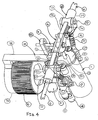
- FIG. 4 is a perspective view of the engine of FIG. 1 ;
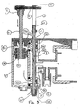
- FIG. 5 is a top view of the engine of FIG. 4 ;
- FIG. 6 is an exploded perspective view of an ornithopter having the engine of FIG. 1 ;
- FIG. 7 is an exploded perspective view of the ornithopter of FIG. 6 showing the engine fully assembled
- FIG. 8 is an elevational view of the ornithopter of FIG. 7 fully assembled
- FIG. 9 is a top plan view of the ornithopter of FIG. 8 having main and rear wings;
- FIG. 10 is a perspective view of the ornithopter of FIG. 9 .
- a reciprocating fluid engine 31 according to the present invention is shown in FIGS. 1 - 6 .
- the reciprocating fluid engine 31 produces a high frequency and a high stroke force. Preferably, the frequency is approximately twenty (20) hertz.
- the reciprocating fluid engine 31 may be used to power a vehicle, such as a toy ornithopter 51, as shown in FIGS. 6 - 10 .
- the reciprocating fluid engine 31 drives a piston assembly 50 in which every stroke of the piston assembly is a drive stroke, such that each stroke of the piston assembly powers the vehicle in some manner.
- each stroke of the piston assembly 50 moves the wings 81 of the ornithopter either up or down, thereby causing the wings to flap with every stroke of the piston assembly.
- the following description relates to the reciprocating fluid engine 31 of the present invention being used to power a toy ornithopter 51, although the use of the reciprocating fluid engine is not limited to powering toy ornithopters.
- Fluid is pumped into a high pressure, lightweight container or storage vessel 15 using a standard piston fluid pump 61, as shown in FIGS. 1 - 6 .
- the fluid is high pressure air.
- the high pressure storage vessel 15 is mechanically attached to the reciprocating fluid engine 31 through an intake manifold 13.
- storage vessel 15 is threadably connected to intake manifold 13.
- Fluid pump 61 connects to the intake manifold 13 through an adapter 14.
- the intake manifold 13 has a fluid input receptacle 19 with a one way check valve 17 and spring 18. Fluid entering receptacle 19 forces the check valve 17 to compress spring 18, thereby allowing the fluid to enter the manifold 13.
- the spring 18 When no fluid is entering receptacle 19, the spring 18 maintains the check valve in a seated position with the adapter 14, thereby preventing fluid from escaping from the manifold 13 through the receptacle and adapter.
- the fluid is also retained within the vessel 15 and a first chamber 12 of the engine 31 by the timing valve stem 1 and by first and second inner seals 2C and 2B, respectively.
- a valve stem 1 is substantially disposed in the first chamber or valve stem cylinder 12, which is preferably cylindrical.
- the first chamber 12 has a first opening 63 and a second opening 65 at opposing ends of the chamber.
- the valve stem 1 has a first end 67 and a second end 69.
- the first end 67 of the valve stem 1 extends through a first opening 63 in the first chamber 12.
- the second end 69 of the valve stem 1 extends through a second opening 65 of the first chamber 12 and through a first opening 72 in housing bracket 16.
- the first end 67 of the valve stem is connected to a stem stop 68.
- the second end 69 of the valve stem 1 is received by the valve timing member 55.
- Valve stem 1 has four undercuts or grooves 41, 42, 43 and 44.
- Four seals 2A, 2B, 2C and 2D are mounted on an inner wall 40 of the valve stem cylinder 12.
- the seals are O-rings or cup seals.
- the valve stem 1 moves reciprocatingly within the valve stem cylinder 12 and through an opening in each of the seals 2A, 2B, 2C and 2D, as shown in FIGS. 1 - 3 .
- Each undercut 41, 42, 43 and 44 in the valve stem 1 is adapted to receive one of the seals 2A, 2B, 2C and 2D.
- First undercut 44 receives first outer seal 2D.
- Second undercut 43 receives first inner seal 2C.
- Third undercut 42 receives second inner seal 2B.
- Fourth undercut 41 receives second outer seal 2A.
- a seal When a seal is aligned with its corresponding undercut, fluid is allowed to pass between that seal and the valve stem.
- a seal When a seal is not aligned with its corresponding undercut, a tight seal is formed within the valve stem cylinder 12 by that seal, the inner valve stem cylinder wall 40 and valve stem 1, thereby preventing fluid from passing.
- This seal prevents passage of fluid from the vessel 15 either to a second chamber or piston cylinder 11 or to vent to the atmosphere through first and second openings 63 and 65 in the valve stem cylinder 12.
- the second chamber or piston cylinder 11 is fluidly connected to the first chamber (valve stem cylinder 12) by first and second passages 11B and 11A, respectively.
- the piston assembly 50 is substantially disposed within the second chamber 11.
- the piston assembly 50 includes a connecting rod 6, a piston 7 connected to a first end 25 of the connecting rod, upper and lower piston seals 8A and 8B attached to upper and lower surfaces of the piston, and a bracket 5 connected to a second end 26 of the rod.
- the second chamber 11 has an open end 78, as shown in FIG. 6 .
- the open end 78 of the second chamber 11 is sealed with a connecting rod seal 10 th ⁇ t is secured to the second chamber by a second chamber portion 77 of housing bracket 16, as shown in FIGS. 1 - 3 .
- An opening 24 in the connecting rod seal 10 and an opening 73 in the housing bracket 16 allow for reciprocal movement therethrough of the connecting rod 6.
- Housing bracket 16 secures the vessel 15, first chamber 12 and second chamber 11 together.
- the housing bracket 16 has a cylindrical portion 74 for receiving the vessel 15.
- a bracket arm 75 extends perpendicularly from the cylindrical portion 74 of the housing bracket 16.
- the bracket arm 75 has a first chamber portion 76 for capping the second opening 65 of the first chamber 12.
- a first opening 72 in the first chamber portion 76 of the bracket arm 75 receives second end 69 of the valve stem 1.
- the bracket arm 75 has a second chamber portion 77 for receiving connecting rod seal 10, thereby sealing opening 78 in second chamber 11.
- the second chamber portion 77 of the bracket arm 75 has a second opening 73 for receiving connecting rod 6.
- Seal 9A positioned between first and second chambers 12 and 11 proximal second passage 11A prevents fluid leakage between the chambers.
- Seal 9B positioned between first and second chambers 12 and 11 proximal first passage 11B prevents fluid leakage between first and second chambers.
- Bracket 5 is attached to a second end 26 of the connecting rod 6.
- a first end 27 of horizontal guide rod 4 is secured to bracket 5.
- a second end 28 of the horizontal guide rod 4 passes through an opening 3 (stem timing slot) in a stem timing member 55.
- the stem timing member 55 is connected to the second end 69 of the valve stem 1.
- Leading edge adapters 20 are connected to opposite ends of the bracket 5, as shown in FIGS. 4 - 6 and 9 - 10 .
- the leading edge adapters 20 have a central portion 53, a linking arm 32 extending from the central portion and an outer strut receiver 54 extending from the central portion.
- the central portion 53 is substantially cylindrical with first and second openings 56 and 58.
- the first opening 56 receives a pin 23 to pivotally connect the leading edge adapter 20 to a strut support 33.
- a second opening 58 receives a rearwardly extending strut 91.
- a leading edge inner strut 21 extends outwardly from each of the outer strut receivers of the leading edge adapters 20.
- Leading edge adapters 20 pivot about pins 23, which secure the adapters to the strut connectors 33.
- the strut connectors 33 are pinned to the leading edge adapters 20 at a first end, and the second end of the strut connectors is secured to the piston cylinder 11.
- Linking arms 32 on the leading edge adapters 20 connect the leading edge adapters to the bracket 5.
- slots 34 in the leading edge adapters 20 receive pins 36 of bracket 5, to allow movement of the adapter with respect to the bracket, thereby providing a degree of flexibility to the wings 81.
- Wings 81 are supported by a plurality of strut members.
- outer struts 22 extend from the leading edge inner struts 21.
- Straight connecting members 46 are used to connect the inner and outer struts 21 and 22.
- "Y" connecting members 47 and 49 positioned on the inner and rear struts 21 and 91, respectively, are used to connect cross-support struts 48.
- Wings 81 are attached to the inner, outer, rear and cross-support struts 21, 22, 91 and 48 in any suitable manner.
- Engine 31 is substantially disposed in engine housing 83, as shown in FIGS. 7 and 8 .
- the engine housing 83 includes first and second engine housing portions 84 and 85 for substantially enclosing the engine 31 within the engine housing 83.
- the cylindrical portion 74 of the bracket housing 16 is secured to a front end 88 of the body housing 87.
- Rear wing 71 is connected to a rear end 89 of the body housing 87.
- the vessel 15 is initially pressurized by connecting fluid pump 61 to adapter 14 and pressurizing the vessel as desired. Once the vessel 15 is pressurized, the ornithopter 51 is in operational condition. When the toy ornithopter 51 is launched, i.e., thrown into the air, air pressure forces the wings 81 upward, thereby also moving the inner and outer struts 21 and 22 upward since they are connected to the wings. Upward movement of the inner and outer struts 21 and 22 causes upward movement of the outer strut receivers 54 of the leading edge adapters. As the outer strut receivers move upward, the leading edge adapters 20 rotate about pins 23, thereby causing the linking arms 32 to move downward.
- Valve stem 1 has three basic positions during a normal cycle of the engine: a center position, a lowermost position ( FIGS. 1 and 2 ), and an uppermost position ( FIG. 3 ).
- the center position corresponds to the position of the valve stem 1 prior to launching the ornithopter 51, such that the fluid is stored in the vessel 15 and the first chamber 12 between the first and second inner seals 2C and 2B.
- the lowermost position of the valve stem shown in FIG. 1 corresponds to the position of the valve stem described in the paragraph above just after launching the ornithopter, i.e., when the bracket 5 and valve stem 1 are in their lowermost positions proximal the housing bracket 16.
- the first position of the valve stem 1 is the center or middle position. In the center position, the fluid held in the pressure vessel is shut off between the valve stem 1 and first and second inner seals 2C and 2B, thereby preventing fluid from passing from the first chamber to the second chamber. This prevents the engine 31 from running.
- valve stem 1 When the valve stem 1 is in the lowermost position, as shown in FIGS. 1 and 2 , the fluid is stopped between the valve stem 1 and second inner seal 2B. The fluid passes by valve stem 1 and first inner seal 2C since the first inner seal is seated in undercut 43. The fluid then passes through a first passage or orifice 11B and into the second chamber or piston cylinder 11. The fluid is prevented from escaping to the atmosphere through first opening 63 in the first chamber 12 by the tight seal formed between first outer seal 2D, inner surface 40 of the first chamber and valve stem 1 since seal 2D is not seated in corresponding undercut 44. Fluid pressure is then exerted on lower piston seal 8A, forcing piston 7 and connecting rod 6, bracket 5 and horizontal guide rod 4 in an upward movement.
- bracket 5 moves upward, linking arms 32 pivot upward, thereby pivoting outer strut receivers 54 downward.
- the downward movement of the outer strut receivers 54 causes the inner and outer struts 21 and 22 to move downward.
- Wings 81 attached to the inner and outer struts 21 and 22 are forced downward by the downward movement of the struts.
- Any increased fluid pressure created on the upper piston seal 8B is vented out second passage or orifice 11A and then between the stem and second outer seal 2A and out the second opening 65 in the valve stem cylinder 12 to the atmosphere, since second outer seal 2A is seated in corresponding undercut 41.
- valve stem 1 Since the valve stem 1 is attached to the stem timing member 55 that encases the horizontal guide rod 4, the upward moving piston assembly 50 forces the valve stem to rise at the last moment to its uppermost position, as shown in FIGS. 2 and 3 , thereby starting the next sequence.
- horizontal guide rod 4 reaches the upper end of timing slot 3 in the valve timing member 55. Further upward movement of the horizontal guide rod 4 results in upward movement of the valve timing member 55, thereby causing upward movement of valve stem 1.
- Upward movement of the valve stem 1 is stopped when the valve stem stop 68 contacts the first chamber 12.
- Upper movement of the valve stem 1 also results in first inner seal 2C no longer being aligned with undercut 43, thereby stopping fluid from flowing through first passage 11B and into second chamber 12.
- valve stem 1 When the valve stem 1 is in its uppermost position, as shown in FIG. 3 , the fluid is stopped between the valve stem 1 and first inner seal 2C since seal 2C is not seated in corresponding undercut 43. The fluid passes by the valve stem 1 and second inner seal 2B since seal 2B is seated in corresponding undercut 42. The fluid then passes through second orifice 11A and into the piston cylinder 11. Fluid pressure is then exerted on upper piston seal 8B, thereby forcing the piston and connecting rod 6, adapter 5 and horizontal guide rod 4 in a downward movement, which, as previously described, forces the wings up.
- valve stem 1 is attached to the valve stem timing slot member 55 that encases the horizontal guide rod 4, the downward moving piston assembly 50 forces the valve stem 1 to drop at the last moment to its lowermost position, returning the valve stem 1 and piston assembly 50 to the position shown in FIG. 1 and starting the previous sequence.
- Downward movement of the piston assembly 50 and the valve stem 1 is stopped when the bracket 5 contacts the second chamber 11 and the timing member 55 contacts the first chamber 11, respectively.
- Downward movement of the valve stem 1 results in second inner seal 2B no longer being aligned with undercut 42, thereby stopping fluid from flowing through second passage 11A and into second chamber 12.
- each upward and downward stroke of the piston assembly 50 results in either an upward or downward movement of the wings 81, thereby resulting in an efficient and powerful engine.
- This sequence automatically repeats, thereby stroking the wings at a high frequency and high power cycle causing the device to fly until the fluid pressure decreases, which stops the cycle.
Landscapes
- Engineering & Computer Science (AREA)
- Mechanical Engineering (AREA)
- General Engineering & Computer Science (AREA)
- Aviation & Aerospace Engineering (AREA)
- Remote Sensing (AREA)
- Chemical & Material Sciences (AREA)
- Combustion & Propulsion (AREA)
- Analytical Chemistry (AREA)
- Physics & Mathematics (AREA)
- Fluid Mechanics (AREA)
- Toys (AREA)
- Reciprocating Pumps (AREA)
- Actuator (AREA)
- Lubrication Of Internal Combustion Engines (AREA)
Abstract
Description
- The present invention relates to a reciprocating fluid engine. More particularly, the present invention relates to a reciprocating fluid engine in which every stroke of the piston is a drive stroke. Still more particularly, the present invention relates to a toy ornithopter having a reciprocating fluid engine in which every stroke of the piston is a drive stroke.
- Existing toy vehicles have pneumatic engines in which one stroke of the piston is a drive stroke and in which the return stroke adds nothing to the performance of the engine. An engine operating in such a manner is inefficient. A need exists for an engine in which every stroke of the piston is a drive stroke.
German Patent Application No.DE19782823667 to Roser describes a compressed air motor having a cylinder with a piston slidable in the cylinder and connected to a compressed air inlet through a slide valve mechanism which alternately admits respective opposite sides of the cylinder with compressed air for driving the piston in the opposite direction and which alternately vents the side of the cylinder in which the piston is moving. German Patent Application No.19591230264 to Zoller , geb. Kehl et al., describes the use of seals. - Existing omithopters have engines that require an excessive number of parts in order to operate. The large number of parts increases the weight of the ornithopter, as well as increasing the number of parts that must be manufactured to make the ornithopter. For example,
U.S. Patent No. 6,082,671 to Michelson describes an entomopter which mimics the flight characteristics of an insect by flapping wings to generate lift. The wings are driven by a reciprocating chemical muscle. A need exists for an ornithopter having an engine with a reduced number of parts. - Thus, there is a continuing need for improved engines in which every stroke of the piston is a drive stroke.
- Accordingly, it is a primary object of the present invention to provide an engine in which every stroke of the piston is a drive stroke.
- Another object of the present invention is to provide a toy vehicle powered by an engine that has a reduced number of parts.
- Another object of the present invention is to provide a toy ornithopter in which the piston provides a direct drive to the flapping wings, thereby eliminating the need for gear reduction from a rotary motor.
- According to a first aspect of the present invention there is provided a toy ornithopter, comprising:
- a container for storing fluid;
- a first chamber connected to said container for receiving fluid from said container, said first chamber having an inner wall and first and second openings;
- a second chamber for receiving fluid from said first chamber and connected to said first chamber by first and second passages;
- a piston substantially disposed in said second chamber that is reciprocatingly moved by fluid entering said second chamber from said first chamber;
- wherein,
- first and second inner seals disposed in said inner wall of said first chamber to prevent fluid from passing through one or both of said first and second passages into said second chamber;
- first and second outer seals disposed in said inner wall of said first chamber to prevent fluid from passing through one or both of said first and second openings in said first chamber;
- a valve stem substantially disposed in said first chamber and movable through said first and second inner seals and said first and second outer seals; and
- first and second wings attached to said piston that move in response to the reciprocating movement of said piston.
- According to a second aspect of the present invention there is provided a method of operating toy ornithopter, comprising the steps of:
- (a) supplying fluid to a first chamber;
- (b) opening a first passage and blocking a second passage with respect to fluid in the first chamber with a valve stem in the first chamber to allow fluid to pass from the first chamber to a second chamber through the first passage;
- (c) moving a piston in the second chamber in a first direction with fluid entering the second chamber through the first passage;
- (d) moving the valve stem in the first direction with the piston to open the second passage and block the first passage with respect to fluid in the first chamber to allow fluid to pass from the first chamber to the second chamber through the second passage;
- (e) moving the piston in a second direction with fluid entering the second chamber through the second passage;
- (f) moving the valve stem in the second direction with the piston to open the first passage and block the second passage with respect to fluid in the first chamber to allow fluid to pass from the first chamber to the second chamber through the first passage; and
- (g) repeating, steps (a) through (f) until the supply of fluid is exhausted,
- Other objects, advantages and salient features of the invention will become apparent from the following detailed description, which, taken in conjunction with the annexed drawings, discloses a preferred embodiment of the invention.
- Referring now to the drawings that form a part of the original disclosure:
-
FIG. 1 is a cross section of an engine according to the present invention in which the valve stem and piston are in a lowermost position; -
FIG. 2 is a cross section of the engine according to the present invention in which the valve stem is in a lowermost position and the piston is moving upward; -
FIG. 3 is a cross section of the engine according to the present invention in which the valve stem and piston are in an uppermost position; -
FIG. 4 is a perspective view of the engine ofFIG. 1 ; -
FIG. 5 is a top view of the engine ofFIG. 4 ; -
FIG. 6 is an exploded perspective view of an ornithopter having the engine ofFIG. 1 ; -
FIG. 7 is an exploded perspective view of the ornithopter ofFIG. 6 showing the engine fully assembled; -
FIG. 8 is an elevational view of the ornithopter ofFIG. 7 fully assembled; -
FIG. 9 is a top plan view of the ornithopter ofFIG. 8 having main and rear wings; and -
FIG. 10 is a perspective view of the ornithopter ofFIG. 9 . - A
reciprocating fluid engine 31 according to the present invention is shown inFIGS. 1 - 6 . The reciprocatingfluid engine 31 produces a high frequency and a high stroke force. Preferably, the frequency is approximately twenty (20) hertz. The reciprocatingfluid engine 31 may be used to power a vehicle, such as atoy ornithopter 51, as shown inFIGS. 6 - 10 . The reciprocatingfluid engine 31 drives apiston assembly 50 in which every stroke of the piston assembly is a drive stroke, such that each stroke of the piston assembly powers the vehicle in some manner. When used to power thetoy ornithopter 51, each stroke of thepiston assembly 50 moves thewings 81 of the ornithopter either up or down, thereby causing the wings to flap with every stroke of the piston assembly. The following description relates to the reciprocatingfluid engine 31 of the present invention being used to power atoy ornithopter 51, although the use of the reciprocating fluid engine is not limited to powering toy ornithopters. - Fluid is pumped into a high pressure, lightweight container or
storage vessel 15 using a standardpiston fluid pump 61, as shown inFIGS. 1 - 6 . Preferably, the fluid is high pressure air. The highpressure storage vessel 15 is mechanically attached to the reciprocatingfluid engine 31 through anintake manifold 13. Preferably,storage vessel 15 is threadably connected tointake manifold 13.Fluid pump 61 connects to theintake manifold 13 through anadapter 14. Theintake manifold 13 has afluid input receptacle 19 with a oneway check valve 17 andspring 18.Fluid entering receptacle 19 forces thecheck valve 17 to compressspring 18, thereby allowing the fluid to enter the manifold 13. When no fluid is enteringreceptacle 19, thespring 18 maintains the check valve in a seated position with theadapter 14, thereby preventing fluid from escaping from the manifold 13 through the receptacle and adapter. The fluid is also retained within thevessel 15 and afirst chamber 12 of theengine 31 by thetiming valve stem 1 and by first and secondinner seals 2C and 2B, respectively. - A
valve stem 1 is substantially disposed in the first chamber orvalve stem cylinder 12, which is preferably cylindrical. Thefirst chamber 12 has afirst opening 63 and asecond opening 65 at opposing ends of the chamber. Thevalve stem 1 has afirst end 67 and asecond end 69. Thefirst end 67 of thevalve stem 1 extends through afirst opening 63 in thefirst chamber 12. Thesecond end 69 of thevalve stem 1 extends through asecond opening 65 of thefirst chamber 12 and through a first opening 72 inhousing bracket 16. Thefirst end 67 of the valve stem is connected to astem stop 68. Thesecond end 69 of thevalve stem 1 is received by thevalve timing member 55. -
Valve stem 1 has four undercuts orgrooves seals 2A, 2B, 2C and 2D are mounted on aninner wall 40 of thevalve stem cylinder 12. Preferably, the seals are O-rings or cup seals. The valve stem 1 moves reciprocatingly within thevalve stem cylinder 12 and through an opening in each of theseals 2A, 2B, 2C and 2D, as shown inFIGS. 1 - 3 . Each undercut 41, 42, 43 and 44 in thevalve stem 1 is adapted to receive one of theseals 2A, 2B, 2C and 2D. First undercut 44 receives first outer seal 2D. Second undercut 43 receives first inner seal 2C. Third undercut 42 receives secondinner seal 2B. Fourth undercut 41 receives second outer seal 2A. When a seal is aligned with its corresponding undercut, fluid is allowed to pass between that seal and the valve stem. When a seal is not aligned with its corresponding undercut, a tight seal is formed within thevalve stem cylinder 12 by that seal, the inner valve stemcylinder wall 40 andvalve stem 1, thereby preventing fluid from passing. This seal prevents passage of fluid from thevessel 15 either to a second chamber orpiston cylinder 11 or to vent to the atmosphere through first andsecond openings valve stem cylinder 12. - The second chamber or
piston cylinder 11 is fluidly connected to the first chamber (valve stem cylinder 12) by first and second passages 11B and 11A, respectively. Thepiston assembly 50 is substantially disposed within thesecond chamber 11. Thepiston assembly 50 includes a connectingrod 6, a piston 7 connected to afirst end 25 of the connecting rod, upper and lower piston seals 8A and 8B attached to upper and lower surfaces of the piston, and abracket 5 connected to asecond end 26 of the rod. Preferably, thesecond chamber 11 has an open end 78, as shown inFIG. 6 . The open end 78 of thesecond chamber 11 is sealed with a connectingrod seal 10 thåt is secured to the second chamber by a second chamber portion 77 ofhousing bracket 16, as shown inFIGS. 1 - 3 . Anopening 24 in the connectingrod seal 10 and anopening 73 in thehousing bracket 16 allow for reciprocal movement therethrough of the connectingrod 6. -
Housing bracket 16, as shown inFIGS. 4 and6 , secures thevessel 15,first chamber 12 andsecond chamber 11 together. Thehousing bracket 16 has acylindrical portion 74 for receiving thevessel 15. Abracket arm 75 extends perpendicularly from thecylindrical portion 74 of thehousing bracket 16. Thebracket arm 75 has afirst chamber portion 76 for capping thesecond opening 65 of thefirst chamber 12. A first opening 72 in thefirst chamber portion 76 of thebracket arm 75 receivessecond end 69 of thevalve stem 1. Thebracket arm 75 has a second chamber portion 77 for receiving connectingrod seal 10, thereby sealing opening 78 insecond chamber 11. The second chamber portion 77 of thebracket arm 75 has asecond opening 73 for receiving connectingrod 6. Seal 9A positioned between first andsecond chambers Seal 9B positioned between first andsecond chambers -
Bracket 5 is attached to asecond end 26 of the connectingrod 6. Afirst end 27 of horizontal guide rod 4 is secured tobracket 5. Asecond end 28 of the horizontal guide rod 4 passes through an opening 3 (stem timing slot) in astem timing member 55. Thestem timing member 55 is connected to thesecond end 69 of thevalve stem 1. - Leading
edge adapters 20 are connected to opposite ends of thebracket 5, as shown inFIGS. 4 - 6 and9 - 10 . Theleading edge adapters 20 have acentral portion 53, a linkingarm 32 extending from the central portion and anouter strut receiver 54 extending from the central portion. Preferably, thecentral portion 53 is substantially cylindrical with first andsecond openings 56 and 58. Thefirst opening 56 receives apin 23 to pivotally connect theleading edge adapter 20 to astrut support 33. A second opening 58 receives arearwardly extending strut 91. A leading edgeinner strut 21 extends outwardly from each of the outer strut receivers of theleading edge adapters 20. Leadingedge adapters 20 pivot aboutpins 23, which secure the adapters to thestrut connectors 33. Thestrut connectors 33 are pinned to theleading edge adapters 20 at a first end, and the second end of the strut connectors is secured to thepiston cylinder 11. Linkingarms 32 on theleading edge adapters 20 connect the leading edge adapters to thebracket 5. Preferably,slots 34 in theleading edge adapters 20 receivepins 36 ofbracket 5, to allow movement of the adapter with respect to the bracket, thereby providing a degree of flexibility to thewings 81. -
Wings 81 are supported by a plurality of strut members. Preferably,outer struts 22 extend from the leading edge inner struts 21. Straight connectingmembers 46 are used to connect the inner andouter struts members rear struts Wings 81 are attached to the inner, outer, rear andcross-support struts -
Engine 31 is substantially disposed inengine housing 83, as shown inFIGS. 7 and 8 . Preferably, theengine housing 83 includes first and secondengine housing portions engine 31 within theengine housing 83. Thecylindrical portion 74 of thebracket housing 16 is secured to afront end 88 of thebody housing 87.Rear wing 71 is connected to arear end 89 of thebody housing 87. - The
vessel 15 is initially pressurized by connectingfluid pump 61 toadapter 14 and pressurizing the vessel as desired. Once thevessel 15 is pressurized, theornithopter 51 is in operational condition. When thetoy ornithopter 51 is launched, i.e., thrown into the air, air pressure forces thewings 81 upward, thereby also moving the inner andouter struts outer struts outer strut receivers 54 of the leading edge adapters. As the outer strut receivers move upward, the leadingedge adapters 20 rotate aboutpins 23, thereby causing the linkingarms 32 to move downward. Downward movement of the linkingarms 32forces bracket 5 and attached horizontal guide rod 4 to move downward. When horizontal guide rod 4 reaches the bottom ofstem timing slot 3, thestem timing member 55 and valve timing stem 1 are moved downward so that seal 2C is aligned with undercut 43, thereby allowing fluid to pass by seal 2C, through first passage 11 B and intofirst chamber 11. This starts the firing sequence. -
Valve stem 1 has three basic positions during a normal cycle of the engine: a center position, a lowermost position (FIGS. 1 and2 ), and an uppermost position (FIG. 3 ). The center position corresponds to the position of thevalve stem 1 prior to launching theornithopter 51, such that the fluid is stored in thevessel 15 and thefirst chamber 12 between the first and secondinner seals 2C and 2B. The lowermost position of the valve stem shown inFIG. 1 corresponds to the position of the valve stem described in the paragraph above just after launching the ornithopter, i.e., when thebracket 5 and valve stem 1 are in their lowermost positions proximal thehousing bracket 16. - The first position of the
valve stem 1 is the center or middle position. In the center position, the fluid held in the pressure vessel is shut off between thevalve stem 1 and first and secondinner seals 2C and 2B, thereby preventing fluid from passing from the first chamber to the second chamber. This prevents theengine 31 from running. - When the
valve stem 1 is in the lowermost position, as shown inFIGS. 1 and2 , the fluid is stopped between thevalve stem 1 and secondinner seal 2B. The fluid passes byvalve stem 1 and first inner seal 2C since the first inner seal is seated in undercut 43. The fluid then passes through a first passage or orifice 11B and into the second chamber orpiston cylinder 11. The fluid is prevented from escaping to the atmosphere throughfirst opening 63 in thefirst chamber 12 by the tight seal formed between first outer seal 2D,inner surface 40 of the first chamber and valve stem 1 since seal 2D is not seated in corresponding undercut 44. Fluid pressure is then exerted on lower piston seal 8A, forcing piston 7 and connectingrod 6,bracket 5 and horizontal guide rod 4 in an upward movement. Asbracket 5 moves upward, linkingarms 32 pivot upward, thereby pivotingouter strut receivers 54 downward. The downward movement of theouter strut receivers 54 causes the inner andouter struts Wings 81 attached to the inner andouter struts second opening 65 in thevalve stem cylinder 12 to the atmosphere, since second outer seal 2A is seated in corresponding undercut 41. Since thevalve stem 1 is attached to thestem timing member 55 that encases the horizontal guide rod 4, the upward movingpiston assembly 50 forces the valve stem to rise at the last moment to its uppermost position, as shown inFIGS. 2 and3 , thereby starting the next sequence. As the connectingrod 6 andbracket 5 near the end of their upward movement, horizontal guide rod 4 reaches the upper end oftiming slot 3 in thevalve timing member 55. Further upward movement of the horizontal guide rod 4 results in upward movement of thevalve timing member 55, thereby causing upward movement ofvalve stem 1. Upward movement of thevalve stem 1 is stopped when the valve stem stop 68 contacts thefirst chamber 12. Upper movement of thevalve stem 1 also results in first inner seal 2C no longer being aligned with undercut 43, thereby stopping fluid from flowing through first passage 11B and intosecond chamber 12. - When the
valve stem 1 is in its uppermost position, as shown inFIG. 3 , the fluid is stopped between thevalve stem 1 and first inner seal 2C since seal 2C is not seated in corresponding undercut 43. The fluid passes by thevalve stem 1 and secondinner seal 2B sinceseal 2B is seated in corresponding undercut 42. The fluid then passes through second orifice 11A and into thepiston cylinder 11. Fluid pressure is then exerted on upper piston seal 8B, thereby forcing the piston and connectingrod 6,adapter 5 and horizontal guide rod 4 in a downward movement, which, as previously described, forces the wings up. Any increased air pressure created on the lower piston seal 8A is then vented out first orifice 11B, and then between thevalve stem 1 and second outer seal 2D, and out thefirst opening 63 in thevalve stem cylinder 12 to the atmosphere. Since thevalve stem 1 is attached to the valve stemtiming slot member 55 that encases the horizontal guide rod 4, the downward movingpiston assembly 50 forces thevalve stem 1 to drop at the last moment to its lowermost position, returning thevalve stem 1 andpiston assembly 50 to the position shown inFIG. 1 and starting the previous sequence. Downward movement of thepiston assembly 50 and thevalve stem 1 is stopped when thebracket 5 contacts thesecond chamber 11 and the timingmember 55 contacts thefirst chamber 11, respectively. Downward movement of thevalve stem 1 results in secondinner seal 2B no longer being aligned with undercut 42, thereby stopping fluid from flowing through second passage 11A and intosecond chamber 12. - Therefore, as described in the preceding paragraphs, each upward and downward stroke of the
piston assembly 50 results in either an upward or downward movement of thewings 81, thereby resulting in an efficient and powerful engine. This sequence automatically repeats, thereby stroking the wings at a high frequency and high power cycle causing the device to fly until the fluid pressure decreases, which stops the cycle. - While advantageous embodiments have been chosen to illustrate the invention, it will be understood by those skilled in the art that various changes and modifications may be made therein without departing from the scope of the invention as defined in the appended claims.
wherein moving the piston in the first direction moves wings connected to the piston in a third direction; and
wherein moving the piston in the second direction moves the wings in a fourth direction; and
whereby moving the wings in the third and fourth direction provides a power stroke with each movement of the piston.
Claims (16)
- A toy ornithopter (51), comprising:a container (15) for storing fluid;a first chamber (12) connected to said container for receiving fluid from said container, said first chamber having an inner wall (40) and first (63) and second (65) openings;a second chamber (11) for receiving fluid from said first chamber (12) and connected to said first chamber by first (11b) and second (11a) passages;a piston (50) substantially disposed in said second chamber (11) that is reciprocatingly moved by fluid entering said second chamber (11) from said first chamber (12),wherein,first (2c) and second (2b) inner seals disposed in said inner wall of said first chamber (12) to prevent fluid from passing through one or both of said first and second passages (11a,11b) into said second chamber (11)first (2d) and second (2a) outer seals disposed in said inner wall of said first chamber (12) to prevent fluid from passing through one or both of said first and second openings (63,65) in said first chamber (12),a valve stem (1) substantially disposed in said first chamber (12) and movable through said first and second inner seals (2c,2b) and said first and second outer seals (2d,2a), andfirst and second wings (81) attached to said piston that move in response to the reciprocating movement of said piston (50).
- A toy ornithopter according to claim 1, wherein
said fluid is high pressure gas. - A toy ornithopter according to claim 1 or 2, wherein
said container is removably connected to said first chamber. - A toy ornithopter according to any one of claims 1, 2 or 3, wherein
said first and second inner seals and said first and second outer seals are o-rings. - A toy ornithopter according to any one of claims 1, 2, 3, or 4, wherein
said first and second inner seals and said first and second outer seals are cup seals. - A toy ornithopter according to any one of claims 1, 2, 3, 4, or 5, wherein
said valve stem being movable between first and second positions by said piston. - A toy ornithopter according to any one of claims 1,2, 3, 4, 5, or 6, wherein
said piston is moved in a first direction by fluid entering said second chamber through said first passage; and
said piston is moved in a second direction by fluid entering said second chamber through said second passage. - A toy ornithopter according to any one of claims 1, 2, 3, 4, 5, 6, or 7, wherein
said second chamber (11) has a first end and a second end, said first passage (11b) being proximal said first end and said second passage (11a) being proximal said second end. - A toy ornithopter according to any one of claims 1, 2, 3, 4, 5, 6, 7 or 8, wherein
said valve stem (1) has first, second, third and fourth undercuts (44, 43, 42, 41) for receiving said first outer seal (2d), said first inner seal (2c), said second inner seal (2b), and said second outer seal (2a), respectively, to allow fluid to pass when one of said seals is seated in one of said undercuts. - A toy ornithopter according to any one of claims 1, 2, 3, 4, 5, 6, 7, 8 or 9, wherein
a pump is removably connected to said container for filling said container with fluid. - A toy ornithopter according to any one of claims 1, 2, 3, 4, 5, 6, 7, 8 9 or 10, wherein
said valve stem is connected to said piston to move said valve with said piston. - A toy ornithopter according to claim 6, wherein
said first valve stem position has said first inner seal (2c) received by a second undercut (43) in said valve stem (1) to allow fluid to flow through said first passage (11b) to said second chamber (11);
said first outer seal (2d) is not received by a first undercut (44) in said valve stem to prevent fluid from flowing through said first opening (63) in said first chamber (12);
said second inner seal (2b) is not received by a third undercut (42) in said valve stem to prevent fluid from flowing through said second passage (11a) to said second chamber (11); and
said second outer seal (2a) is received by a fourth undercut (41) in said valve stem to allow fluid to flow from said second chamber (11) through said second passage (11a) into said first chamber (12) and out said second opening (65). - A toy ornithopter according to claim 12, wherein
said second valve stem position has said second inner seal (2b) received by said third undercut (42) in said valve stem (1) to allow fluid to flow through said second passage (11a) to said second chamber (11);
said second outer seal (2a) is not received by said fourth undercut (41) in said valve stem (1) to prevent fluid from flowing through said second opening (65) in said first chamber (12);
said first inner seal (2c) is not received by said second undercut (43) in said valve stem (1) to prevent fluid from flowing through said first passage (11b) to said second chamber (11); and
said first outer seal (2d) is received by said first undercut (44) in said valve stem (1) to allow fluid to flow from said second chamber (11) through said first passage (11b) into said first chamber (12) and out said first opening (63). - A method of operating toy ornithopter (51), comprising the steps of:(a) supplying fluid to a first chamber (12);(b) opening a first passage (11b) and blocking a second passage (11a) with respect to fluid in the first chamber (12) with a valve stem (1) in the first chamber (12) to allow fluid to pass from the first chamber (12) to a second chamber (11) through the first passage (11b);(c) moving a piston (50) in the second chamber (11) in a first direction with fluid entering the second chamber (12) through the first passage (11b),(d) moving the valve stem (11) in the first direction with the piston (50) to open the second passage (11a) and block the first passage (11b) with respect to fluid in the first chamber (12) to allow fluid to pass from the first chamber (12) to the second chamber (11) through the second passage, (11a),(e) moving the piston (50) in a second direction with fluid entering the second chamber (11) through the second passage (11a),(f) moving the valve stem (1) in the second direction with the piston (50) to open the first passage (11b) and block the second passage (11a) with respect to fluid in the first chamber (12) to allow fluid to pass from the first chamber (12) to the second chamber (11) through the first passage (11b) ; and(g) repeating ,steps (a) through (f) until the supply of fluid is exhausted, wherein the first and second passages (11b,11a) are blocked and opened with respect to fluid in the first chamber (12) by first and second inner seals (2c, 2d) disposed in an inner wall (40) of the first chamber (12),wherein moving the piston (50) in the first direction moves wings (81) connected to the piston (50) in a third direction; and
wherein moving the piston (50) in the second direction moves the wings (81) in a fourth direction; and
whereby moving the wings (81) in the third and fourth direction provides a power stroke with each movement of the piston (50), - A method of operating a toy ornithopter according to claim 14, wherein
moving the valve stem in the first direction opens the first passage with respect to fluid in the second chamber for venting fluid from the second chamber through the first passage. - A method of operating a toy ornithopter according to claim 14 or 15, wherein
moving the valve stem in the second direction opens the second passage with respect to fluid in the second chamber for venting fluid from the second chamber through the second passage.
Applications Claiming Priority (3)
| Application Number | Priority Date | Filing Date | Title |
|---|---|---|---|
| US34405002P | 2002-01-03 | 2002-01-03 | |
| US344050P | 2002-01-03 | ||
| PCT/US2002/041845 WO2003058072A2 (en) | 2002-01-03 | 2002-12-31 | Reciprocating fluid engine |
Publications (3)
| Publication Number | Publication Date |
|---|---|
| EP1470335A2 EP1470335A2 (en) | 2004-10-27 |
| EP1470335A4 EP1470335A4 (en) | 2008-10-15 |
| EP1470335B1 true EP1470335B1 (en) | 2011-11-09 |
Family
ID=23348820
Family Applications (1)
| Application Number | Title | Priority Date | Filing Date |
|---|---|---|---|
| EP02798634A Expired - Lifetime EP1470335B1 (en) | 2002-01-03 | 2002-12-31 | Reciprocating fluid engine |
Country Status (9)
| Country | Link |
|---|---|
| EP (1) | EP1470335B1 (en) |
| JP (1) | JP4372552B2 (en) |
| CN (1) | CN100400808C (en) |
| AT (1) | ATE532967T1 (en) |
| AU (1) | AU2002364057B2 (en) |
| CA (1) | CA2472505C (en) |
| ES (1) | ES2376848T3 (en) |
| NZ (1) | NZ534020A (en) |
| WO (1) | WO2003058072A2 (en) |
Families Citing this family (5)
| Publication number | Priority date | Publication date | Assignee | Title |
|---|---|---|---|---|
| JP5017038B2 (en) * | 2007-09-26 | 2012-09-05 | 株式会社日立製作所 | Eddy current inspection apparatus and eddy current inspection method |
| CN102997349A (en) * | 2011-09-14 | 2013-03-27 | 粘育珲 | Air conditioner |
| FR3031134B1 (en) | 2014-12-26 | 2018-02-16 | Exel Industries | COMPRESSED AIR MOTOR AND PUMP COMPRISING SUCH AN ENGINE |
| CN107757929A (en) * | 2016-08-23 | 2018-03-06 | 吴茂盛 | Air force helicopter |
| CN113148142B (en) * | 2021-04-22 | 2022-07-05 | 吉林大学 | Pneumatic folding bionic flapping wing micro-aircraft |
Family Cites Families (16)
| Publication number | Priority date | Publication date | Assignee | Title |
|---|---|---|---|---|
| NL105887C (en) * | ||||
| US289250A (en) * | 1883-11-27 | goyne | ||
| US574415A (en) * | 1897-01-05 | Direct-acting engine | ||
| US574413A (en) * | 1897-01-05 | Lemon slicerand squeezer | ||
| US368649A (en) * | 1887-08-23 | fairfield caepentee | ||
| US1970181A (en) * | 1932-07-09 | 1934-08-14 | Lapointe Machine Tool Co | Back pressure control mechanism for machine tools |
| US2740384A (en) * | 1953-12-04 | 1956-04-03 | Stewart Warner Corp | Reciprocating fluid motor and valve control therefor |
| DE1230264B (en) * | 1959-09-26 | 1966-12-08 | Elisabeth Zoeller Geb Kehl | Control for a pressure medium motor with double-sided controlled acted upon working piston |
| DE1263402B (en) * | 1965-12-28 | 1968-03-14 | Konstruktion Zek Hydraulik | Low-noise pneumatic control device |
| DE2823667C2 (en) * | 1978-05-31 | 1985-11-28 | Erich 7990 Friedrichshafen Roser | Air motor |
| JPS57175383A (en) * | 1981-04-24 | 1982-10-28 | Tomy Kogyo Co | Gas working type engine for toy |
| DE3701151A1 (en) * | 1986-03-18 | 1988-07-28 | Hans Raehmer | Flapping-wing drive system |
| CN2324312Y (en) * | 1997-11-08 | 1999-06-16 | 王万昌 | Compressing air dynamic engine |
| US6082671A (en) * | 1998-04-17 | 2000-07-04 | Georgia Tech Research Corporation | Entomopter and method for using same |
| US6571680B2 (en) * | 2001-04-24 | 2003-06-03 | Ingersoll-Rand Company | Pneumatic shift reciprocating pneumatic motor |
| KR20030037916A (en) * | 2001-11-07 | 2003-05-16 | (주)에어로다빈치 | Compressed Air Engine and Flying Object Equipped therewith |
-
2002
- 2002-12-31 AT AT02798634T patent/ATE532967T1/en active
- 2002-12-31 WO PCT/US2002/041845 patent/WO2003058072A2/en not_active Ceased
- 2002-12-31 EP EP02798634A patent/EP1470335B1/en not_active Expired - Lifetime
- 2002-12-31 JP JP2003558350A patent/JP4372552B2/en not_active Expired - Fee Related
- 2002-12-31 NZ NZ534020A patent/NZ534020A/en not_active IP Right Cessation
- 2002-12-31 CN CNB028267478A patent/CN100400808C/en not_active Expired - Lifetime
- 2002-12-31 AU AU2002364057A patent/AU2002364057B2/en not_active Ceased
- 2002-12-31 CA CA002472505A patent/CA2472505C/en not_active Expired - Lifetime
- 2002-12-31 ES ES02798634T patent/ES2376848T3/en not_active Expired - Lifetime
Also Published As
| Publication number | Publication date |
|---|---|
| WO2003058072A3 (en) | 2003-10-30 |
| ATE532967T1 (en) | 2011-11-15 |
| CA2472505C (en) | 2009-01-27 |
| CA2472505A1 (en) | 2003-07-17 |
| CN100400808C (en) | 2008-07-09 |
| ES2376848T3 (en) | 2012-03-20 |
| JP4372552B2 (en) | 2009-11-25 |
| NZ534020A (en) | 2006-05-26 |
| JP2005514559A (en) | 2005-05-19 |
| AU2002364057A1 (en) | 2003-07-24 |
| WO2003058072A2 (en) | 2003-07-17 |
| AU2002364057B2 (en) | 2007-08-30 |
| EP1470335A4 (en) | 2008-10-15 |
| HK1077865A1 (en) | 2006-02-24 |
| CN1612976A (en) | 2005-05-04 |
| EP1470335A2 (en) | 2004-10-27 |
Similar Documents
| Publication | Publication Date | Title |
|---|---|---|
| AU2019202483B2 (en) | Pulseless positive displacement pump and method of pulselessly displacing fluid | |
| US6644589B2 (en) | Compressed air engine and flying object equipped therewith | |
| CN217501900U (en) | Piston of air compressor cylinder | |
| EP1082550B1 (en) | Pneumatic engine | |
| CA2440520C (en) | Reduced icing valves and gas-driven motor and diaphragm pump incorporating same | |
| CA2472505C (en) | Reciprocating fluid engine | |
| US6626079B1 (en) | Pneumatic motor | |
| JP2001055975A (en) | Vacuum generating device | |
| HK1077865B (en) | Reciprocating fluid engine | |
| EP1803894B1 (en) | Pneumatic motor | |
| CN121490917A (en) | Shower head |
Legal Events
| Date | Code | Title | Description |
|---|---|---|---|
| PUAI | Public reference made under article 153(3) epc to a published international application that has entered the european phase |
Free format text: ORIGINAL CODE: 0009012 |
|
| 17P | Request for examination filed |
Effective date: 20040802 |
|
| AK | Designated contracting states |
Kind code of ref document: A2 Designated state(s): AT BE BG CH CY CZ DE DK EE ES FI FR GB GR IE IT LI LU MC NL PT SE SI SK TR |
|
| AX | Request for extension of the european patent |
Extension state: AL LT LV MK RO |
|
| A4 | Supplementary search report drawn up and despatched |
Effective date: 20080915 |
|
| RIC1 | Information provided on ipc code assigned before grant |
Ipc: F15B 1/00 20060101AFI20030722BHEP Ipc: F01L 23/00 20060101ALI20080909BHEP |
|
| 17Q | First examination report despatched |
Effective date: 20100112 |
|
| GRAP | Despatch of communication of intention to grant a patent |
Free format text: ORIGINAL CODE: EPIDOSNIGR1 |
|
| GRAS | Grant fee paid |
Free format text: ORIGINAL CODE: EPIDOSNIGR3 |
|
| GRAA | (expected) grant |
Free format text: ORIGINAL CODE: 0009210 |
|
| AK | Designated contracting states |
Kind code of ref document: B1 Designated state(s): AT BE BG CH CY CZ DE DK EE ES FI FR GB GR IE IT LI LU MC NL PT SE SI SK TR |
|
| REG | Reference to a national code |
Ref country code: GB Ref legal event code: FG4D |
|
| REG | Reference to a national code |
Ref country code: CH Ref legal event code: EP |
|
| RIN2 | Information on inventor provided after grant (corrected) |
Inventor name: DE LAURIER, JAMES Inventor name: KOWNACKI, CHARLES Inventor name: BILYK, DEREK |
|
| REG | Reference to a national code |
Ref country code: IE Ref legal event code: FG4D |
|
| REG | Reference to a national code |
Ref country code: DE Ref legal event code: R096 Ref document number: 60241527 Country of ref document: DE Effective date: 20120209 |
|
| REG | Reference to a national code |
Ref country code: NL Ref legal event code: VDEP Effective date: 20111109 |
|
| REG | Reference to a national code |
Ref country code: ES Ref legal event code: FG2A Ref document number: 2376848 Country of ref document: ES Kind code of ref document: T3 Effective date: 20120320 |
|
| PG25 | Lapsed in a contracting state [announced via postgrant information from national office to epo] |
Ref country code: SI Free format text: LAPSE BECAUSE OF FAILURE TO SUBMIT A TRANSLATION OF THE DESCRIPTION OR TO PAY THE FEE WITHIN THE PRESCRIBED TIME-LIMIT Effective date: 20111109 Ref country code: PT Free format text: LAPSE BECAUSE OF FAILURE TO SUBMIT A TRANSLATION OF THE DESCRIPTION OR TO PAY THE FEE WITHIN THE PRESCRIBED TIME-LIMIT Effective date: 20120309 Ref country code: SE Free format text: LAPSE BECAUSE OF FAILURE TO SUBMIT A TRANSLATION OF THE DESCRIPTION OR TO PAY THE FEE WITHIN THE PRESCRIBED TIME-LIMIT Effective date: 20111109 Ref country code: GR Free format text: LAPSE BECAUSE OF FAILURE TO SUBMIT A TRANSLATION OF THE DESCRIPTION OR TO PAY THE FEE WITHIN THE PRESCRIBED TIME-LIMIT Effective date: 20120210 Ref country code: NL Free format text: LAPSE BECAUSE OF FAILURE TO SUBMIT A TRANSLATION OF THE DESCRIPTION OR TO PAY THE FEE WITHIN THE PRESCRIBED TIME-LIMIT Effective date: 20111109 Ref country code: BE Free format text: LAPSE BECAUSE OF FAILURE TO SUBMIT A TRANSLATION OF THE DESCRIPTION OR TO PAY THE FEE WITHIN THE PRESCRIBED TIME-LIMIT Effective date: 20111109 |
|
| PG25 | Lapsed in a contracting state [announced via postgrant information from national office to epo] |
Ref country code: CY Free format text: LAPSE BECAUSE OF FAILURE TO SUBMIT A TRANSLATION OF THE DESCRIPTION OR TO PAY THE FEE WITHIN THE PRESCRIBED TIME-LIMIT Effective date: 20111109 |
|
| PG25 | Lapsed in a contracting state [announced via postgrant information from national office to epo] |
Ref country code: MC Free format text: LAPSE BECAUSE OF NON-PAYMENT OF DUE FEES Effective date: 20111231 Ref country code: DK Free format text: LAPSE BECAUSE OF FAILURE TO SUBMIT A TRANSLATION OF THE DESCRIPTION OR TO PAY THE FEE WITHIN THE PRESCRIBED TIME-LIMIT Effective date: 20111109 Ref country code: EE Free format text: LAPSE BECAUSE OF FAILURE TO SUBMIT A TRANSLATION OF THE DESCRIPTION OR TO PAY THE FEE WITHIN THE PRESCRIBED TIME-LIMIT Effective date: 20111109 Ref country code: SK Free format text: LAPSE BECAUSE OF FAILURE TO SUBMIT A TRANSLATION OF THE DESCRIPTION OR TO PAY THE FEE WITHIN THE PRESCRIBED TIME-LIMIT Effective date: 20111109 Ref country code: CZ Free format text: LAPSE BECAUSE OF FAILURE TO SUBMIT A TRANSLATION OF THE DESCRIPTION OR TO PAY THE FEE WITHIN THE PRESCRIBED TIME-LIMIT Effective date: 20111109 |
|
| REG | Reference to a national code |
Ref country code: CH Ref legal event code: PL |
|
| PLBE | No opposition filed within time limit |
Free format text: ORIGINAL CODE: 0009261 |
|
| STAA | Information on the status of an ep patent application or granted ep patent |
Free format text: STATUS: NO OPPOSITION FILED WITHIN TIME LIMIT |
|
| REG | Reference to a national code |
Ref country code: AT Ref legal event code: MK05 Ref document number: 532967 Country of ref document: AT Kind code of ref document: T Effective date: 20111109 |
|
| REG | Reference to a national code |
Ref country code: IE Ref legal event code: MM4A |
|
| 26N | No opposition filed |
Effective date: 20120810 |
|
| PG25 | Lapsed in a contracting state [announced via postgrant information from national office to epo] |
Ref country code: LI Free format text: LAPSE BECAUSE OF NON-PAYMENT OF DUE FEES Effective date: 20111231 Ref country code: IE Free format text: LAPSE BECAUSE OF NON-PAYMENT OF DUE FEES Effective date: 20111231 Ref country code: CH Free format text: LAPSE BECAUSE OF NON-PAYMENT OF DUE FEES Effective date: 20111231 |
|
| REG | Reference to a national code |
Ref country code: DE Ref legal event code: R097 Ref document number: 60241527 Country of ref document: DE Effective date: 20120810 |
|
| PG25 | Lapsed in a contracting state [announced via postgrant information from national office to epo] |
Ref country code: AT Free format text: LAPSE BECAUSE OF FAILURE TO SUBMIT A TRANSLATION OF THE DESCRIPTION OR TO PAY THE FEE WITHIN THE PRESCRIBED TIME-LIMIT Effective date: 20111109 |
|
| PG25 | Lapsed in a contracting state [announced via postgrant information from national office to epo] |
Ref country code: LU Free format text: LAPSE BECAUSE OF NON-PAYMENT OF DUE FEES Effective date: 20111231 |
|
| PG25 | Lapsed in a contracting state [announced via postgrant information from national office to epo] |
Ref country code: BG Free format text: LAPSE BECAUSE OF FAILURE TO SUBMIT A TRANSLATION OF THE DESCRIPTION OR TO PAY THE FEE WITHIN THE PRESCRIBED TIME-LIMIT Effective date: 20120209 Ref country code: FI Free format text: LAPSE BECAUSE OF FAILURE TO SUBMIT A TRANSLATION OF THE DESCRIPTION OR TO PAY THE FEE WITHIN THE PRESCRIBED TIME-LIMIT Effective date: 20111109 |
|
| PG25 | Lapsed in a contracting state [announced via postgrant information from national office to epo] |
Ref country code: TR Free format text: LAPSE BECAUSE OF FAILURE TO SUBMIT A TRANSLATION OF THE DESCRIPTION OR TO PAY THE FEE WITHIN THE PRESCRIBED TIME-LIMIT Effective date: 20111109 |
|
| REG | Reference to a national code |
Ref country code: FR Ref legal event code: PLFP Year of fee payment: 14 |
|
| REG | Reference to a national code |
Ref country code: FR Ref legal event code: PLFP Year of fee payment: 15 |
|
| REG | Reference to a national code |
Ref country code: FR Ref legal event code: PLFP Year of fee payment: 16 |
|
| REG | Reference to a national code |
Ref country code: FR Ref legal event code: PLFP Year of fee payment: 17 |
|
| PGFP | Annual fee paid to national office [announced via postgrant information from national office to epo] |
Ref country code: FR Payment date: 20211124 Year of fee payment: 20 Ref country code: GB Payment date: 20211124 Year of fee payment: 20 Ref country code: DE Payment date: 20211214 Year of fee payment: 20 |
|
| PGFP | Annual fee paid to national office [announced via postgrant information from national office to epo] |
Ref country code: IT Payment date: 20211209 Year of fee payment: 20 |
|
| PGFP | Annual fee paid to national office [announced via postgrant information from national office to epo] |
Ref country code: ES Payment date: 20220127 Year of fee payment: 20 |
|
| REG | Reference to a national code |
Ref country code: DE Ref legal event code: R071 Ref document number: 60241527 Country of ref document: DE |
|
| REG | Reference to a national code |
Ref country code: GB Ref legal event code: PE20 Expiry date: 20221230 |
|
| PG25 | Lapsed in a contracting state [announced via postgrant information from national office to epo] |
Ref country code: GB Free format text: LAPSE BECAUSE OF EXPIRATION OF PROTECTION Effective date: 20221230 |
|
| REG | Reference to a national code |
Ref country code: ES Ref legal event code: FD2A Effective date: 20230426 |
|
| PG25 | Lapsed in a contracting state [announced via postgrant information from national office to epo] |
Ref country code: ES Free format text: LAPSE BECAUSE OF EXPIRATION OF PROTECTION Effective date: 20230101 |