EP1469268A2 - Evaporator - Google Patents
Evaporator Download PDFInfo
- Publication number
- EP1469268A2 EP1469268A2 EP04009012A EP04009012A EP1469268A2 EP 1469268 A2 EP1469268 A2 EP 1469268A2 EP 04009012 A EP04009012 A EP 04009012A EP 04009012 A EP04009012 A EP 04009012A EP 1469268 A2 EP1469268 A2 EP 1469268A2
- Authority
- EP
- European Patent Office
- Prior art keywords
- refrigerant
- holes
- header chamber
- chamber
- inner header
- Prior art date
- Legal status (The legal status is an assumption and is not a legal conclusion. Google has not performed a legal analysis and makes no representation as to the accuracy of the status listed.)
- Withdrawn
Links
Images






Classifications
-
- F—MECHANICAL ENGINEERING; LIGHTING; HEATING; WEAPONS; BLASTING
- F28—HEAT EXCHANGE IN GENERAL
- F28F—DETAILS OF HEAT-EXCHANGE AND HEAT-TRANSFER APPARATUS, OF GENERAL APPLICATION
- F28F9/00—Casings; Header boxes; Auxiliary supports for elements; Auxiliary members within casings
- F28F9/02—Header boxes; End plates
- F28F9/026—Header boxes; End plates with static flow control means, e.g. with means for uniformly distributing heat exchange media into conduits
-
- F—MECHANICAL ENGINEERING; LIGHTING; HEATING; WEAPONS; BLASTING
- F28—HEAT EXCHANGE IN GENERAL
- F28D—HEAT-EXCHANGE APPARATUS, NOT PROVIDED FOR IN ANOTHER SUBCLASS, IN WHICH THE HEAT-EXCHANGE MEDIA DO NOT COME INTO DIRECT CONTACT
- F28D1/00—Heat-exchange apparatus having stationary conduit assemblies for one heat-exchange medium only, the media being in contact with different sides of the conduit wall, in which the other heat-exchange medium is a large body of fluid, e.g. domestic or motor car radiators
- F28D1/02—Heat-exchange apparatus having stationary conduit assemblies for one heat-exchange medium only, the media being in contact with different sides of the conduit wall, in which the other heat-exchange medium is a large body of fluid, e.g. domestic or motor car radiators with heat-exchange conduits immersed in the body of fluid
- F28D1/03—Heat-exchange apparatus having stationary conduit assemblies for one heat-exchange medium only, the media being in contact with different sides of the conduit wall, in which the other heat-exchange medium is a large body of fluid, e.g. domestic or motor car radiators with heat-exchange conduits immersed in the body of fluid with plate-like or laminated conduits
- F28D1/0308—Heat-exchange apparatus having stationary conduit assemblies for one heat-exchange medium only, the media being in contact with different sides of the conduit wall, in which the other heat-exchange medium is a large body of fluid, e.g. domestic or motor car radiators with heat-exchange conduits immersed in the body of fluid with plate-like or laminated conduits the conduits being formed by paired plates touching each other
- F28D1/0325—Heat-exchange apparatus having stationary conduit assemblies for one heat-exchange medium only, the media being in contact with different sides of the conduit wall, in which the other heat-exchange medium is a large body of fluid, e.g. domestic or motor car radiators with heat-exchange conduits immersed in the body of fluid with plate-like or laminated conduits the conduits being formed by paired plates touching each other the plates having lateral openings therein for circulation of the heat-exchange medium from one conduit to another
- F28D1/0333—Heat-exchange apparatus having stationary conduit assemblies for one heat-exchange medium only, the media being in contact with different sides of the conduit wall, in which the other heat-exchange medium is a large body of fluid, e.g. domestic or motor car radiators with heat-exchange conduits immersed in the body of fluid with plate-like or laminated conduits the conduits being formed by paired plates touching each other the plates having lateral openings therein for circulation of the heat-exchange medium from one conduit to another the plates having integrated connecting members
- F28D1/0341—Heat-exchange apparatus having stationary conduit assemblies for one heat-exchange medium only, the media being in contact with different sides of the conduit wall, in which the other heat-exchange medium is a large body of fluid, e.g. domestic or motor car radiators with heat-exchange conduits immersed in the body of fluid with plate-like or laminated conduits the conduits being formed by paired plates touching each other the plates having lateral openings therein for circulation of the heat-exchange medium from one conduit to another the plates having integrated connecting members with U-flow or serpentine-flow inside the conduits
Definitions
- the present invention relates to an evaporator in which a header inlet tank chamber and a header outlet tank chamber are integrally formed together by a plurality of laminated tubes.
- FIGs. 1 to 3 show a conventional evaporator of this kind.
- an evaporator 100 mainly includes laminated tubes 101, corrugated fins 102 each disposed between the adjacent tubes 101, a refrigerant inlet pipe 103 connected to one end side of the laminated tubes 101, and a refrigerant outlet pipe 104 connected to the other end side of the laminated tubes 101.
- Each tube 101 includes a pair of tube plates 101a and 101a which are opposed to and connected to each other. As shown in Fig. 3, the tube 101 is provided therein with a U-shaped refrigerant passage 110, an inlet header chamber 111 which is in communication with one end of the refrigerant passage 110, and an outlet header chamber 112 which is in communication with the other end of the refrigerant passage 110.
- the inlet header chambers 111 of the adjacent tubes 101 are in communication with each other through a communication hole 113.
- An assembly of the inlet header chambers 111 forms a header inlet tank chamber 114.
- the refrigerant inlet pipe 103 is connected to the header inlet tank chamber 114.
- the outlet header chambers 112 of the adjacent tubes 101 are in communication with each other through a communication hole 115.
- An assembly of the outlet header chambers 112 forms a header outlet tank chamber 116.
- the refrigerant outlet pipe 104 is connected to the header outlet tank chamber 116.
- a pair of left and right are refrigerant holding projections is provided at a boundary between the inlet header chamber 111 and the refrigerant passage 110.
- Semi-arc refrigerant storing spaces 118 are formed on the refrigerant holding projections 117.
- Refrigerant which flows into the inlet header chamber 111 is temporarily stored in the refrigerant storing space 118.
- a first communication passage 119 is formed between lowermost ends of the pair of refrigerant holding projections 117.
- An uppermost end of one of the refrigerant holding projections 117 is connected to a plate edge 120, and a second communication passage 121 is formed between the plate edge 120 and an uppermost end of the other refrigerant holding projection 117.
- a pair of refrigerant holding projections 117 is similarly formed at the boundary between the outlet header chamber 112 and the refrigerant passage 110.
- the same elements are designated with the same symbols, and explanation thereof will be omitted.
- Refrigerant which flows from the refrigerant inlet pipe 103 flows into the header inlet tank chamber 114, and flows into the refrigerant passage 110 from the inlet header chamber 111 of each tube 101. Then, the refrigerant flows along the U-shaped passage, during which process, the refrigerant exchanges heat with fluid existing outside.
- the refrigerant flowing through the refrigerant passage 110 flows into the header outlet tank chamber 116 from the outlet header chamber 112 of each tube 101, and merges with another refrigerant which has circulated through another refrigerant passage 110 of another tube 101 and then flows out from the refrigerant outlet pipe 104.
- liquid phase refrigerant which enters into each inlet header chamber 111 enters the refrigerant storing space 118 on the refrigerant holding projection 117.
- the liquid phase refrigerant which has entered the refrigerant storing space 118 drops into the refrigerant passage 110 from the lowermost first communication passage 119. If the flowing amount is greater than the dropping amount, the liquid phase refrigerant is gradually stored therein. If the liquid phase refrigerant in the refrigerant storing space 118 overflows, the liquid phase refrigerant drops into the refrigerant passage 110 from the second communication passage 121. Gas phase refrigerant which has entered into the inlet header chamber 111 flows into the refrigerant passage 110 from the second communication passage 121.
- the liquid phase refrigerant is not distributed to the refrigerant passages 110 of the tubes 101 equally. That is, in the conventional heat exchanger 100, when the amount of flowing refrigerant is equal to or greater than a given value, the refrigerant can be distributed equally, but when the flow rate of the refrigerant is small, the refrigerant is not distributed equally, and there is a problem that the heat exchanging efficiency is deteriorated.
- the gas phase refrigerant flows into the refrigerant passage 110 from the second communication passage 121 together with the liquid phase refrigerant. If the liquid phase refrigerant and gas phase refrigerant are simultaneously injected from the same hole, the liquid phase refrigerant is greatly affected by dynamic pressure of the gas phase refrigerant and is discharged from the second communication passage 121. Therefore, the liquid phase refrigerant is not distributed to the refrigerant passages 110 equally. That is, even when the flow rate of refrigerant is sufficient, the distributing ratio of the liquid phase refrigerant and the gas phase refrigerant becomes uneven, and there is a problem that the heat exchanging efficiency is deteriorated.
- the present invention has been accomplished to solve the above problems, and the invention provides an evaporator that can substantially equally distribute refrigerant to refrigerant passages irrespective of the flow rate of the refrigerant, and can enhance the heat exchanging efficiency.
- the evaporator has a plurality of laminated tubes, a refrigerant passage formed in each tube, an inlet header chamber which is in communication with one end of the refrigerant passage, and an outlet header chamber which is in communication with the other end of the refrigerant passage.
- the evaporator includes an inner header chamber defined in the inlet header chamber by a partition wall, an outer header chamber defined by an outer periphery of the inner header chamber by the partition wall, the outer header chamber being in communication with the refrigerant passage, and a common refrigerant supplier formed by an assembly of the inner header chambers.
- the refrigerant supplier stores refrigerant having substantially the same liquid level in all the inner header chambers.
- the evaporator further includes a plurality of refrigerant through holes formed in the partition wall.
- the refrigerant through holes are formed at least at two levels with respect to the liquid level. Refrigerant which flows out from the refrigerant supplier is supplied to the refrigerant passages through the outer header chambers.
- Figs. 4 to 11 show a first embodiment of the present invention.
- Fig. 4 is a front view of an evaporator 1A
- Fig. 5 is a sectional view of an essential portion of the evaporator 1A
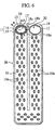
- Fig. 6 shows an inner surface of a tube plate 2a
- Fig. 7 is a magnified perspective view of an inlet header chamber 11 of the tube plate 2a
- Fig. 8 is a magnified view of an inner surface of the inlet header chamber 11 of the tube plate 2a
- Fig. 9 is a sectional view taken along a line IX-IX in Fig. 6
- Fig. 10 is a sectional view taken along a line X-X in Fig. 6,
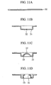
- Figs. 11(a) to 11(d) show steps for explaining a forming procedure of the inlet header chamber 11.
- the evaporator 1A mainly includes laminated tubes 2, corrugated fins 3 disposed between adjacent tubes 2, a refrigerant inlet pipe 4 connected to one of outermost ends of the laminated tubes 2, and a refrigerant outlet pipe 5 connected to the other outermost end of the laminated tubes 2.
- Each tube 2 includes a pair of tube plates 2a and 2a which are opposed to and connected to each other. As shown in Fig. 6, the tube 2 is formed therein with a U-shaped refrigerant passage 10, an inlet header chamber 11 which is in communication with one end of the refrigerant passage 10, and an outlet header chamber 12 which is in communication with the other end of the refrigerant passage 10.
- the inlet header chamber 11 and the outlet header chamber 12 are located above the refrigerant passage 10.
- a large number of projections 10a are disposed in position in the tube 2.
- the inlet header chamber 11 is partitioned by a partition wall 13 which projects in a substantially elliptic cylindrical shape, into inside inner header chambers 14 and outer header chambers 15 located at outer periphery of the inner header chambers 14. That is, the inner header chamber 14 is defined by the partition wall 13, and the outer header chamber 15 is defined outside the inner header chamber 14.
- the inner header chambers 14 between the butted tube plates 2a are opened through communication holes 16, and the inner header chambers 14 of the adjacent tubes 2 are in communication with each other.
- an assembly of the inner header chambers 14 forms a header inlet tank chamber 17.
- the refrigerant inlet pipe 4 is connected to the header inlet tank chamber 17.
- the header inlet tank chamber 17 can store a given amount of refrigerant in its lower portion and thus, the header inlet tank chamber 17 functions as a refrigerant supplier, commonly used for by the tubes 2. As will be described later, the header inlet tank chamber 17 can store refrigerant having substantially the same liquid level L in all the inner header chambers 14.
- the outer header chamber 15 is formed over the entire periphery of the inner header chamber 14, and a lower portion of the outer header chamber 15 is in communication with the refrigerant passage 10.
- Each partition wall 13 is provided at its three height positions with refrigerant through holes 18a, 18b and 18c which are laterally symmetric with respect to a center of the partition wall 13. More specifically, as shown in Figs. 7 and 8, the refrigerant through holes 18a, 18b and 18c are two lower holes 18a, two intermediate holes 18b and two upper holes 18c.
- Each lower hole 18a is located above a lowermost point a in the inner header chamber 14 and lower than a center position O of the inner header chamber 14.
- Each intermediate hole 18b is located at substantially the same level as that of the center position O of the inner header chamber 14.
- Each upper hole 18c is located above the center position O of the inner header chamber 14.
- the lower hole 18a is located such that a cross section area of the inner header chamber 14 lower than a horizontal line H which intersects with the lower holes 18a is one-third of the entire cross section area of the inner header chamber 14.
- the term “low”, “lower”, or “below” means a direction same as a gravity direction D as depicted by an arrow D in Fig. 8, and the term “high”, “upper”, or “above” means a direction opposite to the gravity direction D .
- a vertical (plumb) line P is in parallel to the gravity direction D .
- the outlet header chamber 12 is formed as a single space having an elliptic section. Each outlet header chamber 12 is opened through a communication hole 19. The adjacent outlet header chambers 12 of the tube 2 are in communication with each other through the communication hole 19. An assembly of the outlet header chambers 12 forms a header outlet tank chamber 20. The refrigerant outlet pipe 5 is connected to the header outlet tank chamber 20.
- the refrigerant from the refrigerant inlet pipe 4 flows into the header inlet tank chamber 17, and flows into the refrigerant passage 10 from the inner header chamber 14 of each tube 2 through the through holes 18a, 18b and 18c and the outer header chamber 15. Then, the refrigerant flows through each U-shaped refrigerant passage 10. During this process, the refrigerant exchanges heat with fluid outside the refrigerant passage.
- the refrigerant flowing through the refrigerant passage 10 then flows into the header outlet tank chamber 20 from the outlet header chamber 12 of each tube 2, and merges with another refrigerant which has circulated through another refrigerant passage 10 of another tube 2, and flows out from the refrigerant outlet pipe 5.
- the refrigerant is supplied from the inner header chamber 14 of each tube 2 to the refrigerant passage 10 through the outer header chamber 15.
- a specific gravity of liquid phase refrigerant A is large and a specific gravity of gas phase refrigerant B is relatively small.
- the liquid phase refrigerant A is stored in an entire lower region of the inner header chamber 14, and the gas phase refrigerant B is stored in the entire upper region of the inner header chamber 14.
- the header inlet tank chamber 17 functions as a refrigerant supplier, commonly used by all the tubes 2.
- refrigerant is always stored in the header inlet tank chamber 17 at a constant level, even if the flow rate of the refrigerant is small, the refrigerant is equally distributed in the common refrigerant supplier, and the liquid phase refrigerant A is equally supplied to the refrigerant passages 10 of the tubes 2.
- the gas phase refrigerant B stored in the inner header chamber 14 is allowed to flow out mainly by gas pressure from the intermediate holes 18b and the upper holes 18c from which the liquid phase refrigerant A does not flow out. Since the intermediate holes 18b and the upper holes 18c function as filters with respect to the gas flow, the refrigerant is released into the outer header chambers 15 of the tubes 2 substantially equally from the intermediate holes 18b and the upper holes 18c of the tubes 2. Since the gas phase refrigerant B and the liquid phase refrigerant A are less prone to be mixed with each other and they flow out from different holes, the liquid phase refrigerant A stored in the inner header chamber 14 is discharged almost without being affected by pressure of the gas phase refrigerant B or variation of the pressure. Thus, the refrigerant can be distributed to the refrigerant passages 10 substantially equally irrespective of the flow rate of the refrigerant, and the heat exchange efficiency can be enhanced.
- the refrigerant through holes 18a, 18b and 18c (lower holes 18a, intermediate holes 18b and upper holes 18c) are located at three levels with respect to the liquid level along a circumference part of the inner header chamber 14, liquid phase refrigerant A flows out mainly from the lower holes 18a, and gas phase refrigerant B flows out mainly from the intermediate holes 18b and the upper holes 18c. Therefore, the liquid phase refrigerant A is hardly affected by flow resistance and pressure variation of the gas phase refrigerant B , and this enhances the uniform distribution of refrigerant to the refrigerant passages 10.
- the lower holes 18a are located at such positions that the cross section area of the inner header chamber 14 lower than the horizontal line H which forms point of intersection of the lower holes 18a is one-third of the entire cross section area of the inner header chamber 14 or less than that.
- the refrigerant through holes 18a, 18b and 18c are provided laterally symmetrically with respect to the center of the inner header chamber 14. That is, the left and right refrigerant holes are disposed substantially in parallel to the horizontal line H. Therefore, the liquid phase refrigerant A and the gas phase refrigerant B can flow out respectively from the left and right positions of the inner header chamber 14. Thus, the liquid phase refrigerant A and the gas phase refrigerant B can smoothly flow out from the inner header chamber 14. Pressures of the refrigerant in the left and right refrigerant holes in the inner header chamber 14 and the outer header chamber 15 can be prevented from being different from each other.
- FIG. 11A A flat plate 30 shown in Fig. 11A is subjected to a push-out operation and a punch-out operation.
- a push-out operation As shown in Fig. 11B, a push-out portion 31 corresponding to an outer periphery of the outer header chamber 15 is formed.
- the push-out portion 31 is formed at its center position with a hole 32.
- an inner periphery of the push-out portion 31 is formed with a return-inclined wall 33 by a pushing and bending operation.
- the return-inclined wall 33 is then further pushed and bent to form the partition wall 13 by a bending operation. With this bending operation, the hole 32 is increased in diameter and the communication hole 16 is formed. Lastly, predetermined portions (shown with hatching in the drawing) of the partition wall 13 are cut to form the through holes 18a, 18b and 18c (shown in Fig. 7 and the like).
- the refrigerant holding projections can be formed without generating a crack.
- the liquid phase refrigerant flowing into the inner header chamber is stored in the entire lower region of the inner header chamber, and the gas phase refrigerant is stored in the entire upper region of the inner header chamber. If the liquid level of the liquid phase refrigerant A becomes higher than the lower refrigerant hole, the liquid phase refrigerant flows out from the lower refrigerant hole of the tubes only by the overflow. Therefore, even when the flow rate of the refrigerant is small, the liquid phase refrigerant equally flows out into the refrigerant passages of the tubes. On the other hand, the gas phase refrigerant stored in the inner header chamber is allowed to flow out by gas pressure from the upper refrigerant holes from which the liquid phase refrigerant does not flow out.
- the refrigerant flows out into the refrigerant passages of the tubes substantially equally. Since the gas phase refrigerant flows out basically through a hole different from the liquid phase refrigerant, the liquid phase refrigerant stored in the inner header chamber is discharged almost without being affected by dynamic pressure of the gas phase refrigerant. Thus, it is possible to distribute the refrigerant substantially equally to the refrigerant passages irrespective of the flow rate of the refrigerant, and to enhance the heat exchanging efficiency.
- the liquid phase refrigerant flows out mainly from the lower holes and the gas phase refrigerant flows out mainly from the intermediate holes and the upper holes. Therefore, the liquid phase refrigerant is equally distributed to the refrigerant passages almost without being affected by dynamic pressure of the gas phase refrigerant.
- Figs. 12 to 15 show a second embodiment of the present invention.
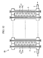
- Fig. 12 is a front view of an evaporator 1B
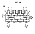
- Fig. 13 is a sectional view of an essential portion of the evaporator 1B
- Fig. 14 shows an inner surface of the tube plate 2a
- Fig. 15 is a magnified view of the inner surface of the inlet header chamber 11 of the tube plate 2a.
- positions of the inlet header chamber 11 and the outlet header chamber 12 are vertically reversed as compared with the first embodiment. That is, the inlet header chamber 11 and the outlet header chamber 12 are located below the refrigerant passage 10.
- the inlet header chamber 11 is partitioned by the partition wall 13 into the inner header chamber 14 and the outer header chamber 15.
- the partition wall 13 is provided at its three levels with the refrigerant through holes 18a, 18b and 18c which are laterally symmetric with respect to a center of the partition wall 13.
- the refrigerant through holes 18a, 18b and 18c are located in the same manner as that of the first embodiment. That is, as shown in Figs. 14 and 15, the refrigerant through holes 18a, 18b and 18c are two upper holes 18c, two intermediate holes 18b and two lower holes 18a. Each upper hole 18c is located lower than an uppermost point b in the inner header chamber 14 and higher than the center position O of the inner header chamber 14.
- Each intermediate hole 18b is located at substantially the same height as the center position O of the inner header chamber 14.
- Each lower hole 18a is located lower than the center position O of the inner header chamber 14. It is preferable that a cross section area of the inner header chamber 14 located higher than the horizontal line H which intersects with the upper holes 18c is one-third of or less than the entire cross section area of the inner header chamber 14.
- the refrigerant from the refrigerant inlet pipe 4 flows into the header inlet tank chamber 17, and flows into the refrigerant passage 10 from the inner header chamber 14 of each tube 2 through the through holes 18a, 18b and 18c and the outer header chamber 15. Then, the refrigerant flows through each U-shaped refrigerant passage 10. During this process, the refrigerant exchanges heat with fluid outside the refrigerant passage.
- the refrigerant flowing through the refrigerant passage 10 then flows into the header outlet tank chamber 20 from the outlet header chamber 12 of each tube 2, and merges with another refrigerant which has circulated another refrigerant passage 10 of another tube 2, and flows out from the refrigerant outlet pipe 5.
- the refrigerant is supplied from the inner header chamber 14 of each tube 2 to the refrigerant passage 10 through the outer header chamber 15. This operation will be explained in detail.
- a specific gravity of liquid phase refrigerant A is larger than that of gas phase refrigerant B is light.
- the liquid phase refrigerant A is stored in an entire lower region of the inner header chamber 14, and the gas phase refrigerant B is stored in the entire upper region of the inner header chamber 14.
- the gas phase refrigerant flows out into the respective outer header chambers 15 through the upper holes 18c of the tubes 2 only by the overflow. Therefore, even when the flow rate of the refrigerant is small, gas phase refrigerant flows out into the refrigerant passages 10 of the tubes 2 substantially equally.
- the liquid phase refrigerant A in the inner header chamber 14 flows out into the outer header chambers 15 mainly through the intermediate holes 18b and the lower holes 18a.
- the gas phase refrigerant B flows out from the inner header chamber 14 by the overflow, the liquid phase refrigerant A is not affected by flowing resistance and pressure variation of gas phase refrigerant B and thus, the height of an interface between the gas phase and liquid phase can be maintained even. Therefore, the refrigerant is equally distributed to the outer header chambers 15 of the tubes 2. Thus, the refrigerant can be distributed to the refrigerant passages 10 substantially equally irrespective of the flow rate of the refrigerant, and the heat exchange efficiency can be enhanced.
- the refrigerant through holes 18a, 18b and 18c include the upper holes 18c located lower than an uppermost point b in the inner header chamber 14 and higher than the center position O of the inner header chamber 14, the intermediate holes 18b located at substantially the same height as the center position O of the inner header chamber 14, and the lower holes 18a located lower than the center position O of the inner header chamber 14. Therefore, mainly the liquid phase refrigerant A flows out from the lower holes 18a and the intermediate holes 18b, and mainly the gas phase refrigerant B flows out from the upper holes 18c. As a result, the liquid phase refrigerant A is equally distributed to the refrigerant passages 10 almost without being affected by the pressure and variation of the pressure of the gas phase refrigerant B .
- the upper holes 18c are located at such positions that the cross section area of the inner header chamber 14 located higher than the horizontal line H which intersects with the upper holes 18c is one-third of the entire cross section area of the inner header chamber 14 or less than that. Therefore, one-third of gas phase refrigerant B is stored in the inner header chamber 14, and it can be expected that the gas phase refrigerant B flows out stably by the overflow.
- the refrigerant through holes 18a, 18b and 18c are located laterally symmetric with respect to the center of the inner header chamber 14. Therefore, the liquid phase refrigerant A and gas phase refrigerant B can flow out from left and right positions of the inner header chamber 14. Thus, the liquid phase refrigerant A and gas phase refrigerant B can smoothly flow out from the inner header chamber 14. It is possible to prevent generation of uneven pressure at left and right positions in the inner header chamber 14 and the outer header chamber 15.
- the liquid phase refrigerant is stored in the entire lower region in the inner header chamber and the gas phase refrigerant is stored in the entire upper region in the inner header chamber. If the position of the gas phase becomes lower than the upper refrigerant hole, the gas phase refrigerant flows out from the upper refrigerant holes of the tubes only by the overflow. Thus, even when the flow rate of the refrigerant is small, gas phase refrigerant flows out into the refrigerant passages of the tubes substantially equally.
- the liquid phase refrigerant in the inner header chamber flows out into the outer header chamber through the lower refrigerant holes.
- the liquid level is equalized almost without being affected by drift of gas phase, and the liquid phase refrigerant is distributed to the outer header chambers of the tubes equally.
- the refrigerant can be distributed to the refrigerant passages substantially equally irrespective of the flow rate of the refrigerant, and the heat exchange efficiency can be enhanced.
- liquid phase refrigerant flows out from the lower holes and the intermediate holes, and mainly the gas phase refrigerant flows out from the upper holes.
- the liquid phase refrigerant is distributed to the refrigerant passages equally almost without being affected by dynamic pressure of gas phase.
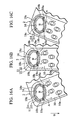
- Figs. 16A to 16C show a modification of the first embodiment.
- Fig. 16A shows an inner surface of an essential portion of the tube 2 which is inclined at an angle of -20°.
- Fig. 16B shows the inner surface of an essential portion of the tube 2 which is inclined at an angle of 0°.
- Fig. 16C shows the inner surface of an essential portion of the tube 2 which is inclined at an angle of +20°.
- the positions of the six refrigerant through holes 18a, 18b and 18c at three positions are changed in accordance with the inclination angle of the tube 2.
- the left and right through holes are disposed substantially in parallel to the horizontal line H .
- the same amount of gas phase refrigerant B can be stored in the inner header chamber 14 irrespective of the angle of the disposed heat exchanger.
- the present invention is not limited to this configuration only if these through holes are provided at least at two levels.
- total of six refrigerant holes are provided at three height positions. More preferably, total of eight or more refrigerant holes should be provided at four or more height positions.
- two refrigerant holes are used for discharging the liquid phase refrigerant A
- six or more refrigerant holes are used for discharging the gas phase refrigerant B
- a ratio of the liquid phase refrigerant A and the gas phase refrigerant B can be satisfied.
- cross section of the inner header chamber 14 is substantially elliptic in the embodiments, the cross section shape is not limited, and circular, rectangular or triangular cross section may also be employed.
- the refrigerant passage 10 in the tube 2 is U-shaped in the embodiments, the present invention is obviously applied to the refrigerant passage 10 with a straight shape or any other shapes.
Landscapes
- Engineering & Computer Science (AREA)
- Physics & Mathematics (AREA)
- Thermal Sciences (AREA)
- Mechanical Engineering (AREA)
- General Engineering & Computer Science (AREA)
- Details Of Heat-Exchange And Heat-Transfer (AREA)
- Heat-Exchange Devices With Radiators And Conduit Assemblies (AREA)
Abstract
Description
Claims (13)
- An evaporator (1A) having a plurality of laminated tubes (2), a refrigerant passage (10) formed in each tube (2), an inlet header chamber (11) which is in communication with one end of the refrigerant passage (10), and an outlet header chamber (12) which is in communication with the other end of the refrigerant passage (10), the evaporator comprising:an inner header chamber (14) defined in the inlet header chamber by a partition wall (13);an outer header chamber (15) defined by an outer periphery of the inner header chamber by the partition wall, the outer header chamber (15) being in communication with the refrigerant passage (10); anda common refrigerant supplier (17) formed by an assembly of the inner header chambers, whereinthe refrigerant supplier stores refrigerant having substantially the same liquid level (H) in all the inner header chambers.
- The evaporator according to claim 1, further comprisinga plurality of refrigerant through holes (18a, 18b and 18c) formed in the partition wall, the refrigerant through holes being formed at two levels, whereinthe refrigerant which flows out from the refrigerant supplier is supplied to the refrigerant passages through the outer header chambers.
- The evaporator according to claim 2, whereinthe refrigerant supplier is disposed above the refrigerant passage.
- The evaporator according to claim 3, whereinthe refrigerant through holes are disposed higher than a lowermost position (a) of the inner header chamber.
- The evaporator according to claim 3, whereinthe refrigerant through holes are disposed above and below a center position of the inner header chamber.
- The evaporator according to claim 3, whereinthe refrigerant through holes are lower holes (18a) located below the center position of the inner header chamber, intermediate holes (18b) located at substantially the same level as the center position, and upper holes (18c) located above the center position.
- The evaporator according to claim 6, whereinthe lower holes are provided at a liquid level at which a cross section area of the inner header chamber occupied by liquid phase refrigerant is one-third of the cross section area of the inner header chamber or less.
- The evaporator according to claim 6, whereinthe refrigerant through holes are provided on a one-pair by one-pair basis at locations opposed to each other at the same level.
- The evaporator according to claim 2, whereinthe refrigerant supplier is disposed below each refrigerant passage.
- The evaporator according to claim 9, whereinthe refrigerant through holes are located below an uppermost position (b) of the inner header chamber.
- The evaporator according to claim 9, whereinthe refrigerant through holes are disposed above and below the center position of the inner header chamber.
- The evaporator according to claim 9, whereinthe refrigerant through holes are lower holes (18a) located below the center position of the inner header chamber, intermediate holes (18b) located at substantially the same level as the center position, and upper holes (18c) located above the center position.
- The evaporator according to claim 12, whereinthe refrigerant through holes are provided on a one-pair by one-pair basis at locations opposed to each other at the same level.
Applications Claiming Priority (2)
| Application Number | Priority Date | Filing Date | Title |
|---|---|---|---|
| JP2003114217 | 2003-04-18 | ||
| JP2003114217A JP4213504B2 (en) | 2003-04-18 | 2003-04-18 | Evaporator |
Publications (2)
| Publication Number | Publication Date |
|---|---|
| EP1469268A2 true EP1469268A2 (en) | 2004-10-20 |
| EP1469268A3 EP1469268A3 (en) | 2005-10-19 |
Family
ID=32906087
Family Applications (1)
| Application Number | Title | Priority Date | Filing Date |
|---|---|---|---|
| EP04009012A Withdrawn EP1469268A3 (en) | 2003-04-18 | 2004-04-15 | Evaporator |
Country Status (3)
| Country | Link |
|---|---|
| US (1) | US6868696B2 (en) |
| EP (1) | EP1469268A3 (en) |
| JP (1) | JP4213504B2 (en) |
Cited By (2)
| Publication number | Priority date | Publication date | Assignee | Title |
|---|---|---|---|---|
| WO2006043864A1 (en) * | 2004-10-21 | 2006-04-27 | Alfa Laval Corporate Ab | A plate heat exchanger and a plate module |
| WO2014116660A1 (en) * | 2013-01-24 | 2014-07-31 | Alcoil Usa Llc | Heat exchanger |
Families Citing this family (13)
| Publication number | Priority date | Publication date | Assignee | Title |
|---|---|---|---|---|
| DE10352880A1 (en) * | 2003-11-10 | 2005-06-09 | Behr Gmbh & Co. Kg | Heat exchanger, in particular charge air / coolant radiator |
| DE10352881A1 (en) | 2003-11-10 | 2005-06-09 | Behr Gmbh & Co. Kg | Heat exchanger, in particular charge air / coolant radiator |
| NO320779B1 (en) * | 2004-06-14 | 2006-01-30 | Inst Energiteknik | Innlopsinnretning |
| WO2008064199A1 (en) * | 2006-11-22 | 2008-05-29 | Johnson Controls Technology Company | Multichannel evaporator with flow separating manifold |
| WO2008064247A1 (en) * | 2006-11-22 | 2008-05-29 | Johnson Controls Technology Company | Multi-function multichannel heat exchanger |
| KR101568200B1 (en) * | 2006-11-22 | 2015-11-11 | 존슨 컨트롤스 테크놀러지 컴퍼니 | Multichannel heat exchanger with dissimilar tube spacing |
| US20090025405A1 (en) * | 2007-07-27 | 2009-01-29 | Johnson Controls Technology Company | Economized Vapor Compression Circuit |
| WO2009018150A1 (en) * | 2007-07-27 | 2009-02-05 | Johnson Controls Technology Company | Multichannel heat exchanger |
| WO2009029506A1 (en) * | 2007-08-24 | 2009-03-05 | Johnson Controls Technology Company | Control system |
| EP2315995B1 (en) * | 2008-04-17 | 2019-06-12 | Dana Canada Corporation | U-flow heat exchanger |
| US8439104B2 (en) * | 2009-10-16 | 2013-05-14 | Johnson Controls Technology Company | Multichannel heat exchanger with improved flow distribution |
| TR201911112T4 (en) * | 2013-12-10 | 2019-08-21 | Swep Int Ab | Heat exchanger with improved flow. |
| JP7505400B2 (en) * | 2020-12-25 | 2024-06-25 | 株式会社富士通ゼネラル | Heat exchanger |
Family Cites Families (18)
| Publication number | Priority date | Publication date | Assignee | Title |
|---|---|---|---|---|
| GB1571048A (en) * | 1976-03-09 | 1980-07-09 | Nihon Radiator Co | Heat exchanger |
| US4723601A (en) * | 1985-03-25 | 1988-02-09 | Nippondenso Co., Ltd. | Multi-layer type heat exchanger |
| AU604361B2 (en) * | 1988-08-09 | 1990-12-13 | Nippondenso Co. Ltd. | Plate type heat exchanger |
| US5172759A (en) * | 1989-10-31 | 1992-12-22 | Nippondenso Co., Ltd. | Plate-type refrigerant evaporator |
| US5137082A (en) * | 1989-10-31 | 1992-08-11 | Nippondenso Co., Ltd. | Plate-type refrigerant evaporator |
| JPH0776651B2 (en) * | 1990-02-06 | 1995-08-16 | 昭和アルニミウム株式会社 | Multilayer evaporator |
| JPH04177094A (en) * | 1990-11-13 | 1992-06-24 | Sanden Corp | Laminated type heat exchanger |
| JP2751657B2 (en) * | 1991-04-25 | 1998-05-18 | 株式会社日立製作所 | Stacked heat exchanger |
| US5409056A (en) * | 1992-05-11 | 1995-04-25 | General Motors Corporation | U-flow tubing for evaporators with bump arrangement for optimized forced convection heat exchange |
| KR100353020B1 (en) * | 1993-12-28 | 2003-01-10 | 쇼와 덴코 가부시키가이샤 | Multilayer Heat Exchanger |
| JP3635691B2 (en) * | 1994-10-13 | 2005-04-06 | 株式会社デンソー | Refrigerant evaporator and vehicle air conditioner using the same |
| JP2934392B2 (en) * | 1995-02-07 | 1999-08-16 | サンデン株式会社 | Heat exchanger |
| JPH08271091A (en) * | 1995-03-30 | 1996-10-18 | Nippondenso Co Ltd | Refrigerant evaporator |
| JP3085137B2 (en) * | 1995-04-21 | 2000-09-04 | 株式会社デンソー | Stacked heat exchanger |
| DE19543149C2 (en) * | 1995-11-18 | 2000-09-14 | Behr Gmbh & Co | Heat exchangers, especially refrigerant evaporators |
| JPH10292995A (en) * | 1997-02-21 | 1998-11-04 | Zexel Corp | Stacked heat exchanger |
| JP3629900B2 (en) * | 1997-07-04 | 2005-03-16 | 株式会社デンソー | Heat exchanger |
| US5855240A (en) * | 1998-06-03 | 1999-01-05 | Ford Motor Company | Automotive heat exchanger |
-
2003
- 2003-04-18 JP JP2003114217A patent/JP4213504B2/en not_active Expired - Fee Related
-
2004
- 2004-04-15 EP EP04009012A patent/EP1469268A3/en not_active Withdrawn
- 2004-04-16 US US10/826,900 patent/US6868696B2/en not_active Expired - Fee Related
Cited By (3)
| Publication number | Priority date | Publication date | Assignee | Title |
|---|---|---|---|---|
| WO2006043864A1 (en) * | 2004-10-21 | 2006-04-27 | Alfa Laval Corporate Ab | A plate heat exchanger and a plate module |
| WO2014116660A1 (en) * | 2013-01-24 | 2014-07-31 | Alcoil Usa Llc | Heat exchanger |
| US9459057B2 (en) | 2013-01-24 | 2016-10-04 | Alcoll USA LLC | Heat exchanger |
Also Published As
| Publication number | Publication date |
|---|---|
| EP1469268A3 (en) | 2005-10-19 |
| JP4213504B2 (en) | 2009-01-21 |
| JP2004317079A (en) | 2004-11-11 |
| US20040206488A1 (en) | 2004-10-21 |
| US6868696B2 (en) | 2005-03-22 |
Similar Documents
| Publication | Publication Date | Title |
|---|---|---|
| US6868696B2 (en) | Evaporator | |
| AU2002217510B8 (en) | Layered heat exchangers | |
| KR101826365B1 (en) | A heat exchanger | |
| US7472563B2 (en) | Submerged evaporator with integrated heat exchanger | |
| US6920916B2 (en) | Layered heat exchangers | |
| CN101782297A (en) | Heat exchanger | |
| US20180073819A1 (en) | Heat exchanger, header for the same and manufacturing method thereof | |
| CN112283983B (en) | A falling film evaporator and air conditioning system | |
| CN1470841A (en) | laminated heat exchanger | |
| CN119063559A (en) | A header assembly and a heat exchanger | |
| EP4407269A1 (en) | Falling film evaporator | |
| JP3214272B2 (en) | Condenser | |
| JP2016176615A (en) | Parallel flow type heat exchanger | |
| CN100535555C (en) | Heat exchanger | |
| JPS633153A (en) | Refrigerant evaporator | |
| JPH01305275A (en) | Refrigerant evaporator | |
| JP6520563B2 (en) | Refrigerant evaporator | |
| JP2020159681A (en) | Heat exchanger | |
| CN110822772A (en) | Falling film evaporator | |
| WO2002081998A1 (en) | Heat exchanger manifold | |
| CN114396743A (en) | Liquid distributor of falling film heat exchanger | |
| US20250264283A1 (en) | Fluid distributor for an inlet header of a heat exchanger | |
| JP6956868B2 (en) | Shell and tube heat exchanger | |
| JP2005061778A (en) | Evaporator | |
| KR20030019684A (en) | Heat exchanger |
Legal Events
| Date | Code | Title | Description |
|---|---|---|---|
| PUAI | Public reference made under article 153(3) epc to a published international application that has entered the european phase |
Free format text: ORIGINAL CODE: 0009012 |
|
| AK | Designated contracting states |
Kind code of ref document: A2 Designated state(s): AT BE BG CH CY CZ DE DK EE ES FI FR GB GR HU IE IT LI LU MC NL PL PT RO SE SI SK TR |
|
| AX | Request for extension of the european patent |
Extension state: AL HR LT LV MK |
|
| PUAL | Search report despatched |
Free format text: ORIGINAL CODE: 0009013 |
|
| AK | Designated contracting states |
Kind code of ref document: A3 Designated state(s): AT BE BG CH CY CZ DE DK EE ES FI FR GB GR HU IE IT LI LU MC NL PL PT RO SE SI SK TR |
|
| AX | Request for extension of the european patent |
Extension state: AL HR LT LV MK |
|
| RIC1 | Information provided on ipc code assigned before grant |
Ipc: 7F 25B 39/02 B Ipc: 7F 28F 9/02 B Ipc: 7F 28D 1/03 A |
|
| 17P | Request for examination filed |
Effective date: 20051219 |
|
| AKX | Designation fees paid |
Designated state(s): DE FR GB |
|
| STAA | Information on the status of an ep patent application or granted ep patent |
Free format text: STATUS: THE APPLICATION HAS BEEN WITHDRAWN |
|
| 17Q | First examination report despatched |
Effective date: 20091112 |
|
| 18W | Application withdrawn |
Effective date: 20091112 |