EP1469177A1 - A system for transmitting drive from the crankshaft of an internal combustion engine of a motor vehicle to a group of auxiliary devices - Google Patents
A system for transmitting drive from the crankshaft of an internal combustion engine of a motor vehicle to a group of auxiliary devices Download PDFInfo
- Publication number
- EP1469177A1 EP1469177A1 EP04008957A EP04008957A EP1469177A1 EP 1469177 A1 EP1469177 A1 EP 1469177A1 EP 04008957 A EP04008957 A EP 04008957A EP 04008957 A EP04008957 A EP 04008957A EP 1469177 A1 EP1469177 A1 EP 1469177A1
- Authority
- EP
- European Patent Office
- Prior art keywords
- crankshaft
- internal combustion
- combustion engine
- pulley
- clutch
- Prior art date
- Legal status (The legal status is an assumption and is not a legal conclusion. Google has not performed a legal analysis and makes no representation as to the accuracy of the status listed.)
- Granted
Links
Images
Classifications
-
- F—MECHANICAL ENGINEERING; LIGHTING; HEATING; WEAPONS; BLASTING
- F02—COMBUSTION ENGINES; HOT-GAS OR COMBUSTION-PRODUCT ENGINE PLANTS
- F02N—STARTING OF COMBUSTION ENGINES; STARTING AIDS FOR SUCH ENGINES, NOT OTHERWISE PROVIDED FOR
- F02N11/00—Starting of engines by means of electric motors
- F02N11/003—Starting of engines by means of electric motors said electric motor being also used as a drive for auxiliaries, e.g. for driving transmission pumps or fuel pumps during engine stop
-
- F—MECHANICAL ENGINEERING; LIGHTING; HEATING; WEAPONS; BLASTING
- F02—COMBUSTION ENGINES; HOT-GAS OR COMBUSTION-PRODUCT ENGINE PLANTS
- F02B—INTERNAL-COMBUSTION PISTON ENGINES; COMBUSTION ENGINES IN GENERAL
- F02B63/00—Adaptations of engines for driving pumps, hand-held tools or electric generators; Portable combinations of engines with engine-driven devices
- F02B63/04—Adaptations of engines for driving pumps, hand-held tools or electric generators; Portable combinations of engines with engine-driven devices for electric generators
-
- F—MECHANICAL ENGINEERING; LIGHTING; HEATING; WEAPONS; BLASTING
- F02—COMBUSTION ENGINES; HOT-GAS OR COMBUSTION-PRODUCT ENGINE PLANTS
- F02B—INTERNAL-COMBUSTION PISTON ENGINES; COMBUSTION ENGINES IN GENERAL
- F02B67/00—Engines characterised by the arrangement of auxiliary apparatus not being otherwise provided for, e.g. the apparatus having different functions; Driving auxiliary apparatus from engines, not otherwise provided for
- F02B67/04—Engines characterised by the arrangement of auxiliary apparatus not being otherwise provided for, e.g. the apparatus having different functions; Driving auxiliary apparatus from engines, not otherwise provided for of mechanically-driven auxiliary apparatus
- F02B67/06—Engines characterised by the arrangement of auxiliary apparatus not being otherwise provided for, e.g. the apparatus having different functions; Driving auxiliary apparatus from engines, not otherwise provided for of mechanically-driven auxiliary apparatus driven by means of chains, belts, or like endless members
-
- F—MECHANICAL ENGINEERING; LIGHTING; HEATING; WEAPONS; BLASTING
- F02—COMBUSTION ENGINES; HOT-GAS OR COMBUSTION-PRODUCT ENGINE PLANTS
- F02N—STARTING OF COMBUSTION ENGINES; STARTING AIDS FOR SUCH ENGINES, NOT OTHERWISE PROVIDED FOR
- F02N11/00—Starting of engines by means of electric motors
- F02N11/04—Starting of engines by means of electric motors the motors being associated with current generators
-
- F—MECHANICAL ENGINEERING; LIGHTING; HEATING; WEAPONS; BLASTING
- F02—COMBUSTION ENGINES; HOT-GAS OR COMBUSTION-PRODUCT ENGINE PLANTS
- F02N—STARTING OF COMBUSTION ENGINES; STARTING AIDS FOR SUCH ENGINES, NOT OTHERWISE PROVIDED FOR
- F02N11/00—Starting of engines by means of electric motors
- F02N11/08—Circuits specially adapted for starting of engines
- F02N11/0814—Circuits specially adapted for starting of engines comprising means for controlling automatic idle-start-stop
-
- F—MECHANICAL ENGINEERING; LIGHTING; HEATING; WEAPONS; BLASTING
- F02—COMBUSTION ENGINES; HOT-GAS OR COMBUSTION-PRODUCT ENGINE PLANTS
- F02N—STARTING OF COMBUSTION ENGINES; STARTING AIDS FOR SUCH ENGINES, NOT OTHERWISE PROVIDED FOR
- F02N15/00—Other power-operated starting apparatus; Component parts, details, or accessories, not provided for in, or of interest apart from groups F02N5/00 - F02N13/00
- F02N15/02—Gearing between starting-engines and started engines; Engagement or disengagement thereof
- F02N15/022—Gearing between starting-engines and started engines; Engagement or disengagement thereof the starter comprising an intermediate clutch
- F02N15/023—Gearing between starting-engines and started engines; Engagement or disengagement thereof the starter comprising an intermediate clutch of the overrunning type
-
- F—MECHANICAL ENGINEERING; LIGHTING; HEATING; WEAPONS; BLASTING
- F02—COMBUSTION ENGINES; HOT-GAS OR COMBUSTION-PRODUCT ENGINE PLANTS
- F02B—INTERNAL-COMBUSTION PISTON ENGINES; COMBUSTION ENGINES IN GENERAL
- F02B63/00—Adaptations of engines for driving pumps, hand-held tools or electric generators; Portable combinations of engines with engine-driven devices
- F02B63/04—Adaptations of engines for driving pumps, hand-held tools or electric generators; Portable combinations of engines with engine-driven devices for electric generators
- F02B63/042—Rotating electric generators
-
- Y—GENERAL TAGGING OF NEW TECHNOLOGICAL DEVELOPMENTS; GENERAL TAGGING OF CROSS-SECTIONAL TECHNOLOGIES SPANNING OVER SEVERAL SECTIONS OF THE IPC; TECHNICAL SUBJECTS COVERED BY FORMER USPC CROSS-REFERENCE ART COLLECTIONS [XRACs] AND DIGESTS
- Y02—TECHNOLOGIES OR APPLICATIONS FOR MITIGATION OR ADAPTATION AGAINST CLIMATE CHANGE
- Y02T—CLIMATE CHANGE MITIGATION TECHNOLOGIES RELATED TO TRANSPORTATION
- Y02T10/00—Road transport of goods or passengers
- Y02T10/10—Internal combustion engine [ICE] based vehicles
- Y02T10/40—Engine management systems
-
- Y—GENERAL TAGGING OF NEW TECHNOLOGICAL DEVELOPMENTS; GENERAL TAGGING OF CROSS-SECTIONAL TECHNOLOGIES SPANNING OVER SEVERAL SECTIONS OF THE IPC; TECHNICAL SUBJECTS COVERED BY FORMER USPC CROSS-REFERENCE ART COLLECTIONS [XRACs] AND DIGESTS
- Y10—TECHNICAL SUBJECTS COVERED BY FORMER USPC
- Y10T—TECHNICAL SUBJECTS COVERED BY FORMER US CLASSIFICATION
- Y10T74/00—Machine element or mechanism
- Y10T74/13—Machine starters
- Y10T74/131—Automatic
- Y10T74/134—Clutch connection
Definitions
- the present invention relates to a system for transmitting drive between the engine crankshaft of an internal combustion engine of a motor vehicle and a group of auxiliary devices provided with respective drive shafts and including an electric machine operable to function selectively as a generator and a motor.
- the subject of the invention is a transmission system of the type comprising
- a drive transmission system of this type is known, with an electromagnetically controlled clutch which is normally excited and engaged to couple the said pulley to the crankshaft for rotation with the internal combustion engine.
- This known system makes it possible to achieve the following functions or operative conditions:
- the known system described above has the disadvantage of requiring that the electromagnetic clutch remains permanently energised when the internal combustion engine is running.
- the prolonged energisation of this clutch involves a high consumption of electrical energy which negatively influences the overall energy balance.
- One object of the present invention is to provide a drive transmission system of the above-specified type, which makes it possible to overcome this disadvantage.
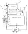
- a drive transmission system for transmitting motion between the crankshaft 2, of an internal combustion engine 3, of a motor vehicle (not shown) and a group of auxiliary devices generally indicated 4.
- this group of auxiliary devices 4 comprises a compressor 5, for an air conditioning system of the motor vehicle passenger compartment, and a reversible electric machine 6, operable to function selectively as a generator and an electric motor.
- This electric machine 6 is, for example, a three-phase asynchronous machine.
- the auxiliary devices 5 and 6 are provided with respective drive shafts 5a and 6a, on which are fitted respective pulleys 5b and 6b.
- the transmission system 1 comprises at least 1 transmission belt 7 which couples the pulley 5b and 6b of the auxiliary devices 5 and 6 for rotation with a pulley 8 operatively connectable to the crankshaft 2 of the internal combustion engine 3 in the ways which will be described hereinbelow.
- a friction clutch for example of the electromagnetically controlled type is indicated 9, and acts to control the coupling between the pulley 8 and the crankshaft 2 of the internal combustion engine 3 selectively.
- this clutch 9 comprises an excitation winding 10 of annular form disposed about the axis of the crankshaft after 2 of the internal combustion engine 3, and fixed to the engine 3.
- this overrun clutch 11 is formed in such a way that when the angular velocity of the crankshaft 2 of the internal combustion engine 3 is greater and, respectively, less than that of the pulley 8, this pulley 8 is capable of being driven to rotate by the crankshaft 2 and, respectively, becomes freely rotatable with respect to this crankshaft.
- the system 1 further includes a control unit ECU arranged to cause excitation of the winding 10 and the consequent engagement of the clutch 9 and activation of the electric machine 6 as a motor, when the internal combustion engine 3 is not running, that is for the purpose of hot starting the engine by means of the electric machine 6 operating as a motor.
- a control unit ECU arranged to cause excitation of the winding 10 and the consequent engagement of the clutch 9 and activation of the electric machine 6 as a motor, when the internal combustion engine 3 is not running, that is for the purpose of hot starting the engine by means of the electric machine 6 operating as a motor.
- control unit ECU is arranged for example to pilot a controlled bridge inventor circuit 12 (figure 1) connected to the electric machine 6 and to a rechargeable dc voltage source such as a battery 13.
- the unit ECU is conveniently also connected to a sensor 14 able to provide it with signals indicative of the speed of rotation of the crankshaft 2 of the internal combustion engine 3 and a sensor 15 operable to provide it with signals indicative of the temperature of this engine.
- the drive transmission system 1 described above with reference to figure 1 operates essentially in the following manner.
- the pulley 8 is capable of being driven to rotate by the crankshaft 2 of the internal combustion engine 3 by means of the overrun clutch 11. Rotation of the pulley 8 by means of the belt 7 causes rotation of the auxiliary devices 5 and 6.
- the electric machine 6 in particular can operate as a generator to recharge the battery 13.
- the control unit ECU can cause actuation, if required, of the compressor 5 of the air conditioning system by making the electric machine 6 operate as an electric motor (via the inverter 12).
- the torque is transmitted from the drive shaft 6a of the electric machine 6 to the drive shaft 5a of the compressor 5 by means of the belt 7 and the pulley 8 which is released from rotation with the crankshaft 2 of the internal combustion engine.
- the clutch 9 remains de energised and disengaged in these conditions.
- the control unit ECU can control engagement of the clutch 9 and coupling of the crankshaft 2 for rotation with the engine 3 to the pulley 8 when it is necessary to restart the internal combustion engine 3 hot, without resource to the specific electric starter motor, for example to achieve a so-called stop-start functioning mode for minimisation of fuel consumption and emissions.
- the control unit ECU causes functioning of the electric machine 6 as an electric motor so as to drive the crankshaft 2 of the internal combustion engine 3 into rotation by means of the belt 7 and the pulley 8.
- the system described above has the advantage of achieving an automatic coupling between the crankshaft of the internal combustion engine and the transmission belt 7 as soon as the speed of rotation of the engine 3 exceeds the speed of rotation of the pulley 8.
- the use of the clutch 9 is limited solely to the function of hot starting the internal combustion engine.
- This clutch 9 is moreover conveniently dimensioned only in relation to the torque necessary to achieve hot staring of the internal combustion engine, and this component is therefore relatively economical.
- the clutch 9 could be of the electro hydraulic controlled type.
Landscapes
- Engineering & Computer Science (AREA)
- Chemical & Material Sciences (AREA)
- Combustion & Propulsion (AREA)
- Mechanical Engineering (AREA)
- General Engineering & Computer Science (AREA)
- Devices For Conveying Motion By Means Of Endless Flexible Members (AREA)
- Control Of Vehicle Engines Or Engines For Specific Uses (AREA)
- Auxiliary Drives, Propulsion Controls, And Safety Devices (AREA)
- Valve-Gear Or Valve Arrangements (AREA)
- Electrical Control Of Air Or Fuel Supplied To Internal-Combustion Engine (AREA)
- Valve Device For Special Equipments (AREA)
- Lens Barrels (AREA)
Abstract
Description
- activation of the auxiliary devices (compressor of the air conditioning system, electric machine functioning as generator etc) whilst the internal combustion engine is running; the electromagnetically controlled clutch is excited and engaged;
- activation of the auxiliary devices, and in particular of the compressor of the air conditioning system, whilst the internal combustion engine is not running; in this case the electromagnetically controlled clutch is de-excited, and therefore disengaged, and the said electric machine is made to operate as a motor to drive the compressor in rotation by means of the said transmission belt; and
- re-starting of the internal combustion engine (hot) by means of the said electric machine, by operating as a motor, for example to achieve a so-called stop-start function; in this case the electromagnetically controlled clutch is excited and engaged to couple the said electric machine to the crankshaft of the internal combustion engine in the re-starting phase.
Claims (4)
- A device transmission system (1) between the crankshaft (2) of an internal combustion engine (3) of a motor vehicle and a group (4) of auxiliary devices provided with respective drive shafts (5a, 6a) and including an electric machine (6) operable to function selectively as a generator and a motor;
the system including
at least one transmission belt (7) operable to couple the drive shafts (5a, 6a) of the said auxiliary devices (5, 6) with a pulley (8) operatively connectable to the crankshaft (2) of the internal combustion engine (3); and
a servo controlled clutch (9, 10) operable selectively to control the coupling of the said pulley (8) with the crankshaft (2) of the internal combustion engine (3);
the system 61) being characterised by the fact that between the said pulley (8) and the crankshaft (2) of the internal combustion engine (3) is interposed an over-run clutch (11) such that when the angular velocity of the crankshaft (2) of the internal combustion engine (3) is greater and, respectively, less than that of the said pulley (8), said pulley (8) is capable is being driven to rotate by the crankshaft (2) of the internal combustion engine (3) and, respectively, becomes freely rotatable with respect to the said crankshaft (2); and
by the fact that the servo controlled clutch (9), interposed between the crankshaft (2) of the internal combustion engine (3) and the said pulley (8) is normally disengaged and de energised;
the system further including control means (ECU;12) arranged to cause energisation and engagement of the said servo controlled clutch (9, 10) and activation of the said electric machine (6) as a motor, whilst the internal combustion engine (3) is not running, to restart the internal combustion engine (3) by means of the said electric machine (6) operating as a motor. - A drive transmission system according to claim 1, in which the said electric machine (6) is a polyphase asynchronous machine, and the said control means (ECU;12) comprise a controlled inverter (12) connected to the said electric machine (6) and a rechargeable source of DC voltage (13).
- A drive transmission system according to the claim 1 or claim 2, in which the said servo controlled clutch (9,10) is of the electromagnetically controlled type.
- a drive transmission system according to the claim 1 or claim 2, in which the said servo controlled clutch (9, 10) is of the electrohydraulically controlled type.
Applications Claiming Priority (2)
| Application Number | Priority Date | Filing Date | Title |
|---|---|---|---|
| IT000311A ITTO20030311A1 (en) | 2003-04-18 | 2003-04-18 | MOTOR TRANSMISSION SYSTEM BETWEEN THE MOTOR SHAFT |
| ITTO20030311 | 2003-04-18 |
Publications (2)
| Publication Number | Publication Date |
|---|---|
| EP1469177A1 true EP1469177A1 (en) | 2004-10-20 |
| EP1469177B1 EP1469177B1 (en) | 2006-03-01 |
Family
ID=32894203
Family Applications (1)
| Application Number | Title | Priority Date | Filing Date |
|---|---|---|---|
| EP04008957A Expired - Lifetime EP1469177B1 (en) | 2003-04-18 | 2004-04-15 | A system for transmitting drive from the crankshaft of an internal combustion engine of a motor vehicle to a group of auxiliary devices |
Country Status (6)
| Country | Link |
|---|---|
| US (1) | US7004136B2 (en) |
| EP (1) | EP1469177B1 (en) |
| AT (1) | ATE319001T1 (en) |
| DE (1) | DE602004000424T2 (en) |
| ES (1) | ES2255692T3 (en) |
| IT (1) | ITTO20030311A1 (en) |
Cited By (4)
| Publication number | Priority date | Publication date | Assignee | Title |
|---|---|---|---|---|
| WO2006042837A1 (en) * | 2004-10-18 | 2006-04-27 | Siemens Aktiengesellschaft | System for compressing gases |
| GB2435302A (en) * | 2006-02-10 | 2007-08-22 | Ford Global Tech Llc | Motor vehicle i.c. engine ancillary drive |
| EP1920967A1 (en) * | 2006-11-08 | 2008-05-14 | International Truck Intellectual Property Company, LLC. | Vehicle accessories drive using a one way clutch vibration damper |
| GB2522885A (en) * | 2014-02-07 | 2015-08-12 | Ford Global Tech Llc | Auxiliary device drive coupling |
Families Citing this family (19)
| Publication number | Priority date | Publication date | Assignee | Title |
|---|---|---|---|---|
| FR2882699B1 (en) * | 2005-03-01 | 2008-10-31 | Peugeot Citroen Automobiles Sa | METHOD OF TAKING A VEHICLE UP AND DOWN AND LOADING |
| US7467697B2 (en) * | 2005-10-07 | 2008-12-23 | Ford Global Technologies, Llc | Electromagnetic coupling device for engine accessories |
| US20090000836A1 (en) * | 2007-06-30 | 2009-01-01 | Paul Harriman Kydd | Balanced Belt or Chain Drive for Electric Hybrid Vehicle Conversion |
| JP5007839B2 (en) * | 2008-09-02 | 2012-08-22 | 株式会社デンソー | Engine automatic stop / start control device |
| DE102008052288A1 (en) * | 2008-10-18 | 2010-05-06 | Voith Patent Gmbh | Motor vehicle drive train |
| DE102009034339A1 (en) * | 2009-07-23 | 2011-01-27 | Bayerische Motoren Werke Aktiengesellschaft | Auxiliary unit drive for internal combustion engine of motor vehicle, has crankshaft for driving auxiliary unit by traction drive, and overhauling device provided between crankshaft and traction drive, where overhauling device is shiftable |
| ITBO20090573A1 (en) | 2009-09-09 | 2011-03-10 | Ferrari Spa | HYBRID VEHICLE |
| DE102010054630B4 (en) * | 2010-12-15 | 2019-03-21 | Schaeffler Technologies AG & Co. KG | An accessory drive of an internal combustion engine and method for its operation |
| DE102010054629A1 (en) * | 2010-12-15 | 2012-06-21 | Schaeffler Technologies Gmbh & Co. Kg | An accessory drive of an internal combustion engine and method for its operation |
| US20120152644A1 (en) * | 2010-12-20 | 2012-06-21 | Paul Harriman Kydd | Compliant, balanced belt or chain drive |
| DE102012206157A1 (en) * | 2012-04-16 | 2013-10-17 | Zf Friedrichshafen Ag | Control device of a hybrid vehicle and method for operating the same |
| CN102953807A (en) * | 2012-11-01 | 2013-03-06 | 双悦(福建)动力机械有限公司 | Multifunctional gasoline generator |
| US9657705B2 (en) | 2014-03-13 | 2017-05-23 | GM Global Technology Operations LLC | Powertrain for a vehicle and an electromechanical apparatus coupleable to an engine |
| US9481236B2 (en) * | 2014-03-13 | 2016-11-01 | GM Global Technology Operations LLC | Powertrain for a vehicle |
| KR101703591B1 (en) * | 2015-06-16 | 2017-02-07 | 현대자동차 주식회사 | Device for controlling alternator and method for controlling alternator using the same |
| DE102016200726B4 (en) * | 2016-01-20 | 2021-03-18 | Ford Global Technologies, Llc | Internal combustion engine with a belt drive and method for operating such an internal combustion engine |
| DE102016119556A1 (en) * | 2016-10-13 | 2018-04-19 | Volkswagen Aktiengesellschaft | Method for carrying out a starting process of an internal combustion engine of a vehicle and vehicle |
| KR102575174B1 (en) * | 2018-04-30 | 2023-09-05 | 현대자동차 주식회사 | Method for controlling powertrain of vehicle |
| CN108999736B (en) * | 2018-09-10 | 2020-11-03 | 常熟理工学院 | Resistance-reducing starting device for diesel engine |
Citations (5)
| Publication number | Priority date | Publication date | Assignee | Title |
|---|---|---|---|---|
| DE3011949A1 (en) * | 1980-03-27 | 1981-11-19 | Michael 8000 München Zoche | Motor vehicle control for fuel economy - is by having flywheel to restart engine after stopping caused traffic delay esp. in urban driving |
| GB2085381A (en) * | 1980-09-11 | 1982-04-28 | Ford Motor Co | Transmission mechanism for a motor vehicle |
| EP1207298A2 (en) * | 2000-11-16 | 2002-05-22 | Toyota Jidosha Kabushiki Kaisha | Vehicle driving apparatus |
| US6501190B1 (en) * | 1999-10-28 | 2002-12-31 | Denso Corporation | Accessory device driving apparatus for vehicles |
| EP1270293A2 (en) * | 2001-06-25 | 2003-01-02 | Denso Corporation | A functional combined equipment for a motor vehicle |
Family Cites Families (2)
| Publication number | Priority date | Publication date | Assignee | Title |
|---|---|---|---|---|
| JP3714266B2 (en) * | 2002-03-15 | 2005-11-09 | 日産自動車株式会社 | Auxiliary drive device for idle stop car |
| JP3810345B2 (en) * | 2002-06-04 | 2006-08-16 | 三菱電機株式会社 | Transmission control device for vehicle |
-
2003
- 2003-04-18 IT IT000311A patent/ITTO20030311A1/en unknown
-
2004
- 2004-04-15 EP EP04008957A patent/EP1469177B1/en not_active Expired - Lifetime
- 2004-04-15 ES ES04008957T patent/ES2255692T3/en not_active Expired - Lifetime
- 2004-04-15 AT AT04008957T patent/ATE319001T1/en not_active IP Right Cessation
- 2004-04-15 DE DE602004000424T patent/DE602004000424T2/en not_active Expired - Lifetime
- 2004-04-16 US US10/825,666 patent/US7004136B2/en not_active Expired - Lifetime
Patent Citations (5)
| Publication number | Priority date | Publication date | Assignee | Title |
|---|---|---|---|---|
| DE3011949A1 (en) * | 1980-03-27 | 1981-11-19 | Michael 8000 München Zoche | Motor vehicle control for fuel economy - is by having flywheel to restart engine after stopping caused traffic delay esp. in urban driving |
| GB2085381A (en) * | 1980-09-11 | 1982-04-28 | Ford Motor Co | Transmission mechanism for a motor vehicle |
| US6501190B1 (en) * | 1999-10-28 | 2002-12-31 | Denso Corporation | Accessory device driving apparatus for vehicles |
| EP1207298A2 (en) * | 2000-11-16 | 2002-05-22 | Toyota Jidosha Kabushiki Kaisha | Vehicle driving apparatus |
| EP1270293A2 (en) * | 2001-06-25 | 2003-01-02 | Denso Corporation | A functional combined equipment for a motor vehicle |
Cited By (4)
| Publication number | Priority date | Publication date | Assignee | Title |
|---|---|---|---|---|
| WO2006042837A1 (en) * | 2004-10-18 | 2006-04-27 | Siemens Aktiengesellschaft | System for compressing gases |
| GB2435302A (en) * | 2006-02-10 | 2007-08-22 | Ford Global Tech Llc | Motor vehicle i.c. engine ancillary drive |
| EP1920967A1 (en) * | 2006-11-08 | 2008-05-14 | International Truck Intellectual Property Company, LLC. | Vehicle accessories drive using a one way clutch vibration damper |
| GB2522885A (en) * | 2014-02-07 | 2015-08-12 | Ford Global Tech Llc | Auxiliary device drive coupling |
Also Published As
| Publication number | Publication date |
|---|---|
| DE602004000424T2 (en) | 2006-08-17 |
| ES2255692T3 (en) | 2006-07-01 |
| ATE319001T1 (en) | 2006-03-15 |
| US7004136B2 (en) | 2006-02-28 |
| DE602004000424D1 (en) | 2006-04-27 |
| EP1469177B1 (en) | 2006-03-01 |
| ITTO20030311A1 (en) | 2004-10-19 |
| US20040261753A1 (en) | 2004-12-30 |
Similar Documents
| Publication | Publication Date | Title |
|---|---|---|
| EP1469177B1 (en) | A system for transmitting drive from the crankshaft of an internal combustion engine of a motor vehicle to a group of auxiliary devices | |
| EP1529957B1 (en) | "A system for transmitting motion between the shaft of an internal combustion engine of a motor vehicle and a group of auxiliary devices" | |
| CN1088799C (en) | Starter for internal combustion engine | |
| US9702330B2 (en) | Vehicle having a belt pulley and standstill air-conditioning | |
| JP3810345B2 (en) | Transmission control device for vehicle | |
| KR100914817B1 (en) | Automotive internal combustion engine control system | |
| US9074656B2 (en) | Drive train of a motor vehicle having an internal combustion engine and a starter generator | |
| JP3547735B2 (en) | Engine system, operating method thereof, and engine starting device | |
| US6852062B1 (en) | Drive system for motor vehicles | |
| US8317652B2 (en) | Drive unit with an internal combustion engine | |
| JP3682964B2 (en) | Vehicle drive device | |
| US10570870B2 (en) | Hybrid module, hybrid unit and motor vehicle as well as starting process for an internal combustion engine | |
| US8210290B2 (en) | Method for controlling the operation of a generator in a vehicle power train, and a vehicle power train | |
| JP3220121B2 (en) | Drives for motor vehicles | |
| US7882910B2 (en) | Hybrid drive for a motor vehicle | |
| EP1316453B1 (en) | Functional combined equipment for motor vehicle | |
| EP2905451B1 (en) | Control device for vehicle having engine automatic stop function | |
| US20130296086A1 (en) | Traction drive of an internal combustion engine and method for operating the same | |
| JP4263656B2 (en) | Engine starter | |
| US10458383B2 (en) | Drive system for an engine arrangement | |
| EP4065397B1 (en) | Powertrain for a mild hybrid vehicle and vehivle comprising the same | |
| JPH11294177A (en) | Vehicle accessory drive | |
| JP4003563B2 (en) | Auxiliary machine drive device for internal combustion engine and vehicle | |
| JP4816265B2 (en) | VEHICLE POWER DEVICE AND CONTROL DEVICE THEREOF | |
| JP4682920B2 (en) | VEHICLE POWER DEVICE AND CONTROL DEVICE THEREOF |
Legal Events
| Date | Code | Title | Description |
|---|---|---|---|
| PUAI | Public reference made under article 153(3) epc to a published international application that has entered the european phase |
Free format text: ORIGINAL CODE: 0009012 |
|
| AK | Designated contracting states |
Kind code of ref document: A1 Designated state(s): AT BE BG CH CY CZ DE DK EE ES FI FR GB GR HU IE IT LI LU MC NL PL PT RO SE SI SK TR |
|
| AX | Request for extension of the european patent |
Extension state: AL HR LT LV MK |
|
| 17P | Request for examination filed |
Effective date: 20050411 |
|
| AKX | Designation fees paid |
Designated state(s): AT BE BG CH CY CZ DE DK EE ES FI FR GB GR HU IE IT LI LU MC NL PL PT RO SE SI SK TR |
|
| GRAP | Despatch of communication of intention to grant a patent |
Free format text: ORIGINAL CODE: EPIDOSNIGR1 |
|
| GRAS | Grant fee paid |
Free format text: ORIGINAL CODE: EPIDOSNIGR3 |
|
| GRAA | (expected) grant |
Free format text: ORIGINAL CODE: 0009210 |
|
| AK | Designated contracting states |
Kind code of ref document: B1 Designated state(s): AT BE BG CH CY CZ DE DK EE ES FI FR GB GR HU IE IT LI LU MC NL PL PT RO SE SI SK TR |
|
| PG25 | Lapsed in a contracting state [announced via postgrant information from national office to epo] |
Ref country code: FI Free format text: LAPSE BECAUSE OF FAILURE TO SUBMIT A TRANSLATION OF THE DESCRIPTION OR TO PAY THE FEE WITHIN THE PRESCRIBED TIME-LIMIT Effective date: 20060301 Ref country code: LI Free format text: LAPSE BECAUSE OF FAILURE TO SUBMIT A TRANSLATION OF THE DESCRIPTION OR TO PAY THE FEE WITHIN THE PRESCRIBED TIME-LIMIT Effective date: 20060301 Ref country code: BE Free format text: LAPSE BECAUSE OF FAILURE TO SUBMIT A TRANSLATION OF THE DESCRIPTION OR TO PAY THE FEE WITHIN THE PRESCRIBED TIME-LIMIT Effective date: 20060301 Ref country code: PL Free format text: LAPSE BECAUSE OF FAILURE TO SUBMIT A TRANSLATION OF THE DESCRIPTION OR TO PAY THE FEE WITHIN THE PRESCRIBED TIME-LIMIT Effective date: 20060301 Ref country code: AT Free format text: LAPSE BECAUSE OF FAILURE TO SUBMIT A TRANSLATION OF THE DESCRIPTION OR TO PAY THE FEE WITHIN THE PRESCRIBED TIME-LIMIT Effective date: 20060301 Ref country code: RO Free format text: LAPSE BECAUSE OF FAILURE TO SUBMIT A TRANSLATION OF THE DESCRIPTION OR TO PAY THE FEE WITHIN THE PRESCRIBED TIME-LIMIT Effective date: 20060301 Ref country code: NL Free format text: LAPSE BECAUSE OF FAILURE TO SUBMIT A TRANSLATION OF THE DESCRIPTION OR TO PAY THE FEE WITHIN THE PRESCRIBED TIME-LIMIT Effective date: 20060301 Ref country code: SI Free format text: LAPSE BECAUSE OF FAILURE TO SUBMIT A TRANSLATION OF THE DESCRIPTION OR TO PAY THE FEE WITHIN THE PRESCRIBED TIME-LIMIT Effective date: 20060301 Ref country code: CH Free format text: LAPSE BECAUSE OF FAILURE TO SUBMIT A TRANSLATION OF THE DESCRIPTION OR TO PAY THE FEE WITHIN THE PRESCRIBED TIME-LIMIT Effective date: 20060301 Ref country code: SK Free format text: LAPSE BECAUSE OF FAILURE TO SUBMIT A TRANSLATION OF THE DESCRIPTION OR TO PAY THE FEE WITHIN THE PRESCRIBED TIME-LIMIT Effective date: 20060301 |
|
| REG | Reference to a national code |
Ref country code: GB Ref legal event code: FG4D |
|
| REG | Reference to a national code |
Ref country code: SE Ref legal event code: TRGR |
|
| REG | Reference to a national code |
Ref country code: CH Ref legal event code: EP |
|
| REG | Reference to a national code |
Ref country code: IE Ref legal event code: FG4D |
|
| PG25 | Lapsed in a contracting state [announced via postgrant information from national office to epo] |
Ref country code: IE Free format text: LAPSE BECAUSE OF NON-PAYMENT OF DUE FEES Effective date: 20060418 |
|
| REF | Corresponds to: |
Ref document number: 602004000424 Country of ref document: DE Date of ref document: 20060427 Kind code of ref document: P |
|
| PG25 | Lapsed in a contracting state [announced via postgrant information from national office to epo] |
Ref country code: MC Free format text: LAPSE BECAUSE OF NON-PAYMENT OF DUE FEES Effective date: 20060430 |
|
| PG25 | Lapsed in a contracting state [announced via postgrant information from national office to epo] |
Ref country code: DK Free format text: LAPSE BECAUSE OF FAILURE TO SUBMIT A TRANSLATION OF THE DESCRIPTION OR TO PAY THE FEE WITHIN THE PRESCRIBED TIME-LIMIT Effective date: 20060601 Ref country code: BG Free format text: LAPSE BECAUSE OF FAILURE TO SUBMIT A TRANSLATION OF THE DESCRIPTION OR TO PAY THE FEE WITHIN THE PRESCRIBED TIME-LIMIT Effective date: 20060601 |
|
| REG | Reference to a national code |
Ref country code: ES Ref legal event code: FG2A Ref document number: 2255692 Country of ref document: ES Kind code of ref document: T3 |
|
| PG25 | Lapsed in a contracting state [announced via postgrant information from national office to epo] |
Ref country code: PT Free format text: LAPSE BECAUSE OF FAILURE TO SUBMIT A TRANSLATION OF THE DESCRIPTION OR TO PAY THE FEE WITHIN THE PRESCRIBED TIME-LIMIT Effective date: 20060801 |
|
| NLV1 | Nl: lapsed or annulled due to failure to fulfill the requirements of art. 29p and 29m of the patents act | ||
| REG | Reference to a national code |
Ref country code: CH Ref legal event code: PL |
|
| ET | Fr: translation filed | ||
| PLBE | No opposition filed within time limit |
Free format text: ORIGINAL CODE: 0009261 |
|
| STAA | Information on the status of an ep patent application or granted ep patent |
Free format text: STATUS: NO OPPOSITION FILED WITHIN TIME LIMIT |
|
| 26N | No opposition filed |
Effective date: 20061204 |
|
| PG25 | Lapsed in a contracting state [announced via postgrant information from national office to epo] |
Ref country code: CZ Free format text: LAPSE BECAUSE OF FAILURE TO SUBMIT A TRANSLATION OF THE DESCRIPTION OR TO PAY THE FEE WITHIN THE PRESCRIBED TIME-LIMIT Effective date: 20060301 Ref country code: GR Free format text: LAPSE BECAUSE OF FAILURE TO SUBMIT A TRANSLATION OF THE DESCRIPTION OR TO PAY THE FEE WITHIN THE PRESCRIBED TIME-LIMIT Effective date: 20060602 |
|
| PG25 | Lapsed in a contracting state [announced via postgrant information from national office to epo] |
Ref country code: EE Free format text: LAPSE BECAUSE OF FAILURE TO SUBMIT A TRANSLATION OF THE DESCRIPTION OR TO PAY THE FEE WITHIN THE PRESCRIBED TIME-LIMIT Effective date: 20060301 |
|
| PG25 | Lapsed in a contracting state [announced via postgrant information from national office to epo] |
Ref country code: TR Free format text: LAPSE BECAUSE OF FAILURE TO SUBMIT A TRANSLATION OF THE DESCRIPTION OR TO PAY THE FEE WITHIN THE PRESCRIBED TIME-LIMIT Effective date: 20060301 Ref country code: LU Free format text: LAPSE BECAUSE OF NON-PAYMENT OF DUE FEES Effective date: 20060415 Ref country code: HU Free format text: LAPSE BECAUSE OF FAILURE TO SUBMIT A TRANSLATION OF THE DESCRIPTION OR TO PAY THE FEE WITHIN THE PRESCRIBED TIME-LIMIT Effective date: 20060902 |
|
| PG25 | Lapsed in a contracting state [announced via postgrant information from national office to epo] |
Ref country code: CY Free format text: LAPSE BECAUSE OF FAILURE TO SUBMIT A TRANSLATION OF THE DESCRIPTION OR TO PAY THE FEE WITHIN THE PRESCRIBED TIME-LIMIT Effective date: 20060301 |
|
| PGFP | Annual fee paid to national office [announced via postgrant information from national office to epo] |
Ref country code: ES Payment date: 20110418 Year of fee payment: 8 Ref country code: SE Payment date: 20110420 Year of fee payment: 8 |
|
| PGFP | Annual fee paid to national office [announced via postgrant information from national office to epo] |
Ref country code: GB Payment date: 20110421 Year of fee payment: 8 |
|
| REG | Reference to a national code |
Ref country code: SE Ref legal event code: EUG |
|
| GBPC | Gb: european patent ceased through non-payment of renewal fee |
Effective date: 20120415 |
|
| PG25 | Lapsed in a contracting state [announced via postgrant information from national office to epo] |
Ref country code: GB Free format text: LAPSE BECAUSE OF NON-PAYMENT OF DUE FEES Effective date: 20120415 |
|
| PG25 | Lapsed in a contracting state [announced via postgrant information from national office to epo] |
Ref country code: SE Free format text: LAPSE BECAUSE OF NON-PAYMENT OF DUE FEES Effective date: 20120416 |
|
| REG | Reference to a national code |
Ref country code: ES Ref legal event code: FD2A Effective date: 20130716 |
|
| PG25 | Lapsed in a contracting state [announced via postgrant information from national office to epo] |
Ref country code: ES Free format text: LAPSE BECAUSE OF NON-PAYMENT OF DUE FEES Effective date: 20120416 |
|
| REG | Reference to a national code |
Ref country code: FR Ref legal event code: PLFP Year of fee payment: 13 |
|
| REG | Reference to a national code |
Ref country code: FR Ref legal event code: PLFP Year of fee payment: 14 |
|
| REG | Reference to a national code |
Ref country code: FR Ref legal event code: PLFP Year of fee payment: 15 |
|
| PGFP | Annual fee paid to national office [announced via postgrant information from national office to epo] |
Ref country code: DE Payment date: 20200430 Year of fee payment: 17 Ref country code: FR Payment date: 20200430 Year of fee payment: 17 |
|
| PGFP | Annual fee paid to national office [announced via postgrant information from national office to epo] |
Ref country code: IT Payment date: 20210409 Year of fee payment: 18 |
|
| REG | Reference to a national code |
Ref country code: DE Ref legal event code: R119 Ref document number: 602004000424 Country of ref document: DE |
|
| PG25 | Lapsed in a contracting state [announced via postgrant information from national office to epo] |
Ref country code: FR Free format text: LAPSE BECAUSE OF NON-PAYMENT OF DUE FEES Effective date: 20210430 Ref country code: DE Free format text: LAPSE BECAUSE OF NON-PAYMENT OF DUE FEES Effective date: 20211103 |
|
| PG25 | Lapsed in a contracting state [announced via postgrant information from national office to epo] |
Ref country code: IT Free format text: LAPSE BECAUSE OF NON-PAYMENT OF DUE FEES Effective date: 20220415 |