EP1469162A1 - Rotary type fluid machine - Google Patents
Rotary type fluid machine Download PDFInfo
- Publication number
- EP1469162A1 EP1469162A1 EP03701753A EP03701753A EP1469162A1 EP 1469162 A1 EP1469162 A1 EP 1469162A1 EP 03701753 A EP03701753 A EP 03701753A EP 03701753 A EP03701753 A EP 03701753A EP 1469162 A1 EP1469162 A1 EP 1469162A1
- Authority
- EP
- European Patent Office
- Prior art keywords
- steam
- pressure
- rotor
- rotary valve
- working medium
- Prior art date
- Legal status (The legal status is an assumption and is not a legal conclusion. Google has not performed a legal analysis and makes no representation as to the accuracy of the status listed.)
- Withdrawn
Links
Images






Classifications
-
- F—MECHANICAL ENGINEERING; LIGHTING; HEATING; WEAPONS; BLASTING
- F04—POSITIVE - DISPLACEMENT MACHINES FOR LIQUIDS; PUMPS FOR LIQUIDS OR ELASTIC FLUIDS
- F04B—POSITIVE-DISPLACEMENT MACHINES FOR LIQUIDS; PUMPS
- F04B1/00—Multi-cylinder machines or pumps characterised by number or arrangement of cylinders
- F04B1/12—Multi-cylinder machines or pumps characterised by number or arrangement of cylinders having cylinder axes coaxial with, or parallel or inclined to, main shaft axis
- F04B1/20—Multi-cylinder machines or pumps characterised by number or arrangement of cylinders having cylinder axes coaxial with, or parallel or inclined to, main shaft axis having rotary cylinder block
- F04B1/22—Multi-cylinder machines or pumps characterised by number or arrangement of cylinders having cylinder axes coaxial with, or parallel or inclined to, main shaft axis having rotary cylinder block having two or more sets of cylinders or pistons
-
- F—MECHANICAL ENGINEERING; LIGHTING; HEATING; WEAPONS; BLASTING
- F01—MACHINES OR ENGINES IN GENERAL; ENGINE PLANTS IN GENERAL; STEAM ENGINES
- F01B—MACHINES OR ENGINES, IN GENERAL OR OF POSITIVE-DISPLACEMENT TYPE, e.g. STEAM ENGINES
- F01B3/00—Reciprocating-piston machines or engines with cylinder axes coaxial with, or parallel or inclined to, main shaft axis
- F01B3/02—Reciprocating-piston machines or engines with cylinder axes coaxial with, or parallel or inclined to, main shaft axis with wobble-plate
-
- F—MECHANICAL ENGINEERING; LIGHTING; HEATING; WEAPONS; BLASTING
- F04—POSITIVE - DISPLACEMENT MACHINES FOR LIQUIDS; PUMPS FOR LIQUIDS OR ELASTIC FLUIDS
- F04B—POSITIVE-DISPLACEMENT MACHINES FOR LIQUIDS; PUMPS
- F04B1/00—Multi-cylinder machines or pumps characterised by number or arrangement of cylinders
- F04B1/12—Multi-cylinder machines or pumps characterised by number or arrangement of cylinders having cylinder axes coaxial with, or parallel or inclined to, main shaft axis
- F04B1/20—Multi-cylinder machines or pumps characterised by number or arrangement of cylinders having cylinder axes coaxial with, or parallel or inclined to, main shaft axis having rotary cylinder block
- F04B1/2014—Details or component parts
- F04B1/2042—Valves
- F04B1/205—Cylindrical
-
- F—MECHANICAL ENGINEERING; LIGHTING; HEATING; WEAPONS; BLASTING
- F04—POSITIVE - DISPLACEMENT MACHINES FOR LIQUIDS; PUMPS FOR LIQUIDS OR ELASTIC FLUIDS
- F04B—POSITIVE-DISPLACEMENT MACHINES FOR LIQUIDS; PUMPS
- F04B27/00—Multi-cylinder pumps specially adapted for elastic fluids and characterised by number or arrangement of cylinders
- F04B27/08—Multi-cylinder pumps specially adapted for elastic fluids and characterised by number or arrangement of cylinders having cylinders coaxial with, or parallel or inclined to, main shaft axis
- F04B27/0804—Multi-cylinder pumps specially adapted for elastic fluids and characterised by number or arrangement of cylinders having cylinders coaxial with, or parallel or inclined to, main shaft axis having rotary cylinder block
- F04B27/0808—Multi-cylinder pumps specially adapted for elastic fluids and characterised by number or arrangement of cylinders having cylinders coaxial with, or parallel or inclined to, main shaft axis having rotary cylinder block having two or more sets of cylinders or pistons
-
- F—MECHANICAL ENGINEERING; LIGHTING; HEATING; WEAPONS; BLASTING
- F04—POSITIVE - DISPLACEMENT MACHINES FOR LIQUIDS; PUMPS FOR LIQUIDS OR ELASTIC FLUIDS
- F04B—POSITIVE-DISPLACEMENT MACHINES FOR LIQUIDS; PUMPS
- F04B27/00—Multi-cylinder pumps specially adapted for elastic fluids and characterised by number or arrangement of cylinders
- F04B27/08—Multi-cylinder pumps specially adapted for elastic fluids and characterised by number or arrangement of cylinders having cylinders coaxial with, or parallel or inclined to, main shaft axis
- F04B27/0804—Multi-cylinder pumps specially adapted for elastic fluids and characterised by number or arrangement of cylinders having cylinders coaxial with, or parallel or inclined to, main shaft axis having rotary cylinder block
- F04B27/0821—Multi-cylinder pumps specially adapted for elastic fluids and characterised by number or arrangement of cylinders having cylinders coaxial with, or parallel or inclined to, main shaft axis having rotary cylinder block component parts, details, e.g. valves, sealings, lubrication
- F04B27/0839—Multi-cylinder pumps specially adapted for elastic fluids and characterised by number or arrangement of cylinders having cylinders coaxial with, or parallel or inclined to, main shaft axis having rotary cylinder block component parts, details, e.g. valves, sealings, lubrication valve means, e.g. valve plate
- F04B27/0843—Multi-cylinder pumps specially adapted for elastic fluids and characterised by number or arrangement of cylinders having cylinders coaxial with, or parallel or inclined to, main shaft axis having rotary cylinder block component parts, details, e.g. valves, sealings, lubrication valve means, e.g. valve plate cylindrical valve means
Definitions
- the present invention relates to a rotary fluid machine that includes a casing, a rotor rotatably supported in the casing, an operating part provided in the rotor, and a rotary valve that is provided between the casing and the rotor and controls the intake and discharge of a working medium to and from the operating part via sliding surfaces that are perpendicular to the axis of the rotor.
- the rotary valve of this type of rotary fluid machine generally includes a valve main body fixed to the casing so as to be positioned on the axis of the rotor, and controls the supply and discharge of the working medium via sliding surfaces of the fixed valve main body and the rotating rotor.
- Supply of the working medium to the rotary valve is carried out via a working medium supply pipe fixed to the valve main body so as to be disposed on the axis of the rotor, and the valve main body is resiliently biased toward the rotor so that the working medium does not leak past the sliding surfaces of the valve main body and the rotor.
- the present invention has been achieved under the above-mentioned circumstances, and it is an object thereof to ensure the intimacy of contact between the sliding surfaces of the valve main body and the rotor of the rotary valve of the rotary fluid machine.
- a rotary fluid machine that includes a casing, a rotor rotatably supported in the casing, an operating part provided in the rotor, and a rotary valve that is provided between the casing and the rotor and controls the intake and discharge of a working medium to and from the operating part via sliding surfaces that are perpendicular to the axis of the rotor, the rotary fluid machine further including a working medium supply pipe provided separately from the rotary valve, the working medium supply pipe being positioned on the axis of the rotor and supplying the working medium to the rotary valve, and sealing means disposed between the working medium supply pipe and the rotary valve, the sealing means having the function of preventing movement of the working medium supply pipe in the axial direction of the rotor from being transmitted to the rotary valve.
- the sealing means disposed between the working medium supply pipe and the rotary valve has the function of preventing movement of the working medium supply pipe in the axial direction of the rotor from being transmitted to the rotary valve, it is possible to ensure the intimacy of contact between the sliding surfaces of the rotary valve while minimizing, with the sealing means, leakage of the working medium past the outer periphery of the working medium supply pipe, thereby enabling the working medium to be supplied and discharged reliably.
- a rotary fluid machine wherein the sealing means is a gland packing.
- the sealing means disposed between the working medium supply pipe and the rotary valve is formed from a gland packing, not only is the durability of the sealing means against high temperature working medium increased, but also it is possible to prevent axial movement of the working medium supply pipe from being transmitted to the rotary valve by allowing relative movement between the working medium supply pipe and the rotary valve.
- a rotary fluid machine wherein the rotary fluid machine further includes working medium recovery means for recovering working medium that has leaked past the sealing means.
- a rotary fluid machine wherein the working medium recovery means returns the recovered working medium to a downstream side of the operating part.
- a first axial piston cylinder group 49 and a second axial piston cylinder group 57 of an embodiment correspond to the operating part of the present invention
- a steam supply pipe 77 of the embodiment corresponds to the working medium supply pipe of the present invention
- a spring case 94 and a steam recovery passage 18e correspond to the working medium recovery means of the present invention.
- FIG. 1 to FIG. 13 illustrate one embodiment of the present invention
- FIG. 1 is a vertical sectional view of an expander
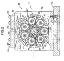
- FIG. 2 is a sectional view along line 2-2 in FIG. 1
- FIG. 3 is an enlarged view of part 3 in FIG. 1
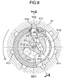
- FIG. 4 is an enlarged sectional view of part 4 in FIG. 1 (sectional view along line 4-4 in FIG. 8)
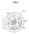
- FIG. 5 is a view from arrowed line 5-5 in FIG. 4
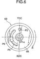
- FIG. 6 is a view from arrowed line 6-6 in FIG. 4
- FIG. 7 is a sectional view along line 7-7 in FIG. 4
- FIG. 8 is a sectional view along line 8-8 in FIG.
- FIG. 9 is a sectional view along line 9-9 in FIG. 4, FIG.
- FIG. 10 is a graph showing torque variations of an output shaft
- FIG. 11 is an explanatory diagram showing the operation of an intake system of a high-pressure stage
- FIG. 12 is an explanatory diagram showing the operation of a discharge system of the high-pressure stage and an intake system of a low-pressure stage
- FIG. 13 is an explanatory diagram showing the operation of a discharge system of the low-pressure stage.
- a rotary fluid machine of the present invention is, for example, an expander M used in a Rankine cycle system, and the thermal energy and the pressure energy of high-temperature, high-pressure steam as a working medium are converted into mechanical energy and output.
- a casing 11 of the expander M is formed from a casing main body 12, a front cover 15 fitted via a seal 13 in a front opening of the casing main body 12 and joined thereto via a plurality of bolts 14, and a rear cover 18 fitted via a seal 16 in a rear opening of the casing main body 12 and joined thereto via a plurality of bolts 17.
- An oil pan 19 abuts against a lower opening of the casing main body 12 via a seal 20 and is joined thereto via a plurality of bolts 21. Furthermore, a breather chamber dividing wall 23 is superimposed on an upper face of the casing main body 12, a breather chamber cover 25 is further superimposed on an upper face of the breather chamber dividing wall 23, and they are together secured to the casing main body 12 by means of a plurality of bolts 26.
- a rotor 27 and an output shaft 28 that can rotate around an axis L extending in the fore-and-aft direction in the center of the casing 11 are united by welding.
- a rear part of the rotor 27 is rotatably supported in the casing main body 12 via an angular ball bearing 29 and a seal 30, and a front part of the output shaft 28 is rotatably supported in the front cover 15 via an angular ball bearing 31 and a seal 32.
- a swash plate holder 36 is fitted via two seals 33 and 34 and a knock pin 35 in a rear face of the front cover 15 and fixed thereto via a plurality of bolts 37, and a swash plate 39 is rotatably supported in the swash plate holder 36 via an angular ball bearing 38.
- the axis of the swash plate 39 is inclined relative to the axis L of the rotor 27 and the output shaft 28, and the angle of inclination is fixed.
- Seven sleeves 41 formed from members that are separate from the rotor 27 are arranged within the rotor 27 so as to surround the axis L at equal intervals in the circumferential direction.
- High-pressure pistons 43 are slidably fitted in high-pressure cylinders 42 formed at inner peripheries of the sleeves 41, which are supported by sleeve support bores 27a of the rotor 27.
- Hemispherical parts of the high-pressure pistons 43 projecting forward from forward end openings of the high-pressure cylinders 42 abut against seven dimples 39a recessed in a rear face of the swash plate 39.
- Heat resistant metal seals 44 are fitted between the rear ends of the sleeves 41 and the sleeve support bores 27a of the rotor 27, and a single set plate 45 retaining the front ends of the sleeves 41 in this state is fixed to a front face of the rotor 27 by means of a plurality of bolts 46.
- the sleeve support bores 27a have a slightly larger diameter in the vicinity of their bases, thus forming a gap ⁇ (see FIG. 3) between themselves and the outer peripheries of the sleeves 41.
- the high-pressure pistons 43 include pressure rings 47 and oil rings 48 for sealing the sliding surfaces with the high-pressure cylinders 42, and the sliding range of the pressure rings 47 and the sliding range of the oil rings 48 are set so as not to overlap each other.
- tapered openings 45a widening toward the front are formed in the set plate 45.
- the sliding range of the pressure rings 47 and the sliding range of the oil rings 48 are set so as not to overlap each other, oil attached to the inner walls of the high-pressure cylinders 42 against which the oil rings 48 slide will not be taken into high-pressure operating chambers 82 due to sliding of the pressure rings 47, thereby reliably preventing the oil from contaminating the steam.
- the high-pressure pistons 43 have a slightly smaller diameter part between the pressure rings 47 and the oil rings 48 (see FIG. 3), thereby preventing effectively the oil attached to the sliding surfaces of the oil rings 48 from moving to the sliding surfaces of the pressure rings 47.
- the high-pressure cylinders 42 are formed by fitting the seven sleeves 41 in the sleeve support bores 27a of the rotor 27, a material having excellent thermal conductivity, heat resistance, abrasion resistance, strength, etc. can be selected for the sleeves 41. This not only improves the performance and the reliability, but also machining becomes easy compared with a case in which the high-pressure cylinders 42 are directly machined in the rotor 27, and the machining precision also increases. When any one of the sleeves 41 is worn or damaged, it is possible to exchange only the sleeve 41 with an abnormality, without exchanging the entire rotor 27, and this is economical.
- the gap ⁇ is formed between the outer periphery of the sleeves 41 and the rotor 27 by slightly enlarging the diameter of the sleeve support bores 27a in the vicinity of the base, even when the rotor 27 is thermally deformed by the high-temperature, high-pressure steam supplied to the high-pressure operating chambers 82, this is prevented from affecting the sleeves 41, thereby preventing the high-pressure cylinders 42 from distorting.
- the seven high-pressure cylinders 42 and the seven high-pressure pistons 43 fitted therein form a first axial piston cylinder group 49.
- Seven low-pressure cylinders 50 are arranged at circumferentially equal intervals on the outer peripheral part of the rotor 27 so as to surround the axis L and the radially outer side of the high-pressure cylinders 42.
- These low-pressure cylinders 50 have a larger diameter than that of the high-pressure cylinders 42, and the pitch at which the low-pressure cylinders 50 are arranged in the circumferential direction is displaced by half a pitch relative to the pitch at which the high-pressure cylinders 42 are arranged in the circumferential direction.
- the seven low-pressure cylinders 50 have low-pressure pistons 51 slidably fitted thereinto, and these low-pressure pistons 51 are connected to the swash plate 39 via links 52. That is, spherical parts 52a at the front end of the links 52 are swingably supported in spherical bearings 54 fixed to the swash plate 39 via nuts 53, and spherical parts 52b at the rear end of the links 52 are swingably supported in spherical bearings 56 fixed to the low-pressure pistons 51 by clips 55.
- a pressure ring 78 and an oil ring 79 are fitted around the outer periphery of each of the low-pressure pistons 51 in the vicinity of the top face thereof so as to adjoin each other. Since the sliding ranges of the pressure ring 78 and the oil ring 79 overlap each other, an oil film is formed on the sliding surface of the pressure ring 78, thus enhancing the sealing characteristics and the lubrication.
- the seven low-pressure cylinders 50 and the seven low-pressure pistons 44 fitted therein form a second axial piston cylinder group 57.
- the front ends of the high-pressure pistons 43 of the first axial piston cylinder group 49 are made in the form of hemispheres and are made to abut against the dimples 39a formed in the swash plate 39, it is unnecessary to connect the high-pressure pistons 43 to the swash plate 39 mechanically, thus reducing the number of parts and improving the ease of assembly.
- the low-pressure pistons 51 of the second axial piston cylinder group 57 are connected to the swash plate 39 via the links 52 and the front and rear spherical bearings 54 and 56, and even when the temperature and the pressure of medium-temperature, medium-pressure steam supplied to the second axial piston cylinder group 57 become insufficient and the pressure of low-pressure operating chambers 84 becomes negative, there is no possibility of the low-pressure pistons 51 becoming detached from the swash plate 39 and causing knocking or damage.
- the rotor 27 and the output shaft 28, which are united, are supported respectively by the angular ball bearing 29 provided on the casing main body 12 and the angular ball bearing 31 provided on the front cover 15, by adjusting the thickness of a shim 58 disposed between the casing main body 12 and the angular ball bearing 29 and the thickness of a shim 59 disposed between the front cover 15 and the angular ball bearing 31, the longitudinal position of the rotor 27 along the axis L can be adjusted.
- the relative positional relationship in the axis L direction between the high-pressure and low-pressure pistons 43 and 51 guided by the swash plate 39, and the high-pressure and low-pressure cylinders 42 and 50 provided in the rotor 27 can be changed, thereby adjusting the expansion ratio of the steam in the high-pressure and low-pressure operating chambers 82 and 84.
- a rotary valve 61 is housed in a circular cross-section recess 27b opening on a rear end face of the rotor 27 and a circular cross-section recess 18a opening on a front face of the rear cover 18.
- the rotary valve 61 which is disposed along the axis L, includes a rotary valve main body 62, a stationary valve plate 63, and a movable valve plate 64.
- the movable valve plate 64 is fixed to the rotor 27 via a knock pin 66 and a bolt 67 while being fitted to the base of the recess 27b of the rotor 27 via a gasket 65.
- the stationary valve plate 63 which abuts against the movable valve plate 64 via flat sliding surfaces 68, is joined via a knock pin 69 to the rotary valve main body 62 so that there is no relative rotation therebetween.
- the movable valve plate 64 and the stationary valve plate 63 therefore rotate relative to each other on the sliding surfaces 68 in a state in which they are in intimate contact with each other.
- the stationary valve plate 63 and the movable valve plate 64 are made of a material having excellent durability, such as a super hard alloy or a ceramic, and the sliding surfaces 68 can be provided with or coated with a member having heat resistance, lubrication, corrosion resistance, and abrasion resistance.
- the rotary valve main body 62 is a stepped cylindrical member having a large diameter part 62a, a medium diameter part 62b, and a small diameter part 62c; an annular sliding member 70 fitted around the outer periphery of the large diameter part 62a is slidably fitted in the recess 27b of the rotor 27 via a cylindrical sliding surface 71, the medium diameter part 62b and the small diameter part 62c are fitted in an inner periphery 18a of the rear cover 18 via seals 72 and 73, and a cylindrical part 62e extending from the small diameter part 62c further extends to the interior of a spring case 94 fixed to a rear face of the rear cover 18 via bolts 93.
- the sliding member 70 is made of a material having excellent durability, such as a super hard alloy or a ceramic.
- a knock pin 74 implanted in the outer periphery of the rotary valve main body 62 engages with a long hole 18b formed in the recess 18a of the rear cover 18 in the axis L direction, and the rotary valve main body 62 is therefore supported so that it can move in the axis L direction but cannot rotate relative to the rear cover 18.
- a plurality of preload springs 75 are supported within the spring case 94 so as to surround the axis L, and a spring seat 95 receiving front ends of these preload springs 75 abuts against a step 62d between the cylindrical part 62e and the small diameter part 62c.
- the rotary valve main body 62 having the step 62d pushed by the preload springs 75 is therefore biased forward so that the sliding surfaces 68 of the stationary valve plate 63 and the movable valve plate 64 are made to come into intimate contact with each other.
- a steam supply pipe 77 having a heat-insulating space 77a in the interior thereof is fixed to the spring case 94 by a nut 96 so as to be positioned on the axis L.
- the steam supply pipe 77 is loosely inserted into the inner periphery 62f of the cylindrical part 62e and the small diameter part 62c of the rotary valve main body 62, and a tapered front end of the steam supply pipe 77 faces an entrance end of a first steam passage P1 across a gap, the first steam passage P1 being formed in the interior of the small diameter part 62c of the rotary valve main body 62.
- a plurality of annular sealing means 97 are disposed between the outer periphery of the steam supply pipe 77 and the inner periphery 62f of the cylindrical part 62e and the small diameter part 62c of the rotary valve main body 62, and the rear end of the annular sealing means 97 is fixed by a retaining member 98 screwed into the inner periphery 62f.
- the sealing means 97 is a gland packing formed from a material having excellent heat resistance such as, for example, an inorganic fiber such as expanded graphite carbon fiber, carbon fiber, or a metal fiber, or an organic fiber such as a fluorine resin fiber or an aramid fiber, and can be elastically deformed easily by an external force, thus allowing relative movement between the rotary valve main body 62 and the steam supply pipe 77.
- a material having excellent heat resistance such as, for example, an inorganic fiber such as expanded graphite carbon fiber, carbon fiber, or a metal fiber, or an organic fiber such as a fluorine resin fiber or an aramid fiber
- the back of the sealing means 97 communicates with an internal space of the spring case 94, and the internal space of the spring case 94 communicates with a steam discharge chamber 90 via a steam recovery passage 18e running through the cover 18.
- FIG. 11 A high-pressure stage steam intake route for supplying high-temperature, high-pressure steam to the first axial piston cylinder group 49 is shown in FIG. 11 by a mesh pattern.
- the first steam passage P1 having its upstream end communicating with a pressure chamber 76, to which the high-temperature, high-pressure steam is supplied from the steam supply pipe 77, runs through the rotary valve main body 62, opens on the surface at which the rotary valve main body 62 is joined to the stationary valve plate 63, and communicates with a second steam passage P2 running through the stationary valve plate 63.
- the joining surface is equipped with a seal 81 (see FIG. 7 and FIG. 11), which seals the outer periphery of a connecting part between the first and second steam passages P1 and P2.
- Seven third steam passages P3 (see FIG. 5) and seven fourth steam passages P4 are formed respectively in the movable valve plate 64 and the rotor 27 at circumferentially equal intervals, and the downstream ends of the fourth steam passages P4 communicate with the seven high-pressure operating chambers 82 defined between the high-pressure cylinders 42 and the high-pressure pistons 43 of the first axial piston cylinder group 49.
- an opening of the second steam passage P2 formed in the stationary valve plate 63 does not open evenly to the front and rear of the top dead center (TDC) of the high-pressure pistons 43, but opens displaced slightly forward in the direction of rotation of the rotor 27, which is shown by the arrow R.
- a high-pressure stage steam discharge route and a low-pressure stage steam intake route for discharging medium-temperature, medium-pressure steam from the first axial piston cylinder group 49 and supplying it to the second axial piston cylinder group 57 are shown in FIG. 12 by a mesh pattern.
- an arc-shaped fifth steam passage P5 opens on a front face of the stationary valve plate 63, and this fifth steam passage P5 communicates with a circular sixth steam passage P6 (see FIG. 7) opening on a rear face of the stationary valve plate 63.
- the fifth steam passage P5 opens from a position displaced slightly forward in the direction of rotation of the rotor 27, which is shown by the arrow R, relative to the bottom dead center (BDC) of the high-pressure pistons 43 to a position displaced slightly backward in the rotational direction relative to the TDC.
- BDC bottom dead center
- a seventh steam passage P7 extending in the axis L direction and an eighth steam passage P8 extending in a substantially radial direction.
- the upstream end of the seventh steam passage P7 communicates with the downstream end of the sixth steam passage P6.
- the downstream end of the eighth steam passage P8 communicates with a tenth steam passage P10 running radially through the sliding member 70 via a ninth steam passage P9 within a coupling member 83 disposed so as to straddle the rotary valve main body 62 and the sliding member 70.
- the tenth steam passage P10 communicates with the seven low-pressure operating chambers 84 defined between the low-pressure cylinders 50 and the low-pressure pistons 41 of the second axial piston cylinder group 57 via seven eleventh steam passages P11 formed radially in the rotor 27.
- the outer periphery of a part where the sixth and seventh steam passages P6 and P7 are connected is sealed by equipping the joining surfaces with a seal 85 (see FIG. 7 and FIG. 12).
- Two seals 86 and 87 are disposed between the inner periphery of the sliding member 70 and the rotary valve main body 62, and a seal 88 is disposed between the outer periphery of the coupling member 83 and the sliding member 70.
- the interiors of the rotor 27 and the output shaft 28 are hollowed out to define a pressure regulating chamber 89, and this pressure regulating chamber 89 communicates with the eighth steam passage P8 via a twelfth steam passage P12 and a thirteenth steam passage P13 formed in the rotary valve main body 62, a fourteenth steam passage P14 formed in the stationary valve plate 63, and a fifteenth steam passage P15 running through the interior of the bolt 67.
- the pressure of the medium-temperature, medium-pressure steam discharged from the seven third steam passages P3 into the fifth steam passage P5 pulsates seven times per revolution of the rotor 27, but since the eighth steam passage P8, which is partway along the supply of the medium-temperature, medium-pressure steam to the second axial piston cylinder group 57, is connected to the pressure regulating chamber 89, the pressure pulsations are damped, steam at a constant pressure is supplied to the second axial piston cylinder group 57, and the efficiency with which the low-pressure operating chambers 84 are charged with the steam can be enhanced.
- the pressure regulating chamber 89 is formed by utilizing dead spaces in the centers of the rotor 27 and the output shaft 28, the dimensions of the expander M are not increased, the hollowing out brings about a weight reduction effect and, moreover, since the cuter periphery of the pressure regulating chamber 89 is surrounded by the first axial piston cylinder group 49, which is operated by the high-temperature, high-pressure steam, there is no resultant heat loss in the medium-temperature, medium-pressure steam supplied to the second axial piston cylinder group 57.
- the rotor 27 can be cooled by the medium-temperature, medium-pressure steam in the pressure regulating chamber 89, and the resulting heated medium-temperature, medium-pressure steam enables the output of the second axial piston cylinder group 57 to be increased.
- FIG. 13 A steam discharge route for discharging the low-temperature, low-pressure steam from the second axial piston cylinder group 57 is shown in FIG. 13 by a mesh pattern.
- an arc-shaped sixteenth steam passage P16 that can communicate with the seven eleventh steam passages P11 formed in the rotor 27 is cut out in the sliding surface 71 of the sliding member 70.
- This sixteenth steam passage P16 communicates with a seventeenth steam passage P17 that is cut out in an arc-shape in the outer periphery of the rotary valve main body 62.
- the sixteenth steam passage P16 opens from a position displaced slightly forward in the direction of rotation of the rotor 27, which is shown by the arrow R, relative to the BDC of the low-pressure pistons 51 to a position displaced rotationally slightly backward relative to the TDC.
- This allows the eleventh steam passages P11 of the rotor 27 to communicate with the sixteenth steam passage P16 of the sliding member 70 over an angular range that starts from the BDC and does not overlap the tenth steam passage P10 (preferably, immediately before overlapping the tenth steam passage P10), and in this range the steam is discharged from the eleventh steam passages P11 to the sixteenth steam passage P16.
- the seventeenth steam passage P17 further communicates with the steam discharge chamber 90 formed between the rotary valve main body 62 and the rear cover 18 via an eighteenth steam passage P18 to a twentieth steam passage P20 formed within the rotary valve main body 62 and a cutout 18d of the rear cover 18, and this steam discharge chamber 90 communicates with a steam discharge hole 18c formed in the rear cover 18.
- the plurality of preload springs 75 apply a preset load to the rotary valve main body 62 and bias it forward in the axis L direction, a surface pressure is generated on the sliding surfaces 68 between the stationary valve plate 63 and the movable valve plate 64, and it is thus possible to prevent effectively the steam from leaking past the sliding surfaces 68. Furthermore, even when the steam supply pipe 77 is moved in the axis L direction due to vibration, etc., the movement is absorbed by the sealing means 97, which is a gland packing, and will not be transmitted to the rotary valve main body 62. It is therefore possible to ensure the intimacy of contact between the sliding surfaces 68 of the stationary valve plate 63 and the movable valve plate 64, thus enabling the supply and discharge of steam to be carried out reliably.
- the sealing means 97 which is a gland packing
- the steam passing through the sealing means 97 is discharged into the steam discharge chamber 90 via the internal space of the spring case 94 and the steam recovery passage 18e.
- recovering the steam that has leaked past the sealing means 97 enables loss of the working medium from the closed circuit of the Rankine cycle system to be prevented, and the necessity for replenishing the working medium can be minimized.
- low temperature, low pressure steam that has leaked past the sealing means 97 is recovered on the downstream side of the first axial piston cylinder group 49 and the second axial piston cylinder group 57, it is possible to prevent the output of the expander M from being decreased by this steam.
- a valve for supplying the medium-temperature, medium-pressure steam to the second axial piston cylinder group 57 is formed on the cylindrical sliding surface 71 on the outer periphery of the rotary valve main body 62, since the pressure of the medium-temperature, medium-pressure steam passing through the valve is lower than the pressure of the high-temperature, high-pressure steam, the leakage of the steam can be suppressed to a practically acceptable level by maintaining a predetermined clearance without generating a surface pressure on the sliding surface 71.
- the first steam passage P1 through which the high-temperature, high-pressure steam passes, the seventh steam passage P7 and the eighth steam passage P8 through which the medium-temperature, medium-pressure steam passes, and the seventeenth steam passage P17 to the twentieth steam passage P20 through which the low-temperature, low-pressure steam passes are collectively formed within the rotary valve main body 62, not only can the steam temperature be prevented from dropping, but also the parts (for example, the seal 81) sealing the high-temperature, high-pressure steam can be cooled by the low-temperature, low-pressure steam, thus improving the durability.
- the rotary valve 61 can be attached to and detached from the casing main body 12 merely by removing the rear cover 18 from the casing main body 12, the ease of maintenance operations such as repair, cleaning, and replacement can be greatly improved. Furthermore, although the temperature of the rotary valve 61 through which the high-temperature, high-pressure steam passes becomes high, since the swash plate 39 and the output shaft 28, where lubrication by oil is required, are disposed on the opposite side to the rotary valve 61 relative to the rotor 27, the oil is prevented from being heated by the heat of the rotary valve 61 when it is at high temperature, which would degrade the performance in lubricating the swash plate 39 and the output shaft 28. Moreover, the oil can exhibit a function of cooling the rotary valve 61, thus preventing overheating.
- high-temperature, high-pressure steam generated by heating water in an evaporator is supplied to the pressure chamber 76 of the expander M via the steam supply pipe 77, and reaches the sliding surface 68 with the movable valve plate 64 via the first steam passage P1 formed in the rotary valve main body 62 of the rotary valve 61 and the second steam passage P2 formed in the stationary valve plate 63 integral with the rotary valve main body 62.
- the second steam passage P2 opening on the sliding surface 68 communicates momentarily with the third steam passage P3 formed in the movable valve plate 64 rotating integrally with the rotor 27, and the high-temperature, high-pressure steam is supplied, via the fourth steam passage P4 formed in the rotor 27, from the third steam passage P3 to, among the seven high-pressure operating chambers 82 of the first axial piston cylinder group 49, the high-pressure operating chamber 82 that is present at the top dead center.
- the high-temperature, high-pressure steam expands within the high-pressure operating chamber 82 and causes the high-pressure piston 43 fitted in the high-pressure cylinder 42 of the sleeve 41 to be pushed forward from top dead center toward bottom dead center, and the front end of the high-pressure piston 43 presses against the dimple 39a of the swash plate 39.
- the reaction force that the high-pressure piston 43 receives from the swash plate 39 gives a rotational torque to the rotor 27.
- the high-temperature, high-pressure steam is supplied into a fresh high-pressure operating chamber 82, thus continuously rotating the rotor 27.
- the medium-temperature, medium-pressure steam pushed out of the high-pressure operating chamber 82 is supplied to the eleventh steam passage P11 communicating with the low-pressure operating chamber 84 that, among the low-pressure operating chambers 84 of the second axial piston cylinder group 57, has reached top dead center accompanying rotation of the rotor 27, via the fourth steam passage P4 of the rotor 27, the third steam passage P3 of the movable valve plate 64, the sliding surface 68, the fifth steam passage P5 and the sixth steam passage P6 of the stationary valve plate 63, the seventh steam passage P7 to the tenth steam passage P10 of the rotary valve main body 62, and the sliding surface 71.
- the low-pressure piston 51 fitted in the low-pressure cylinder 50 is pushed forward from top dead center toward bottom dead center, and the link 52 connected to the low-pressure piston 51 presses against the swash plate 39.
- the pressure force of the low-pressure piston 51 is converted into a rotational force of the swash plate 39 via the link 52, and this rotational force transmits a rotational torque from the high-pressure piston 43 to the rotor 27 via the dimple 39a of the swash plate 39.
- the rotational torque is transmitted to the rotor 27, which rotates synchronously with the swash plate 39.
- the link 52 carries out the function of maintaining a connection between the low-pressure piston 51 and the swash plate 39, and it is arranged that the rotational torque due to the expansion is transmitted from the high-pressure piston 43 to the rotor 27 rotating synchronously with the swash plate 39 via the dimples 39a of the swash plate 39 as described above.
- the medium-temperature, medium-pressure steam is supplied into a fresh low-pressure operating chamber 84, thus continuously rotating the rotor 27.
- the pressure of the medium-temperature, medium-pressure steam discharged from the high-pressure operating chambers 82 of the first axial piston cylinder group 49 pulsates seven times for each revolution of the rotor 27, but by damping these pulsations by the pressure regulating chamber 89 steam at a constant pressure can be supplied to the second axial piston cylinder group 57, thereby enhancing the efficiency with which the low-pressure operating chambers 84 are charged with the steam.
- the outputs of the first and second axial piston cylinder groups 49 and 57 can be combined to drive the output shaft 28, thereby achieving a high output while reducing the dimensions of the expander M.
- the seven high-pressure pistons 43 of the first axial piston cylinder group 49 and the seven high-pressure pistons 51 of the second axial piston cylinder group 57 are displaced by half a pitch in the circumferential direction, as shown in FIG. 10, pulsations in the output torque of the first axial piston cylinder group 49 and pulsations in the output torque of the second axial piston cylinder group 57 are counterbalanced, thus making the output torque of the output shaft 28 flat.
- axial type rotary fluid machines characteristically have a high space efficiency compared with radial type rotary fluid machines
- the space efficiency can be further enhanced.
- the cylinders of the first axial piston cylinder group 49 which are required to have only a small diameter because they are operated by high-pressure steam having a small volume, are arranged on the radially inner side
- the cylinders of the second axial piston cylinder group 57 which are required to have a large diameter because they are operated by low-pressure steam having a large volume, are arranged on the radially outer side
- the space can be utilized effectively, thus making the expander M still smaller.
- the cylinders 42 and 50 and the pistons 43 and 51 that are used have circular cross sections, which enables machining to be carried out with high precision, the amount of steam leakage can be reduced in comparison with a case in which vanes are used, and a yet higher output can thus be anticipated.
- the first axial piston cylinder group 49 which is operated by high-temperature steam
- the second axial piston cylinder group 57 which is operated by low-temperature steam
- the difference in temperature between the second axial piston cylinder group 57 and the outside of the casing 11 can be minimized, the amount of heat released outside the casing 11 can be minimized, and the efficiency of the expander M can be enhanced.
- the heat escaping from the high-temperature first axial piston cylinder group 49 on the radially inner side can be recovered by the low-temperature second axial piston cylinder group 57 on the radially outer side, the efficiency of the expander M can be further enhanced.
- the sliding surfaces 68 on the high-pressure side is present deeper within the recess 27b of the rotor 27 than the sliding surfaces 71 on the low-pressure side, the difference in pressure between the outside of the casing 11 and the sliding surfaces 71 on the low-pressure side can be minimized, the amount of leakage of steam past the sliding surfaces 71 on the low-pressure side can be reduced and, moreover, the pressure of steam leaking past the sliding surfaces 68 on the high-pressure side can be recovered by the sliding surfaces 71 on the low-pressure side and utilized effectively.
- the operating part of the present invention is not limited to the axial piston cylinder groups of the embodiment, and a radial piston cylinder type or a vane type may be employed.
- the rotary fluid machine of the present invention can be applied suitably to an expander that employs steam as a working medium, but it can also be applied to a compressor that compresses a compressible fluid such as air or a pump that feeds by pressure an incompressible fluid such as oil or water.
Landscapes
- Engineering & Computer Science (AREA)
- Mechanical Engineering (AREA)
- General Engineering & Computer Science (AREA)
- Compressors, Vaccum Pumps And Other Relevant Systems (AREA)
Abstract
Description
Claims (4)
- A rotary fluid machine comprising:wherein a working medium supply pipe (77) is provided separately from the rotary valve (61), the working medium supply pipe being positioned on the axis (L) of the rotor (27) and supplying the working medium to the rotary valve (61), and sealing means (97) is disposed between the working medium supply pipe (77) and the rotary valve (61), the sealing means (97) having the function of preventing movement of the working medium supply pipe (77) in the axial (L) direction of the rotor (27) from being transmitted to the rotary valve (61).a casing (11);a rotor (27) rotatably supported in the casing (11);an operating part (49, 57) provided in the rotor (27); anda rotary valve (61) that is provided between the casing (11) and the rotor (27) and controls the intake and discharge of a working medium to and from the operating part (49, 57) via sliding surfaces (68) that are perpendicular to the axis (L) of the rotor (27);
- The rotary fluid machine according to Claim 1, wherein the sealing means (97) is a gland packing.
- The rotary fluid machine according to Claim 2, wherein the rotary fluid machine further comprises working medium recovery means (94, 18e) for recovering working medium that has leaked past the sealing means (97).
- The rotary fluid machine according to Claim 3, wherein the working medium recovery means (94, 18e) returns the recovered working medium to a downstream side of the operating part (49, 57).
Applications Claiming Priority (3)
| Application Number | Priority Date | Filing Date | Title |
|---|---|---|---|
| JP2002011015 | 2002-01-21 | ||
| JP2002011015A JP2003214101A (en) | 2002-01-21 | 2002-01-21 | Rotary fluid machinery |
| PCT/JP2003/000332 WO2003062603A1 (en) | 2002-01-21 | 2003-01-17 | Rotary type fluid machine |
Publications (2)
| Publication Number | Publication Date |
|---|---|
| EP1469162A1 true EP1469162A1 (en) | 2004-10-20 |
| EP1469162A4 EP1469162A4 (en) | 2005-02-02 |
Family
ID=27606004
Family Applications (1)
| Application Number | Title | Priority Date | Filing Date |
|---|---|---|---|
| EP03701753A Withdrawn EP1469162A4 (en) | 2002-01-21 | 2003-01-17 | Rotary type fluid machine |
Country Status (4)
| Country | Link |
|---|---|
| US (1) | US20050220643A1 (en) |
| EP (1) | EP1469162A4 (en) |
| JP (1) | JP2003214101A (en) |
| WO (1) | WO2003062603A1 (en) |
Cited By (2)
| Publication number | Priority date | Publication date | Assignee | Title |
|---|---|---|---|---|
| WO2012168083A3 (en) * | 2011-06-09 | 2013-08-15 | Robert Bosch Gmbh | Axial piston machine of swash-plate design |
| CN107208616A (en) * | 2015-01-23 | 2017-09-26 | 杜尔系统股份公司 | Pump group part and corresponding operation method |
Families Citing this family (4)
| Publication number | Priority date | Publication date | Assignee | Title |
|---|---|---|---|---|
| US7799221B1 (en) * | 2008-01-15 | 2010-09-21 | Macharg John P | Combined axial piston liquid pump and energy recovery pressure exchanger |
| KR20110100472A (en) * | 2010-03-04 | 2011-09-14 | 효성굿스프링스 주식회사 | Energy recovery device of seawater desalination system |
| US20170184097A1 (en) | 2015-12-29 | 2017-06-29 | Ge Oil & Gas Esp, Inc. | Linear Hydraulic Pump for Submersible Applications |
| US20170184089A1 (en) * | 2015-12-29 | 2017-06-29 | Ge Oil & Gas Esp, Inc. | Rotary Hydraulic Pump with ESP Motor |
Family Cites Families (9)
| Publication number | Priority date | Publication date | Assignee | Title |
|---|---|---|---|---|
| JPS4898632A (en) * | 1972-03-27 | 1973-12-14 | ||
| IT1082968B (en) * | 1977-04-05 | 1985-05-21 | Gherner Lidio | HYDRAULIC AXIAL PISTON MOTOR |
| JPS61155610U (en) * | 1985-03-15 | 1986-09-26 | ||
| CA1268687A (en) * | 1986-01-20 | 1990-05-08 | Tsutomu Hayashi | Swash plate type hydraulic system |
| JPS6371501A (en) * | 1986-09-12 | 1988-03-31 | Ckd Corp | Axial type air motor |
| US4794756A (en) * | 1987-12-18 | 1989-01-03 | Sundstrand Corporation | Hydraulic differential |
| JPH02252978A (en) * | 1989-03-24 | 1990-10-11 | Nippondenso Co Ltd | Axial piston motor |
| US5975864A (en) * | 1998-02-19 | 1999-11-02 | Jetech, Inc. | Pump with self-reciprocating pistons |
| JP3924999B2 (en) * | 1999-08-12 | 2007-06-06 | 株式会社日立製作所 | Fuel pump and in-cylinder injection engine using the same |
-
2002
- 2002-01-21 JP JP2002011015A patent/JP2003214101A/en not_active Withdrawn
-
2003
- 2003-01-17 US US10/500,691 patent/US20050220643A1/en not_active Abandoned
- 2003-01-17 EP EP03701753A patent/EP1469162A4/en not_active Withdrawn
- 2003-01-17 WO PCT/JP2003/000332 patent/WO2003062603A1/en not_active Ceased
Cited By (3)
| Publication number | Priority date | Publication date | Assignee | Title |
|---|---|---|---|---|
| WO2012168083A3 (en) * | 2011-06-09 | 2013-08-15 | Robert Bosch Gmbh | Axial piston machine of swash-plate design |
| CN107208616A (en) * | 2015-01-23 | 2017-09-26 | 杜尔系统股份公司 | Pump group part and corresponding operation method |
| US10975858B2 (en) | 2015-01-23 | 2021-04-13 | Dürr Systems Ag | Pump arrangement and corresponding operating method |
Also Published As
| Publication number | Publication date |
|---|---|
| WO2003062603A1 (en) | 2003-07-31 |
| EP1469162A4 (en) | 2005-02-02 |
| US20050220643A1 (en) | 2005-10-06 |
| JP2003214101A (en) | 2003-07-30 |
Similar Documents
| Publication | Publication Date | Title |
|---|---|---|
| EP1367218B1 (en) | Expansion machine | |
| EP1367219B1 (en) | Rotary hydraulic machine | |
| EP1469162A1 (en) | Rotary type fluid machine | |
| US6846163B2 (en) | Rotary fluid machine having rotor segments on the outer periphery of a rotor core | |
| EP1367220B1 (en) | Rotary hydraulic machine | |
| US20050147507A1 (en) | Expander | |
| US20060153698A1 (en) | Rotary fluid machine | |
| US20050254965A1 (en) | Expansion machine | |
| US20040216602A1 (en) | Rotating fluid machine | |
| US20040216601A1 (en) | Rotating fluid machine | |
| US20050089410A1 (en) | Rotating fluid machine | |
| US20050132703A1 (en) | Rotating fluid machine | |
| JP4104351B2 (en) | Expansion machine | |
| US20050158181A1 (en) | Expansion engine | |
| US20050169771A1 (en) | Rotating fluid machine | |
| JP2003232202A (en) | Rotary fluid machine | |
| JP2004270524A (en) | Rotary fluid machinery | |
| JP2004239066A (en) | Rotary fluid machinery | |
| JP2003232201A (en) | Rotary fluid machine | |
| JP2004204766A (en) | Rotary fluid machinery | |
| JP2003239703A (en) | Rotary fluid machine |
Legal Events
| Date | Code | Title | Description |
|---|---|---|---|
| PUAI | Public reference made under article 153(3) epc to a published international application that has entered the european phase |
Free format text: ORIGINAL CODE: 0009012 |
|
| 17P | Request for examination filed |
Effective date: 20040622 |
|
| AK | Designated contracting states |
Kind code of ref document: A1 Designated state(s): AT BE BG CH CY CZ DE DK EE ES FI FR GB GR HU IE IT LI LU MC NL PT SE SI SK TR |
|
| A4 | Supplementary search report drawn up and despatched |
Effective date: 20041221 |
|
| RIC1 | Information provided on ipc code assigned before grant |
Ipc: 7F 01B 3/00 B Ipc: 7F 01B 3/02 B Ipc: 7F 01B 31/30 A |
|
| 17Q | First examination report despatched |
Effective date: 20050228 |
|
| STAA | Information on the status of an ep patent application or granted ep patent |
Free format text: STATUS: THE APPLICATION IS DEEMED TO BE WITHDRAWN |
|
| 18D | Application deemed to be withdrawn |
Effective date: 20050712 |