BACKGROUND OF THE INVENTION
Field of the Invention:
The present invention relates to a novel polymer,
a polymer suitably used in forming an organic
electroluminescence device, a polymer composition for
organic electroluminescence devices and an organic
electroluminescence device.
Description of the Background Art:
An organic electroluminescence device (hereinafter
also referred to as "organic EL device") is expected as a
display element of the coming generation because it has
such excellent properties as can be driven by DC voltage,
is wide in angle of visibility and high in visibility
owing to its self-luminescent nature, and is fast in the
speed of response, and researches thereof are being
actively conducted.
As such organic EL devices, there have heretofore
been known those of a single-layer structure that a
luminescent layer composed of an organic material is
formed between an anode and a cathode, and those of
multi-layer structures such as a structure having a hole
transport layer between an anode and a luminescent layer
and a structure having an electron transport layer
between a cathode and a luminescent layer. In all of
these organic EL devices, light is emitted by recombining
an electron injected from the cathode with a hole
injected from the anode in the luminescent layer.
As processes for forming functional organic layers
such as the luminescent layer and the charge transport
layers for transporting a charge such as an electron or
hole in such an organic EL device, there have been known
a dry method that an organic material layer is formed by
vacuum deposition and a wet method that a solution with
an organic material dissolved therein is applied and
dried to form a layer. Among these, the dry method is
difficult to meet mass production because the process is
complicated, and there is a limit to the formation of a
large-area layer. On the contrary, the wet method can
meet mass production because the process is relatively
simple. For example, a large-area functional organic
layer can be easily formed according to an ink-jet method.
In these respects, the wet method is useful compared with
the dry method.
On the other hand, the functional organic layer
making up the luminescent layer of the organic EL device
is required to achieve high luminous luminance. In order
to realize high luminous luminance, it has been recently
attempted to utilize energy of a molecule in a triplet
state that is an excitation state, or the like for light
emission of an organic EL device. Specifically, it has
been reported to achieve an external quantum efficiency
of 8% exceeding 5% that has heretofore been considered to
be a critical value of the external quantum efficiency in
an organic EL device according to an organic EL device
having such construction (see for example, "Applied
Physics Letters", Vol. 75, p. 4, 1999).
Since this organic EL device is formed with a low-molecular
weight material by the dry method, for example,
a vapor deposition method or the like, however, it
involves a problem that its physical durability and
thermal durability are low.
As the organic EL device utilizing energy of the
molecule in the triplet state or the like, there has been
proposed that obtained by forming a luminescent layer
with a composition composed of, for example, an iridium
metal complex, polyvinylcarbazole and oxadiazole by the
wet method (see Japanese Patent Application Laid-Open No.
2001-257076).
In this organic EL device, the luminescent layer
contains low-molecular weight oxadiazole. This low-molecular
weight oxadiazole is low in stability to Joule
heat generated during continuous driving. Accordingly,
this organic EL device involves a problem that stable
light emission cannot be achieved during continuous
driving.
SUMMARY OF THE INVENTION
The present invention has been made on the basis of
the foregoing circumstances and has as its object the
provision of a novel polymer suitable for a forming
material of, for example, an organic electroluminescence
device, and a polymer for forming an organic
electroluminescence device and a polymer composition for
organic electroluminescence devices, by which a thin film
can be formed with ease by the wet method, and an organic
electroluminescence device that can achieve light
emission high in luminous luminance and stable even
during continuous driving can be provided.
Another object of the present invention is to
provide an organic electroluminescence device that can
achieve light emission high in luminous luminance and
stable even during continuous driving.
According to the present invention, there is thus
provided a polymer for forming an organic
electroluminescence device, which is composed of a
polymer having, in its main chain, a structural unit
represented by the following general formula (1-a) and a
structural unit represented by the following general
formula (1-b):
wherein R
1 is an alkyl group or, an aromatic group which
may be substituted, R
2 and R
3 are, independently of each
other, a monovalent organic group and may be the same or
different from each other, m is an integer of 0 to 3, and
n is an integer of 0 to 3; and
wherein R
4 is an alkyl group, R
5 and R
6 are, independently
of each other, a monovalent organic group and may be the
same or different from each other, p is an integer of 0
to 3, and q is an integer of 0 to 3, and;
the polymer being used for forming an electroluminescence
device.
The polymer according to the present invention for
forming an organic electroluminescence device may
comprise a structural unit represented by the following
general formula (a):
wherein R
1 is an alkyl group or, an aromatic group which
may be substituted, R
2 and R
3 are, independently of each
other, a monovalent organic group and may be the same or
different from each other, R
4 is an alkyl group, R
5 and R
6
are, independently of each other, a monovalent organic
group and may be the same or different from each other, m
is an integer of 0 to 3, n is an integer of 0 to 3, p is
an integer of 0 to 3, q is an integer of 0 to 3, and a
and b are the numbers of repeated structural units.
The polymer according to the present invention for
forming an organic electroluminescence device may also
comprise a structural unit represented by the following
general formula (b):
wherein R
1 is an alkyl group or, an aromatic group which
may be substituted, R
2 and R
3 are, independently of each
other, a monovalent organic group and may be the same or
different from each other, R
4 is an alkyl group, R
5 and R
6
are, independently of each other, a monovalent organic
group and may be the same or different from each other, m
is an integer of 0 to 3, n is an integer of 0 to 3, p is
an integer of 0 to 3, and q is an integer of 0 to 3.
The polymer according to the present invention for
forming an organic electroluminescence device may have a
weight average molecular weight of 5,000 to 1,000,000 in
terms of polystyrene as measured by gel permeation
chromatography.
According to the present invention, there is also
provided a polymer composition for organic
electroluminescence devices, comprising a polymer
component composed of the above-described polymer for
forming an organic electroluminescence device, and a
complex component composed of an iridium complex compound
that is a triplet luminescent material.
According to the present invention, there is
further provided an organic electroluminescence device
comprising a functional organic layer having a function
as a luminescent layer or charge transport layer formed
by the above-described polymer composition for organic
electroluminescence devices.
According to the present invention, there is
provided a polymer having, in its main chain, a
structural unit represented by the following general
formula (2-a) and a structural unit represented by the
following general formula (2-b):
wherein R
7 is an alkyl group or, an aromatic group which
may be substituted, R
8 and R
9 are, independently of each
other, a monovalent organic group and may be the same or
different from each other, r is an integer of 0 to 3, and
s is an integer of 0 to 3; and
wherein R
10 and R
11 are, independently of each other, a
monovalent organic group and may be the same or different
from each other, R
12 and R
13 are, independently of each
other, a monovalent organic group and may be the same or
different from each other, t is an integer of 0 to 3, u
is an integer of 0 to 3, v is an integer of 0 to 4, and w
is an integer of 0 to 4.
According to the present invention, there is also
provided a polymer for forming an organic
electroluminescence device, which is composed of the
polymer described above and is used for forming an
electroluminescence device.
The polymer according to the present invention for
forming an organic electroluminescence device may
comprise a structural unit represented by the following
general formula (c):
wherein R
7 is an alkyl group or, an aromatic group which
may be substituted, R
8 and R
9 are, independently of each
other, a monovalent organic group and may be the same or
different from each other, R
10 and R
11 are, independently
of each other, a monovalent organic group and may be the
same or different from each other, R
12 and R
13 are,
independently of each other, a monovalent organic group
and may be the same or different from each other, r is an
integer of 0 to 3, s is an integer of 0 to 3, t is an
integer of 0 to 3, u is an integer of 0 to 3, v is an
integer of 0 to 4, w is an integer of 0 to 4, and c and d
are the numbers of repeated structural units.
In the polymer described above, a ratio (d/c) of
the numbers c and d of repeated structural units in the
general formula (c) may preferably be 1 to 5.
In the polymer for forming an organic
electroluminescence device, the polymer may preferably be
obtained by subjecting a monomer having 2 functional
groups selected from reactive halide functional groups
and boron derivative functional groups and a skeletal
structure derived from carbazole, and a monomer having 2
functional groups selected from reactive halide
functional groups and boron derivative functional groups
and a skeletal structure derived from spirofluorene to a
coupling reaction in the presence of a palladium catalyst.
The polymer according to the present invention for
forming an organic electroluminescence device may have a
weight average molecular weight of 5,000 to 1,000,000 in
terms of polystyrene as measured by gel permeation
chromatography.
According to the present invention, there is
further provided a polymer composition for organic
electroluminescence devices, comprising a polymer
component composed of the above-described polymer for
forming an organic electroluminescence device, and a
complex component composed of an iridium complex compound
that is a triplet luminescent material.
According to the present invention, there is still
further provided an organic electroluminescence device
comprising a functional organic layer having a function
as a luminescent layer or charge transport layer formed
by the above-described polymer for forming an organic
electroluminescence device.
According to the present invention, there is yet
still further provided an organic electroluminescence
device comprising a functional organic layer having a
function as a luminescent layer or charge transport layer
formed by the above-described polymer composition for
organic electroluminescence devices.
The organic electroluminescence devices may
preferably have a hole blocking layer.
According to the present invention, polymers
suitably used in forming organic electroluminescence
devices are provided.
According to the polymers of the present invention
for forming organic electroluminescence devices, thin
film-like organic electroluminescence devices that can
achieve light emission high in luminous luminance and
stable even during continuous driving can be formed with
ease by the wet method because the polymers are each
composed of a specific conjugated polymer having the
specific structural unit(s).
A polymer component composed of the polymer for
forming an organic electroluminescence device is combined
with a complex component composed of an iridium complex
compound that is a triplet luminescent material, whereby
a polymer composition for organic electroluminescence
devices, by which a thin film can be formed with ease by
the wet method, can be provided. According to such a
polymer composition, an organic electroluminescence
device that can achieve light emission high in luminous
luminance and stable even during continuous driving can
be provided.
According to the organic electroluminescence
devices of the present invention, light emission high in
luminous luminance and stable even during continuous
driving can be achieved.
BRIEF DESCRIPTION OF THE DRAWING
The above and other objects, features and
advantages of the present invention will become apparent
from the following description and the appended claims,
taken in conjunction with the accompanying drawings, in
which:
DETAILED DESCRIPTION OF THE PREFERRED EMBODIMENTS
The embodiments of the present invention will
hereinafter be described in details.
<Polymer for Forming Organic EL Device>
As the polymers according to the present invention
for forming an organic EL device, are proposed a
conjugated polymer (hereinafter also referred to as
"first conjugated polymer") having a structural unit
(hereinafter also referred to as "carbazole structural
unit (1)") represented by the general formula (1-a) and a
structural unit (hereinafter also referred to as
"fluorene structural unit") represented by the general
formula (1-b) in its main chain, and a conjugated polymer
(hereinafter also referred to as "second conjugated
polymer") having a structural unit (hereinafter also
referred to as "carbazole structural unit (2)")
represented by the general formula (2-a) and a structural
unit (hereinafter also referred to as "spirofluorene
structural unit") represented by the general formula
(2-b) in its main chain, which are both used for forming
an organic EL device.
[First Conjugated Polymer]
The first conjugated polymer making up the polymer
according to the present invention for forming an organic
EL device is composed of a conjugated polymer having the
carbazole structural unit (1) and the fluorene structural
unit in its main chain.
The first conjugated polymer may be any of a random
copolymer, block copolymer and alternating copolymer of
the carbazole structural unit (1) and the fluorene
structural unit.
In the general formula (1-a) representing the
carbazole structural unit (1), R1 is an alkyl group or,
an aromatic group which may be substituted, and is
particularly preferably an ethyl group.
R2 and R3 are, independently of each other, a
monovalent organic group and may be the same or different
from each other. However, they may preferably be the
same.
Examples of the monovalent organic group in each of
R2 and R3 include methyl, ethyl, propyl, isopropyl and
phenyl groups.
m and n are, independently of each other, an
integer of 0 to 3 and may be particularly preferably both
0. The fact that m and n are 0 means no substituent
group is bonded, but a hydrogen atom is bonded.
As a specific preferable example of the carbazole
structural unit (1), may be mentioned a structural unit
in which R1 is an ethyl group, and both m and n are 0.
In the general formula (1-b) representing the
fluorene structural unit, R4 is an alkyl group and is
particularly preferably a hexyl or octyl group.
R5 and R6 are, independently of each other, a
monovalent organic group and may be the same or different
from each other. However, they may preferably be the
same.
Examples of the monovalent organic group in each of
R5 and R6 include alkyl groups having 1 to 22 carbon
atoms, heteroaryl groups having 2 to 20 carbon atoms,
aryl groups having 6 to 20 carbon atoms, alkoxyl groups
having 1 to 20 carbon atoms, a nitrile group and aromatic
amino groups. Among these, t-butyl, diphenylamino, tolyl,
methoxy and cyano groups are particularly preferred.
p and q are, independently of each other, an
integer of 0 to 3 and may be particularly preferably both
0. The fact that m and n are 0 means no substituent
group is bonded, but a hydrogen atom is bonded.
As a specific preferable example of the fluorene
structural unit, may be mentioned a structural unit in
which R4 is a hexyl or octyl group, and both p and q are
0.
As specific preferable examples of the first
conjugated polymer, may be mentioned those respectively
containing the structural units represented by the
general formulae (a) and (b). When the first conjugated
polymer is a polymer containing the structural unit
represented by the general formula (a), the ratio a:b of
the repeated number a of carbazole structural units to
the repeated number b of fluorene structural units is
preferably 2:8 to 8:2 though not particularly limited.
The first conjugated polymer preferably has a
weight average molecular weight of 5,000 to 1,000,000,
particularly 10,000 to 500,000 in terms of polystyrene as
measured by gel permeation chromatography. If the weight
average molecular weight is lower than 5,000, such a
polymer and the resulting polymer composition have a
possibility that heat resistance and, stability and
mechanical strength in a state of a thin film may be
insufficient. If the weight average molecular weight
exceeds 1,000,000 on the other hand, the resulting
polymer composition tends to be markedly high in its
solution viscosity, and so the handling property thereof
may possibly be lowered in the production of organic EL
devices. It is hence not preferable to use a polymer
having such too low or high molecular weight.
The molecular weight distribution of the first
conjugated polymer is preferably at most 5.
Such a first conjugated polymer can be formed in
accordance with, for example, the method (hereinafter
referred to as "Suzuki's method") disclosed in
Organometallics 3, 1261 (1984), the method (hereinafter
referred to as "Yamamoto's method") disclosed in Progress
in Polymer Science Vol. 17, 1153 (1992), or the like.
The first conjugated polymer formed by the Suzuki's
method becomes an alternating copolymer containing the
structural unit represented by the general formula (b),
while the first conjugated polymer formed by the
Yamamoto's method becomes a random copolymer containing
the structural unit represented by the general formula
(a).
According to the Suzuki's method, the first
conjugated polymer is formed by reacting a monomer
(hereinafter referred to as "carbazole skeletal monomer")
having 2 specific functional groups and a skeletal
structure derived from carbazole and a monomer
(hereinafter referred to as "fluorene skeletal monomer")
having 2 specific functional groups and a skeletal
structure derived from fluorene in the presence of a
basic compound and a palladium catalyst in a reaction
solvent.
In this specification, the term "specific
functional groups" indicate reactive halide functional
groups and boron derivative functional groups.
Combinations of the carbazole skeletal monomer and
fluorene skeletal monomer used in the Suzuki's method
include the following 3 combinations:
In the carbazole skeletal monomer, the 2 specific
functional groups are preferably bonded to carbon atoms
located at positions 3 and 6, respectively.
In the fluorene skeletal monomer, the 2 specific
functional groups are preferably bonded to carbon atoms
located at positions 2 and 7, respectively.
Examples of the reactive halide functional groups
include a -Cl group, a -Br group, an -I group, groups
derived from triflate (CF3SO3 -), groups derived from
tosylate and groups derived from mesylate.
Among these, the -Br and -I groups are preferred.
Examples of the boron derivative functional groups
include a boric group represented by the formula -B(OH)2,
borate groups and borane groups.
As the borate groups, are preferred groups
represented by the formula -B (OR14) (OR15) and groups
represented by the formula -B(OR16O).
As the borane groups, are preferred groups
represented by the formula -BR17R18.
R14 in the borate groups is an alkyl group which
has 1 to 6 carbon atoms and may be substituted.
R15 is a hydrogen atom or an alkyl group which has
1 to 6 carbon atoms and may be substituted.
R16 is such a divalent hydrocarbon group that
(OR 16O) in the formula becomes a 5-membered or 6-membered
ester ring. Specifically, it is preferably an alkylene
group having 2 or 3 carbon atoms, an o-phenylene group or
a m-phenylene group. These alkylene groups and phenylene
groups may be substituted.
Examples of preferable groups as the borate groups
of such a structure include groups derived from products
by esterification of an alcohol having 1 to 6 carbon
atoms, an ethanediol such as pinacol, propanediol, or an
ortharomatic diol such as 1,2-dihydroxybenzene with its
corresponding boric acid.
R17 and R18 in the borane groups are, independently
of each other, an alkyl group which has 1 to 6 carbon
atoms and may be substituted. These groups may or may
not form a ring together.
As specific preferable examples of the carbazole
skeletal monomer and fluorene skeletal monomer used in
the Suzuki's method, may be mentioned a compound
represented by the following formula (A) for the
carbazole skeletal monomer and a compound represented by
the following formula (B) for the fluorene skeletal
monomer.
Water, an inert organic solvent or a mixture of
water and an inert organic solvent may be used as the
reaction solvent. Among these, the mixture of water and
the inert organic solvent is preferably used.
Examples of the inert organic solvent include
ethers such as dimethoxyethane, diethylene glycol
dimethyl ether, tetrahydrofuran, dioxane, diisopropyl
ether and tert-butyl methyl ether; hydrocarbons such as
hexane, heptane, cyclohexane, toluene and xylene;
alcohols such as methanol, ethanol, 1-propanol, 2-propanol,
1-butyl alcohol, tert-butyl alcohol and
ethylene glycol; ketones such as ethyl methyl ketone and
isobutyl methyl ketone; amides such as dimethylformamide,
dimethylacetamide and N-methylpyrrolidone; and mixtures
thereof. These inert organic solvents may be used either
singly or in any combination thereof.
Among these, dimethoxyethane, tetrahydrofuran,
cyclohexane, toluene, xylene, ethanol, 1-propanol, 2-propanol,
1-butyl alcohol, tert-butyl alcohol and
mixtures thereof are preferably used.
Specific preferable examples of the reaction
solvent include a mixture of water and toluene, a mixture
of water, toluene and tetrahydrofuran and a mixture of
water, toluene and ethanol.
The amount of the reaction solvent used varies
according to the kinds of the monomers used in the
reaction, but is generally a proportion that the total
concentration of the monomers used in the reaction
amounts to 9 to 30 % by mass.
As the basic compound, may be used, for example, an
alkali metal hydroxide, alkaline earth metal hydroxide,
alkali metal carbonate, alkaline earth metal carbonate,
alkali metal acetate, alkaline earth metal acetate,
alkali metal hydrogencarbonate, alkaline earth metal
hydrogencarbonate, alkali metal alkoxide, alkaline earth
metal alkoxide, primary amine, secondary amine or
tertiary amine.
Among these, alkali metal hydroxides such as sodium
hydroxide and potassium hydroxide, alkali metal
carbonates such as lithium carbonate, sodium carbonate
and potassium carbonate, and alkali metal
hydrogencarbonates are preferably used.
The amount of the basic compound used is preferably
100 to 500 mol%, particularly preferably 150 to 400 mol%,
most preferably 180 to 250 mol% based on the total moles
of the boron derivative functional groups in the monomers
used in the reaction.
As the palladium catalyst, may be used a
palladium(0) complex or palladium(II) salt. However, the
palladium(0) complex is preferably used.
Among these, tetrakis(triphenylphosphine)palladium
(Pd(PPh3)4) is preferably used.
The amount of the palladium catalyst used is 0.01
to 5 mol%, preferably 0.05 to 3 mol%, particularly
preferably 0.1 to 1.5 mol% based on the total moles of
the monomers used in the reaction.
The reaction temperature is 0 to 200°C, preferably
30 to 170°C, particularly preferably 50 to 150°C, most
preferably 60 to 120°C.
The reaction time is 1 to 200 hours, preferably 5
to 150 hours, particularly preferably 24 to 100 hours.
According to the Yamamoto's method on the other
hand, the first conjugated polymer is formed by
subjecting a monomer compound (hereinafter referred to as
"halogenated fluorene compound") having 2 reactive halide
functional groups and a skeletal structure derived from
fluorene and a monomer compound (hereinafter referred to
as "halogenated carbazole compound") having 2 reactive
halide functional groups and a skeletal structure derived
from carbazole to a coupling reaction in the presence of
a nickel catalyst.
As examples of the reactive halide functional
groups, may be mentioned -Br, -Cl and -I groups. Among
these, the -Br group is preferably used.
Examples of the halogenated carbazole compound
include compounds that the hydrogen atom bonded to the
nitrogen atom of carbazole is substituted by an alkyl
group having 1 to 22 carbon atoms or an aromatic group
having 1 to 3 ring(s) (for example, phenyl, naphthyl,
anthryl or xylylene group) which may be substituted.
Among these, N-ethyldibromocarbazole and N-phenylbromocarbazole
are preferred.
As examples of the halogenated fluorene compound,
may be mentioned di(2-ethylhexyl)dibromofluorene,
dihexyldibromofluorene, dioctyldibromofluorene and
di(methoxycarbonylethyl)dibromofluorene.
Among these, dihexyldibromofluorene and
dioctyldibromofluorene are preferred.
Examples of the nickel catalyst include nickel of 0
valence, bis(1,5-cyclooctadienyl)nickel(0), tetrakis-(triphenylphosphite)
nickel (0) and tetrakis(triphenylphosphine)nickel(0).
Bis(1,5-cyclooctadienyl)nickel(0)
is particularly preferably used.
The amount of the nickel catalyst used is 50 to 500
mol%, preferably 70 to 400 mol%, particularly preferably
100 to 200 mol% based on the total moles of the monomers
used in the reaction.
The reaction temperature is 50 to 120°C, preferably
60 to 100°C, particularly preferably 70 to 90°C.
The reaction time is 1 to 100 hours, preferably 3
to 80 hours, particularly preferably 6 to 70 hours.
The reaction product obtained by the polymerization
process according to each of the Suzuki's method and
Yamamoto's method is preferably subjected to a post
treatment that a low-molecular weight component is
removed by, for example, preparative gel permeation
chromatography. An organic EL device still higher in
luminous efficiency can be provided by conducting such a
post treatment.
The polymer for forming an organic EL device
composed of such a first conjugated polymer as described
above is used in formation of an organic EL device as a
material for forming a functional organic layer such as a
luminescent layer or charge transport layer by using it
singly or together with, for example, a luminescent
material having phosphorescent property.
[Second Conjugated Polymer]
The second conjugated polymer making up the polymer
according to the present invention for forming an organic
EL device is composed of a conjugated polymer having the
carbazole structural unit (2) and the spirofluorene
structural unit in its main chain.
The second conjugated polymer may be any of a
random copolymer, block copolymer and alternating
copolymer of the carbazole structural unit (2) and the
spirofluorene structural unit.
In the general formula (2-a) representing the
carbazole structural unit (2), R7 is an alkyl group or an
aromatic group having 1 to 3 ring(s) (for example, phenyl,
naphthyl, anthryl or xylylene group) which may be
substituted, and is particularly preferably an alkyl
group having 2 to 8 carbon atoms.
R8 and R9 are, independently of each other, a
monovalent organic group and may be the same or different
from each other. However, they may preferably be the
same.
Examples of the monovalent organic group in each of
R8 and R9 include methyl, ethyl, propyl, isopropyl and
phenyl groups.
r and s are, independently of each other, an
integer of 0 to 3 and may be particularly preferably both
0. The fact that r and s are 0 means no substituent
group is bonded, but a hydrogen atom is bonded.
As a specific preferable example of the carbazole
structural unit (2), may be mentioned a structural unit
in which R7 is an octyl group, and both r and s are 0.
In the general formula (2-b) representing the
spirofluorene structural unit, R10 and R11 are,
independently of each other, a monovalent organic group
and may be the same or different from each other.
However, they may preferably be the same.
Examples of the monovalent organic group in each of
R10 and R11 include alkyl groups having 1 to 22 carbon
atoms, heteroaryl groups having 2 to 20 carbon atoms,
aryl groups having 6 to 20 carbon atoms, alkoxyl groups
having 1 to 20 carbon atoms, aromatic amino groups having
6 to 20 carbon atoms, and nitrile groups having 1 to 20
carbon atoms. Among these, t-butyl, diphenylamino, tolyl,
methoxy and cyano groups are particularly preferred.
These groups may be aromatic heterocyclic groups
having a nitrogen atom, oxygen atom and/or sulfur atom as
hetero-atom(s) and 1 to 30 carbon atoms. Examples of
such aromatic heterocyclic groups include pyridyl,
thiophenyl and oxadiazolyl groups.
t and u are, independently of each other, an
integer of 0 to 3 and may be particularly preferably both
0. The fact that t and u are 0 means no substituent
group is bonded, but a hydrogen atom is bonded.
R12 and R13 are, independently of each other, a
monovalent organic group and may be the same or different
from each other. However, they may preferably be the
same.
Examples of the monovalent organic group
represented by each of R12 and R13 include the same groups
as those mentioned above as R10 and R11. Among these, t-butyl,
diphenylamino, tolyl, methoxy and cyano groups are
particularly preferred.
v and w are, independently of each other, an
integer of 0 to 4 and may be particularly preferably both
1. The fact that t and u are 0 means no substituent
group is bonded, but a hydrogen atom is bonded.
As a specific preferable example of the
spirofluorene structural unit, may be mentioned a
structural unit in which both t and u are 0, both R12 and
R13 are t-butyl groups, and both v and W are 1.
As specific preferable examples of the second
conjugated polymer, may be mentioned those containing the
structural unit represented by the general formula (c).
When the second conjugated polymer is a polymer
containing the structural unit represented by the general
formula (c), the ratio (d/c) of the repeated number d of
repeated spirofluorene structural units to the repeated
number c of repeated carbazole structural units is 1 to 5,
preferably 1.1 to 5, particularly preferably 1.5 to 3.
The second conjugated polymer preferably has a
weight average molecular weight of 5,000 to 1,000,000,
particularly 10,000 to 500,000 in terms of polystyrene as
measured by gel permeation chromatography. If the weight
average molecular weight is lower than 5,000, such a
polymer and the resulting polymer composition have a
possibility that heat resistance and, stability and
mechanical strength in a state of a thin film may be
insufficient. If the weight average molecular weight
exceeds 1,000,000 on the other hand, the resulting
polymer composition tends to be markedly high in its
solution viscosity, and so the handling property thereof
may possibly be lowered in the production of organic EL
devices. It is hence not preferable to use a polymer
having such too low or high molecular weight.
The molecular weight distribution of the second
conjugated polymer is preferably at most 5.
Such a second conjugated polymer can be formed in
accordance with, for example, the Suzuki's method or the
like.
The second conjugated polymer formed by the
Suzuki's method becomes a random copolymer containing,
for example, the structural unit represented by the
general formula (c).
According to the Suzuki's method, the second
conjugated polymer is formed by subjecting a monomer
(carbazole skeletal monomer) having 2 specific functional
groups and a skeletal structure derived from carbazole
and a monomer (hereinafter referred to as "spirofluorene
skeletal monomer") having 2 specific functional groups
and a skeletal structure derived from spirofluorene to a
coupling reaction in the presence of a basic compound and
a palladium catalyst in a reaction solvent.
Combinations of the carbazole skeletal monomer and
spirofluorene skeletal monomer used in the Suzuki's
method include the following 4 combinations:
In the carbazole skeletal monomer, the 2 specific
functional groups are preferably bonded to carbon atoms
located at positions 3 and 6, respectively.
In the spirofluorene skeletal monomer, the 2
specific functional groups are preferably bonded to
carbon atoms located at positions 2 and 7, respectively.
Examples of the reactive halide functional groups
include a -Cl group, a -Br group, a -I group, groups
derived from triflate (CF3SO3 -) , groups derived from
tosylate and groups derived from mesylate.
Among these, the -Br and -I groups are preferred.
Examples of the boron derivative functional groups
include a boric group represented by the formula -B(OH)2,
borate groups and borane groups.
As the borate groups, are preferred groups
represented by the formula -B(OR14) (OR15) and groups
represented by the formula -B(OR16O).
Examples of preferable groups as the borate groups
of such a structure include groups derived from products
by esterification of an alcohol having 1 to 6 carbon
atoms, an ethanediol such as pinacol, propanediol, or an
ortharomatic diol such as 1,2-dihydroxybenzene with its
corresponding boric acid.
As the borane groups, are preferred groups
represented by the formula -BR19R20.
R19 and R20 in the borane groups are, independently
of each other, an alkyl group which has 1 to 6 carbon
atoms and may be substituted.
As specific preferable examples of the carbazole
skeletal monomer and fluorene skeletal monomer used in
the Suzuki's method, may be mentioned a compound
represented by the following formula (C) for the
carbazole skeletal monomer and compounds represented by
the following formulae (D) and (E) for the fluorene
skeletal monomer.
As the reaction solvent, may be suitably used that
usable in the Suzuki's method for forming the first
conjugated polymer.
As specific preferable examples of the reaction
solvent, may be mentioned those preferably used in the
Suzuki's method for forming the first conjugated polymer.
The amount of the reaction solvent used varies
according to the kinds of the monomers used in the
reaction, but is generally a proportion that the total
concentration of the monomers used in the reaction
amounts to 5 to 30 % by mass.
As the basic compound, may be suitably used that
usable in the Suzuki's method for forming the first
conjugated polymer.
As the amount of the basic compound used, may be
suitably adopted the same amount as that mentioned as the
amount used in the Suzuki's method for forming the first
conjugated polymer.
As the palladium catalyst, may be suitably used
that usable in the Suzuki's method for forming the first
conjugated polymer.
As the amount of the palladium catalyst used, may
be suitably adopted the same amount as that mentioned as
the amount used in the Suzuki's method for forming the
first conjugated polymer.
As the reaction temperature, may be suitably
adopted the same temperature as that mentioned as the
reaction temperature in the Suzuki's method for forming
the first conjugated polymer.
As the reaction time, may be suitably adopted the
same time as that mentioned as the reaction time in the
Suzuki's method for forming the first conjugated polymer.
The reaction product obtained by the polymerization
process according to the Suzuki's method is preferably
subjected to a post treatment that a low-molecular weight
component is removed by, for example, preparative gel
permeation chromatography. An organic EL device still
higher in luminous efficiency can be provided by
conducting such a post treatment.
The polymer for forming an organic EL device
composed of such a second conjugated polymer as described
above is used in formation of an organic EL device as a
material for forming a functional organic layer such as a
luminescent layer or charge transport layer by using it
singly or together with, for example, a luminescent
material having phosphorescent property.
When the polymer for forming an organic EL device
is used singly in formation of an organic EL device as a
material for forming a functional organic layer, any
additive such as an electron transporting low-molecular
compound may be added to the polymer for forming an
organic EL device as needed.
Examples of the electron transporting low-molecular
compound include metal complexes such as tris(8-hydroxyquinolino)aluminum
(Alq3), oxadiazole compounds such as
2-(4-biphenyl)-5-(4-tert-butylphenyl)-1,3,4-oxadiazole
(PBD) and triazole compounds such as 1-phenyl-2-biphenyl-5-tert-butylphenyl-1,3,4-triazole
(TAZ). Oxadiazole
compounds such as 2-(4-biphenyl)-5-(4-tert-butylphenyl)-1,3,4-oxadiazole
(PBD) are particularly preferably used.
A proportion of the electron transporting low-molecular
compound contained is preferably 10 to 40 parts
by mass per 100 parts by mass of the polymer for forming
an organic EL device.
The polymer for forming an organic EL device is
generally used as a material for forming a functional
organic layer in a state of a polymer solution for
forming an organic EL device by dissolving it in a proper
organic solvent. This polymer solution is applied to a
surface of a substrate, on which a functional organic
layer should be formed, and the resultant coating film is
subjected to a treatment for removing the organic solvent,
whereby the functional organic layer in the organic EL
device can be formed.
The functional organic layer thus obtained can be
provided as a layer functioning as a luminescent layer.
Alternatively, it can also be provided as a layer
functioning as a charge transport layer (hole transport
layer or electron transport layer).
No particular limitation is imposed on the organic
solvent for preparing the polymer solution for forming an
organic EL device so far as it can dissolve the second
conjugated polymer making up the polymer for forming an
organic EL device to be used. Specific examples thereof
include halogenated hydrocarbons such as chloroform,
chlorobenzene and tetrachloroethane, amide solvents such
as dimethylformamide and N-methylpyrrolidone,
cyclohexanone, ethyl lactate, propylene glycol methyl
ethyl acetate, ethyl ethoxypropionate, and methyl amyl
ketone. These organic solvents may be used either singly
or in any combination thereof.
Among these, that having a proper evaporation rate,
specifically, an organic solvent having a boiling point
of about 70 to 200°C is preferably used in that a thin
film having a uniform thickness can be obtained.
A proportion of the organic solvent used varies
according to the kind of the second conjugated polymer.
However, it is generally a proportion that the
concentration of the second conjugated polymer amounts to
0.5 to 10% by mass.
As a means for applying the polymer solution, may
be used, for example, a spin coating method, dipping
method, roll coating method, ink-jet method or printing
method.
No particular limitation is imposed on the
thickness of the functional organic layer formed. However,
it is generally selected within a range of 10 to 200 nm,
preferably 30 to 100 nm.
According to such a polymer for forming an organic
EL device, an organic EL device that can achieve light
emission high in luminous efficiency and stable even
during continuous driving can be provided. In addition,
the functional organic layer can be easily formed by the
wet method such as ink-jet method.
<Polymer Composition for Organic EL device>
The polymer composition for organic EL devices
according to the present invention comprises a polymer
component composed of the above-described polymer for
forming an organic EL device, and a complex component
that is a triplet luminescent material.
As an iridium complex compound making up the
complex component, may be used a complex compound of
iridium with a nitrogen atom-containing aromatic compound
such as phenylpyridine, phenylpyrimidine, bipyridyl, 1-phenylpyrazole,
2-phenylquinoline, 2-phenylbenzothiazole,
2-phenyl-2-oxazoline, 2,4-diphenyl-1,3,4-oxadiazole, 5-phenyl-2-(4-pyridyl)-1,3,4-oxadiazole
or a derivative
thereof.
As specific examples of such an iridium complex
compound, may be mentioned compounds represented by the
following general formulae (3) to (5):
wherein R
21 and R
22 are, independently of each other, a
substituent composed of a fluorine atom, alkyl group or
aryl group and may be the same or different from each
other, x is an integer of 0 to 4, and y is an integer of
0 to 4.
In the above-described formulae (3) to (5),
specific examples of the alkyl group related to the
substituent R21 or R22 include methyl, ethyl, isopropyl,
t-butyl, n-butyl, isobutyl, hexyl and octyl groups.
Specific examples of the aryl group include phenyl,
tolyl, xylyl, biphenyl and naphthyl groups.
Among the above-described compounds, the iridium
complex compound (hereinafter referred to as "specific
iridium complex compound") represented by the general
formula (3) is preferably used.
The specific iridium complex compound is generally
synthesized by reacting a compound represented by the
following general formula (6) with a compound represented
by the following general formula (7) in the presence of a
polar solvent. However, it is important that the content
of a specific impurity compound represented by the
following general formula (8), which is formed in this
synthesis, be at most 1,000 ppm.
wherein R
21 and R
22 have the same meanings as defined in
the general formula (3), x is an integer of 0 to 4, and y
is an integer of 0 to 4.
The specific iridium complex compound in which the
content of the specific impurity compound is at most
1,000 ppm can be obtained by purifying the reaction
product by the above-described synthetic reaction.
If the content of the specific impurity compound
in the specific iridium complex compound exceeds 1,000
ppm, the light emitting performance that the specific
iridium complex compound has is impaired, and so it is
difficult to provide an organic EL device high luminous
luminance.
A proportion of the complex component in the
polymer composition for organic EL devices according to
the present invention is preferably 0.1 to 30 parts by
mass, more preferably 0.5 to 10 parts by mass per 100
parts by mass of the polymer component. If this
proportion is lower than 0.1 parts by mass, it may be
difficult in some cases to achieve sufficient light
emission. If the proportion exceeds 30 parts by mass on
the other hand, a concentration quenching phenomenon that
the brightness of light emission is rather reduced due to
the excess proportion of the complex component may occur
in some cases. It is hence not preferable to use the
complex component in such a high proportion.
Any additive such as an electron transporting low-molecular
compound may be added to the polymer
composition for organic EL devices according to the
present invention as needed.
Examples of the electron transporting low-molecular
compound include metal complexes such as tris(8-hydroxyquinolino)aluminum
(Alq3), oxadiazole compounds such as
2-(4-biphenyl)-5-(4-tert-butylphenyl)-1,3,4-oxadiazole
(PBD) and triazole compounds such as 1-phenyl-2-biphenyl-5-tert-butylphenyl-1,3,4-triazole
(TAZ). Oxadiazole
compounds such as 2-(4-biphenyl)-5-(4-tert-butylphenyl)-1,3,4-oxadiazole
(PBD) are particularly preferably used.
A proportion of the electron transporting low-molecular
compound contained is preferably 10 to 40 parts
by mass per 100 parts by mass in total of the polymer
component and complex component.
The polymer composition for organic EL devices
according to the present invention is generally prepared
as a composition solution by dissolving the polymer
component composed of the polymer for forming an organic
EL device and the complex component in a proper organic
solvent. This composition solution is applied to a
surface of a substrate, on which a functional organic
layer should be formed, and the resultant coating film is
subjected to a treatment for removing the organic solvent,
whereby the functional organic layer in the organic EL
device can be formed.
The functional organic layer thus obtained can be
provided as a layer functioning as a luminescent layer.
Alternatively, it can also be provided as a layer
functioning as a charge transport layer (hole transport
layer or electron transport layer).
No particular limitation is imposed on the organic
solvent for preparing the composition solution so far as
it can dissolve the polymer component and complex
component used. For example, those usable for preparing
the solution of the polymer for forming an organic EL
device in the case where the second conjugated polymer is
used singly as the material for forming the functional
organic layer may be suitably used.
A proportion of the organic solvent used varies
according to the kinds of the polymer component and
complex component. However, it is generally a proportion
that the total concentration of the polymer component and
complex component in the resulting composition solution
amounts to 0.5 to 10% by mass.
As a means for applying the composition solution,
may be used, for example, a spin coating method, dipping
method, roll coating method, ink-jet method or printing
method.
No particular limitation is imposed on the
thickness of the functional organic layer formed.
However, it is generally selected within a range of 10 to
200 nm, preferably 30 to 100 nm.
According to such a polymer composition for
organic EL devices, an organic EL device that can achieve
light emission high in luminous efficiency and stable
even during continuous driving can be provided. In
addition, the functional organic layer can be easily
formed by the wet method such as ink-jet method.
<Organic EL Device>
Fig. 1 is a cross-sectional view illustrating the
construction of an exemplary organic EL device according
to the present invention.
In the organic EL device (hereinafter also referred
to as "organic EL device (1)" of the embodiment
illustrated in Fig. 1, an anode 2 that is an electrode
supplying a hole is provided on a transparent substrate 1.
A hole injection and transport layer 3 is provided on
this anode 2. A luminescent layer 4 is provided on the
hole injection and transport layer 3, and an electron
injection layer 5 is provided on the luminescent layer 4.
A cathode 6 that is an electrode supplying an electron is
provided on this electron injection layer 5. The anode 2
and cathode 6 are electrically connected to a DC power
source 7.
In the above-described organic EL device (1), a
glass substrate, transparent resin substrate, quartz
glass substrate or the like may be used as the
transparent substrate 1.
As a material for forming the anode 2, is
preferably used a transparent material having a work
function as high as, for example, at least 4 eV. In the
present invention, the work function means the magnitude
of minimum work required to take out an electron from a
solid into a vacuum. As the anode 2, may be used, for
example, an ITO (indium tin oxide) film, tin oxide (SnO2)
film, copper oxide (CuO) film or zinc oxide (ZnO) film.
The thickness of the anode 2 varies according to
the kind of the material used. However, it is generally
10 to 1,000 nm, preferably 50 to 200 nm.
The hole injection and transport layer 3 is
provided for efficiently supplying a hole to the
luminescent layer 4 and has a function of receiving the
hole from the anode 2 and transporting it to the
luminescent layer 4.
As a material for forming the hole injection and
transport layer 3, may be used, for example, a charge
injecting and transporting material such as poly(3,4-ethylenedioxythiophene)-polystyrenesulfonate.
The thickness of the hole injection and transport
layer 3 is, for example, 10 to 200 nm.
The luminescent layer 4 is a layer having a
function of bonding an electron to a hole to emit the
bond energy thereof as light and is formed by the polymer
composition for organic EL devices according to the
present invention or polymer for forming an organic EL
device according to the present invention.
No particular limitation is imposed on the
thickness of the luminescent layer 4. However, it is
generally selected within a range of 2 to 500 nm.
The electron injection layer 5 is a layer having a
function of receiving an electron from the cathode 6 and
transporting it to the luminescent layer 4. As a
material for forming the electron injection layer 5, is
preferably used a co-deposition system (BPCs) of
bathophenanthroline material and cesium. Besides,
lithium fluoride, magnesium fluoride, strontium oxide or
the like may also be used.
The thickness of the electron injection layer 5 is,
for example, 0.1 to 100 nm.
As a material for forming the cathode 6, is used a
material having a work function as low as, for example,
at most 4 eV. Specific examples of the material usable
for forming the cathode 6 include metal films composed of
aluminum, calcium, magnesium or indium and alloy films of
these metals.
The thickness of the cathode 6 varies according to
the kind of the material used. However, it is generally
10 to 1,000 nm, preferably 50 to 200 nm.
In the present invention, the organic EL device (1)
is produced, for example, in the following manner.
An anode 2 is first formed on a transparent
substrate 1.
As a method for forming the anode 2, may be used a
vacuum deposition method, sputtering method or the like.
Alternatively, a commercially available material that for
example, an ITO film has been formed on the surface of a
transparent substrate such as a glass substrate may also
be used.
A hole injection and transport layer 3 is formed on
the anode 2 formed in such a manner.
Specifically, as a method for forming the hole
injection and transport layer 3, may be used a method in
which a charge injecting and transporting material is
dissolved in a proper organic solvent, thereby preparing
a solution for forming a hole injection and transport
layer, this hole injection and transport layer-forming
solution is applied to the surface of the anode 2, and
the resultant coating film is subjected to a treatment
for removing the organic solvent, thereby forming the
hole injection and transport layer 3.
A composition solution composed of the polymer
composition for organic EL devices according to the
present invention or a polymer solution composed of the
polymer for forming an organic EL device according to the
present invention is then used as a luminescent layer-forming
solution to apply this luminescent layer-forming
solution on to the hole injection and transport layer 3,
and the resultant coating film is heat-treated, thereby
forming a luminescent layer 4.
As a method for applying the luminescent layer-forming
solution, may be used a spin coating, dipping,
ink-jet or printing method.
An electron injection layer 5 is formed on the
luminescent layer 4 thus formed, and a cathode 6 is
formed on the electron injection layer 5, thereby
obtaining the organic EL device (1) having the structure
illustrated in Fig. 1.
In the above-described process, as a method for
forming the electron injection layer 5, may be used a dry
method such as a vacuum deposition method or a wet method
that an electron injecting material is dissolved in a
proper solvent, and the solution is then applied by a
spin coating method, dipping method, ink-jet method,
printing method or the like and dried.
As a method for forming the cathode 6, may be used
a dry method such as a vacuum deposition method.
In the above-described organic EL device (1), when
DC voltage is applied between the anode 2 and the cathode
6 by the DC power source 7, the luminescent layer 4 emits
light. This light is emitted to the outside through the
hole injection and transport layer 3, anode 2 and
transparent substrate 1.
According to the organic EL device (1) of such an
structure, high luminous luminance is achieved, and
moreover stable light emission is achieved even during
continuous driving, since the luminescent layer 4 is
formed by the polymer composition for organic EL devices
according to the present invention or the second
conjugated polymer that is the polymer for forming an
organic EL device according to the present invention.
Fig. 2 is a cross-sectional view illustrating the
construction of another exemplary organic EL device
according to the present invention.
In the organic EL device (hereinafter also referred
to as "organic EL device (2)" of the embodiment
illustrated in Fig. 2, an anode 2 that is an electrode
supplying a hole is provided on a transparent substrate 1.
A hole injection and transport layer 3 is provided on
this anode 2. A luminescent layer 9 is provided on the
hole injection and transport layer 3, a hole blocking
layer 8 is provided on the luminescent layer 9, and an
electron injection layer 5 is provided on the hole
blocking layer 8. A cathode 6 that is an electrode
supplying an electron is provided on this electron
injection layer 5. The anode 2 and cathode 6 are
electrically connected to a DC power source 7.
The luminescent layer 9 has the same structure as
in the luminescent layer 4 in the organic EL device (1)
except that the layer is formed by the polymer
composition for organic EL devices according to the
present invention, which contains the second conjugated
polymer as the polymer component, or the second
conjugated polymer that is the polymer for forming an
organic EL device according to the present invention.
No particular limitation is imposed on the
thickness of the luminescent layer 9. However, it is
generally selected within a range of 5 to 200 nm.
The hole blocking layer 8 is a layer having a
function of inhibiting the hole supplied to the
luminescent layer 9 through the hole injection and
transport layer 3 from penetrating into the electron
injection layer 5 to accelerate recombination of the hole
with the electron in the luminescent layer 9, thereby
improving luminous efficiency.
As a material for forming the hole blocking layer 8,
may be preferably used, for example, 2,9-dimethyl-4,7-diphenyl-1,10-phenanthroline
(bathocuproine: BCP)
represented by the following formula (F) or 1,3,5-tri(phenyl-2-benzimidazolyl)benzene
(TPBI) represented by
the following formula (G).
The thickness of the hole blocking layer 8 is, for
example, 10 to 30 nm.
In the organic EL device (2), the components having
the same reference numerals as those in the organic EL
device (1) have the same structures as in the organic EL
device (1).
In the present invention, the organic EL device (2)
is produced, for example, in the following manner.
An anode 2 is first formed on a transparent
substrate 1. A hole injection and transport layer 3 is
formed on the anode 2.
A composition solution composed of the polymer
composition for organic EL devices according to the
present invention, which contains the second conjugated
polymer as the polymer component, or a polymer solution
composed of the second conjugated polymer that is the
polymer for forming an organic EL device is then used as
a luminescent layer-forming solution and this luminescent
layer-forming solution is applied on to the hole
injection and transport layer 3, and the resultant
coating film is heat-treated, thereby forming a
luminescent layer 9.
As a method for applying the luminescent layer-forming
solution, may be used a spin coating, dipping,
ink-jet or printing method.
A hole blocking layer 8 is formed on the
luminescent layer 9 thus formed, an electron injection
layer 5 is formed on the hole blocking layer 8, and a
cathode 6 is then formed on the electron injection layer
5, thereby obtaining the organic EL device (2) having the
structure illustrated in Fig. 2.
In the above-described process, as a method for
forming the hole blocking layer 8, may be used a dry
method such as a vacuum deposition method.
In the above-described organic EL device (2), when
DC voltage is applied between the anode 2 and the cathode
6 by the DC power source 7, the luminescent layer 4 emits
light. This light is emitted to the outside through the
hole injection and transport layer 3, anode 2 and
transparent substrate 1.
According to the organic EL device (2) of such an
structure, high luminous luminance is achieved, and
moreover stable light emission is achieved even during
continuous driving, since the luminescent layer 9 is
formed by the polymer composition for organic EL devices
according to the present invention, which contains the
second conjugated polymer as the polymer component, or
the second conjugated polymer that is the polymer for
forming an organic EL device according to the present
invention.
In addition, the hole blocking layer 8 is provided,
whereby combination of a hole injected from the anode 2
with an electron injected from the cathode 6 is realized
at high efficiency. As a result, high luminous luminance
and luminous efficiency are achieved.
The present invention will hereinafter be described
specifically by the following Examples. However, the
present invention is not limited thereto.
«Examples on First Conjugated Polymer»
Synthesis Example 1-1:
(Synthesis of Carbazole Compound (1-1))
A solution with 100 g (626 mmol) of bromine
dissolved in 150 ml of acetic acid was added dropwise to
a system with 50 g (256 mmol) of N-ethylcarbazole
dissolved in 800 ml of acetic acid over 1 hour while
cooling by a water bath. Thereafter, the resultant
mixture was stirred for 6 hours. The resultant reaction
mixture was then poured into a great amount of water,
precipitate formed is separated by filtration, the
precipitate is diffused in a great amount of water and
filtered again, and the precipitate thus obtained is
dried at 50°C under reduced pressure to completely dry it,
thereby obtaining 87.8 g (248 mmol; yield: 97.2%) of N-ethyldibromocarbazole
(hereinafter referred to as
"Carbazole Compound (1-1)") as a white solid.
Synthesis Example 1-2:
(Synthesis of Fluorene Compound (1-1))
After a system with 20 g (0.12 mmol) of fluorene
dissolved in 60 ml of tetrahydrofuran was cooled to -78°C
by means of an acetone-dry ice bath under a nitrogen
atmosphere, 80 ml (0.128 mol) of 1.6 M n-butyllithium was
added dropwise to this system, and the resultant mixture
was stirred for 1 hour, 18 ml (0.128 mol) of hexyl
bromide was further added dropwise, and stirring was
conducted until orrange slurry turned into a red solution,
further a yellowish brown solution while cooling by means
of a water bath in place of the acetone-dry ice bath.
After the yellowish brown solution thus obtained was then
cooled to -78°C by means of an acetone-dry ice bath, 90
ml (0.144 mol) of 1.6 M n-butyllithium was added dropwise
to this solution, and the resultant mixture was stirred
for 1 hour. Thereafter, 24 ml (0.171 mol) of hexyl
bromide was added dropwise, and stirring was conducted
for 8 hours while cooling by means of a water bath in
place of the acetone-dry ice bath. The resultant
reaction mixture is poured into 1.5 liters of water to
take out an organic layer. A chloroform solution
obtained by subjecting a water layer to an extracting
treatment 3 times with chloroform was added to the
organic layer. After the organic layer solution, with
which the chloroform solution had been mixed, was washed
with saturated saline and dried over anhydrous magnesium
sulfate, the solvent was distilled off under reduced
pressure to obtain a yellowish brown oil. This oil was
heated under reduced pressure, thereby obtaining pure
dihexylfluorene from which unreacted hexyl bromide and an
ether as a by-product were removed.
The thus-obtained dihexylfluorene (0.12 mol) and
200 mg (1.23 mmol) of iron(III) chloride were added to
500 ml of chloroform, and this system is cooled in a
light-screened state by an ice bath. After 38.4 g (0.24
mol) of bromine was then added dropwise to this system
over 20 minutes, the system was stirred for 4 hours while
leaving to stand to raise its temperature to room
temperature. The resultant reaction mixture was then
washed with water, an aqueous solution of sodium
thiosulfate, water and saturated saline in this order and
dried over anhydrous magnesium sulfate. The solvent was
then distilled off under reduced pressure, thereby
obtaining 51.4 g (0.1 mol; yield: 87.0%) of
dihexyldibromofluorene as a yellowish brown oil. The oil
was solidified with time.
After a solution with 10 g (20.3 mmol) of the thus-obtained
dihexylbibromofluorene dissolved in 50 ml of
tetrahydrofuran under a nitrogen atmosphere was cooled to
-78°C by means of an acetone-dry ice bath, 30 ml (48
mmol) of 1.6 M hexane solution of n-butyllithium was
added dropwise to this system, and the mixture was
stirred for 1 hour. After 13 ml (62.45 mmol) of 2-isopropoxy-4,4,5,5-tetramethyl-1,3,2-dioxaborane
was then
added dropwise to this system, the resultant mixture was
stirred for 8 hours while raising the temperature of the
system to room temperature by removing the bath. After
100 ml of 2 M hydrochloric acid was added to the
resultant reaction mixture, and the mixture was stirred
for 30 minutes, it was poured into 300 ml of water, and
an extracting treatment was conducted 3 times with ether.
After the resultant ether solution was then dried over
anhydrous magnesium sulfate, the ether was distilled off
under reduced pressure, thereby obtaining a borate group-containing
Fluorene Compound (1-1) represented by the
formula (B).
Preparation Example 1-1 of Polymer: (Yamamoto's method)
Under a nitrogen atmosphere, 25 ml of
tetrahydrofuran was added to 1 g (3.64 mmol) of bis(1,5-cyclooctadienyl)nickel
and 568 mg (3.64 mmol) of 2,2'-bipyridyl,
0.49 ml (4 mmol) of 1,5-cyclooctadiene was
added to this system, and the resultant mixture was
refluxed to obtain a nickel solution.
Under a nitrogen atmosphere, 1.8 mmol of Carbazole
Compound (1-1) and 1.8 mmol of Fluorene Compound (1-1)
were dissolved in 40 ml of tetrahydrofuran, thereby
obtaining a dibromo compound-containing solution.
The dibromo compound-containing solution was heated
to 60°C and quickly added dropwise to the nickel solution
by cannulation. After the resultant mixed solution was
refluxed for 6 hours, the metal was separated by
filtration. The resultant residue obtained by distilling
the filter paper under reduced pressure was dissolved in
a small amount of tetrahydrofuran, and the solution was
poured into a great amount of methanol, thereby obtaining
precipitate of a crude polymer.
The results obtained by conducting NMR measurement
on the crude polymer thus obtained are illustrated in
Figs. 3 and 4. As illustrated in Figs. 4, the spectrum
of a compound, in which the halogen atoms in Carbazole
Compound (1-1) and Fluorene Compound (1-1) have been
hydrogenated, was a broadened spectrum.
After the crude polymer thus obtained was dissolved
in chloroform and washed 3 times with a solution obtained
by adjusting the pH of an aqueous solution of
ethylenediaminetetraacetic acid (EDTA) to 7 with aqueous
ammonia, once with an aqueous solution of
ethylenediaminetetraacetic acid, once with diluted
hydrochloric acid and lastly once with ultrapure water,
the solvent was distilled off under reduced pressure.
The resultant residue was dissolved in a small amount of
tetrahydrofuran, and the solution was poured into a great
amount of methanol, thereby obtaining Polymer (1-1).
Polymer (1-1) thus obtained was subjected to NMR
measurement. As a result, it was identified that this
Polymer (1-1) is a random copolymer which has the
carbazole structural unit (1) that R1 in the general
formula (1-a) is an ethyl group, and both m and n are 0,
and the fluorene structural unit that R4 in the general
formula (1-b) is a hexyl group, and both p and q are 0,
and in which a ratio of the number of carbazole
structural units to the number of fluorene structural
units is 1:1.
The resultant Polymer (1-1) was subjected to
molecular weight measurement by gel permeation
chromatography. As a result, the weight average
molecular weight thereof was 30,000 in terms of
polystyrene, and a ratio Mw/Mn was 8.
Preparation Example 1-2 of Polymer: (Suzuki's method)
Under a nitrogen atmosphere, 25 ml of
tetrahydrofuran and 10 ml of ethanol were added to 2 mmol
of Carbazole Compound (1-1) and 2 mmol of Fluorene
Compound (1-1), 20 ml of a 1 M aqueous solution of
potassium carbonate was added to this system, and the
mixture was refluxed. A solution with 50 mg of tetrakis-(triphenylphosphine)palladium
dissolved in 5 ml of a
mixed solvent of toluene/tetrahydrofuran was added
dropwise to the resultant solution, and the resultant
mixture was refluxed for 24 hours. After the resultant
reaction mixture was cooled, it was filtered, the
resultant residue was refluxed for 2 hours in diluted
hydrochloric acid, the resultant solution was filtered,
and a solid thus obtained was dissolved in a small amount
of toluene. This solution was poured into a great amount
of methanol, thereby obtaining Polymer (1-2) as
precipitate.
Polymer (1-2) thus obtained was subjected to NMR
measurement. As a result, it was identified that this
Polymer (1-2) is an alternating copolymer that R1 in the
general formula (b) is an ethyl group, both m and n are 0,
R4 is a hexyl group, and both p and q are 0.
The resultant Polymer (1-2) was subjected to
molecular weight measurement by gel permeation
chromatography. As a result, the weight average
molecular weight thereof was 55,000 in terms of
polystyrene, and a ratio Mw/Mn was 5.7.
Preparation Example 1-3 of Polymer:
Polymer (1-2) obtained in Preparation Example 1-2
of Polymer was dissolved in toluene, acetone was added to
the toluene solution in such a manner that a ratio of
toluene to acetone is 1:1, and an insoluble component
deposited thereby was separated by filtration. The
filtrate was then poured into a great amount of acetone,
thereby obtaining Polymer (1-3) as precipitate.
Polymer (1-3) thus obtained was subjected to
molecular weight measurement by gel permeation
chromatography. As a result, the weight average
molecular weight thereof was 5,700 in terms of
polystyrene, and a ratio Mw/Mn was 1.2.
Preparation Example 1-4 of Polymer:
The insoluble component separated by filtration in
Preparation Example 1-3 of Polymer was dissolved in
toluene, acetone was added to the toluene solution in
such a manner that a ratio of toluene to acetone is 1.1:1,
and an insoluble component deposited thereby was
separated by filtration. The filtrate was then poured
into a great amount of acetone, thereby obtaining Polymer
(1-4) as precipitate.
Polymer (1-4) thus obtained was subjected to
molecular weight measurement by gel permeation
chromatography. As a result, the weight average
molecular weight thereof was 34,000 in terms of
polystyrene, and a ratio Mw/Mn was 2.6.
Preparation Example 1-5 of Polymer:
The insoluble component separated by filtration in
Preparation Example 1-4 of Polymer was dissolved in
toluene, acetone was added to the toluene solution in
such a manner that a ratio of toluene to acetone is 1.5:1,
and an insoluble component deposited thereby was
separated by filtration. The filtrate was then poured
into a great amount of acetone, thereby obtaining Polymer
(1-5) as precipitate.
Polymer (1-5) thus obtained was subjected to
molecular weight measurement by gel permeation
chromatography. As a result, the weight average
molecular weight thereof was 81,000 in terms of
polystyrene, and a ratio Mw/Mn was 2.2.
Example 1-1:
(Preparation of solution of polymer composition for
organic EL device)
Cyclohexanone was added to a mixed system of 10 g
of Polymer (1-1) and Ir(ppy)3 (compound that x and y in
the general formula (3) are 0) in a proportion of 4 mol%
based on Polymer (1-1) in such a manner that the solid
concentration amounts to 3 % by mass, and the resultant
solution was filtered through a filter having a pore size
of 2.52 µm, thereby preparing Composition Solution (1-1)
with a polymer composition for organic EL devices
dissolved in the organic solvent.
(Production of organic EL device)
An ITO substrate, in which an ITO film had been
formed on a transparent substrate, was provided, and this
ITO substrate was subjected to ultrasonic cleaning with a
neutral detergent, ultrapure water, isopropyl alcohol,
ultrapure water and acetone in that order and then
further subjected to ultraviolet-ozone (UV/O3) cleaning.
A solution of poly(3,4-ethylenedioxythiophene)-polystyrenesulfonate
(PEDOT/PSS) was applied on to the
cleaned ITO substrate by a spin coating method, and the
resultant coating film having a thickness of 65 nm was
then dried at 250°C for 30 minutes under a nitrogen
atmosphere, thereby forming a hole injection layer.
Composition Solution (1-1) was then applied to the
surface of the hole injection layer thus obtained by the
spin coating method, and the resultant coating film
having a thickness of 75 nm was dried at 150°C for 10
minutes under a nitrogen atmosphere, thereby forming a
luminescent layer.
A laminate, in which the hole injection layer and
luminescent layer had been laminated on the ITO substrate
in that order, was fixed within a vacuum device, and the
pressure within the vacuum device was reduced to 1 x
10-4 Pa or lower to co-deposit bathophenanthroline and
cesium (Cs) in a proportion of 3:1 in terms of a molar
ratio, thereby forming an electron injection layer.
Aluminum was vapor-deposited on the surface of the
electron injection layer to form an aluminum film having
a thickness of 1,000 Å. Thereafter, sealing was
conducted with a glass material, thereby producing
Organic EL Device (1-1).
(Evaluation of organic EL device)
DC voltage was applied to the resultant Organic EL
Device (1-1) using the ITO film as an anode and the
aluminum film as a cathode in such a manner that a value
of voltage gradually increases, thereby applying an
electric field thereto. As a result, it was confirmed
that light emission is started from voltage of 8.5 V, and
a maximum luminous luminance is 1,100 cd/m2.
Further, a luminous luminance (hereinafter referred
to as "luminance before heating") when DC voltage of 10 V
was applied to Organic EL Device (1-1) to drive it was
measured, and a luminous luminance (hereinafter referred
to as "luminance after heating") when Organic EL Device
(1-1) was subjected to a heat treatment at 150°C for 1
hour, and DC voltage of 10 V was then applied again to
Organic EL Device (1-1) to drive it was measured. As a
result, it was confirmed that the luminance after heating
is the same or similar intensity as the luminance before
heating.
Example 1-2:
Composition Solution (1-2) was obtained in the same
manner as in Example 1-1 except that a molecular weight-modified
polymer having a weight average molecular weight
of 50,000 in terms of polystyrene and an Mw/Mn ratio of
2.5, which had been obtained by subjecting Polymer (1-1)
to preparative gel permeation chromatography to remove a
low-molecular weight component, was used in place of
Polymer (1-1) in the step of preparing the solution of
the polymer composition for organic EL devices in Example
1-1. Organic EL Device (1-2) was then produced in the
same manner as in Example 1-1 except that Composition
Solution (1-2) was used in place of Composition Solution
(1-1) in the step of producing the organic EL device.
Organic EL Device (1-2) thus obtained was evaluated
by the same method as in Example 1-1. As a result, it
was confirmed that light emission is started from voltage
of 7.5 V, and a maximum luminous luminance is 1,450 cd/m2.
Further, it was confirmed that the luminance after
heating in Organic EL Device (1-2) is the same or similar
intensity as the luminance before heating.
Example 1-3:
Composition Solution (1-3) was obtained in the same
manner as in Example 1-1 except that Polymer (1-2) was
used in place of Polymer (1-1) in the step of preparing
the solution of the polymer composition for organic EL
devices in Example 1-1. Organic EL Device (1-3) was then
produced in the same manner as in Example 1-1 except that
Composition Solution (1-3) was used in place of
Composition Solution (1-1) in the step of producing the
organic EL device.
Organic EL Device (1-3) thus obtained was evaluated
by the same method as in Example 1-1. As a result, it
was confirmed that light emission is started from voltage
of 7.0 V, and a maximum luminous luminance is 1,840 cd/m2.
Further, it was confirmed that the luminance after
heating in Organic EL Device (1-3) is the same or similar
intensity as the luminance before heating.
Example 1-4:
Composition Solution (1-4) was obtained in the same
manner as in Example 1-1 except that Polymer (1-3) was
used in place of Polymer (1-1) in the step of preparing
the solution of the polymer composition for organic EL
devices in Example 1-1. Organic EL Device (1-4) was then
produced in the same manner as in Example 1-1 except that
Composition Solution (1-4) was used in place of
Composition Solution (1-1) in the step of producing the
organic EL device.
Organic EL Device (1-4) thus obtained was evaluated
by the same method as in Example 1-1. As a result, it
was confirmed that light emission is started from voltage
of 5.7 V, and a maximum luminous luminance is 980 cd/m2.
Further, it was confirmed that the luminance after
heating in Organic EL Device (1-4) is the same or similar
intensity as the luminance before heating.
Example 1-5:
Composition Solution (1-5) was obtained in the same
manner as in Example 1-1 except that Polymer (1-4) was
used in place of Polymer (1-1) in the step of preparing
the solution of the polymer composition for organic EL
devices in Example 1-1. Organic EL Device (1-5) was then
produced in the same manner as in Example 1-1 except that
Composition Solution (1-5) was used in place of
Composition Solution (1-1) in the step of producing the
organic EL device.
Organic EL Device (1-5) thus obtained was evaluated
by the same method as in Example 1-1. As a result, it
was confirmed that light emission is started from voltage
of 6.8 V, and a maximum luminous luminance is 1,530 cd/m2.
Further, it was confirmed that the luminance after
heating in Organic EL Device (1-5) is the same or similar
intensity as the luminance before heating.
Example 1-6:
Composition Solution (1-6) was obtained in the same
manner as in Example 1-1 except that Polymer (1-5) was
used in place of Polymer (1-1) in the step of preparing
the solution of the polymer composition for organic EL
devices in Example 1-1. Organic EL Device (1-6) was then
produced in the same manner as in Example 1-1 except that
Composition Solution (1-6) was used in place of
Composition Solution (1-1) in the step of producing the
organic EL device.
Organic EL Device (1-6) thus obtained was evaluated
by the same method as in Example 1-1. As a result, it
was confirmed that light emission is started from voltage
of 7.2 V, and a maximum luminous luminance is 2,100 cd/m2.
Further, it was confirmed that the luminance after
heating in Organic EL Device (1-6) is the same or similar
intensity as the luminance before heating.
Comparative Example 1-1:
Comparative Organic EL Device (1-1) was produced in
the same manner as in Example 1-1 except that Comparative
Composition Solution (1-1) obtained by mixing
polyvinylcarbazole with 2,9-dimethyl-4,7-diphenyl-1,10-phenanthroline
in a proportion of 20 mol% to polyvinylcarbazole,
further mixing Ir(ppy)3 so as to give a
content of 1 mol% in the total mole of polyvinylcarbazole
and 2,9-dimethyl-4,7-diphenyl-1,10-phenanthroline and
adding cyclohexanone in such a manner that the solid
concentration amounts to 3 % by mass was used in place of
Composition Solution (1-1) in the step of producing the
organic EL device.
Comparative Organic EL Device (1-1) thus obtained
was evaluated by the same method as in Example 1-1. As a
result, it was confirmed that light emission is started
from voltage of 9 V, and a maximum luminous luminance is
600 cd/m2.
Further, it was confirmed that the luminance after
heating in Comparative Organic EL Device (1-1) is 60% of
the luminance before heating.
From the results described above, it was confirmed
that the composition comprising the polymer component
composed of the first conjugated copolymer having the
specific carbazole structural unit and the specific
fluorene structural unit, and the complex component
composed of the iridium complex compound that is a
triplet luminescent material is used as a material for
forming a luminescent layer, whereby a thin film can be
easily formed by the wet method, and an organic EL device
that can achieve light emission high in luminous
luminance and stable even during continuous driving can
be provided.
Since a spectrum derived from Ir(ppy)3 whose
luminescence wavelength is 515 nm was obtained in each of
Organic EL Devices (1-1) to (1-6) according to Examples
1-1 to 1-6, it was confirmed that light emission is not
achieved from a host polymer related to the polymer
component making up each of Composition Solutions (1-1)
to (1-6), but energy transfer from the host polymer to
Ir (ppy)3 occurs.
According to the polymer according to the present
invention for forming an organic EL device, which is
composed of the first conjugated polymer, a thin film can
be easily formed by the wet method, and an organic EL
device that can achieve light emission high in luminous
luminance and stable even during continuous driving can
be provided, since the first conjugated polymer has the
specific carbazole structural unit and the specific
fluorene structural unit.
Since the polymer compositions for organic EL
devices according to the present invention contain the
conjugated polymer making up the polymer for forming an
organic EL device as a polymer component and are composed
of this polymer component and the complex component
composed of the iridium complex compound that is a
triplet luminescent material, a thin film can be easily
formed by the wet method, and an organic EL device that
can achieve light emission high in luminous luminance and
stable even during continuous driving can be provided.
Since the organic EL devices according to the
present invention have a functional organic layer formed
by the above-described polymer composition for organic EL
devices, light emission high in luminous luminance and
stable even during continuous driving can be achieved.
«Examples on Second Conjugated Polymer»
Synthesis Example 2-1:
(Synthesis of Carbazole Compound (2-1))
A system with 3.25 g (10 mmol) of dibromocarbazole
and 9.95 g (72 mmol) of potassium carbonate dissolved in
25 ml of dimethylformamide was heated to 50°C and stirred
for 30 minutes. Thereafter, 1.93 g (10 mmol) of octyl
bromide was added dropwise to this system, and the
mixture was then stirred for 24 hours. Ethyl acetate was
then added to the resultant reaction slurry, and the
reaction slurry was washed with water and saturated
saline. It was then dried over anhydrous magnesium
sulfate, the solvent was distilled off under reduced
pressure, the residue was heated and vacuumized by a
vacuum pump, thereby removing unreacted octyl bromide.
The resultant crude product was purified by column
chromatography using a mixture of hexane and methylene
chloride (mixing ratio: 4:1) as a developing solvent,
thereby obtaining 3.927 g (8.99 mmol; yield: 89.9%) of N-octyldibromo-carbazole
(hereinafter referred to as
"Carbazole Compound (2-1)" represented by the formula (C).
Carbazole Compound (2-1) thus obtained was in an
oil state just after preparation, but was changed to a
white solid with time.
Synthesis Example 2-2:
(Synthesis of Spirofluorene Compound (2-1))
Under a nitrogen atmosphere, 25 g (117 mmol) of
bromo-t-butylbenzene, 25 g (140 mmol) of t-butylphenylboric
acid and 5 g (4.32 mmol) of tetrakis(triphenylphosphine)palladium
were dissolved in 600 ml of toluene,
a solution with 63.6 g (600 mmol) of sodium carbonate
dissolved in 300 ml of water was added to this system,
and the resultant mixed system was stirred at 90°C for 30
hours.
An organic layer in the resultant reaction mixture
was washed with saturated saline and dried over anhydrous
magnesium sulfate, and the solvent was then distilled off
under reduced pressure.
The resultant crude product was treated by column
chromatography using chloroform as a developing solvent
to remove the catalyst in the vicinity of the origin,
thereby obtaining 28.7 g (107.8 mmol; yield: 92.2%) of
di-t-butylbiphenyl.
To 150 ml of carbon tetrachloride, were added
39.9 g (150 mmol) of di-t-butylbiphenyl and a catalytic
amount of iron(III) chloride. After 26.4 g (165 mmol) of
bromine was added dropwise to this system over 30 minutes,
the mixture was refluxed for 6 hours. The resultant
reaction mixture was washed with an aqueous solution of
sodium thiosulfate, water and saturated saline and dried
over anhydrous magnesium sulfate. The solvent was
distilled off under reduced pressure, and the residue was
recrystallized from ethanol, thereby obtaining 39.2 g
(113.6 mmol; yield: 75.7%) of bromo-di-t-butylbiphenyl as
a white solid.
Under a nitrogen atmosphere, 1.76 g (68.6 mmol) of
magnesium was immersed in ether, and a trace amount of
dibromoethane was added to initiate a Grignard reaction.
A solution with 20.5 g (62.4 mmol) of bromo-di-t-butylbiphenyl
dissolved in 31 ml of ether was then added
dropwise to this system while suitably heating by a heat
gun so as not to break off the Grignard reaction. The
system was then refluxed at 40°C for 3 hours to maturate
the Grignard reaction mixture.
Under a nitrogen atmosphere, the Grignard reaction
mixture cooled to room temperature was then added
dropwise to a solution obtained by adding 20 g (56.8
mmol) of dibromofluorene to 300 ml of ether by
cannulation. After the resultant mixture was refluxed
for 8 hours, an aqueous solution of ammonium chloride was
added, and the mixture was stirred for 30 minutes. The
resultant organic layer was then washed with water and
saturated saline and dried over anhydrous magnesium
sulfate. The solvent was distilled off under reduced
pressure to obtain an alcohol compound, to which 200 ml
of acetic acid and 1 ml of concentrated hydrochloric acid
were added, and the mixture was refluxed for 4 hours.
The resultant reaction mixture was cooled, crystals
deposited were recovered by filtration, the resultant
crystals were stirred for 12 hours in hexane to dissolve
out impurities, thereby obtaining 16.2 g (27.7 mmol;
yield: 44.3%) of 2,7-dibromospirobifluorene (hereinafter
referred to as "Spirofluorene Compound (2-1)")
represented by the formula (D) as a white solid.
Synthesis Example 2-3:
(Synthesis of Spirofluorene Compound (2-2))
A solution with 10 g (17 mmol) of 2,7-dibromospirobifluorene
dissolved in 170 ml of tetrahydrofuran under a
nitrogen atmosphere was cooled to -78°C by means of an
acetone-dry ice bath, and 22.3 ml (35.7 mmol) of n-butyllithium
(1.6 M hexane solution) was added dropwise to the
solution, and the resultant mixture was then stirred at
- 78°C for 1 hour. After 7.87 ml (38.6 mmol) of 2-isopropoxy-4,4,5,5-tetramethyl-1,3,2-dioxaborane
was then
added dropwise, the resultant mixture was stirred for 8
hours while raising the temperature of the system to room
temperature by removing the bath. Saturated saline was
added to the resultant reaction mixture, and the
resultant mixture was stirred for 30 minutes. After the
resultant organic layer was dried over anhydrous
magnesium sulfate, the solvent was distilled off under
reduced pressure.
The resultant crude product was recrystallized from
methylene chloride/hexane, thereby obtaining a diboric
ester (hereinafter referred to as "Spirofluorene Compound
(2-2)") of di-t-butylspirofluorene represented by the
formula (E) at a yield of 90%.
Preparation Example 2-1 of Polymer:
Under a nitrogen atmosphere, 25 ml of
tetrahydrofuran and 10 ml of ethanol were added to 1.33
mmol of Carbazole Compound (2-1), 0.67 mmol of
Spirofluorene Compound (2-1) and 2 mmol of Spirofluorene
Compound (2-2), 20 ml of a 1 M aqueous solution of
potassium carbonate was added to this system, and the
mixture was refluxed. A solution with 50 mg of tetrakis-(triphenylphosphine)palladium
dissolved in 5 ml of a
mixed solvent of toluene/tetrahydrofuran was added
dropwise to the resultant solution, and the resultant
mixture was refluxed for 24 hours. After the resultant
reaction mixture was cooled, it was filtered, the
resultant residue was refluxed for 2 hours in diluted
hydrochloric acid, the resultant solution was filtered,
and a solid thus obtained was dissolved in a small amount
of toluene. This solution was poured into a great amount
of methanol, thereby obtaining Polymer (2-1) as
precipitate.
Polymer (2-1) thus obtained was a random copolymer
that R7 in the general formula (c) is an octyl group,
both r and s are 0, both t and u are 0, R12 and R13 are
both t-butyl group, both v and w are 1, and a ratio of
the number c of repeated carbazole structural units to
the number d of repeated fluorene structural units is 2.
The resultant Polymer (2-1) was subjected to
molecular weight measurement by gel permeation
chromatography. As a result, the weight average
molecular weight thereof was 50,000 in terms of
polystyrene, and a ratio Mw/Mn was 4.8.
Preparation Example 2-2 of Polymer:
Under a nitrogen atmosphere, 25 ml of
tetrahydrofuran and 10 ml of ethanol were added to 0.8
mmol of Carbazole Compound (2-1), 1.2 mmol of
Spirofluorene Compound (2-1) and 2.0 mmol of
Spirofluorene Compound (2-2), 20 ml of a 1 M aqueous
solution of potassium carbonate was added to this system,
and the mixture was refluxed. A solution with 50 mg of
tetrakis(triphenylphosphine)palladium dissolved in 5 ml
of a mixed solvent of toluene/tetrahydrofuran was added
dropwise to the resultant solution, and the resultant
mixture was refluxed for 24 hours. After the resultant
reaction mixture was cooled, it was filtered, the
resultant residue was refluxed for 2 hours in diluted
hydrochloric acid, the resultant solution was filtered,
and a solid thus obtained was dissolved in a small amount
of toluene. This solution was poured into a great amount
of methanol, thereby obtaining Polymer (2-2) as
precipitate.
Polymer (2-2) thus obtained was a random copolymer
that R7 in the general formula (c) is an octyl group,
both r and s are 0, both t and u are 0, R12 and R13 are
both t-butyl group, both v and w are 1, and a ratio of
the number c of repeated carbazole structural units to
the number d of repeated fluorene structural units is 4.
Preparation Example 2-3 of Polymer:
The polymer (2-1) obtained in Preparation Example
2-1 of Polymer was dissolved in toluene, acetone was
added to the toluene solution in such a manner that a
ratio of toluene to acetone is 1:1, and an insoluble
component deposited thereby was separated by filtration.
The filtrate was then poured into a great amount of
acetone, thereby obtaining Polymer (2-3) as precipitate.
Polymer (2-3) thus obtained was subjected to
molecular weight measurement by gel permeation
chromatography. As a result, the weight average
molecular weight thereof was 5,000 in terms of
polystyrene, and a ratio Mw/Mn was 1.3.
Preparation Example 2-4 of Polymer:
The insoluble component separated by filtration in
Preparation Example 2-3 of Polymer was dissolved in
toluene, acetone was added to the toluene solution in
such a manner that a ratio of toluene to acetone is 1.1:1,
and an insoluble component deposited thereby was
separated by filtration. The filtrate was then poured
into a great amount of acetone, thereby obtaining Polymer
(2-4) as precipitate.
Polymer (2-4) thus obtained was subjected to
molecular weight measurement by gel permeation
chromatography. As a result, the weight average
molecular weight thereof was 30,000 in terms of
polystyrene, and a ratio Mw/Mn was 2.3.
Preparation Example 2-5 of Polymer:
The insoluble component separated by filtration in
Preparation Example 2-4 of Polymer was dissolved in
toluene, acetone was added to the toluene solution in
such a manner that a ratio of toluene to acetone is 1.5:1,
and an insoluble component deposited thereby was
separated by filtration. The filtrate was then poured
into a great amount of acetone, thereby obtaining Polymer
(2-5) as precipitate.
Polymer (2-5) thus obtained was subjected to
molecular weight measurement by gel permeation
chromatography. As a result, the weight average
molecular weight thereof was 80,000 in terms of
polystyrene, and a ratio Mw/Mn was 2.1.
Preparation Example 2-6 of Polymer:
Under a nitrogen atmosphere, 25 ml of
tetrahydrofuran and 10 ml of ethanol were added to 2 mmol
of Carbazole Compound (2-1) and 2 mmol of Spirofluorene
Compound (2-1), 20 ml of a 1 M aqueous solution of
potassium carbonate was added to this system, and the
mixture was refluxed. A solution with 50 mg of tetrakis-(triphenylphosphine)palladium
dissolved in 5 ml of a
mixed solvent of toluene/tetrahydrofuran was added
dropwise to the resultant solution, and the resultant
mixture was refluxed for 24 hours. After the resultant
reaction mixture was cooled, it was filtered, the
resultant residue was refluxed for 2 hours in diluted
hydrochloric acid, the resultant solution was filtered,
and a solid thus obtained was dissolved in a small amount
of toluene. This solution was poured into a great amount
of methanol, thereby obtaining Polymer (2-6) as
precipitate.
Polymer (2-6) thus obtained was a copolymer that R7
in the general formula (c) is an octyl group, both r and
s are 0, both t and u are 0, R12 and R13 are both t-butyl
group, both v and w are 1, and a ratio of the number c of
repeated carbazole structural units to the number d of
repeated fluorene structural units is 1.
Example 2-1:
(Preparation of solution of polymer for forming organic
EL device)
Cyclohexanone was added to 10 g of Polymer (2-1) in
such a manner that the solid concentration amounts to 3 %
by mass, and the resultant solution was filtered through
a filter having a pore size of 2.52 µm, thereby preparing
Polymer Solution (2-1) with the polymer for forming
organic EL devices dissolved in the organic solvent.
(Production of organic EL device)
An ITO substrate, in which an ITO film had been
formed on a transparent substrate, was provided, and this
ITO substrate was subjected to ultrasonic cleaning with a
neutral detergent, ultrapure water, isopropyl alcohol,
ultrapure water and acetone in this order and then
further subjected to ultraviolet-ozone (UV/O3) cleaning.
A solution of poly(3,4-ethylenedioxythiophene)-polystyrenesulfonate
(PEDOT/PSS) was applied on to the
cleaned ITO substrate by a spin coating method, and the
resultant coating film having a thickness of 65 nm was
then dried at 250°C for 30 minutes under a nitrogen
atmosphere, thereby forming a hole injection layer.
Polymer Solution (2-1) as a luminescent layer
forming fluid was then applied to the surface of the hole
injection layer thus obtained by the spin coating method,
and the resultant coating film having a thickness of 75
nm was dried at 150°C for 10 minutes under a nitrogen
atmosphere, thereby forming a luminescent layer.
A laminate, in which the hole injection layer and
luminescent layer had been laminated on the ITO substrate
in that order, was fixed within a vacuum device, and the
pressure within the vacuum device was then reduced to 1 x
10-4 Pa or lower to co-deposit bathophenanthroline and
cesium (Cs) in a proportion of 3:1 in terms of a molar
ratio, thereby forming an electron injection layer.
Aluminum was vapor-deposited on the surface of the
electron injection layer to form an aluminum film having
a thickness of 1,000 Å. Thereafter, sealing was
conducted with a glass material, thereby producing
Organic EL Device (2-1).
(Evaluation of organic EL device)
DC voltage was applied to the resultant Organic EL
Device (2-1) using the ITO film as an anode and the
aluminum film as a cathode in such a manner that a value
of voltage gradually increases, thereby applying an
electric field thereto. As a result, it was confirmed
that light emission is started from voltage of 4.8 V, and
a maximum luminous luminance is 1,370 cd/m2.
Further, a luminous luminance (luminance before
heating) when DC voltage of 10 V was applied to Organic
EL Device (2-1) to drive it was measured, and a luminous
luminance (luminance after heating) when Organic EL
Device (2-1) was subjected to a heat treatment at 150°C
for 1 hour, and DC voltage of 10 V was then applied again
to Organic EL Device (2-1) to drive it was measured. As
a result, it was confirmed that the luminance after
heating is the same or similar intensity as the luminance
before heating.
Example 2-2:
Organic EL Device (2-2) was produced in the same
manner as in Example 2-1 except that a hole blocking
layer having a thickness of 10 nm was formed between the
luminescent layer and the electron injection layer in the
step of producing the organic EL device in Example 2-1.
Specifically, a laminate, in which the hole
injection layer and luminescent layer had been laminated
on the ITO substrate in that order, was fixed within a
vacuum device, and the pressure within the vacuum device
was then reduced to 1 x 10⁻⁴ Pa or lower to deposit 2,9-dimethyl-4,7-diphenyl-1,10-phenanthroline
(bathocuproine:
BCP) represented by the formula (F) on the surface of the
luminescent layer, thereby forming the hole blocking
layer.
Organic EL Device (2-2) thus obtained was evaluated
by the same method as in Example 2-1. As a result, it
was confirmed that light emission is started from voltage
of 4.2 V, and a maximum luminous luminance is 3,120 cd/m2.
Further, it was confirmed that the luminance after
heating in Organic EL Device (2-2) is the same or similar
intensity as the luminance before heating.
Example 2-3:
Polymer Solution (2-2) was obtained in the same
manner as in Example 2-1 except that Polymer (2-2) was
used in place of Polymer (2-1) in the step of preparing
the solution of the polymer for forming organic EL
devices in Example 2-1.
Organic EL Device (2-3) was then produced in the
same manner as in Example 2-2 except that Polymer
Solution (2-2) was used in place of Polymer Solution (2-1)
in the step of producing the organic EL device in
Example 2-2.
Organic EL Device (2-3) thus obtained was evaluated
by the same method as in Example 2-1. As a result, it
was confirmed that light emission is started from voltage
of 5.6 V, and a maximum luminous luminance is 1,470 cd/m2.
Further, it was confirmed that the luminance after
heating in Organic EL Device (2-3) is the same or similar
intensity as the luminance before heating.
Example 2-4:
Polymer Solution (2-3) was obtained in the same
manner as in Example 2-1 except that Polymer (2-3) was
used in place of Polymer (2-1) in the step of preparing
the solution of the polymer for forming organic EL
devices in Example 2-1.
Organic EL Device (2-4) was then produced in the
same manner as in Example 2-2 except that Polymer
Solution (2-3) was used in place of Polymer Solution (2-1)
in the step of producing the organic EL device in
Example 2-2.
Organic EL Device (2-4) thus obtained was evaluated
by the same method as in Example 2-1. As a result, it
was confirmed that light emission is started from voltage
of 4.0 V, and a maximum luminous luminance is 1,900 cd/m2.
Further, it was confirmed that the luminance after
heating in Organic EL Device (2-4) is the same or similar
intensity as the luminance before heating.
Example 2-5:
Polymer Solution (2-4) was obtained in the same
manner as in Example 2-1 except that Polymer (2-4) was
used in place of Polymer (2-1) in the step of preparing
the solution of the polymer for forming organic EL
devices in Example 2-1.
Organic EL Device (2-5) was then produced in the
same manner as in Example 2-2 except that Polymer
Solution (2-4) was used in place of Polymer Solution (2-1)
in the step of producing the organic EL device in
Example 2-2.
Organic EL Device (2-5) thus obtained was evaluated
by the same method as in Example 2-1. As a result, it
was confirmed that light emission is started from voltage
of 4.0 V, and a maximum luminous luminance is 2,960 cd/m2.
Further, it was confirmed that the luminance after
heating in Organic EL Device (2-5) is the same or similar
intensity as the luminance before heating.
Example 2-6:
Polymer Solution (2-5) was obtained in the same
manner as in Example 2-1 except that Polymer (2-5) was
used in place of Polymer (2-1) in the step of preparing
the solution of the polymer for forming organic EL
devices in Example 2-1.
Organic EL Device (2-6) was then produced in the
same manner as in Example 2-2 except that Polymer
Solution (2-5) was used in place of Polymer Solution (2-1)
in the step of producing the organic EL device in
Example 2-2.
Organic EL Device (2-6) thus obtained was evaluated
by the same method as in Example 2-1. As a result, it
was confirmed that light emission is started from voltage
of 4.2 V, and a maximum luminous luminance is 4,060 cd/m2.
Further, it was confirmed that the luminance after
heating in Organic EL Device (2-6) is the same intensity
as the luminance before heating.
Example 2-7:
Polymer Solution (2-6) was obtained in the same
manner as in Example 2-1 except that Polymer (2-6) was
used in place of Polymer (2-1) in the step of preparing
the solution of the polymer for forming organic EL
devices in Example 2-1.
Organic EL Device (2-7) was then produced in the
same manner as in Example 2-1 except that Polymer
Solution (2-6) was used in place of Polymer Solution (2-1)
in the step of producing the organic EL device in
Example 2-1.
Organic EL Device (2-7) thus obtained was evaluated
by the same method as in Example 2-1. As a result, it
was confirmed that light emission is started from voltage
of 8.6 V, and a maximum luminous luminance is 735 cd/m2.
Example 2-8:
Organic EL Device (2-8) was produced in the same
manner as in Example 2-2 except that Polymer Solution (2-6)
obtained in Example 2-7 was used in place of Polymer
Solution (2-1) in the step of producing the organic EL
device in Example 2-2.
Organic EL Device (2-8) thus obtained was evaluated
by the same method as in Example 2-1. As a result, it
was confirmed that light emission is started from voltage
of 7.3 V, and a maximum luminous luminance is 740 cd/m2.
Example 2-9:
(Preparation of solution of polymer composition for
organic EL device)
Cyclohexanone was added to a mixed system of 10 g
of Polymer (2-1) and Ir(ppy)3 (compound that x and y in
the general formula (3) are 0) in a proportion of 4 mol%
based on Polymer (2-1) in such a manner that the solid
concentration amounts to 3 % by mass, and the resultant
solution was filtered through a filter having a pore size
of 2.52 µm, thereby preparing Composition Solution (2-1)
with a polymer composition for organic EL devices
dissolved in the organic solvent.
Organic EL Device (2-9) was produced in the same
manner as in Example 2-1 except that Composition Solution
(2-1) was used in place of Polymer Solution (2-1) in the
step of producing the organic EL device in Example 2-1.
Organic EL Device (2-9) thus obtained was caused to
emit light by the same method as in Example 2-1. As a
result, a spectrum derived from Ir(ppy)3 whose
luminescence wavelength is 515 nm was obtained.
From the results described above, it was confirmed
that the second conjugated copolymer containing the
specific carbazole structural unit and the specific
spirofluorene structural unit at the specific proportions
is used as a material for forming a luminescent layer,
whereby a thin film can be easily formed by the wet
method, and an organic EL device that can achieve light
emission high in luminous luminance and stable even
during continuous driving can be provided.
It was also confirmed that the composition
comprising the polymer component composed of the second
conjugated copolymer containing the specific carbazole
structural unit and the specific spirofluorene structural
unit at the specific proportions, and the complex
component composed of the iridium complex compound that
is a triplet luminescent material is used as a material
for forming a luminescent layer, whereby a thin film can
be easily formed by the wet method, and an organic EL
device that can achieve light emission high in luminous
luminance and stable even during continuous driving can
be provided.
Since a spectrum derived from Ir(ppy)3 whose
luminescence wavelength is 515 nm was obtained in Organic
EL Device (2-9) according to Example 2-9, it was
confirmed that light emission is not achieved from a host
polymer related to the polymer component making up
Composition Solution (2-1), but energy transfer from the
host polymer to Ir(ppy)3 occurs.
According to the polymer for forming an organic EL
device according to the present invention, which is
composed of the second conjugated polymer, a thin film
can be easily formed by the wet method, and an organic EL
device that can achieve light emission high in luminous
luminance and stable even during continuous driving can
be provided, since the second conjugated polymer has the
specific carbazole structural unit and the specific
spirofluorene structural unit.
When the second conjugated copolymer contains the
specific carbazole structural unit and the specific
spirofluorene structural unit in the specific proportions,
an organic EL device that can achieve light emission
still higher in luminous luminance and stable even during
continuous driving can be provided.
Since the polymer compositions for organic EL
devices according to the present invention contain the
second conjugated polymer making up the polymer for
forming an organic EL device as a polymer component and
are composed of this polymer component and the complex
component composed of the iridium complex compound that
is a triplet luminescent material, a thin film can be
easily formed by the wet method, and an organic EL device
that can achieve light emission high in luminous
luminance and stable even during continuous driving can
be provided.
Since the organic EL devices according to the
present invention have a functional organic layer formed
by the above-described polymer composition for organic EL
devices or polymer for forming an organic EL device,
light emission high in luminous luminance and stable even
during continuous driving can be achieved.
Disclosed herein are a polymer for forming an
organic electroluminescence device and a polymer
composition for organic electroluminescence devices, by
which a thin film can be formed with ease by the wet
method, and an organic electroluminescence device that
can achieve light emission high in luminous luminance and
stable even during continuous driving can be provided,
and the organic electroluminescence device.
The polymer for forming an organic
electroluminescence device has specific structural units
in its main chain. The polymer composition for organic
electroluminescence devices comprises a polymer component
composed of the polymer for forming an organic
electroluminescence device, and a complex component
composed of an iridium complex compound that is a triplet
luminescent material. The organic electroluminescence
device comprises a functional organic layer having a
function as a luminescent layer or charge transport layer
formed by the polymer for forming an organic
electroluminescence device or the polymer composition for
organic electroluminescence devices.


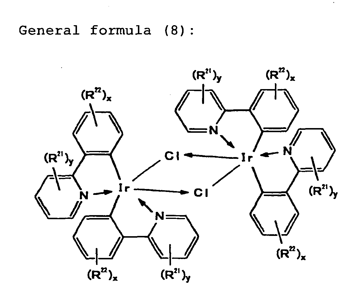


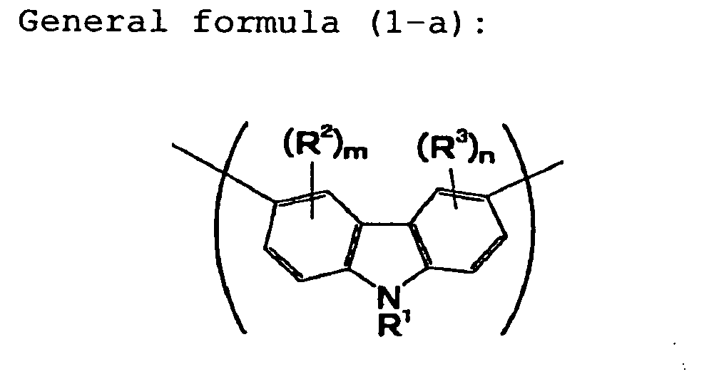 wherein R4 is an alkyl group, R5 and R6 are, independently of each other, a monovalent organic group and may be the same or different from each other, p is an integer of 0 to 3, and q is an integer of 0 to 3, and;


 wherein R10 and R11 are, independently of each other, a monovalent organic group and may be the same or different from each other, R12 and R13 are, independently of each other, a monovalent organic group and may be the same or different from each other, t is an integer of 0 to 3, u is an integer of 0 to 3, v is an integer of 0 to 4, and w is an integer of 0 to 4.
