EP1468952A1 - Sloped part high-speed escalator - Google Patents
Sloped part high-speed escalator Download PDFInfo
- Publication number
- EP1468952A1 EP1468952A1 EP02790779A EP02790779A EP1468952A1 EP 1468952 A1 EP1468952 A1 EP 1468952A1 EP 02790779 A EP02790779 A EP 02790779A EP 02790779 A EP02790779 A EP 02790779A EP 1468952 A1 EP1468952 A1 EP 1468952A1
- Authority
- EP
- European Patent Office
- Prior art keywords
- riser
- tread
- steps
- inclined portion
- disposed
- Prior art date
- Legal status (The legal status is an assumption and is not a legal conclusion. Google has not performed a legal analysis and makes no representation as to the accuracy of the status listed.)
- Withdrawn
Links
Images


Classifications
-
- B—PERFORMING OPERATIONS; TRANSPORTING
- B66—HOISTING; LIFTING; HAULING
- B66B—ELEVATORS; ESCALATORS OR MOVING WALKWAYS
- B66B23/00—Component parts of escalators or moving walkways
- B66B23/08—Carrying surfaces
- B66B23/12—Steps
-
- B—PERFORMING OPERATIONS; TRANSPORTING
- B66—HOISTING; LIFTING; HAULING
- B66B—ELEVATORS; ESCALATORS OR MOVING WALKWAYS
- B66B21/00—Kinds or types of escalators or moving walkways
- B66B21/02—Escalators
- B66B21/025—Escalators of variable speed type
Definitions
- the present invention relates to a high-speed inclined portion escalator in which a traveling speed of steps in an intermediate inclined portion is faster than a traveling speed of the steps in an upper landing portion and a lower landing portion.
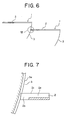
- FIG. 6 is a schematic side elevation showing steps of a conventional normal escalator.
- steps 1 have: a tread 2 for carrying passengers; and a riser 3 disposed on an edge on a downstairs side of the tread 2.
- Figure 7 is a cross section showing a portion VII of Figure 6 enlarged.
- a plurality of tread cleats 2a extending in a direction of travel are disposed on a surface 2c of the tread 2.
- a plurality of riser cleats 3a are disposed on a surface of the riser 3.
- a plurality of pectinate protruding portions 2b are disposed on an edge portion (a demarcation comb) on an opposite side of the tread 2 from the riser 3 for insertion into the riser cleats 3a of an adjacent step.
- the protruding portions 2b are formed continuously on end portions of the tread cleats 2a.
- high-speed inclined portion escalators have been proposed in which it is possible for the amount of time spent riding the escalator to be shortened by operating at low speed in upper and lower landing portions where the passengers get on and of f , operating to accelerate and decelerate in an upper curved portion and a lower curved portion, and operating at high speed in an intermediate inclined portion.
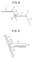
- FIG 8 is a schematic side elevation showing steps of a conventional high-speed inclined portion escalator.
- steps 4 have: a tread 5 for carrying passengers; and a riser 6 disposed on an edge on a downstairs side of the tread 5.
- a pitch between adjacent step 4 or more precisely, a pitch between step link roller shafts (not shown) mounted to the steps 4 to support step link rollers disposed to bear the steps 4 is changed.
- the pitch between the steps 4 is reduced in the upper and lower landing portions, and the pitch between the steps 4 is increased in the intermediate inclined portion.
- a surface of the riser 6 forms an obtuse angle ⁇ relative to the tread of the step 4 adjacent on a lower side in the intermediate inclined portion. In other words, the riser 6 protrudes outward toward the step 4 adjacent on the downstairs side.
- Figure 9 is a cross section showing a portion IX of Figure 8 enlarged.
- a plurality of tread cleats 5a extending in the direction of travel are disposed on a surface of the tread 5.
- a plurality of riser cleats 6a are disposed on a surface of the riser 6.
- a plurality of pectinate protruding portions 5b are disposed on an edge portion on an opposite side of the tread 5 from the riser 6 for insertion into the riser cleats 6a of an adjacent step.
- the present invention aims to solve the above problems and an object of the present invention is to provide a high-speed inclined portion escalator enabling protruding portions on an edge portion of a tread to intermesh sufficiently with riser cleats even if a riser protrudes outward toward a step adjacent on a downstairs side.
- a high-speed inclined portion escalator including: a cyclic path including an upper landing portion, a lower landing portion, and an intermediate inclined portion positioned between the upper landing portion and the lower landing portion; and a plurality of steps linked endlessly and moved cyclically along the cyclic path, the steps having a tread for carrying passengers is disposed, and a riser disposed on an edge of the tread, wherein a traveling speed of the steps in the intermediate inclined portion is set so as to be faster than a traveling speed of the steps in the upper landing portion and the lower landing portion, the riser protrudes outward toward an adjacent step on a downstairs side in the intermediate inclined portion so as to form an obtuse angle relative to the tread of the adjacent step, a plurality of riser cleats are disposed on a surface of the riser, a plurality of protruding portions inserted into the riser cleats are disposed on an edge portion of the tread, and
- Figure 1 is a schematic side elevation showing a high-speed inclined portion escalator according to Embodiment 1 of the present invention.
- a plurality of steps 12 linked endlessly are disposed on a main frame 11.
- the steps 12 are driven by a drive unit (a step driving means) 13, and are moved cyclically.
- a cyclic path for the steps 12 has: a forward section, a return section, an upper inversion portion, and a lower inversion portion.
- the forward section of the cyclic path includes: an upper landing portion (an upper horizontal portion) A, an upper curved portion B, an intermediate inclined portion (a constant inclination portion) C, a lower curved portion D, and a lower landing portion (a lower horizontal portion) E.
- the steps 12 have: a tread 14 for carrying passengers; and a straight riser 15 formed on one edge in a depth direction of the tread 14. Adjacent steps 12 are linked to each other by linking mechanisms 16. A pitch between the adjacent step 12 is changed by changing the shape of the linking mechanisms 16.
- a speed of the steps 12 is changed by changing a pitch between step link roller shafts (not shown) disposed on adjacent steps 12. Specifically, the pitch between the step link roller shafts is minimized in the upper landing portion A and the lower landing portion E where the passengers get on and off, and the steps 12 move at low speed. The pitch between the step link roller shafts is maximized in the intermediate inclined portion C, and the steps 12 move at high speed. In addition, the pitch between the step link roller shafts changes in the upper curved portion B and the lower curved portion D, and the steps 12 accelerate or decelerate.
- Figure 2 is a cross section showing part of Figure 1 enlarged.
- a plurality of tread cleats 14b extending in a direction of travel are disposed on an upper surface the tread 2.
- Aplurality of riser cleats 15a are disposed on a surface of the riser 15.
- Apluralityof pectinate protruding portions 14c are disposed on an edge portion (a demarcation comb) on an opposite side of the tread 14 from the riser 15 for insertion into the riser cleats 15a of an adjacent step.
- the protruding portions 14c are formed continuously on end portions of the tread cleats 14b.
- a surface of the riser 15 forms an obtuse angle ⁇ relative to the tread 14a of the step 12 adjacent on the lower side in the intermediate inclined portion C.
- the riser 15 protrudes outward toward the step 4 adjacent on the downstairs side in the intermediate inclined portion C.
- End surfaces 14d of the protruding portions 14c (surfaces facing bottom surfaces 15b of the riser cleats 15a) form an acute angle ⁇ relative to the tread 14a.
- the end surfaces 14d are parallel to an angle of inclination of the riser 15 and the bottom surfaces 15b, and are inserted completely inside the riser cleats 15a.
- the entire end surface 14d is made to form an acute angle relative to the tread 14a, but as shown in Figure 3, for example, a portion 14e forming a right angle and a portion 14f forming an acute angle relative to the tread 14a may also be combined.
- rounding may also be applied to a corner portion 14g between the tread 14a and the end surface 14d.
- the entire end surface 14d may also be made into a gently curved surface.
- the protruding portions 14c may be disposed so as to be integrated with a main body of the tread 14, or they may also be constructed using a different material from the main body.
Landscapes
- Escalators And Moving Walkways (AREA)
Abstract
In a high-speed inclined portion escalator, a traveling
speed of steps in an intermediate inclined portion is set so
as to be faster than a traveling speed of the steps in an upper
landing portion and a lower landing portion. A riser protrudes
outward toward an adjacent step on a downstairs side in the
intermediate inclined portion so as to form an obtuse angle
relative to a tread of the adjacent step. A plurality of riser
cleats are disposed on a surface of the riser. A plurality
of protruding portions inserted into the riser cleats are
disposed on an edge portion of the tread. An end surface of
the protruding portions facing a bottom surface of the riser
cleats forms an acute angle relative to the tread.
Description
The present invention relates to a high-speed inclined
portion escalator in which a traveling speed of steps in an
intermediate inclined portion is faster than a traveling speed
of the steps in an upper landing portion and a lower landing
portion.
Figure 6 is a schematic side elevation showing steps of
a conventional normal escalator. In the figure, steps 1 have:
a tread 2 for carrying passengers; and a riser 3 disposed on
an edge on a downstairs side of the tread 2.
Figure 7 is a cross section showing a portion VII of Figure
6 enlarged. A plurality of tread cleats 2a extending in a
direction of travel are disposed on a surface 2c of the tread
2. A plurality of riser cleats 3a are disposed on a surface
of the riser 3. A plurality of pectinate protruding portions
2b are disposed on an edge portion (a demarcation comb) on an
opposite side of the tread 2 from the riser 3 for insertion
into the riser cleats 3a of an adjacent step. The protruding
portions 2b are formed continuously on end portions of the tread
cleats 2a.
By intermeshing the protruding portions 2b precisely with
the riser cleats 3a, even if the toe of a passenger's shoe contacts
the riser 3, the toe of the shoe is prevented from being pulled
in between the riser 3 and the tread 2. Furthermore,
consideration is also given to promoting caution so that
passengers do not approach the edge portion of the tread 2 by
applying a warning color such as yellow, etc., thereto.
On the other hand, in recent years, a large number of
escalators having high lift ranges have been installed in subway
stations, etc. In escalators of this kind, passengers must
stand still on the steps for a long time, and many passengers
feel uncomfortable. Because of this, escalators that operate
at high speeds have been developed, but there is an upper limit
to the operating speeds thereof for passengers to get on and
off safely.
In answer to this, high-speed inclined portion escalators
have been proposed in which it is possible for the amount of
time spent riding the escalator to be shortened by operating
at low speed in upper and lower landing portions where the
passengers get on and of f , operating to accelerate and decelerate
in an upper curved portion and a lower curved portion, and
operating at high speed in an intermediate inclined portion.
Figure 8 is a schematic side elevation showing steps of
a conventional high-speed inclined portion escalator. In the
figure, steps 4 have: a tread 5 for carrying passengers; and
a riser 6 disposed on an edge on a downstairs side of the tread
5.
In a high-speed inclined portion escalator of this kind,
since a traveling speed of the steps 4 is changed, a pitch between
adjacent step 4, or more precisely, a pitch between step link
roller shafts (not shown) mounted to the steps 4 to support
step link rollers disposed to bear the steps 4 is changed.
Specifically, the pitch between the steps 4 is reduced in the
upper and lower landing portions, and the pitch between the
steps 4 is increased in the intermediate inclined portion.
Together with this, a surface of the riser 6 forms an obtuse
angle relative to the tread of the step 4 adjacent on a lower
side in the intermediate inclined portion. In other words,
the riser 6 protrudes outward toward the step 4 adjacent on
the downstairs side.
Figure 9 is a cross section showing a portion IX of Figure
8 enlarged. A plurality of tread cleats 5a extending in the
direction of travel are disposed on a surface of the tread 5.
A plurality of riser cleats 6a are disposed on a surface of
the riser 6. A plurality of pectinate protruding portions 5b
are disposed on an edge portion on an opposite side of the tread
5 from the riser 6 for insertion into the riser cleats 6a of
an adjacent step.
However, in a conventional high-speed inclined portion
escalator such as described above, since the surface of the
riser 6 forms an obtuse angle relative to the tread of the
step 4 adjacent on the lower side in the intermediate inclined
portion, corner portions 5c of the protruding portions 5b are
exposed from the riser cleats 6a. Furthermore, if a depth of
the riser cleats 6a is increased in order to insert the protruding
portions 5b completely inside the riser cleats 6a, a length
of the protruding portions 5b must also be increased, making
it easy for the protruding portions 5b to be damaged.
The present invention aims to solve the above problems
and an object of the present invention is to provide a high-speed
inclined portion escalator enabling protruding portions on an
edge portion of a tread to intermesh sufficiently with riser
cleats even if a riser protrudes outward toward a step adjacent
on a downstairs side.
In order to achieve the above object, according to one
aspect of the present invention, there is provided a high-speed
inclined portion escalator including: a cyclic path including
an upper landing portion, a lower landing portion, and an
intermediate inclined portion positioned between the upper
landing portion and the lower landing portion; and a plurality
of steps linked endlessly and moved cyclically along the cyclic
path, the steps having a tread for carrying passengers is
disposed, and a riser disposed on an edge of the tread, wherein
a traveling speed of the steps in the intermediate inclined
portion is set so as to be faster than a traveling speed of
the steps in the upper landing portion and the lower landing
portion, the riser protrudes outward toward an adjacent step
on a downstairs side in the intermediate inclined portion so
as to form an obtuse angle relative to the tread of the adjacent
step, a plurality of riser cleats are disposed on a surface
of the riser, a plurality of protruding portions inserted into
the riser cleats are disposed on an edge portion of the tread,
and an end surface of the protruding portions facing a bottom
surface of the riser cleats forms an acute angle relative to
the tread.
Preferred embodiments of the present invention will now
be explained with reference to the drawings.
Figure 1 is a schematic side elevation showing a high-speed
inclined portion escalator according to Embodiment 1 of the
present invention. In the figure, a plurality of steps 12 linked
endlessly are disposed on a main frame 11. The steps 12 are
driven by a drive unit (a step driving means) 13, and are moved
cyclically.
A cyclic path for the steps 12 has: a forward section,
a return section, an upper inversion portion, and a lower
inversion portion. The forward section of the cyclic path
includes: an upper landing portion (an upper horizontal
portion) A, an upper curved portion B, an intermediate inclined
portion (a constant inclination portion) C, a lower curved
portion D, and a lower landing portion (a lower horizontal
portion) E.
The steps 12 have: a tread 14 for carrying passengers;
and a straight riser 15 formed on one edge in a depth direction
of the tread 14. Adjacent steps 12 are linked to each other
by linking mechanisms 16. A pitch between the adjacent step
12 is changed by changing the shape of the linking mechanisms
16.
A speed of the steps 12 is changed by changing a pitch
between step link roller shafts (not shown) disposed on adjacent
steps 12. Specifically, the pitch between the step link roller
shafts is minimized in the upper landing portion A and the lower
landing portion E where the passengers get on and off, and the
steps 12 move at low speed. The pitch between the step link
roller shafts is maximized in the intermediate inclined portion
C, and the steps 12 move at high speed. In addition, the pitch
between the step link roller shafts changes in the upper curved
portion B and the lower curved portion D, and the steps 12
accelerate or decelerate.
Next, Figure 2 is a cross section showing part of Figure
1 enlarged. In the figure, a plurality of tread cleats 14b
extending in a direction of travel are disposed on an upper
surface the tread 2. Aplurality of riser cleats 15a are disposed
on a surface of the riser 15. Apluralityof pectinate protruding
portions 14c are disposed on an edge portion (a demarcation
comb) on an opposite side of the tread 14 from the riser 15
for insertion into the riser cleats 15a of an adjacent step.
The protruding portions 14c are formed continuously on end
portions of the tread cleats 14b.
A surface of the riser 15 forms an obtuse angle relative
to the tread 14a of the step 12 adjacent on the lower side in
the intermediate inclined portion C. In other words, the riser
15 protrudes outward toward the step 4 adjacent on the downstairs
side in the intermediate inclined portion C. End surfaces 14d
of the protruding portions 14c (surfaces facing bottom surfaces
15b of the riser cleats 15a) form an acute angle α relative
to the tread 14a. Thus, the end surfaces 14d are parallel to
an angle of inclination of the riser 15 and the bottom surfaces
15b, and are inserted completely inside the riser cleats 15a.
In a high-speed inclined portion escalator of this kind,
since the end surfaces 14d of the protruding portions 14c form
an acute angle α relative to the tread 14a, even if a riser
protrudes outward toward a step adjacent on a downstairs side,
the protruding portions 14c of the tread 14 can intermesh with
the riser cleats 15a sufficiently. Consequently, even if the
toe of a passenger's shoe contacts the riser 15, the toe of
the shoe is prevented from being pulled in between the riser
15 and the tread 14.
Furthermore, the intermeshing between the protruding
portions 14c and the riser cleats 15a will not be dislodged
even if subjected to influences such as manufacturing errors,
installation errors, or deformation due to load, etc., in
component parts driving and guiding the steps 12.
Moreover, in Embodiment 1, the entire end surface 14d
is made to form an acute angle relative to the tread 14a, but
as shown in Figure 3, for example, a portion 14e forming a right
angle and a portion 14f forming an acute angle relative to the
tread 14a may also be combined.
As shown in Figure 4, for example, rounding (a curved
portion) may also be applied to a corner portion 14g between
the tread 14a and the end surface 14d.
In addition, as shown in Figure 5, for example, the entire
end surface 14d may also be made into a gently curved surface.
Furthermore, the protruding portions 14c may be disposed
so as to be integrated with a main body of the tread 14, or
they may also be constructed using a different material from
the main body.
Claims (2)
- A high-speed inclined portion escalator comprising:wherein a traveling speed of the steps in the intermediate inclined portion is set so as to be faster than a traveling speed of the steps in the upper landing portion and the lower landing portion;a cyclic path including an upper landing portion, a lower landing portion, and an intermediate inclined portion positioned between the upper landing portion and the lower landing portion; anda pluralityof steps linked endlessly and moved cyclically along the cyclic path, the steps having a tread for carrying passengers is disposed, and a riser disposed on an edge of the tread,
the riser protrudes outward toward an adjacent step on a downstairs side in the intermediate inclined portion so as to form an obtuse angle relative to the tread of the adjacent step;
a plurality of riser cleats are disposed on a surface of the riser;
a plurality of protruding portions inserted into the riser cleats are disposed on an edge portion of the tread; and
an end surface of the protruding portions facing a bottom surface of the riser cleats forms an acute angle relative to the tread. - The high-speed inclined portion escalator according to Claim 1, wherein rounding is applied to a corner portion between the end surface and the tread.
Applications Claiming Priority (3)
| Application Number | Priority Date | Filing Date | Title |
|---|---|---|---|
| JP2002012174A JP2003212461A (en) | 2002-01-21 | 2002-01-21 | Inclined high-speed escalator |
| JP2002012174 | 2002-01-21 | ||
| PCT/JP2002/013129 WO2003062121A1 (en) | 2002-01-21 | 2002-12-16 | Sloped part high-speed escalator |
Publications (2)
| Publication Number | Publication Date |
|---|---|
| EP1468952A1 true EP1468952A1 (en) | 2004-10-20 |
| EP1468952A4 EP1468952A4 (en) | 2007-05-09 |
Family
ID=27606034
Family Applications (1)
| Application Number | Title | Priority Date | Filing Date |
|---|---|---|---|
| EP02790779A Withdrawn EP1468952A4 (en) | 2002-01-21 | 2002-12-16 | HIGH SPEED MECHANICAL STAIRCASE, INCLUDING |
Country Status (4)
| Country | Link |
|---|---|
| EP (1) | EP1468952A4 (en) |
| JP (1) | JP2003212461A (en) |
| CN (1) | CN1547551A (en) |
| WO (1) | WO2003062121A1 (en) |
Families Citing this family (1)
| Publication number | Priority date | Publication date | Assignee | Title |
|---|---|---|---|---|
| WO2012085957A1 (en) * | 2010-12-20 | 2012-06-28 | 株式会社 日立製作所 | Passenger conveyor and steps for passenger conveyor |
Family Cites Families (4)
| Publication number | Priority date | Publication date | Assignee | Title |
|---|---|---|---|---|
| JPS51116586A (en) * | 1975-04-07 | 1976-10-14 | Hitachi Ltd | Escalator |
| DE3764391D1 (en) * | 1986-02-07 | 1990-09-27 | Inventio Ag | ESCALATOR WITH VARIABLE SPEEDS. |
| JP2540965B2 (en) * | 1990-01-16 | 1996-10-09 | 三菱電機株式会社 | Intermediate high-speed escalator |
| JPH0459590A (en) * | 1990-06-27 | 1992-02-26 | Toshiba Corp | Intermediate accelerating man conveyer |
-
2002
- 2002-01-21 JP JP2002012174A patent/JP2003212461A/en not_active Withdrawn
- 2002-12-16 WO PCT/JP2002/013129 patent/WO2003062121A1/en not_active Ceased
- 2002-12-16 EP EP02790779A patent/EP1468952A4/en not_active Withdrawn
- 2002-12-16 CN CNA028158172A patent/CN1547551A/en active Pending
Also Published As
| Publication number | Publication date |
|---|---|
| EP1468952A4 (en) | 2007-05-09 |
| JP2003212461A (en) | 2003-07-30 |
| CN1547551A (en) | 2004-11-17 |
| WO2003062121A1 (en) | 2003-07-31 |
Similar Documents
| Publication | Publication Date | Title |
|---|---|---|
| US8721949B2 (en) | Modular handrail construction for a passenger conveyor handrail | |
| KR0147083B1 (en) | Accelerated Moving Walkway | |
| EP0630850A2 (en) | Escalator step | |
| EP1468952A1 (en) | Sloped part high-speed escalator | |
| CN100418871C (en) | Inclined high-speed escalator | |
| EP0424209B1 (en) | Escalator with verical planar step risers and constant horizontal velocity | |
| US7104386B2 (en) | Sloped part high-speed escalator | |
| JP4236846B2 (en) | Inclined part high-speed escalator | |
| JP5695587B2 (en) | Passenger conveyor | |
| EP1761453B1 (en) | Travelator | |
| EP1331194A2 (en) | Escalator with high speed inclined section | |
| EP1468951A1 (en) | Sloped part high-speed escalator | |
| JP3772001B2 (en) | Escalator steps | |
| JP3589103B2 (en) | Moving sidewalk handrail | |
| JP2003095566A (en) | Passenger conveyor | |
| JP3402155B2 (en) | Passenger conveyor equipment | |
| JPH02225288A (en) | Boarding hall of passenger conveyor | |
| EP1479639A1 (en) | Escalator with high-speed inclined section | |
| JPS61192691A (en) | Step for escalator | |
| JP2017222478A (en) | escalator | |
| JP2003128374A (en) | Passenger conveyor | |
| JP2004217317A (en) | Escalator | |
| JPH115680A (en) | Variable speed passenger conveyor | |
| JP2005022800A (en) | Multi-speed man conveyor | |
| JPH11278781A (en) | Passenger conveyor comb structure |
Legal Events
| Date | Code | Title | Description |
|---|---|---|---|
| PUAI | Public reference made under article 153(3) epc to a published international application that has entered the european phase |
Free format text: ORIGINAL CODE: 0009012 |
|
| 17P | Request for examination filed |
Effective date: 20040116 |
|
| AK | Designated contracting states |
Kind code of ref document: A1 Designated state(s): AT BE BG CH CY CZ DE DK EE ES FI FR GB GR IE IT LI LU MC NL PT SE SI SK TR |
|
| RAP1 | Party data changed (applicant data changed or rights of an application transferred) |
Owner name: MITSUBISHI DENKI KABUSHIKI KAISHA |
|
| A4 | Supplementary search report drawn up and despatched |
Effective date: 20070411 |
|
| STAA | Information on the status of an ep patent application or granted ep patent |
Free format text: STATUS: THE APPLICATION HAS BEEN WITHDRAWN |
|
| 18W | Application withdrawn |
Effective date: 20070524 |