EP1468879A1 - Air bag system - Google Patents
Air bag system Download PDFInfo
- Publication number
- EP1468879A1 EP1468879A1 EP03734827A EP03734827A EP1468879A1 EP 1468879 A1 EP1468879 A1 EP 1468879A1 EP 03734827 A EP03734827 A EP 03734827A EP 03734827 A EP03734827 A EP 03734827A EP 1468879 A1 EP1468879 A1 EP 1468879A1
- Authority
- EP
- European Patent Office
- Prior art keywords
- igniter
- air bag
- capacitor
- bag system
- plural
- Prior art date
- Legal status (The legal status is an assumption and is not a legal conclusion. Google has not performed a legal analysis and makes no representation as to the accuracy of the status listed.)
- Withdrawn
Links
Images








Classifications
-
- B—PERFORMING OPERATIONS; TRANSPORTING
- B60—VEHICLES IN GENERAL
- B60R—VEHICLES, VEHICLE FITTINGS, OR VEHICLE PARTS, NOT OTHERWISE PROVIDED FOR
- B60R21/00—Arrangements or fittings on vehicles for protecting or preventing injuries to occupants or pedestrians in case of accidents or other traffic risks
- B60R21/01—Electrical circuits for triggering passive safety arrangements, e.g. airbags, safety belt tighteners, in case of vehicle accidents or impending vehicle accidents
- B60R21/017—Electrical circuits for triggering passive safety arrangements, e.g. airbags, safety belt tighteners, in case of vehicle accidents or impending vehicle accidents including arrangements for providing electric power to safety arrangements or their actuating means, e.g. to pyrotechnic fuses or electro-mechanic valves
- B60R21/0173—Diagnostic or recording means therefor
-
- B—PERFORMING OPERATIONS; TRANSPORTING
- B60—VEHICLES IN GENERAL
- B60R—VEHICLES, VEHICLE FITTINGS, OR VEHICLE PARTS, NOT OTHERWISE PROVIDED FOR
- B60R21/00—Arrangements or fittings on vehicles for protecting or preventing injuries to occupants or pedestrians in case of accidents or other traffic risks
- B60R21/02—Occupant safety arrangements or fittings, e.g. crash pads
- B60R21/16—Inflatable occupant restraints or confinements designed to inflate upon impact or impending impact, e.g. air bags
- B60R21/26—Inflatable occupant restraints or confinements designed to inflate upon impact or impending impact, e.g. air bags characterised by the inflation fluid source or means to control inflation fluid flow
-
- B—PERFORMING OPERATIONS; TRANSPORTING
- B60—VEHICLES IN GENERAL
- B60R—VEHICLES, VEHICLE FITTINGS, OR VEHICLE PARTS, NOT OTHERWISE PROVIDED FOR
- B60R21/00—Arrangements or fittings on vehicles for protecting or preventing injuries to occupants or pedestrians in case of accidents or other traffic risks
- B60R21/02—Occupant safety arrangements or fittings, e.g. crash pads
- B60R21/16—Inflatable occupant restraints or confinements designed to inflate upon impact or impending impact, e.g. air bags
- B60R21/26—Inflatable occupant restraints or confinements designed to inflate upon impact or impending impact, e.g. air bags characterised by the inflation fluid source or means to control inflation fluid flow
- B60R21/264—Inflatable occupant restraints or confinements designed to inflate upon impact or impending impact, e.g. air bags characterised by the inflation fluid source or means to control inflation fluid flow using instantaneous generation of gas, e.g. pyrotechnic
- B60R21/2644—Inflatable occupant restraints or confinements designed to inflate upon impact or impending impact, e.g. air bags characterised by the inflation fluid source or means to control inflation fluid flow using instantaneous generation of gas, e.g. pyrotechnic using only solid reacting substances, e.g. pellets, powder
-
- F—MECHANICAL ENGINEERING; LIGHTING; HEATING; WEAPONS; BLASTING
- F42—AMMUNITION; BLASTING
- F42B—EXPLOSIVE CHARGES, e.g. FOR BLASTING, FIREWORKS, AMMUNITION
- F42B3/00—Blasting cartridges, i.e. case and explosive
- F42B3/10—Initiators therefor
- F42B3/12—Bridge initiators
- F42B3/121—Initiators with incorporated integrated circuit
-
- B—PERFORMING OPERATIONS; TRANSPORTING
- B60—VEHICLES IN GENERAL
- B60R—VEHICLES, VEHICLE FITTINGS, OR VEHICLE PARTS, NOT OTHERWISE PROVIDED FOR
- B60R21/00—Arrangements or fittings on vehicles for protecting or preventing injuries to occupants or pedestrians in case of accidents or other traffic risks
- B60R21/01—Electrical circuits for triggering passive safety arrangements, e.g. airbags, safety belt tighteners, in case of vehicle accidents or impending vehicle accidents
- B60R2021/0104—Communication circuits for data transmission
- B60R2021/01047—Architecture
- B60R2021/01054—Bus
- B60R2021/01075—Bus between the airbag control unit and pyrotechnic fuses or equivalent actuators
-
- B—PERFORMING OPERATIONS; TRANSPORTING
- B60—VEHICLES IN GENERAL
- B60R—VEHICLES, VEHICLE FITTINGS, OR VEHICLE PARTS, NOT OTHERWISE PROVIDED FOR
- B60R21/00—Arrangements or fittings on vehicles for protecting or preventing injuries to occupants or pedestrians in case of accidents or other traffic risks
- B60R21/02—Occupant safety arrangements or fittings, e.g. crash pads
- B60R21/16—Inflatable occupant restraints or confinements designed to inflate upon impact or impending impact, e.g. air bags
- B60R21/26—Inflatable occupant restraints or confinements designed to inflate upon impact or impending impact, e.g. air bags characterised by the inflation fluid source or means to control inflation fluid flow
- B60R2021/26029—Ignitors
-
- B—PERFORMING OPERATIONS; TRANSPORTING
- B60—VEHICLES IN GENERAL
- B60R—VEHICLES, VEHICLE FITTINGS, OR VEHICLE PARTS, NOT OTHERWISE PROVIDED FOR
- B60R21/00—Arrangements or fittings on vehicles for protecting or preventing injuries to occupants or pedestrians in case of accidents or other traffic risks
- B60R21/02—Occupant safety arrangements or fittings, e.g. crash pads
- B60R21/16—Inflatable occupant restraints or confinements designed to inflate upon impact or impending impact, e.g. air bags
- B60R21/26—Inflatable occupant restraints or confinements designed to inflate upon impact or impending impact, e.g. air bags characterised by the inflation fluid source or means to control inflation fluid flow
- B60R21/263—Inflatable occupant restraints or confinements designed to inflate upon impact or impending impact, e.g. air bags characterised by the inflation fluid source or means to control inflation fluid flow using a variable source, e.g. plural stage or controlled output
- B60R2021/2633—Inflatable occupant restraints or confinements designed to inflate upon impact or impending impact, e.g. air bags characterised by the inflation fluid source or means to control inflation fluid flow using a variable source, e.g. plural stage or controlled output with a plurality of inflation levels
-
- B—PERFORMING OPERATIONS; TRANSPORTING
- B60—VEHICLES IN GENERAL
- B60R—VEHICLES, VEHICLE FITTINGS, OR VEHICLE PARTS, NOT OTHERWISE PROVIDED FOR
- B60R21/00—Arrangements or fittings on vehicles for protecting or preventing injuries to occupants or pedestrians in case of accidents or other traffic risks
- B60R21/02—Occupant safety arrangements or fittings, e.g. crash pads
- B60R21/16—Inflatable occupant restraints or confinements designed to inflate upon impact or impending impact, e.g. air bags
- B60R21/26—Inflatable occupant restraints or confinements designed to inflate upon impact or impending impact, e.g. air bags characterised by the inflation fluid source or means to control inflation fluid flow
- B60R21/264—Inflatable occupant restraints or confinements designed to inflate upon impact or impending impact, e.g. air bags characterised by the inflation fluid source or means to control inflation fluid flow using instantaneous generation of gas, e.g. pyrotechnic
- B60R21/2644—Inflatable occupant restraints or confinements designed to inflate upon impact or impending impact, e.g. air bags characterised by the inflation fluid source or means to control inflation fluid flow using instantaneous generation of gas, e.g. pyrotechnic using only solid reacting substances, e.g. pellets, powder
- B60R2021/2648—Inflatable occupant restraints or confinements designed to inflate upon impact or impending impact, e.g. air bags characterised by the inflation fluid source or means to control inflation fluid flow using instantaneous generation of gas, e.g. pyrotechnic using only solid reacting substances, e.g. pellets, powder comprising a plurality of combustion chambers or sub-chambers
Definitions
- the present invention relates to an air bag system using a bus system.
- the present invention relates to an integrated circuit for an air bag system used in an air bag system using a bus system and a method for controlling operation of an air bag system using the same.
- the present invention relates to an igniter for an air bag system used in an air bag system using a bus system and a method for controlling operation of an air bag system using the same.
- the present invention relates to a method of charging a capacitor provided in an igniter for an air bag system.
- An air bag system for protecting a passenger from an impact at a time of collision of a vehicle is indispensable, and the air bag system needs to be reduced in weight from a demand for reducing weight of a whole vehicle.
- kinds and the total number of air bags such as an air bag for a driver side, an air bag for a passenger side next to the driver, an air bag for a rear seat side, and an air bag for an side impact are increasing, and therefore, a lighter air bag system is in greater demand.
- an electronic control unit connected to a power source (a battery in a vehicle) and an impact detecting sensor are individually connected to individual gas generators (a gas generator and an air bag are accommodated in a module case).
- a power source a battery in a vehicle
- an impact detecting sensor is individually connected to individual gas generators (a gas generator and an air bag are accommodated in a module case).
- An aspect of the connection between the ECU and the individual gas generators is shown in Fig. 13.
- the ECU and an igniter (Fig. 15) of each of the individual gas generators are necessarily connected to each other through two conductors, and thereby, conductors double the number of the total number of igniters are required. Having many conductors contributes largely to weight increase in an air bag system.
- the ECU and the individual gas generators are not connected by only the conductors but connected by connecting plural conductors via plural connectors, and thereby, there occurs a serious problem such as a weight increase due to use of the connectors and a cost increase due to increase of the number of the connectors.
- an air bag system is constituted by providing bus lines comprising plural loop wires passing through the ECU and connecting each of the individual gas generators to the bus line through two conductors (three or more conductors when occasion demands) .
- bus lines comprising plural loop wires passing through the ECU and connecting each of the individual gas generators to the bus line through two conductors (three or more conductors when occasion demands) .
- an integrated circuit receiving information transmission from the ECU and a capacitor supplying a current for activating an igniter are provided in each of the individual gas generators.
- the total number of capacitors is increased, but since the capacitors are distributed and arranged in the ECU and the respective igniters, the capacitance and weight of the capacitor per igniter is reduced.
- An object of the present invention is to provide (I) an air bag system, (II) an integrated circuit for an air bag system and an operation control method of an air bag system utilizing the same, (III) an igniter for an air bag system and an operation control method of an air bag system utilizing the same, and (IV) a method of charging a capacitor provided in an igniter for an air bag system, which achieves a large weight reduction in an entire air bag system by introducing a bus system into the air bag system and that can ensure reliability and rapidness of operation similar to those in a conventional art, and that can obtain a high reliability.
- the present invention provides, as one means for solving the above problem, an air bag system comprising an ECU connected to a power source and an impact detecting sensor, and plural module cases which are connected to the ECU and accommodate plural gas generators and plural air bags, a bus line which comprises plural loop wires passing through the ECU to supply and transmit currents and required information, and individual gas generators which are connected operationally by plural conductors branched at predetermined portions from the bus line, wherein each of the plural gas generators is provided with one or at least two electric igniters including a heat generating portion and a priming coming in contact with the heat generating portion, the one or at least two igniters and the bus line are connected by plural conductors, and further a capacitor and an integrated circuit recorded with information to exhibit required functions are provided for each igniter of each gas generator, and a current for igniting the priming is supplied to the one or at least two igniters through the capacitor in the igniter, and a time period for supplying a current is the time period from the point where a
- the numbers of the loop wires forming the bus line and the conductors for connecting the bus line and the gas generators may be two, three, or four or more, respectively, and two is preferable in view of simplifying the entire system.
- the priming is not limited to a specific one, but a combination of a metal or the like and an oxidizing agent such as perchlorate is preferable, a combination of a metal such as zirconium, titanium, and hafnium and perchlorate is more preferable, and a mixture (ZPP) of zirconium and potassium perchlorate is particularly preferable. Desirably, the ZPP is formed in particle shape and particle diameters of zirconium and potassium perchlorate are adjusted.
- a capacitance of the capacitor is preferably not more than 24 ⁇ F, more preferably not more than 12 ⁇ F, and further preferably not more than 6 ⁇ F.
- the maximum current value in the time period for supplying a current means a current value sufficient for igniting a priming, and if the current value is not more than 5% of the maximum current value, the priming cannot be ignited.
- a current for activating an igniter flows from a power source (a battery) with a relatively large capacitance at 1.2 A for about 2msec, that is, at a relatively low current for a relatively long time
- a waveform of an ignition current (a vertical axis denotes a current value (A) and a horizontal axis denotes a time ( ⁇ sec)) becomes rectangular.
- a relationship (t/T) between these t and T is in the range of 0 ⁇ t/T ⁇ 0.2 or 0.5 ⁇ t/T ⁇ 1.
- a waveform of a current is similar to a discharging waveform (a waveform similar to a triangle) obtained when electricity stored in the capacitor is applied to the heat generating portion directly.
- a waveform of a current is similar to a waveform (a waveform similar to a trapezoid) obtained when a discharging waveform is converted through a discharging waveform converting circuit (hereinafter, abbreviated as "a waveform converting circuit") for converting a waveform of a current stored in a capacitor to a signal waveform of a current for igniting the priming or the like.
- the period for supplying a current is as described above, and it is preferably within 200 ⁇ sec, and more preferably within 100 ⁇ sec.
- a current value at this time varies depending on a resistance value of the heat generating portion in the igniter, and it is determined on the basis of presence or absence of the waveform converting circuit, the constitution of the waveform converting circuit, a particle diameter of a priming, a shape of the heat generating portion and the like.
- the respective igniters of the respective gas generators are provided with a capacitor and an integrated circuit having a predetermined function, and preferably, a waveform converting circuit is further included.
- This waveform converting circuit functions to convert the discharging waveform represented by the formula (I) to a triangular waveform or a trapezoidal waveform.
- a coil can be interposed in a connecting circuit between the capacitor and the heat generating portion, and further, the discharging waveform converting circuit can be provided in the integrated circuit in view of simplifying of the entire system.
- a circuit for preventing the igniter from being activated erroneously due to a noise generated outside the igniter for example, a varistor (non-linear resistance element) can be provided.
- the integrated circuit recorded with information to exhibit required functions the one recorded with information for exhibiting one or at least two functions selected from the group of a function for detecting abnormality of the heat generating portion of the igniter in the gas generator, an function for identifying each of the plural gas generators and a function for detecting a malfunction of the capacitor can be used. It is further preferable that a circuit (a circuit which exhibits a noise preventing function) for preventing the igniter from being activated erroneously due to a noise generated outside the igniter is provided in the igniter.
- the integrated circuit is provided with a basic function to activate a proper gas generator for protecting the passenger according to a situation of a vehicle collision upon receiving a signal from the ECU.
- a proper gas generator for protecting the passenger according to a situation of a vehicle collision upon receiving a signal from the ECU.
- the present invention provides, as one means for solving the above problem, an air bag system comprising an ECU connected to a power source and an impact detecting sensor, and plural module cases which are connected to the ECU and accommodate plural gas generators and plural air bags, a bus line which comprises plural loop wires (for example, two or three or four or more, preferably two wires) passing through the ECU to supply and transmit currents and required information, and individual gas generators which are connected operationally by plural conductors branched at predetermined portions from the bus line, wherein each of the plural gas generators is provided with one or at least two electric igniters including a heat generating portion and a priming coming in contact with the heat generating portion, the one or at least two igniters and the bus line are connected by plural conductors (for example, two or three or four or more, preferably two conductors), a capacitor, an integrated circuit in which information for developing a required function is stored, and the heat generating portion are provided on one substrate in each igniter of each gas generator, and the substrate is provided
- an air bag system comprising an electronic control unit connected to a power source and an impact detecting sensor, and plural module cases which are connected to the electronic control unit and accommodate plural gas generators and plural air bags, a bus line which comprises plural loop wires (for example, two or three or four or more, preferably two wires) passing through the electronic control unit to supply and transmit currents and required information, and individual gas generators which are connected operationally by plural conductors branched at predetermined portions from the bus line, wherein each of the plural gas generators is provided with one or at least two electric igniters including a heat generating portion and a priming coming in contact with the heat generating portion, the one or at least two igniters and the bus line are connected by plural conductors (for example, two or three or four or more, preferably two conductors), each igniter of each gas generator has a capacitor and an integrated circuit in which information for developing a required function on one substrate, and the substrate is provided vertically, a header,
- the respective igniters of the respective gas generators are provided with a capacitor and an integrated circuit having a required function, and preferably, a waveform converting circuit is further provided.
- the integrated circuit (and the waveform converting circuit, if required) is provided on one surface of the substrate and the capacitor (and the waveform converting circuit, if required) is provided on the other surface.
- the heat generating portion may be provided on either surface, but desirably, it is provided on the same surface as the integrated circuit to facilitate circuit formation (a soldering work). Further, if the waveform converting circuit is provided, preferably, it is provided in the integrated circuit in view of simplifying the entire system.
- such a structure can be employed that the substrate is fitted to penetrate a header for forming a priming holding space together with a cup member for holding the priming, and the capacitor and the integrated circuit are positioned below the header, and the heat generating portion projects above the header to come into contact with the priming.
- various method can be employed such that a method for welding a wire for heat generation comprising a platinum/tungsten alloy, nickel/chrome alloy or the like on the header to fix the heat generating portion, a method for forming the heat generating portion by etching after pasting a foil comprising the alloy on an insulating substrate comprising an aluminum with oxidized coating, a glass, epoxy resin, phenol resin, polyimide or the like, a method for forming the heat generating portion by performing vapor deposition of an electroconductive material on a pattern-masked insulating substrate, or a method for printing electrical electroconductive material on an insulating substrate.
- the integrated circuit and the capacitor By providing the integrated circuit and the capacitor on different surfaces of the substrate in this manner, a compact structure can be achieved as compared with a case of providing on one surface. Further, by providing the priming above the header and providing the substrate below the header, the integrated circuit or the capacitor does not come in contact with the priming, so that pollution of the capacitor or the integrated circuit due to the priming can be prevented and, in addition thereto, a possibility of erroneous activation of the igniter can also be eliminated.
- the integrated circuit and the capacitor (and the discharging waveform converting circuit, if required) are provided on one surface of the substrate.
- the heat generating portion may be provided on either surface, but desirably, it is on the same surface as the integrated circuit and the capacitor.
- such a structure can be employed that a portion of the substrate except for the heat generating portion is sealed with thermoplastic resin containing glass fibers, thermosetting resin such as epoxy resin, organic and inorganic insulating material such as glass, and the heat generating portion is in contact with the priming.
- thermoplastic resin containing glass fibers thermosetting resin such as epoxy resin, organic and inorganic insulating material such as glass
- the heat generating portion is in contact with the priming.
- the capacitor and the integrated circuit are protected and the capacitor and the integrated circuit do not come in contact with the priming, and thereby, pollution of the capacitor and the integrated circuit due to the priming can be prevented.
- an electroconductive pattern is formed on a substrate by etching, including connecting portions which connect the integrated circuit with the heat generating portion, the capacitor and the bus line, and also including the heat generating portion of the igniter.
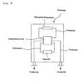
- the conductor pattern forming the connecting portions which connect the integrated circuit with the heat generating portion, the capacitor and the bus line can be two routes for each connecting portion, i.e., the total six routes as shown in Fig. 8 and Fig. 9.
- the etching wet etching, dry etching (plasma etching, sputter etching, reactive ion etching) photo etching or the like can be applied.
- the present invention provides, as one means for solving the above problem, an air bag system comprising an ECU connected to a power source and an impact detecting sensor, and plural module cases which are connected to the ECU and accommodate plural gas generators and plural air bags, a bus line which comprises plural loop wires (for example, two or three or four or more, preferably two wires) passing through the ECU to supply and transmit currents and required information, and individual gas generators which are connected operationally by plural conductors branched at predetermined portions from the bus line, wherein each of the plural gas generators is provided with one or at least two electric igniters including a heat generating portion and a priming coming in contact with the heat generating portion, the one or at least two igniters and the bus line are connected by plural conductors (for example, two or three or four or more, preferably two conductors), and each igniter of each gas generator is provided with an integrated circuit in which information for exhibiting a function for detecting abnormality of the heat generating portion.
- a bus line which comprises plural
- the capacitor can be provided together with the integrated circuit and the heat generating portion, and abnormality of the heat generating portion of the igniter to be detected includes failure in line or a loose connection between the heat generating portion and the priming, or abnormality of a resistance value of the heat generating portion and the like.
- the heat generating portion of the igniter and the priming have to be connected properly (the heat generating portion and the priming are brought in pressure-contact with each other). For example, if there is a gap between the heat generating portion and the priming, such malfunctions may be occur that, though the igniter is actuated, the priming is not ignited or a ignition is delayed. Further, similar malfunctions may occur when the heat generated portion is disconnected or is connected loosely. For this reason, by recording information for detecting the malfunction in the integrated circuit, an inferior product can be eliminated at a time of shipping, and by detecting abnormality at a practical use (while driving a vehicle), a prompt exchange can be performed.
- Detecting theory for abnormality of the heat generating portion is as follows: when contacting state of a heat generating portion and a priming is good, most part of calorie generated by flowing of a constant current is conducted to the priming, so that the temperature of the heat generating portion does not rise so high. On the other hand, when the contacting state of the heat generating portion and the priming is bad, transfer of heat is less, so that the temperature rising of the heat generating portion becomes higher than a normal case.
- a resistance R is measured when a current I of 10 to 15 times of the current i is flowed (the temperature of the heat generating portion becomes about 50 to 100°C, but the priming is not ignited with such a temperature), so that the resistance change due to the temperature change of the heat generating portion is obtained as a voltage change with comparisons of I and i and of R and r.
- abnormality of the heat generating portion is detected by using the air bag system of the above invention, such a method can be employed that abnormality of the heat generating portion of the igniter is detected based on the information inputted in the integrated circuit by supplying and transmitting a current and a command from the ECU to the integrated circuit via a bus line in a normal state in which the gas generator is not activated
- the present invention provides, as one means for solving the above problem, an air bag system comprising an ECU connected to a power source and an impact detecting sensor, and plural module cases which are connected to the ECU and accommodate plural gas generators and plural air bags, a bus line which comprises plural loop wires (for example, two or three or four or more) passing through the ECU to supply and transmit currents and required information, and individual gas generators which are connected operationally by plural conductors branched at predetermined portions from the bus line, wherein each of the plural gas generators is provided with one or at least two electric igniters including a heat generating portion and a priming coming in contact with the heat generating portion, the one or at least two igniters and the bus line are connected by plural conductors (for example, two or three or four or more), and each igniter of each gas generator is provided with an integrated circuit for recording information for exhibiting a function for identifying each of the plural gas generators.
- the capacitor and/or the heat generating portion can be provided together with the integrated circuit.
- gas generators for an air bag
- various kinds of gas generators such as one for a driver side, one for a passenger side next to the driver, one for a side impact (for a side collision), one for a curtain air bag and the like have been practically used.
- the gas generator for a side impact the total four gas generators are mounted for a driver side, a passenger side next to the driver, two rear seat sides respectively.
- the present invention provides, as one means for solving the above problem, an air bag system comprising an ECU connected to a power source and an impact detecting sensor, and plural module cases which are connected to the ECU and accommodate plural gas generators and plural air bags, a bus line which comprises plural loop wires (for example, two or three or four or more, preferably two wires) passing through the ECU to supply and transmit currents and required information, and individual gas generators which are connected operationally by plural conductors branched at predetermined portions from the bus line, wherein each of the plural gas generators is provided with one or at least two electric igniters including a heat generating portion and a priming coming in contact with the heat generating portion, the one or at least two igniters and the bus line are connected by plural conductors (for example, two or three or four or more, preferably two conductors), and each igniter of each gas generator is provided with an integrated circuit in which information to exhibit a function for detecting the capacitor and a malfunction of the capacitor is recorded.
- the information for developing a function for detecting a malfunction of the capacitor also includes confirmation information of a mounted state (soldered state) of a capacitor to a substrate and the like in addition to information for measuring a pulse response or a dielectric dissipation factor.
- the capacitor After mounted to the vehicle, since the capacitor repeats charging and discharging, the capacitor deteriorates with age. However, abnormality is detected at a time of a practical use (while driving a vehicle) by recording information which can confirm a malfunction due to this deterioration in the integrated circuit in advance, so that a prompt exchange can be performed. Furthermore, by recording information for confirming the soldered state in advance, an inferior product can be removed at a time of shipping.
- the function for detecting a malfunction of the capacitor is exhibited by using the air bag system of the above invention, such a method can be employed that the function for detecting a malfunction of the capacitor is exhibited based on the information inputted in the integrated circuit by supplying and transmitting a current and a command from the ECU to the integrated circuit via a bus line in a normal state in which the gas generator is not activated.
- the present invention provides, as one means for solving the above problem, an air bag system comprising an ECU connected to a power source and an impact detecting sensor, and plural module cases which are connected to the ECU and accommodate plural gas generators and plural air bags, a bus line which comprises plural loop wires (for example, two or three or four or more, preferably two wires) passing through the ECU to supply and transmit currents and required information, and individual gas generators which are connected operationally by plural conductors branched at predetermined portions from the bus line, wherein each of the plural gas generators is provided with one or at least two electric igniters including a heat generating portion and a priming coming in contact with the heat generating portion, the one or at least two igniters and the bus line are connected by plural conductors (for example, two or three or four or more, preferably two conductors), and further, each igniter of each gas generator is provided with an integrated circui t inputted with information to exhibi t required functions, and the inside of the igniter is provided with
- a device constituted to prevent a current from flowing from a vehicle side to an igniter side for example, a diode or a varistor (a non-linear resistance element) as a noise preventing means (a circuit for preventing an igniter from being activated erroneously), the above-described erroneous activation of the igniter can be prevented.
- the present invention provides, as another solving means for the above problem, an air bag system wherein at least two igniters share one capacitor and one integrated circuit inputted with information to exhibit required functions when the air bag system of the above invention has at least two igniters for each of the plural gas generators.
- the at least two igniters share one capacitor and one integrated circuit inputted with information for exhibiting required functions, and further, they share a discharging waveform converting circuit which is provided, if required, to convert a signal waveform of a current for igniting the priming stored in the capacitor for each igniter. And thereby, the entire system can further be reduced in weight.
- the discharging waveform converting circuit may be assembled into the integrated circuit.
- the present invention provides, as another means for solving the problem, an air bag system wherein each igniter has a capacitor and an integrated circuit inputted with information to exhibit required functions, and further has two pins for supplying and transmitting a current and required information to at least two igniters from the bus line when the air bag system of the above invention has at least two igniters for each of the plural gas generators.
- the whole weight of the air bag system can be reduced largely, and an operation performance similar to the conventional one can be secured.
- An air bag system of the present invention achieves reduction in weight of the entire system by using a bus line and achieves reliability of an operation of the system by the above-described solving means.
- Embodiments including the above-described first to ninth solving means will be explained below. In this case, the order of the solving means and the order of embodiments do not coincide with each other necessarily.
- an air bag system of the present invention uses bus lines 10 and 11 comprising two loop wires passing through an ECU.
- the ECU is connected to a power source (a battery in a vehicle) and an impact detecting sensor which are not illustrated, and a capacitor for backup, when a conductor connecting the ECU and the power source is disconnected by an impact at a collision of a vehicle, is disposed.
- the capacitor for backup since the capacitor is disposed at each of respective gas generators (igniters), the capacitor for backup may be one with a small capacitance (i.e. , light weight) , but the capacitor serving for backup in the conventional air bag system shown in Fig. 13 has to have a large capacitance in order to activate all the gas generators by itself at a time of failure in line of a lead wire between the battery and the ECU.
- the bus lines 10 and 11 and gas generators in a required number of module cases (which are indicated by black circles.
- the gas generator and an air bag are accommodated in the case.) mounted to a vehicle are connected by two conductors (or three or more conductors when occasion demands), such that the gas generators can be operational respectively
- Fig. 2 is an axial sectional view of a single type gas generator (an igniter 21) in which one igniter is provided
- Fig. 3 is an axial sectional view of a dual type gas generator (igniters 31 and 32) in which two igniters are provided.
- two (or three or more when occasion demands) pins 21a and 21b are provided in the igniter 21 and they are connected to the bus lines 10 and 11 through a connector 25.
- two (or three or more when occasion demands) pins 31a and 31b are provided in an igniter 31
- two (or three or more when occasion demands) pins 32a and 32b are provided in an igniter 32, and the igniters are respectively connected to the bus lines 10 and 11 through respective connectors 35 and 36.
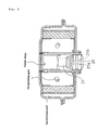
- Fig. 4 shows vertical schematic sectional views of igniters, and since igniters having the same structure can be used as the igniter 21, the igniters 31 and 32, the igniter 21 will be explained below.
- a heat generating portion is provided on a glass header, an igniting agent (for example, ZPP) is charged to come in pressure-contact with the heat generating portion, and a substrate provided with a capacitor and an integrated circuit in which information for developing required functions has been recorded is disposed in a lower portion of the igniter 21.
- the integrated circuit, and the heat generating portion and the capacitor are respectively connected by two conductors, and the integrated circuit is further connected to the pins 21a and 21b through conductors.
- the integrated circuit is recorded with information to inflate a required air bag when a command is received from the ECU at least at a collision of a vehicle.
- information for developing one or at least two functions when required, for example, selected from the groups of a function for detecting abnormality of the heat generating portion of the igniter in the gas generator, a function for identifying each of the plural gas generators and a function for detecting a malfunction of the capacitor can be recorded in the integrated circuit.
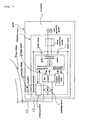
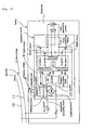
- the substrate in the igniter, as shown in Fig. 4, that is provided with the capacitor or the integrated circuit may be constituted to have each of structures shown with the conceptual diagrams in Fig. 5.
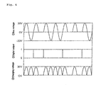
- Fig. 6 shows pulse waveforms of a bus voltage, a digital output and a charging voltage shown in Fig. 5.
- the capacitor and the integrated circuit are provided on the substrate, a waveform converting circuit can be provided thereon, if required, and the waveform converting circuit itself can be incorporated into the integrated circuit.
- the integrated circuit and the capacitor on the substrate are connected to the bus lines 10 and 11 through the pins 21a and 21b.
- a current and information supplied from the bus lines 10 and 11 are sent to the integrated circuit, they are converted to digital outputs by an A/D converter (an analog/digital converter) to be sent to an MCU (a Micro Computer Unit).
- A/D converter an analog/digital converter
- MCU Micro Computer Unit
- a command is sent from the MCU such that charge control information, position identification information, failure-detecting information of a heat generating portion or a resistance value change detecting information is exhibited, and also, the current is used for charging the capacitor, but it is not used for making the heat generating portion generate heat.
- a varistor non-linear resistance element is disposed in a circuit between the MCU and the heat generating portion as noise preventing means, and it serves such that the igniter is not activated erroneously due to a noise generated outside the igniter.
- the heat generating portion is put in contact with the priming, and it generates heat by a current supplied only from the capacitor to ignite the priming.
- failure-detecting information or resistance value change detecting information of the heat generating portion, detecting information for a malfunction of the capacitor, and detecting information about whether or not an igniter including an identifying function required for activating a gas generator detecting information about whether or not an igniter having an identification function for activating a gas generator required for a driver side, a passenger side next to the driver or the like properly at a time of collision is disposed rightly, or whether or not another igniter having the same identifying function is disposed in a duplicated manner
- the ECU the gas generator (the integrated circuit arranged in the igniter) through the bus lines so that whether or not there is abnormality in these members is checked.
- an alarm lamp activated in linkage with the air bag system, or the like informs the abnormality, so that an early exchange of parts can be conducted to recover the safety. Further, the capacitor of each igniter can be charged from the power source.
- a required current is supplied from the capacitor for a predetermined time period (from the point where a current value reaches the current value corresponding to 5% of the maximum current value to the point where the current value is reduced to 5% of the maximum current value which is only within 500 ⁇ sec, and the heat generating portion generates heat to ignite and burn the priming.
- a transfer charge in Fig. 2 or Fig. 3 and further the gas generating agent are ignited and burnt to generate a gas.
- the gas is discharged from gas discharging ports to inflate an air bag accommodated in the module case together with the gas generator.
- An air bag system of this embodiment is characterized in a structure of a substrate on which the integrated circuit and the like is arranged, a state of the disposition or the like.
- a capacitor, an integrated circuit recorded with information to exhibit required functions and a heat generating portion are provided on the substrate, and these members can be arranged on one surface or both surfaces of the substrate.
- such a structure can be employed that the integrated circuit and the heat generating portion are provided on one surface of the substrate, and the capacitor is provided on the other surface.
- the capacitor and the integrated circuit are connected through two conductors inserted into two holes, and the integrated circuit and the heat generating portion are connected through two conductors.
- the integrated circuit is also connected to the bus lines 10 and 11 through two conductors, pins of the igniters or the like.
- such a structure can be employed that the integrated circuit, the heat generating portion and the capacitor are arranged on one surface of the substrate.
- the integrated circuit, the capacitor and the heat generating portion are connected by two conductors respectively, and the integrated circuit is also connected to the bus lines 10 and 11 through two conductors, pins of the igniters or the like.
- An electroconductive pattern is formed on the substrate by etching, including connecting portions, shown in Fig. 7 and Fig. 8, which connect the integrated circuit with the heat generating portion, the capacitor and the bus line, and the heat generating portion as shown in Fig. 9.
- etching including connecting portions, shown in Fig. 7 and Fig. 8, which connect the integrated circuit with the heat generating portion, the capacitor and the bus line, and the heat generating portion as shown in Fig. 9.
- the sealing resin serves as a protection film for the integrated circuit or the capacitor, which is preferable.
- the substrate shown in Fig. 7 is used, but the substrate shown in Fig. 9 can be also used.
- the substrate is provided to stand on the glass header.
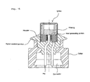
- Fig. 11 The substrate used in Fig. 11 is shown in Fig. 10, but, in the drawing, the priming covering the heat generating portion is deleted and the seating portion of the insulating material is partially cut out.
- the substrate shown in Fig. 10 is used as the substrate in the igniter 21 (having a different shape from the shape shown in Fig. 4) , the substrate is provided to stand on the header, a portion of the substrate except for the heat generating portion is covered with insulating material such as epoxy resin, and the heat generating portion comes in contact with the priming. Contacting surfaces of a substrate bottom surface and the header are fixed by adhesive.
- a space capacity for disposing the substrate can be made smaller than a case of laying the substrate, so that the igniter itself can be reduced in size. Then, since the integrated circuit and the capacitor on the portion of the substrate except for the heat generating portion do not come in contact with the priming, pollution thereof or the like are prevented.
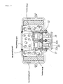
- a glass header for supporting pins 21a and 21b sections vertically between the substrate and the priming, and a substrate arranged with the capacitor and the integrated circuit is provided below the header vertically.
- the heat generating portion is disposed above the header (on a surface of the header) , and the heat generating portion and the substrate are connected by conductors (two pins 22a and 22b).
- the heat generating portion is formed by employing a method for welding a wire for heat generation comprising a platinum/tungsten alloy, nickel/chrome alloy or the like on the header to fix the heat generating portion, or the like.
- the integrated circuit, the capacitor, and the pins 21a and 21b can be connected by a conductor pattern obtained by etching, and the heat generating portion and the integrated circuit can be connected by a conductor pattern obtained by etching.
- a space capacity for disposing the substrate can be made smaller than a case of laying the substrate, so that the igniter itself can be reduce in size. And, since the substrate and the priming do not come in contact with each other, pollution of the integrated circuit or the capacitor or the like can be prevented.
- the air bag system of the second embodiment operates like the air bag system of the first embodiment.
- a capacitor, an integrated circuit recorded with information to exhibit a function for detecting abnormality of a heat generating portion in an igniter, and a heat generating portion of an igniter are disposed on a substrate.
- the information includes failure in line of the heat generating portion, a loose contact between the heat generating portion and the priming and the like.
- the capacitor, the integrated circuit recorded with information to exhibit an function for identifying each of the plural gas generators, and the heat generating portion of the igniter are disposed on the substrate.
- the information to exhibit the above-described identifying function is recorded after the gas generator is assembled, after the gas generator is disposed into the module case, or after the module case is mounted in a vehicle.
- the capacitor, the integrated circuit recorded with information to exhibit a function for detecting a malfunction of the capacitor and the heat generating portion of the igniter are provided on the substrate.
- the information includes information for measuring a pulse response or dielectric dissipation factor.
- a current required for exhibiting each recorded information is supplied from the power source (a battery in a vehicle) to the integrated circuit via the bus lines 10 and 11 and the two pins 21a and 21b of the igniter 21, and a command for exhibiting the recorded information from the ECU is also transmitted to the integrated circuit via the same path as the current.
- the air bag systems of the third to fifth embodiments operate like the air bag system of the first embodiment.
- Fig. 12 in a gas generator having two igniters, two heat generating portions share one capacitor, an integrated circuit in which information for developing required functions has been recorded, and a waveform converting circuit provided if required.
- the gas generator has two igniters 31, 32, as shown in Fig. 3, three operation aspects such that a case of activating only either one of the igniters, a case of first activating one of the igniters and then activating the other with a slight delay, and a case of simultaneously activating the two igniters are considered according to a collision state of a vehicle, and, the integrated circuit of the igniter shown in Fig. 12 is recorded with such information to make two heat generating portions generate heat according to each of the above-described three instruction from the ECU.
- the igniters 31 and 32 of the gas generator shown in Fig. 3 can be made to have the structures shown in Fig. 5 or in Fig. 12.
- the air bag system of the sixth embodiment also operates like the air bag system of the first embodiment, and it operates in response to the above-described three command contents.
- the air bag system of the present invention can be applied into various inflators (gas generators) such as an inflator for an air bag for a driver side, an inflator for an air bag for a passenger side next to the driver, an inflator for a side air bag, an inflator for a curtain air bag, an inflator for a knee-bolster air bag, an inflator for an inflatable seat belt, an inflator for a tubular system, and an inflator for a pretensioner.
- inflators gas generators
- An invention described in claim 43 provides, as one means for solving the above problem, an integrated circuit, for an air bag system, provided inside one or at least two igniters incorporated in the plural of the gas generators and used in an air bag system comprising an electronic control unit connected to a power source and an impact detecting sensor, and plural module cases which are connected to the electronic control unit and accommodate plural gas generators and plural air bags, wherein, in the air bag system, a bus line comprising plural loop wires which pass through the electronic control unit is provided to supply and transmit currents and required information, and individual gas generators accommodated in the plural module cases are connected operationally by plural conductors branched at predetermined portions from the bus line, the one or at least two igniters incorporated in the gas generator is an electric igniter which is provided with a heat generating portion and a priming coming in contact with the heat generating portion, and the igniter and the bus line are connected to each other through plural conductors, and the integrated circuit provided in the igniter is recorded with information to exhibit required functions, and a current for
- the integrated circuit has a circuit having a function for detecting abnormality of the heat generating portion of the igniter in the gas generator, a circuit having a function for identifying each of the plural gas generators, and a circuit having a function for detecting a malfunction of the capacitor.
- a basic function of the integrated circuit is to receive a signal from the ECU in response to a situation occurring when a vehicle has collided and to activate a gas generator for properly protecting a passenger.
- the invention described in claim 45 provides, as one means for solving the above problem, an integrated circuit, for an air bag system, which is provided in one or at least two igniters incorporated into the plural gas generators and used in an air bag system comprising an electronic control unit connected to a power source and an impact detecting sensor, and plural module cases which are connected to the electronic control unit and accommodate the plural gas generators and plural air bags, wherein in the air bag system, a bus line comprising plural loop wires which pass through the electronic control unit is provided to supply and transmit currents and required information, and individual gas generators accommodated in the plural module cases are connected operationally by plural conductors branched at predetermined portions from the bus line, the one or at least two igniters incorporated in the gas generator is each electric igniter which is provided with a heat generating portion and a priming coming in contact with the heat generating portion, and the igniter and the bus line are connected to each other through plural conductors, and the integrated circuit provided inside the igniter has a circuit having a function to detect abnormality of the
- the a loose contact between the heat generating portion of the igniter and the priming is to be detected by detecting a change in the resistance value due to a temperature change of the heat generating portion as a voltage change.
- the invention described in claim 47 provides, as one means for solving the above problem, an integrated circuit for an air bag system which is provided in one or at least two igniters incorporated into the plural gas generators and used in an air bag system comprising an electronic control unit connected to a power source and an impact detecting sensor, and plural module cases which are connected to the electronic control unit and accommodate the plural gas generators and plural air bags, wherein in the air bag system, a bus line comprising plural loop wires which pass through the electronic control unit is provided to supply and transmit currents and required information, and individual gas generators accommodated in the plural module cases are connected operationally by plural conductors branched at predetermined portions from the bus line, the one or at least two igniters incorporated in the gas generator is each electric igniter which is provided with a heat generating portion and a priming coming in contact with the heat generating portion, and the igniter and the bus line are connected to each other through plural conductors, and the integrated circuit provided inside the igniter has a function to identify each of the plural gas generators.
- the information to exhibit an function for identifying each of the plural gas generators is recorded after assembling the gas generator.
- the information to exhibit an function for identifying each of the plural gas generators is recorded after assembling the gas generator in the module case or after mounting into a vehicle.
- the invention described in claim 50 provides, as one means for solving the above problem, an integrated circuit for an air bag system which is provided in one or at least two igniters incorporated into the plural gas generators and used in an air bag system comprising an electronic control unit connected to a power source and an impact detecting sensor, and plural module cases which are connected to the electronic control unit and accommodate the plural gas generators and plural air bags, wherein in the air bag system, a bus line comprising plural loop wires which pass through the electronic control unit is provided to supply and transmit currents and required information, and individual gas generators accommodated in the plural module cases are connected operationally by plural conductors branched at predetermined portions from the bus line, the one or at least two igniters incorporated in the gas generator is each electric igniter which is provided with a heat generating portion and a priming coming in contact with the heat generating portion, and the igniter and the bus line are connected to each other through plural conductors, and the integrated circuit provided inside the igniter has a function to detect a malfunction of the capacitor storing power to
- the information to exhibit a function for detecting a malfunction of the capacitor is information for measuring a pulse response or a dielectric dissipation factor.
- the numbers of the loop wires forming the bus line and the conductors for connecting the bus line and the gas generators may be two, three, or four or more, respectively, but, in view of simplification of the entire system, two is preferable.
- the priming is not limited to a specific one, but a combination of a metal or the like and an oxidizing agent such as perchlorate is preferable, a combination of a metal such as zirconium, titanium, and hafnium and perchlorate is more preferable, and a mixture (ZPP) of zirconium and potassium perchlorate is particularly preferable. Desirably, the ZPP is formed in particle shape and particle diameters of zirconium and potassium perchlorate are adjusted.
- a capacitance of the capacitor is preferably not more than 24 ⁇ F, more preferably not more than 12 ⁇ F, further more preferably not more than 6 ⁇ F.
- a contacting state between the heat generating portion of the igniter and the priming has to be good (the heat generating portion and the priming has to be brought in press-contact with each other).
- the heat generating portion and the priming has to be brought in press-contact with each other.
- the heat generating portion is disconnected or have been half-disconnected, a similar malfunction occurs. For this reason, by recording information for detecting the malfunction in the integrated circuit, an inferior product can be removed at a time of shipping, and by detecting abnormality at a practical use (while driving a vehicle), a prompt exchange can be performed.
- Detecting theory for abnormality of the heat generating portion is as follows: when contacting state of a heat generating portion and a priming is good, most part of calorie generated by flowing of a constant current is conducted to the priming, so that the temperature of the heat generating portion does not rise so high. On the other hand, when the contacting state of the heat generating portion and the priming is bad, transfer of heat is less, so that the temperature rising of the heat generating portion becomes higher than a normal case.
- a resistance R is measured when a current I of 10 to 15 times of the current i is flowed (the temperature of the heat generating portion becomes about 50 to 100°C, but the priming is not ignited with such a temperature), so that the resistance change due to the temperature change of the heat generating portion is obtained as a voltage change with comparisons of I and i and of R and r.
- gas generators for an air bag
- various kinds of gas generators such as one for a driver side, one for a passenger side next to the driver, one for a side impact (for a side collision), one for a curtain air bag and the like have been practically used.
- the gas generator for a side impact the total four gas generators are mounted for a driver side, a passenger side next to the driver, two rear seat sides respectively.
- the information for developing an identifying function for each plurality of gas generators are recorded after assembling the gas generators, it is more preferable that the information pieces are recorded after the gas generators are assembled in the module cases, and it is further preferable that the information pieces are recorded after the module cases are mounted to a vehicle.
- the information for developing a function for detecting a malfunction of the capacitor also includes confirmation information of a mounted state (soldered state) of a capacitor to a substrate and the like in addition to information for measuring a pulse response or a dielectric dissipation factor.
- the capacitor After mounted to the vehicle, since the capacitor repeats charging and discharging, the capacitor deteriorates with age. However, abnormality is detected at a time of a practical use (while driving a vehicle) by recording information which can confirm a malfunction due to this deterioration in the integrated circuit in advance, so that a prompt exchange can be performed. Furthermore, by recording information for confirming the soldered state in advance, an inferior product can be removed at a time of shipping.
- the integrated circuit has a circuit for preventing the igniter from being activated erroneously by a noise made outside the igniter (a noise countermeasure circuit).
- the noise countermeasure circuit a circuit for preventing an igniter from being activated erroneously
- the integrated circuit has a discharging waveform converting circuit which converts a signal waveform of a current, for igniting the priming, stored in the capacitor for each igniter.
- the discharging waveform converting circuit is one having a function for converting the discharging waveform represented by the following formula (I) to a triangular waveform or a trapezoidal waveform.
- a coil can be interposed in a connecting circuit between the capacitor and the heat generating portion, and the discharging waveform converting circuit can further be provided in the integrated circuit in view of simplification of the entire system.
- a circuit which, among the currents from the bus circuit for charging the capacitor and the required information, is a circuit, for charging the capacitor, having a function for rectifying a current to flow into a capacitor to be charged (hereinafter, referred to as "a rectifying circuit), and further, it is preferable that a function for amplifying at least one of a rectified voltage for charging a capacitor and a voltage applied to the bus line exists in the rectifying circuit.
- the invention described in claim 57 provides, as another means for solving the above problem, a method for controlling operation of an air bag system using the above integrated circuit for an air bag system, wherein a time period for supplying a current from the capacitor to the heat generating portion is the time period from the point where a current value reaches the current value corresponding to 5% of the maximum current value to the point where the current value is reduced down to the value corresponding to 5% of the maximum current value, which is within 500 ⁇ sec.
- the maximum current value in the period for supplying a current is a current value sufficient to ignite the priming.
- a current for activating an igniter flows from a power source (a battery) with a relatively large capacitance at 1.2 A for about 2msec, that is, at a relatively low current for a relatively long time
- a waveform of an ignition current (a vertical axis denotes a current value (A) and a horizontal axis denotes a time ( ⁇ sec)) becomes rectangular.
- a current for activating an igniter is supplied from a capacitor with a relatively small capacitance, it is preferable that a relatively high current flows for a short time, because ignition of the igniter is made smoother and ignition energy itself can be made smaller.
- t a period in which a stable current supplying is being maintained after reaching a desired current value
- T a period from a start of waveform rising to stopping of current supplying for making the heat generating portion generate a heat
- t/T a relationship between these t and T is in the range of 0 ⁇ t/T ⁇ 0.2 or 0.5 ⁇ t/T ⁇ 1.
- a waveform of a current is similar to a discharging waveform (a waveform similar to a triangle) obtained when electricity stored in the capacitor is applied to the heat generating portion directly.
- a waveform of a current is similar to a waveform (a waveform similar to a triangle) obtained when a discharging waveform is converted through a discharging waveform converting circuit for converting a waveform of a current stored in a capacitor to a signal waveform of a current for igniting the priming or the like.
- the period for supplying a current is as described above, and it is preferably within 200 ⁇ sec, and more preferably within 100 ⁇ sec.
- a current value at this time varies depending on a resistance value of the heat generating portion in the igniter, and it is determined on the basis of presence or absence of the waveform converting circuit, the constitution of the waveform converting circuit, a particle diameter of a priming, a shape of the heat generating portion and the like.
- the invention described in claim 60 provides, as another means for solving the above problem, a method for controlling operation of an air bag system using the above integrated circuit for an air bag system, wherein a current to the heat generating portion is supplied as an ignition pulse, and the current is supplied such that the width of the ignition pulse becomes 20 to 500 ⁇ sec.
- a current for activating an igniter flows from a power source (a battery) with a capacitance at 1.2 A for about 2msec, that is, at a relatively low current for a relatively long time
- a waveform of an ignition current (a vertical axis denotes a current value (A) and a horizontal axis denotes a time ( ⁇ sec)) becomes rectangular.
- a current is supplied at a relatively high current for a relatively short time, namely, a current is supplied such that the width of the ignition pulse is 20 to 500 ⁇ sec, preferably 30 to 200 ⁇ sec, and more preferably 40 to 100 ⁇ sec.
- the width of the ignition pulse is 20 to 500 ⁇ sec, preferably 30 to 200 ⁇ sec, and more preferably 40 to 100 ⁇ sec.
- a current is supplied such that the width of the ignition pulse becomes 40 to 100 ⁇ sec.
- the weight of the entire air bag system can remarkably be reduced by using the bus system and an operation performance similar to the conventional one can be ensured.
- An air bag system of the present invention achieves reduction in weight of the entire system by using a bus line and achieves reliability of an operation of the system by the above-described solving means. Embodiments including the above-described solving means will be explained below.
- an air bag system employing the present invention uses bus lines 10 and 11 comprising two loop wires passing through an ECU.
- the ECU is connected to a power source (a battery in a vehicle) and an impact detecting sensor which are not illustrated, and a capacitor for backup, when a conductor connecting the ECU and the power source is disconnected by an impact at a collision of a vehicle, is disposed.
- the capacitor for backup since the capacitor is disposed at each of respective gas generators (igniters), the capacitor for backup may be one with a small capacitance (i.e., light weight) , but the capacitor serving for backup in the conventional air bag system shown in Fig. 13 has to have a large capacitance in order to activate all the gas generators by itself at a time of disconnection of a lead wire between the battery and the ECU.
- Gas generators in a required number of module cases (which are indicated by black circles.
- the gas generator and an air bag are accommodated in the case.) mounted to a vehicle are connected to the bus lines 10 and 11 to be actuated, by two conductors (or three or more conductors when occasion demands).
- Fig. 2 is an axial sectional view of a single type gas generator (an igniter 21) in which one igniter is provided
- Fig. 3 is an axial sectional view of a dual type gas generator (igniters 31 and 32) in which two igniters are provided.
- two (or three or more when occasion demands) pins 21a and 21b are provided in the igniter 21 and they are connected to the bus lines 10 and 11 through a connector 25.
- two (or three or more when occasion demands) pins 31a and 31b are provided in an igniter 31
- two (or three or more when occasion demands) pins 32a and 32b are provided in an igniter 32, and the igniters are respectively connected to the bus lines 10 and 11 through respective connectors 35 and 36.
- Fig. 4 shows vertical schematic sectional views of igniters, and since igniters having the same structure can be used as the igniter 21, the igniters 31 and 32, the igniter 21 will be explained below.
- a heat generating portion is provided on a glass header, an igniting agent (for example, ZPP) is charged to come in pressure-contact with the heat generating portion, and a substrate provided with a capacitor and an integrated circuit in which information for developing required functions has been recorded is disposed in a lower portion of the igniter 21.
- the integrated circuit, and the heat generating portion and the capacitor are respectively connected by two conductors, and the integrated circuit is further connected to the pins 21a and 21b through conductors.
- the integrated circuit is recorded with information to inflate a required air bag when a command is received from the ECU at least a at a collision of a vehicle.
- information for developing one or at least two functions, when required, for example, selected from the group of a function for detecting abnormality of the heat generating portion of the igniter in the gas generator, a function for identifying each of the plural gas generators and a function for detecting a malfunction of the capacitor can be recorded in the integrated circuit.
- a current for discharging the capacitor flow via rectifying circuit.
- the substrate in the igniter, as shown in Fig. 4, that is provided with the capacitor or the integrated circuit may be constituted to have each of structures shown with the conceptual diagrams in Fig. 5.
- Fig. 6 shows pulse waveforms of a bus voltage, a digital output and a charging voltage shown in Fig. 5.
- the capacitor and the integrated circuit are provided on the substrate, a discharging waveform converting circuit (shown as a "waveform converting circuit" with a broken line) can be provided thereon, if required, and the discharging waveform converting circuit itself can be incorporated into the integrated circuit.
- a discharging waveform converting circuit shown as a "waveform converting circuit" with a broken line
- the integrated circuit and the capacitor on the substrate are connected to the bus lines 10 and 11 through the pins 21a and 21b.
- a current and information supplied from the bus lines 10 and 11 are sent to the integrated circuit, they are converted to digital outputs by an A/D converter (an analog/digital converter) to be sent to an MCU (a Micro Computer Unit).
- A/D converter an analog/digital converter
- MCU Micro Computer Unit
- a command is sent from the MCU such that charge control information, position identification information, disconnection-detecting information of a heat generating portion or a resistance value change detecting information is exhibited, and also, the current is used for charging the capacitor, but it is not used for making the heat generating portion generate heat.
- a varistor non-linear resistance element is disposed in a circuit between the MCU and the heat generating portion as noise preventing means, and it serves such that the igniter is not activated erroneously due to a noise generated outside the igniter.
- the heat generating portion is put in contact with the priming, and it generates heat by a current supplied only from the capacitor to ignite the priming.
- disconnection-detecting information or resistance value change detecting information of the heat generating portion, detecting information for a malfunction of the capacitor, and detecting information about whether or not an igniter including an identifying function required for activating a gas generator detecting information about whether or not an igniter having an identification function for activating a gas generator required for a driver side, a passenger side next to the driver or the like properly at a time of collision is disposed rightly, or whether or not another igniter having the same identifying function is disposed in a duplicated manner
- the ECU the gas generator (the integrated circuit arranged in the igniter) through the bus lines so that whether or not there is abnormality in these members is checked.
- an alarm lamp activated in linkage with the air bag system, or the like informs the abnormality, so that an early exchange of parts can be conducted to recover the safety. Further, the capacitor of each igniter can be charged from the power source.
- a required current is supplied from the capacitor for a predetermined time period (from the point where a current value reaches the current value corresponding to 5% of the maximum current value to the point where the current value is reduced to 5% of the maximum current value which is only within 500 ⁇ sec, and the heat generating portion generates heat to ignite and burn the priming.
- a transfer charge in Fig. 2 or Fig. 3 and further the gas generating agent are ignited and burnt to generate a gas.
- the gas is discharged from gas discharging ports to inflate an air bag accommodated in the module case together with the gas generator.
- An air bag system of this embodiment is characterized in a structure of a substrate on which the integrated circuit and the like is arranged, a state of the disposition or the like.
- a capacitor, an integrated circuit recorded with information to exhibit required functions and a heat generating portion are provided on the substrate, and these members can be arranged on one surface or both surfaces of the substrate.
- such a structure can be employed that the integrated circuit and the heat generating portion are provided on one surface of the substrate, and the capacitor is provided on the other surface.
- the capacitor and the integrated circuit are connected through two conductors inserted into two holes, and the integrated circuit and the heat generating portion are connected through two conductors.
- the integrated circuit is also connected to the bus lines 10 and 11 through two conductors, pins of the igniters or the like.
- such a structure can be employed that the integrated circuit, the heat generating portion and the capacitor are arranged on one surface of the substrate.
- the integrated circuit, the capacitor and the heat generating portion are connected by two conductors respectively, and the integrated circuit is also connected to the bus lines 10 and 11 through two conductors, pins of the igniters or the like.
- An electroconductive pattern is formed on the substrate by etching, as shown in Fig. 9, including connecting portions which connect the integrated circuit with the heat generating portion, the capacitor and the bus line, and the heat generating portion, shown in Fig. 7 and Fig. 8.
- etching as shown in Fig. 9, including connecting portions which connect the integrated circuit with the heat generating portion, the capacitor and the bus line, and the heat generating portion, shown in Fig. 7 and Fig. 8.
- the sealing resin serves as a protection film for the integrated circuit or the capacitor, which is preferable.
- the substrate shown in Fig. 7 is used, but the substrate shown in Fig. 9 can be also used.
- the substrate is provided to stand on the glass header.
- Fig. 11 The substrate used in Fig. 11 is shown in Fig. 10, but, in the drawing, the priming covering the heat generating portion is deleted and the seating portion of the insulating material is partially cut out.
- the substrate shown in Fig. 10 is used as the substrate in the igniter 21 (having a different shape from the shape shown in Fig. 4) , the substrate is provided to stand on the header, a portion of the substrate except for the heat generating portion is covered with insulating material such as epoxy resin, and the heat generating portion comes in contact with the priming. Contacting surfaces of a substrate bottom surface and the header are fixed by adhesive.
- a space capacity for disposing the substrate can be made smaller than a case of laying the substrate, so that the igniter itself can be reduced in size. Then, since the integrated circuit and the capacitor on the portion of the substrate except for the heat generating portion do not come in contact with the priming, contamination thereof or the like are prevented.
- a glass header for supporting pins 21a and 21b sections vertically between the substrate and the priming, and a substrate arranged with the capacitor and the integrated circuit is provided below the header vertically.
- the heat generating portion is disposed above the header (on a surface of the header) , and the heat generating portion and the substrate are connected by conductors (two pins 22a and 22b).
- the heat generating portion is formed by employing a method for welding a wire for heat generation on the header to fix the heat generating portion, or the like.
- the integrated circuit, the capacitor, and the pins 21a and 21b can be connected by a conductor pattern obtained by etching, and the heat generating portion and the integrated circuit can be connected by a conductor pattern obtained by etching.
- a space capacity for disposing the substrate can be made smaller than a case of laying the substrate, so that the igniter itself can be reduce in size. And, since the substrate and the priming do not come in contact with each other, contamination of the integrated circuit or the capacitor or the like can be prevented.
- the air bag system of the second embodiment operates like the air bag system of the first embodiment.
- a capacitor, an integrated circuit recorded with information to exhibit a function for detecting abnormality of a heat generating portion in an igniter, and a heat generating portion of an igniter are disposed on a substrate.
- the information includes disconnection of the heat generating portion, a loose contact between the heat generating portion and the priming, abnormality of a resistance value of the heat generating portion, and the like.
- the capacitor, the integrated circuit recorded with information to exhibit an function for identifying each of the plural gas generators, and the heat generating portion of the igniter are disposed on the substrate.
- the information to exhibit the above-described identifying function is recorded after the gas generator is assembled, after the gas generator is disposed into the module case, or after the module case is mounted in a vehicle.
- the capacitor, the integrated circuit recorded with information to exhibit a function for detecting a malfunction of the capacitor and the heat generating portion of the igniter are provided on the substrate.
- the information includes information for measuring a pulse response or dielectric dissipation factor.
- a current required for exhibiting each recorded information is supplied from the power source (a battery in a vehicle) to the integrated circuit via the bus lines 10 and 11 and the two pins 21a and 21b of the igniter 21, and a command for exhibiting the recorded information from the ECU is also transmitted to the integrated circuit via the same path as the current.
- the air bag systems of the third to fifth embodiments operate like the air bag system of the first embodiment.
- Fig. 12 in a gas generator having two igniters, two heat generating portions share one capacitor, an integrated circuit in which information for developing required functions has been recorded, and a discharging waveform converting circuit provided if required.
- the gas generator has two igniters 31, 32, as shown in Fig. 3, three operation aspects such that a case of activating only either one of the igniters, a case of first activating one of the igniters and then activating the other with a slight delay, and a case of simultaneously activating the two igniters are considered according to a collision state of a vehicle, and, the integrated circuit of the igniter shown in Fig. 12 is recorded with such information to make two heat generating portions generate heat according to each of the above-described three instruction from the ECU.
- the igniters 31 and 32 of the gas generator shown in Fig. 3 can be made to have the structures shown in Fig. 5 or in Fig. 12.
- the air bag system of the sixth embodiment also operates like the air bag system of the first embodiment, and it operates in response to the above-described three command contents.
- information from the impact detecting sensor is sent to the ECU, and the integrated circuit further receives the information sent from the ECU to develop the required functions.
- a switch circuit for shutting off current when it is unnecessary to actuate the igniter and for starting current supply at a time of actuation of the igniter is provided in the integrated circuit.
- a switch circuit for shutting off current when it is unnecessary to actuate the igniter and for starting current supply at a time of actuation of the igniter is provided in the integrated circuit.
- the switch circuit By feeding a control pulse instructing opening or closing of the switch circuit from the MCU, the switch circuit is opened or closed.
- the instruction of the control pulse transmission to the pulse generator is sent from the MCU upon receiving a command from the impact detecting sensor.
- the switch circuit is applied with, for example, a current pulse with a waveform width of 100 ⁇ sec from the MCU, the switch is closed for 100 ⁇ sec and it allows a current from the capacitor to flow in the heat generating portion of the igniter as a pulse with a width of 100 ⁇ sec. That is, the switch circuit closes a switch while a current (a control pulse) is flowing in the switch circuit like a case of using a thyristor, a MOS-FET, or a bipolar transistor as the switch circuit. In this manner, by applying a pulse with a predetermined time width (20 to 500 ⁇ sec) to the heat generating portion of the igniter, the heat generating portion is caused to generate heat with a required igniting energy to ignite and burn the priming.
- a pulse with a predetermined time width (20 to 500 ⁇ sec) to the heat generating portion of the igniter, the heat generating portion is caused to generate heat with a required igniting energy to ignite and burn the priming.
- the transfer charge in the gas generator shown in Fig. 2 or Fig. 3, and further the gas generating agent are ignited and burnt by ignition and combustion of the priming to generate a gas, and the generated gas is discharged from the gas discharging port to inflate the air bag accommodated in the module case together with the gas generator.
- an amount of the current (ignition energy amount) required for actuating individual igniters normally is reduced, so that an amount of a current (ignition energy amount) required for actuating all the igniters normally is also reduced.
- the capacitance (namely, weight) of the capacitor for backup power source can also be reduced, and the ECU itself can be made smaller. For this reason, the weight of the entire air bag system can be reduced.
- the integrated circuit for an air bag system of the present invention can be applied as an integrated circuit provided in the igniter incorporated into various inflators (gas generators) such as an inflator for an air bag for a driver side, an inflator for an air bag for a passenger side next to the driver, an inflator for a side air bag, an inflator for a curtain air bag, an inflator for a knee-bolster air bag, an inflator for an inflatable seat belt, an inflator for a tubular system, and an inflator for a pretensioner.
- various inflators gas generators
- an inflator for an air bag for a driver side an inflator for an air bag for a passenger side next to the driver
- an inflator for a side air bag an inflator for a curtain air bag
- an inflator for a knee-bolster air bag an inflator for an inflatable seat belt
- an inflator for a tubular system an inflator for a pretensioner.
- An invention described in claim 62 provides, as one means for solving the above problem, an igniter, for an air bag system, which is one or at least two igniters incorporated in the plural of the gas generators and used in an air bag system comprising an electronic control unit connected to a power source and an impact detecting sensor, and plural module cases which are connected to the electronic control unit and accommodate plural gas generators and plural air bags, wherein, in the air bag system, a bus line comprising plural loop wires which pass through the electronic control unit is provided to supply and transmit currents and required information, and individual gas generators accommodated in the plural module cases are connected operationally by plural conductors branched at predetermined portions from the bus line, the one or at least two igniters incorporated in the gas generator is an electric igniter which is provided with a heat generating portion and a priming coming in contact with the heat generating portion, and the igniter and the bus line are connected to each other through plural conductors, and the capacitor and the integrated circuit recorded with information to exhibit required functions are provided in the igniter, and
- the numbers of the loop wires forming the bus line and the conductors for connecting the bus line and the gas generators may be two, three, or four or more, respectively, but, in view of simplification of the entire system, two is preferable.
- the priming is not limited to a specific one, but a combination of a metal or the like and an oxidizing agent such as perchlorate is preferable, a combination of a metal such as zirconium, titanium, and hafnium and perchlorate is more preferable, and a mixture (ZPP) of zirconium and potassium perchlorate is particularly preferable. Desirably, the ZPP is formed in particle shape and particle diameters of zirconium and potassium perchlorate are adjusted.
- a capacitance of the capacitor is preferably not more than 24 ⁇ F, more preferably not more than 12 ⁇ F, further more preferably not more than 6 ⁇ F.
- the air bag system using an igniter for an air bag system of the present invention is activated such that a current for igniting the priming in one or at least two igniters is supplied via the capacitor inside the igniter, and that a time period for supplying a current from the capacitor to the heat generating portion is the period from the point where a current value reaches the current value corresponding to 5% of the maximum current value to the point where it is reduced down to the current value corresponding to 5% of the maximum current value, which is within 500 ⁇ sec.
- the maximum current value in the period for supplying a current is a current value sufficient to ignite the priming.
- the period for supplying a current is preferably within 200 ⁇ sec, and more preferably within 100 ⁇ sec.
- a current value at this time varies depending on a resistance value of the heat generating portion in the igniter, and it is determined on the basis of presence or absence of the waveform converting circuit, the constitution of the waveform converting circuit, a particle diameter of a priming, a shape of the heat generating portion and the like.
- a current for activating an igniter flows from a power source (a battery) with a relatively large capacitance at 1.2 A for about 2msec, that is, at a relatively low current for a relatively long time
- a waveform of an ignition current (a vertical axis denotes a current value (A) and a horizontal axis denotes a time ( ⁇ sec)) becomes rectangular.
- an electric current for activating an igniter is supplied from a capacitor with a relatively small capacitance, it is preferable that a relatively high electric current flows for a short time, because ignition of the igniter is made smoother and ignition energy itself can be made smaller.
- t a period in which a stable current supplying is being maintained after reaching a desired current value
- T a period from a start of waveform rising to stopping of current supplying for making the heat generating portion generate a heat
- t/T a relationship between these t and T is in the range of 0 ⁇ t/T ⁇ 0.2 or 0.5 ⁇ t/T ⁇ 1.
- a waveform of a current is similar to a discharging waveform (a waveform similar to a triangle) obtained when electricity stored in the capacitor is applied to the heat generating portion directly.
- a waveform of a current is similar to a waveform (a waveform similar to a triangle) obtained when a discharging waveform is converted through a discharging waveform converting circuit for converting a waveform of a current stored in a capacitor to a signal waveform of a current for igniting the priming or the like.
- the above inventions is preferably provided with a capacitor and the integrated circuit having required functions, and further preferably, it is provided with a discharging waveform converting circuit.
- the discharging waveform converting circuit is one having a function for converting the discharging waveform expressed by the following formula (I) to a triangular waveform or a trapezoidal waveform.
- a coil can be interposed in a connecting circuit between the capacitor and the heat generating portion, and the discharging waveform converting circuit can further be provided in the integrated circuit in view of simplification of the entire system.
- An invention described in claims 67 and 68 provides, as one means for solving the above problem, an igniter for an air bag system, which is one or at least two igniters incorporated in the plural of the gas generators and used in an air bag system comprising an electronic control unit connected to a power source and an impact detecting sensor, and plural module cases which are connected to the electronic control unit and accommodate plural gas generators and plural air bags, wherein, in the air bag system, a bus line comprising plural loop wires which pass through the electronic control unit is provided to supply and transmit currents and required information, and individual gas generators accommodated in the plural module cases are connected operationally by plural conductors branched at predetermined portions from the bus line, the one or at least two igniters incorporated in the gas generator is each electric igniter which is provided with a heat generating portion and a priming coming in contact with the heat generating portion, and the igniter and the bus line are connected to each other through plural conductors, a capacitor, an integrated circuit in which information for developing a required function is stored, and
- an igniter for an air bag system which is one or at least two igniters incorporated in the plural of the gas generators and used in an air bag system comprising an electronic control unit connected to a power source and an impact detecting sensor, and plural module cases which are connected to the electronic control unit and accommodate plural gas generators and plural air bags, wherein, in the air bag system, a bus line comprising plural loop wires which pass through the electronic control unit is provided to supply and transmit currents and required information, and individual gas generators accommodated in the plural module cases are connected operationally by plural conductors branched at predetermined portions from the bus line, the one or at least two igniters incorporated in the gas generator is each electric igniter which is provided with a heat generating portion and a priming coming in contact with the heat generating portion, and the igniter and the bus line are connected to each other through plural conductors, each igniter has a capacitor and an integrated circuit in which information to exhibit a required function which are provided on the one
- the numbers of the loop wires forming the bus line and the conductors for connecting the bus line and the gas generators may be two, three, or four or more, respectively, and two is preferable in view of simplifying the entire system.
- the priming is not limited to a specific one, but a combination of a metal or the like and an oxidizing agent such as perchlorate is preferable, a combination of a metal such as zirconium, titanium, and hafnium and perchlorate is more preferable, and a mixture (ZPP) of zirconium and potassium perchlorate is particularly preferable.
- the ZPP is formed in particle shape and particle diameters of zirconium and potassium perchlorate are adjusted.
- a capacitance of the capacitor is preferably not more than 24 ⁇ F, more preferably not more than 12 ⁇ F, and further preferably not more than 6 ⁇ F.
- the respective igniters of the respective gas generators are provided with a capacitor and an integrated circuit having a required function, and preferably, a discharging waveform converting circuit is further provided.
- the integrated circuit (and the discharging waveform converting circuit, if required) is provided on one surface of the substrate and the capacitor (and the discharging waveform converting circuit, if required) is provided on the other surface.
- the heat generating portion may be provided on either surface, but desirably, it is provided on the same surface as the integrated circuit to facilitate circuit formation (a soldering work). Further, if the waveform converting circuit is provided, preferably, it is provided in the integrated circuit in view of simplifying the entire system.
- such a structure can be employed that the substrate is fitted to penetrate a header for forming a priming holding space together with a cup member for holding the priming, and the capacitor and the integrated circuit are positioned below the header, and the heat generating portion projects above the header to come into contact with the priming.
- the following methods or the like can be employed: a method for welding a wire for heat generation on the header to fix the heat generating portion; a method for, after pasting a metal foil on an insulating substrate comprising an aluminum with oxidized coating, a glass, epoxy resin, phenol resin, polyimide or the like, forming the heat generating portion by etching; a method for forming the heat generating portion by performing vapor deposition of an electroconductive material on a pattern-masked insulating substrate; a method for printing electrical electroconductive material on an insulating substrate.
- the integrated circuit and the capacitor By providing the integrated circuit and the capacitor on different surfaces of the substrate in this manner, a compact structure can be achieved as compared with a case of providing on one surface. Further, by providing the priming above the header and providing the substrate below the header, the integrated circuit or the capacitor does not come in contact with the priming, so that pollution of the capacitor or the integrated circuit due to the priming can be prevented and, in addition thereto, a possibility of erroneous activation of the igniter can also be eliminated.
- the integrated circuit and the capacitor (and the discharging waveform converting circuit, if required) are provided on one surface of the substrate.
- the heat generating portion may be provided on either surface, but desirably, it is on the same surface as the integrated circuit and the capacitor.
- the discharging waveform converting circuit functions to convert the discharging waveform expressed by the formula (I) into a triangular waveform or a trapezoidal waveform.
- such a structure can be employed that a portion of the substrate except for the heat generating portion is sealed with thermoplastic resin containing glass fibers, thermosetting resin such as epoxy resin, organic and inorganic insulating material such as glass, and the heat generating portion is in contact with the priming.
- thermoplastic resin containing glass fibers thermosetting resin such as epoxy resin, organic and inorganic insulating material such as glass
- the heat generating portion is in contact with the priming.
- the capacitor and the integrated circuit are protected and the capacitor and the integrated circuit do not come in contact with the priming, and thereby, pollution of the capacitor and the integrated circuit due to the priming can be prevented.
- an electroconductive pattern is formed on a substrate by etching, including connecting portions which connect the integrated circuit with the heat generating portion, the capacitor and the bus line, and the heat generating portion of the igniter.
- the conductor pattern forming the connecting portions which connect the integrated circuit with the heat generating portion, the capacitor and the bus line can be two routes for each connecting portion, i.e., the total six routes as shown in Fig. 8 and Fig. 9.
- the etching wet etching, dry etching (plasma etching, sputter etching, reactive ion etching) photo etching or the like can be applied.
- the integrated circuit recorded with information to exhibit required functions the one recorded with information for exhibiting one or at least two functions selected from the group of (i) a function for detecting abnormality of the heat generating portion of the igniter in the gas generator, (ii)a function for identifying each of the plural gas generators and (iii) a function for detecting a malfunction of the capacitor can be used. And additionally, it is preferable that (iv)a circuit for preventing the igniter from being activated erroneously due to a noise generated outside the igniter is provided in the igniter.
- the integrated circuit is provided with a basic function to activate a proper gas generator for protecting the passenger according to a situation of a vehicle collision upon receiving a signal from the ECU.
- a proper gas generator for protecting the passenger according to a situation of a vehicle collision upon receiving a signal from the ECU.
- the noise countermeasure circuit a circuit for preventing an igniter from being activated erroneously
- the present invention according to claim 91 provides, as another solving means for the above problem, an igniter of an air bag system which is at least two igniters share one capacitor and one integrated circuit inputted with information to exhibit required functions when the air bag system of the above invention has at least two igniters for each of the plural gas generators.
- the at least two igniters share one capacitor and one integrated circuit inputted with information for exhibiting required functions, and further, they share a discharging waveform converting circuit which is provided, if required, to convert a signal waveform of a current for igniting the priming stored in the capacitor for each igniter. And thereby, the entire system can further be reduced in weight.
- the discharging waveform converting circuit may be assembled into the integrated circuit.
- the invention described in claim 92 provides, as another means for solving the problem, an igniter of an air bag system wherein each igniter has a capacitor and an integrated circuit inputted with information to exhibit required functions, and further has two pins for supplying and transmitting a current and required information to at least two igniters from the bus line when the air bag system of the above invention has at least two igniters for each of the plural gas generators.
- a circuit which, among the currents from the bus circuit for charging the capacitor and the required information, is a circuit, for charging the capacitor, having a function for rectifying a current to flow into a capacitor to be charged (hereinafter, referred to as "a rectifying circuit), and further, it is preferable that a function for amplifying at least one of a rectified voltage for charging a capacitor and a voltage applied to the bus line exists in the rectifying circuit.
- the invention described in claim 95 provides, as another means for solving the above problem, a method for controlling operation of an air bag system using the above igniter for an air bag system, wherein a time period for supplying a current from the capacitor to the heat generating portion is the time period from the point where a current value reaches the current value corresponding to 5% of the maximum current value to the point where it is reduced down to the value corresponding to 5% of the maximum current value, which is within 500 psec.
- the maximum current value in the period for supplying a current is a current value sufficient to ignite the priming.
- a current for activating an igniter flows from a power source (a battery) with a relatively large capacitance at 1.2 A for about 2msec, that is, at a relatively low current for a relatively long time
- a waveform of an ignition current (a vertical axis denotes a current value (A) and a horizontal axis denotes a time ( ⁇ sec)) becomes rectangular.
- t a period in which a stable current supplying is being maintained after reaching a desired current value
- T a period from a start of waveform rising to stopping of current supplying for making the heat generating portion generate a heat
- t/T a relationship between these t and T is in the range of 0 ⁇ t/T ⁇ 0.2 or 0.5 ⁇ t/T ⁇ 1.
- a waveform of a current is similar to a discharging waveform (a waveform similar to a triangle) obtained when electricity stored in the capacitor is applied to the heat generating portion directly.
- a waveform of a current is similar to a waveform obtained when a discharging waveform is converted through a discharging waveform converting circuit (hereinafter, abbreviated as "a waveform converting circuit") for converting a waveform of a current stored in a capacitor to a signal waveform of a current for igniting the priming or the like.
- the period for supplying a current is as described above, and it is preferably within 200 ⁇ sec, and more preferably within 100 ⁇ sec.
- a current value at this time varies depending on a resistance value of the heat generating portion in the igniter, and it is determined on the basis of presence or absence of the waveform converting circuit, the constitution of the waveform converting circuit, a particle diameter of a priming, a shape of the heat generating portion and the like.
- the invention described in claim 98 provides, as another means for solving the above problem, a method for controlling operation of an air bag system using the above integrated circuit for an air bag system, wherein a current to the heat generating portion is supplied as an ignition pulse, and the current is supplied such that the width of the ignition pulse becomes 20 to 500 ⁇ sec.
- a current for activating an igniter flows from a power source (a battery) with a capacitance at 1.2 A for about 2msec, that is, at a relatively low current for a relatively long time
- a waveform of an ignition current (a vertical axis denotes a current value (A) and a horizontal axis denotes a time ( ⁇ sec)) becomes rectangular.
- a current is supplied at a relatively high electric current for a relatively short time, namely, a current is supplied such that the width of the ignition pulse is 20 to 500 ⁇ sec, preferably 30 to 200 ⁇ sec, and more preferably 40 to 100 ⁇ sec.
- the width of the ignition pulse is 20 to 500 ⁇ sec, preferably 30 to 200 ⁇ sec, and more preferably 40 to 100 ⁇ sec.
- a current is supplied such that the width of the ignition pulse becomes 40 to 100 ⁇ sec.
- the weight of the entire air bag system can remarkably be reduced by using the bus system and an operation performance similar to the conventional one can be ensured.
- An air bag system of the present invention achieves reduction in weight of the entire system by using a bus line and achieves reliability of an operation of the system by the above-described solving means.
- Embodiments including the above-described first to seventh solving means will be explained below. In this case, the order of the solving means and the order of embodiments do not coincide with each other necessarily.
- an air bag system using an igniter for an air bag system of the present invention uses bus lines 10 and 11 comprising two loop wires passing through an ECU.
- the ECU is connected to a power source (a battery in a vehicle) and an impact detecting sensor which are not illustrated, and a capacitor for backup, when a conductor connecting the ECU and the power source is disconnected by an impact at a collision of a vehicle, is disposed.
- the capacitor for backup may be one with a small capacitance (i.e., light weight), but the capacitor serving for backup in the conventional air bag system shown in Fig. 13 has to have a large capacitance in order to activate all the gas generators by itself at a time of disconnection of a lead wire between the battery and the ECU.
- Gas generators in a required number of module cases (which are indicated by black circles.
- the gas generator and an air bag are accommodated in the case.) mounted to a vehicle are connected to the bus lines 10 and 11 to be actuated by two conductors (or three or more conductors when occasion demands).
- Fig. 2 is an axial sectional view of a single type gas generator (an igniter 21) in which one igniter is provided
- Fig. 3 is an axial sectional view of a dual type gas generator (igniters 31 and 32) in which two igniters are provided.
- two (or three or more when occasion demands) pins 21a and 21b are provided in the igniter 21 and they are connected to the bus lines 10 and 11 through a connector 25.
- two (or three or more when occasion demands) pins 31a and 31b are provided in an igniter 31
- two (or three or more when occasion demands) pins 32a and 32b are provided in an igniter 32, and the igniters are respectively connected to the bus lines 10 and 11 through respective connectors 35 and 36.
- Fig. 4 shows vertical schematic sectional views of igniters, and since igniters having the same structure can be used as the igniter 21, the igniters 31 and 32, the igniter 21 will be explained below.
- a heat generating portion is provided on a glass header, a priming (for example, ZPP) is charged to come in pressure-contact with the heat generating portion, and a substrate provided with a capacitor and an integrated circuit in which information for developing required functions has been recorded is disposed in a lower portion of the igniter 21.
- the integrated circuit, and the heat generating portion and the capacitor are respectively connected by two conductors, and the integrated circuit is further connected to the pins 21a and 21b through conductors.
- the integrated circuit is recorded with information to inflate a required air bag when a command is received from the ECU at least at a collision of a vehicle.
- information for developing one or at least two functions when required, for example, selected from the group of a function for detecting abnormality of the heat generating portion of the igniter in the gas generator, a function for identifying each of the plural gas generators and a function for detecting a malfunction of the capacitor can be recorded in the integrated circuit.
- the substrate in the igniter, as shown in Fig. 4, that is provided with the capacitor or the integrated circuit may be constituted to have each of structures shown with the conceptual diagrams in Fig. 5.
- Fig. 6 shows pulse waveforms of a bus voltage, a digital output and a charging voltage shown in Fig. 5.
- the capacitor and the integrated circuit are provided on the substrate, a discharging waveform converting circuit (shown as a "waveform converting circuit" with a broken line) can be provided thereon, if required, and the discharging waveform converting circuit itself can be incorporated into the integrated circuit.
- the electric current for a capacitor is provided via a rectifying circuit.
- the integrated circuit and the capacitor on the substrate are connected to the bus lines 10 and 11 through the pins 21a and 21b.
- a current and information supplied from the bus lines 10 and 11 are sent to the integrated circuit, they are converted to digital outputs by an A/D converter (an analog/digital converter) to be sent to an MCU (a Micro Computer Unit).
- A/D converter an analog/digital converter
- MCU Micro Computer Unit
- a command is sent from the MCU such that charge control information, position identification information, disconnection-detecting information of a heat generating portion or a resistance value change detecting information is exhibited, and also, the current is used for charging the capacitor, but it is not used for making the heat generating portion generate heat.
- a varistor non-linear resistance element is disposed in a circuit between the MCU and the heat generating portion as noise preventing means, and it serves such that the igniter is not activated erroneously due to a noise generated outside the igniter.
- the heat generating portion is put in contact with the priming, and it generates heat by a current supplied only from the capacitor to ignite the priming.
- disconnection-detecting information or resistance value change detecting information of the heat generating portion, detecting information for a malfunction of the capacitor, and detecting information about whether or not an igniter including an identifying function required for activating a gas generator detecting information about whether or not an igniter having an identification function for activating a gas generator required for a driver side, a passenger side next to the driver or the like properly at a time of collision is disposed rightly, or whether or not another igniter having the same identifying function is disposed in a duplicated manner
- the ECU the gas generator (the integrated circuit arranged in the igniter) through the bus lines so that whether or not there is abnormality in these members is checked.
- an alarm lamp activated in linkage with the air bag system, or the like informs the abnormality, so that an early exchange of parts can be conducted to recover the safety.
- the capacitor of each igniter can be charged from the power source.
- a required current is supplied from the capacitor for a predetermined time period (from the point where a current value reaches the current value corresponding to 5% of the maximum current value to the point where it is reduced to 5% of the maximum current value which is only within 500 ⁇ sec), and the heat generating portion generates heat to ignite and burn the priming.
- a transfer charge in Fig. 2 or Fig. 3 and further the gas generating agent are ignited and burnt to generate a gas.
- the gas is discharged from gas discharging ports to inflate an air bag accommodated in the module case together with the gas generator.
- An igniter for an air bag system of this embodiment is characterized in a structure of a substrate on which the integrated circuit and the like is arranged, a state of the disposition or the like.
- a capacitor, an integrated circuit recorded with information to exhibit required functions and a heat generating portion are provided on the substrate, and these members can be arranged on one surface or both surfaces of the substrate.
- such a structure can be employed that the integrated circuit and the heat generating portion are provided on one surface of the substrate, and the capacitor is provided on the other surface.
- the capacitor and the integrated circuit are connected through two conductors inserted into two holes, and the integrated circuit and the heat generating portion are connected through two conductors.
- the integrated circuit is also connected to the bus lines 10 and 11 through two conductors, pins of the igniters or the like.
- such a structure can be employed that the integrated circuit, the heat generating portion and the capacitor are arranged on one surface of the substrate.
- the integrated circuit, the capacitor and the heat generating portion are connected by two conductors respectively, and the integrated circuit is also connected to the bus lines 10 and 11 through two conductors, pins of the igniters or the like.
- An electroconductive pattern is formed on the substrate by etching as shown in Fig. 9, including connecting portions which connect the integrated circuit with the heat generating portion, the capacitor and the bus line, and the heat generating portion , shown in Fig. 7 and Fig. 8.
- a conductor pattern By using a conductor pattern by such etching, connecting respective elements is performed more easily.
- the sealing resin serves as a protection film for the integrated circuit or the capacitor, which is preferable.
- the substrate shown in Fig. 7 is used, but the substrate shown in Fig. 9 can be also used.
- the substrate is provided to stand on the glass header.
- Fig. 11 The substrate used in Fig. 11 is shown in Fig. 10, but, in the drawing, the priming covering the heat generating portion is deleted and the seating portion of the insulating material is partially cut out.
- the substrate shown in Fig. 10 is used as the substrate in the igniter 21 (having a different shape from the shape shown in Fig. 4), the substrate is provided to stand on the header, a portion of the substrate except for the heat generating portion is covered with insulating material such as epoxy resin, and the heat generating portion comes in contact with the priming. Contacting surfaces of a substrate bottom surface and the header are fixed by adhesive.
- a space capacity for disposing the substrate can be made smaller than a case of laying the substrate, so that the igniter itself can be reduced in size. Then, since the integrated circuit and the capacitor on the portion of the substrate except for the heat generating portion do not come in contact with the priming, pollution thereof or the like are prevented.
- a glass header for supporting pins 21a and 21b sections vertically between the substrate and the priming, and a substrate arranged with the capaci tor and the integrated circuit is provided below the header vertically.
- the heat generating portion is disposed above the header (on a surface of the header) , and the heat generating portion and the substrate are connected by conductors (two pins 22a and 22b).
- the heat generating portion is formed by employing a method for welding a wire for heat generation on the header to fix the heat generating portion, or the like.
- the integrated circuit, the capacitor, and the pins 21a and 21b can be connected by a conductor pattern obtained by etching, and the heat generating portion and the integrated circuit can be connected by a conductor pattern obtained by etching.
- a space capacity for disposing the substrate can be made smaller than a case of laying the substrate, so that the igniter itself can be reduce in size. And, since the substrate and the priming do not come in contact with each other, pollution of the integrated circuit or the capacitor or the like can be prevented.
- the air bag system of the second embodiment operates like the air bag system of the first embodiment.
- a capacitor, an integrated circuit recorded with information to exhibit a function for detecting abnormality of a heat generating portion in an igniter, and a heat generating portion of an igniter are disposed on a substrate.
- the information includes disconnection of the heat generating portion, a loose contact between the heat generating portion and the priming and the like.
- the capacitor, the integrated circuit recorded with information to exhibit an function for identifying each of the plural gas generators, and the heat generating portion of the igniter are disposed on the substrate.
- the information to exhibit the above-described identifying function is recorded after the gas generator is assembled, after the gas generator is disposed into the module case, or after the module case is mounted in a vehicle.
- the capacitor, the integrated circuit recorded with information to exhibit a function for detecting a malfunction of the capacitor and the heat generating portion of the igniter are provided on the substrate.
- the information includes information for measuring a pulse response or dielectric dissipation factor.
- a current required for exhibiting each recorded information is supplied from the power source (a battery in a vehicle) to the integrated circuit via the bus lines 10 and 11 and the two pins 21a and 21b of the igniter 21, and a command for exhibiting the recorded information from the ECU is also transmitted to the integrated circuit via the same path as the current.
- the air bag systems of the third to fifth embodiments operate like the air bag system of the first embodiment.
- Fig. 12 in a gas generator having two igniters, two heat generating portions share one capacitor, an integrated circuit in which information for developing required functions has been recorded, and a discharging waveform converting circuit provided if required.
- the gas generator has two igniters 31, 32, as shown in Fig. 3, three operation aspects such that a case of activating only either one of the igniters, a case of first activating one of the igniters and then activating the other with a slight delay, and a case of simultaneously activating the two igniters are considered according to a collision state of a vehicle, and, the integrated circuit of the igniter shown in Fig. 12 is recorded with such information to make two heat generating portions generate heat according to each of the above-described three instruction from the ECU.
- the igniters 31 and 32 of the gas generator shown in Fig. 3 can be made to have the structures shown in Fig. 5 or in Fig. 12.
- the air bag system of the sixth embodiment also operates like the air bag system of the first embodiment, and it operates in response to the above-described three command contents.
- information from the impact detecting sensor is sent to the ECU, and the integrated circuit further receives the information sent from the ECU to develop the required functions.
- a switch circuit for shutting off current when it is unnecessary to actuate the igniter and for starting current supply at a time of actuation of the igniter is provided in the integrated circuit.
- a switch circuit for shutting off current when it is unnecessary to actuate the igniter and for starting current supply at a time of actuation of the igniter is provided in the integrated circuit.
- the switch circuit By feeding a control pulse instructing opening or closing of the switch circuit from the MCU, the switch circuit is opened or closed.
- the instruction of the control pulse transmission to the pulse generator is sent from the MCU upon receiving a command from the impact detecting sensor.
- the switch circuit is applied with, for example, a current pulse with a waveform width of 100 ⁇ sec from the MCU, the switch is closed for 100 ⁇ sec and it allows a current from the capacitor to flow in the heat generating portion of the igniter as a pulse with a width of 100 ⁇ sec. That is, the switch circuit closes a switch while a current (a control pulse) is flowing in the switch circuit like a case of using a thyristor, a MOS-FET, or a bipolar transistor as the switch circuit. In this manner, by applying a pulse with a predetermined time width (20 to 500 ⁇ sec) to the heat generating portion of the igniter, the heat generating portion is caused to generate heat with a required igniting energy to ignite and burn the priming.
- a pulse with a predetermined time width (20 to 500 ⁇ sec) to the heat generating portion of the igniter, the heat generating portion is caused to generate heat with a required igniting energy to ignite and burn the priming.
- the transfer charge in the gas generator shown in Fig. 2 or Fig. 3, and further the gas generating agent are ignited and burnt by ignition and combustion of the priming to generate a gas, and the generated gas is discharged from the gas discharging port to inflate the air bag accommodated in the module case together with the gas generator.
- an amount of the current (ignition energy amount) required for actuating individual igniters normally is reduced, so that an amount of a current (ignition energy amount) required for actuating all the igniters normally is also reduced.
- the capacitance (namely, weight) of the capacitor for backup power source can also be reduced, and the ECU itself can be made smaller. For this reason, the weight of the entire air bag system can be reduced.
- the igniter for an air bag system of the present invention can be applied as an igniter for various inflators (gas generators) such as an inflator for an air bag for a driver side, an inflator for an air bag for a passenger side next to the driver, an inflator for a side air bag, an inflator for a curtain air bag, an inflator for a knee-bolster air bag, an inflator for an inflatable seat belt, an inflator for a tubular system, and an inflator for a pretensioner.
- inflators gas generators
- An object of the present invention is to provide an integrated circuit for an air bag system which achieves a large weight reduction in an entire air bag system by introducing a bus system into the air bag system, and which can ensure reliability and rapidness of operation similar to those in a conventional art, and which can obtain a high reliability, and an operation control method of an air bag system utilizing the same.
- a load capacity (a load capacity of a capacitor) of an initiator (Slave) corresponding to a bus system is defined to be 250 pF or less.
- Such a capacitor with a small capacity fails to heat a heat generating portion of an igniter securely at a time of system operation. Therefore, in order to improve the reliability at a time of an activation time of the igniter, it becomes necessary to use a capacitor with a capacitance exceeding 250 pF (hereinafter, a capacitance exceeding 250 pF is called " ⁇ F order").
- a load capacity of an igniter viewed from a bus line can be made smaller than an actual load capacity thereof, namely, an igniter having a capacitor with an electrostatic capacitance of ⁇ F order can be made to a state that the igniter has a capacitor with a capacitance of pF order, by providing a circuit for converting an impedance of a charging circuit for charging the capacitor with a current flowing in a bus line and supplying a current from the bus line via the circuit, and has completed the present invention.
- An invention described in claim 100 provides, as one means for solving the above problem, an igniter for an air bag system, which is one or at least two igniters incorporated in the plural of the gas generators and used in an air bag system comprising an electronic control unit connected to a power source and an impact detecting sensor, and plural module cases which are connected to the electronic control unit and accommodate plural gas generators and plural air bags, wherein, in the air bag system, a bus line comprising plural loop wires which pass through the electronic control unit is provided to supply and transmit currents and required information, and individual gas generators accommodated in the plural module cases are connected operationally by plural conductors branched at predetermined portions from the bus line, the one or at least two igniters incorporated in the gas generator is each electric igniter which is provided with a heat generating portion and a priming coming in contact with the heat generating portion to ignite the priming by heat generation of the heat generating portion due to an ignition current, and the igniter and the bus line are connected to each other through plural conductors, and a capacitor and
- a capacitor with a large capacitance ( ⁇ F order) can be charged with a small load capacitance (pF order), so that a current flowing in the bus line is utilized for charging of the capacitor and development of the another required function.
- MOS-FET MOS-FET or the like as a transistor which can use an emitter follower circuit including a transistor, and the transistor may be provided inside or outside the integrated circuit.
- the capacitor can be provided inside or outside the integrated circuit, and its capacitance is preferably 250 pF to 24 ⁇ F, more preferably 250 pF to 12 ⁇ F, and further preferably 250 pF to 6 ⁇ F.
- a rectifying circuit having a function for rectifying an alternating current to make the current flow into the capacitor as a direct current is provided between the bus circuit and the capacitor, and the circuit for converting an impedance is provided in a path between the bus line and the rectifying circuit.
- a rectifying circuit having a function for rectifying an alternating current to make the current flow into the capacitor as a direct current is provided between the bus circuit and the capacitor, and the circuit for converting an impedance is provided between the rectifying circuit and the capacitor.
- the rectifying circuit is, for charging the capacitor, a circuit having a function for rectifying a current to flow into a capacitor to be charged and it is preferable that a function for amplifying at least one of a rectified voltage for charging a capacitor and a voltage applied to the bus line exists in the rectifying circuit.
- the impedance converting circuit is provided in the integrated circuit.
- the impedance converting circuit has a function for controlling an upper limit of a current value.
- a current for example, 10 mA
- the integrated circuit has a circuit having a function for detecting abnormality of the heat generating portion of the igniter in the gas generator, a circuit having a function for identifying each of the plural gas generators, and a circuit having a function for detecting a malfunction of the capacitor.
- a basic function of the integrated circuit is to receive a signal from the ECU in response to a situation occurring when a vehicle has collided and to activate a gas generator for properly protecting a passenger.
- quality check of a product at a time of shipping and workability at a time of assembling are properly improved, and safety at an actual use (while driving a vehicle) and the like can be also properly improved.
- a circuit for preventing the igniter from being activated erroneously due to noises made outside the igniter is further provided.
- a discharging waveform converting circuit for converting a signal waveform of a current for igniting the priming stored in the capacitor for each igniter is further provided, and it is preferable that the discharging waveform converting circuit exists in the integrated circuit.
- the invention described in claim 111 provides, as one means for solving the above problem, an integrated circuit for an air bag system which is provided in one or at least two igniters incorporated into the plural gas generators and used in an air bag system comprising an electronic control unit connected to a power source and an impact detecting sensor, and plural module cases which are connected to the electronic control unit and accommodate the plural gas generators and plural air bags, wherein in the air bag system, a bus line comprising plural loop wires which pass through the electronic control unit is provided to supply and transmit currents and required information, and individual gas generators accommodated in the plural module cases are connected operationally by plural conductors branched at predetermined portions from the bus line, the one or at least two igniters incorporated in the gas generator is each electric igniter which is provided with a heat generating portion and a priming coming in contact with the heat generating portion to ignite the priming by heat generation of the heat generating portion due to an ignition current, and the igniter and the bus line are connected to each other through plural conductors, and a capacitor and
- a capacitor with a large capacitance ( ⁇ F order) can be charged with a small load capacitance (pF order), so that a current flowing in the bus line is utilized for charging of the capacitor and development of the another required function.
- the circuit for converting an impedance can use a transistor, a MOS-FET or the like, and it can be provided inside or outside the integrated circuit.
- the capacitor can be provided inside or outside the integrated circuit, and its capacitance is preferably 250 pF to 24 ⁇ F, more preferably 250 pF to 12 ⁇ F, and further preferably 250 pF to 6 ⁇ F.
- a rectifying circuit having a function for rectifying an alternating current to make the current flow into the capacitor as a direct current is provided between the bus circuit and the capacitor, and the circuit for converting an impedance is provided in a path between the bus line and the rectifying circuit.
- a rectifying circuit having a function for rectifying an alternating current to make the current flow into the capacitor as a direct current is provided between the bus circuit and the capacitor, and the circuit for converting an impedance is provided between the rectifying circuit and the capacitor.
- the rectifying circuit is, for charging the capacitor, a circuit having a function for rectifying a current to flow into a capacitor to be charged and it is preferable that a function for amplifying at least one of a rectified voltage for charging a capacitor and a voltage applied to the bus line exists in the rectifying circuit.
- the impedance converting circuit has a function for controlling an upper limit of a current value.
- a current for example, 10 mA
- the integrated circuit has a circuit having a function for detecting abnormality of the heat generating portion of the igniter in the gas generator, a circuit having a function for identifying each of the plural gas generators, and a circuit having a function for detecting a malfunction of the capacitor.
- a basic function of the integrated circuit is to receive a signal from the ECU in response to a situation occurring when a vehicle has collided and to activate a gas generator for properly protecting a passenger.
- quality check of a product at a time of shipping and workability at a time of assembling are properly improved, and safety at an actual use (while driving a vehicle) and the like can be also properly improved.
- a circuit for preventing the igniter from being activated erroneously due to noises made outside the igniter is further provided.
- a discharging waveform converting circuit for converting a signal waveform of a current for igniting the priming stored in the capacitor for each igniter is further provided, and it is preferable that the discharging waveform converting circuit exists in the integrated circuit.
- the invention described in claim 121 provides, as one means for solving the above problem, a method for charging a capacitor provided in an igniter for an air bag system which is provided in one or at least two igniters incorporated into the plural gas generators and used in an air bag system comprising an electronic control unit connected to a power source and an impact detecting sensor, and plural module cases which are connected to the electronic control unit and accommodate the plural gas generators and plural air bags, wherein in the air bag system, a bus line comprising plural loop wires which pass through the electronic control unit is provided to supply and transmit currents and required information, and individual gas generators accommodated in the plural module cases are connected operationally by plural conductors branched at predetermined portions from the bus line, the one or at least two igniters incorporated in the gas generator is each electric igniter which is provided with a heat generating portion and a priming coming in contact with the heat generating portion to ignite the priming by heat generation of the heat generating portion due to an ignition current, and the igniter and the bus line are connected to each other through
- a capacitor with a large capacitance ( ⁇ F order) can be charged with a small load capacitance (pF order), so that a current flowing in the bus line is utilized for charging of the capacitor and development of the another required function.
- the circuit for converting an impedance can use a transistor, a MOS-FET or the like, and it can be provided inside or outside the integrated circuit.
- the capacitor can be provided inside or outside the integrated circuit, and its capacitance is preferably 250 pF to 24 ⁇ F, more preferably 250 pF to 12 ⁇ F, and further preferably 250 pF to 6 ⁇ F.
- a rectifying circuit having a function for rectifying an alternating current to make the current flow into the capacitor as a direct current is provided between the bus circuit and the capacitor, and the circuit for converting an impedance is provided in a path between the bus line and the rectifying circuit.
- a rectifying circuit having a function for rectifying an alternating current to make the current flow into the capacitor as a direct current is provided between the bus circuit and the capacitor, and the circuit for converting an impedance is provided between the rectifying circuit and the capacitor.
- the rectifying circuit is, for charging the capacitor, a circuit having a function for rectifying a current to flow into a capacitor to be charged and it is preferable that a function for amplifying at least one of a rectified voltage for charging a capacitor and a voltage applied to the bus line exists in the rectifying circuit.
- the impedance converting circuit is provided in the integrated circuit.
- the impedance converting circuit has a function for controlling an upper limit of a current value.
- a current for example, 10 mA
- the integrated circuit has a circuit having a function for detecting abnormality of the heat generating portion of the igniter in the gas generator, a circuit having a function for identifying each of the plural gas generators, and a circuit having a function for detecting a malfunction of the capacitor.
- a basic function of the integrated circuit is to receive a signal from the ECU in response to a situation occurring when a vehicle has collided and to activate a gas generator for properly protecting a passenger.
- quality check of a product at a time of shipping and workability at a time of assembling are properly improved, and safety at an actual use (while driving a vehicle) and the like can be also properly improved.
- a circuit for preventing the igniter from being activated erroneously due to noises made outside the igniter is further provided.
- a discharging waveform converting circuit for converting a signal waveform of a current for igniting the priming stored in the capacitor for each igniter is further provided, and it is preferable that the discharging waveform converting circuit exists in the integrated circuit.
- the number of the loop wires forming the bus line and the number of the conductors for connecting the bus line and the gas generators may be two, three, four or more, and the preferable number is two in view of simplifying the entire system.
- the priming is not limited to a specific one, but a combination of a metal or the like and an oxidizing agent such as perchlorate is preferable, a combination of a metal such as zirconium, titanium, and hafnium and perchlorate is more preferable, and a mixture (ZPP) of zirconium and potassium perchlorate is particularly preferable. Desirably, the ZPP is formed in particle shape and particle diameters of zirconium and potassium perchlorate are adjusted.
- the capacitor After mounted to the vehicle, since the capacitor repeats charging and discharging, the capacitor deteriorates with age. However, abnormality is detected at a time of a practical use (while driving a vehicle) by recording information which can confirm a malfunction due to this deterioration in the integrated circuit in advance, so that a prompt exchange can be performed. Furthermore, by recording information for confirming the soldered state in advance, an inferior product can be removed at a time of shipping.
- An invention described in claim 132 provides, as another means for solving the above-described problem, a gas generator for an air bag which comprises, in a housing having a gas discharging port, an igniter activated by an impact and one or at least two combustion chambers storing a gas generating agent ignited and burnt by the igniter to generate a combustion gas for inflating an air bag, wherein as the igniter, the above igniter for an air bag system is provided.
- an invention described in claim 133 provides an air bag system comprising a gas generator for an air bag, which comprise, in a housing having a gas discharging port, an igniter for an air bag system activated by an impact, and one or at least two combustion chambers storing a gas generating agent ignited and burnt by the igniter to generate a combustion gas for inflating an air bag, an impact sensor which detects an impact to activate the gas generator, an air bag which introduces a gas generated in the gas generator therein to inflate, and a module case which accommodates the air bag therein.
- the weight of the entire air bag system can be reduced largely and an operation performance similar to that in the conventional art can be secured by utilizing the bus system.
- An air bag system of the present invention achieves reduction in weight of the entire system by using a bus line and achieves reliability of an operation of the system by the above-described solving means. Embodiments including the above-described solving means will be explained below.
- an air bag system employing the present invention uses bus lines 10 and 11 comprising two loop wires passing through an ECU.
- the ECU is connected to a power source (a battery in a vehicle) and an impact detecting sensor which are not illustrated, and a capacitor for backup, when a conductor connecting the ECU and the power source is disconnected by an impact at a collision time of a vehicle, is disposed.
- the capacitor for backup since the capacitor is disposed at each of respective gas generators (igniters) , the capacitor for backup may be one with a small capacitance (i.e., light weight), but the capacitor serving for backup in the conventional air bag system shown in Fig. 13 has to have a large capacitance in order to activate all the gas generators by itself at a time of failure in line of a lead wire between the battery and the ECU.
- Gas generators in a required number of module cases (which are indicated by black circles.
- the gas generator and an air bag are accommodated in the case.) mounted to a vehicle are connected to the bus lines 10 and 11 to be actuated, by two conductors (or three or more conductors when occasion demands).
- Fig. 2 is an axial sectional view of a single type gas generator (an igniter 21) in which one igniter is provided
- Fig. 3 is an axial sectional view of a dual type gas generator (igniters 31 and 32) in which two igniters are provided.
- two (or three or more when occasion demands) pins 21a and 21b are provided in the igniter 21 and they are connected to the bus lines 10 and 11 through a connector 25.
- two (or three or more when occasion demands) pins 31a and 31b are provided in an igniter 31
- two (or three or more when occasion demands) pins 32a and 32b are provided in an igniter 32, and the igniters are respectively connected to the bus lines 10 and 11 through respective connectors 35 and 36.
- Fig. 4 and Fig. 11 show vertical schematic sectional views of igniters, and since igniters having the same structure can be used as the igniter 21, the igniters 31 and 32, the igniter 21 will be explained below.
- a heat generating portion is provided on a glass header, an igniting agent (for example, ZPP) is charged to come in pressure-contact with the heat generating portion, and a substrate provided with a capacitor and an integrated circuit in which information for developing required functions has been recorded is disposed in a lower portion of the igniter 21.
- the integrated circuit, and the heat generating portion and the capacitor are respectively connected by two conductors, and the integrated circuit is further connected to the pins 21a and 21b through conductors.
- a substrate is provided on a glass header, an integrated circuit, in which information for developing required functions has been recorded, and a heat generating portion are provided on one surface of the substrate, and a capacitor (not shown) is provided on the other surface.
- the substrate is sealed by insulating material such as epoxy resin except for the heat generating portion, and only the heat generating portion comes in contact with a priming.
- the capacitor or the like provided inside of the igniter shown in Fig. 4 or Fig. 11, or the substrate on which the integrated circuit is disposed may be constituted to have each of structures shown with the conceptual diagrams in Fig. 16 to Fig. 19.
- Fig. 16 and Fig. 17 show a single heat generating portion
- Fig. 18 and Fig. 19 show two heat generating portions.
- Fig. 6 shows pulse waveforms of a bus voltage, a digital output and a charging voltage shown in Fig. 16 to Fig. 19.
- a capacitor and an integrated circuit including a required circuit are disposed on a substrate, and an impedance converting circuit is provided in a charging circuit from the bus lines 10 and 11 to the capacitor.
- a rectifying circuit having a function for rectifying an alternating current to make the current flow into the capacitor as a direct current is provided between the bus circuit 10 and 11 and the capacitor, and the impedance circuit is provided in a charging circuit from the bus lines 10 and 11 to the capacitor via the rectifying circuit.
- a rectifying circuit having a function for rectifying an alternating current to make the current flow into the capacitor as a direct current is provided between the bus circuit 10 and 11 and the capacitor, and the impedance circuit is provided in a charging circuit from the bus lines 10 and 11 to the capacitor via the rectifying circuit.
- a discharging waveform converting circuit (represented with the broken line as "a waveform converter") can be provided, if required, and the discharging waveform converting circuit itself can be incorporated into the integrated circuit.
- a switch circuit (a transistor) which shuts off a current when it is unnecessary to activate an igniter and starts supplying of a current at an activation time of the igniter is provided.
- a switch circuit which shuts off a current when it is unnecessary to activate an igniter and starts supplying of a current at an activation time of the igniter is provided.
- the gas generator has two igniters 31, 32, as shown in Fig. 3, three operation aspects such that a case of activating only either one of the igniters, a case of first activating one of the igniters and then activating the other with a slight delay, and a case of simultaneously activating the two igniters are considered according to a collision state of a vehicle, and, the integrated circuit of the igniter shown in Fig. 18 or Fig. 19 is recorded with such information to make two heat generating portions generate heat according to each of the above-described three instruction from the ECU.
- the igniters 31 and 32 of the gas generator shown in Fig. 3 can be made to have the structures shown in Fig. 16, Fig. 17, or in Fig. 18, Fig. 19.
- the integrated circuits including the capacitor, the impedance circuit, the rectifying circuit or the like on the substrates shown in Fig. 16 to Fig. 19 are connected to the bus lines 10 and 11 through the pins 21a and 21b.
- a current and information supplied from the bus lines 10 and 11 are sent to the integrated circuit, they are converted to digital outputs by an A/D converter (an analog/digital converter) to be sent to an MCU (a Micro Computer Unit). Thereafter, an instruction is sent from the MCU such that charge control information, position identification information, a failure-detecting information of a heat generating portion or a resistance value change detecting information is exhibited and the current is used for charging the capacitor, but it is not used to make the heat generating portion generate heat.
- A/D converter an analog/digital converter
- a varistor non-linear resistance element is disposed in a circuit between the MCU and the heat generating portion as noise preventing means, and it serves such that the igniter is not activated erroneously due to a noise generated outside the igniter.
- the heat generating portion is put in contact with the priming, and it generates heat by a current supplied only from the capacitor to ignite the priming.
- failure-detecting information or resistance value change detecting information of the heat generating portion, detecting information for a malfunction of the capacitor, and detecting information about whether or not an igniter including an identifying function required for activating a gas generator detecting information about whether or not an igniter having an identification function for activating a gas generator required for a driver side, a passenger side next to the driver or the like properly at a time of collision is disposed rightly, or whether or not another igniter having the same identifying function is disposed in a duplicated manner
- the ECU the integrated circuit arranged in the igniter
- the gas generator the integrated circuit arranged in the igniter
- an alarm lamp activated in linkage with the air bag system, or the like informs the abnormality, so that an early exchange of parts can be conducted to recover the safety.
- the capacitor of each igniter can be charged from the power source.
- a current supplied from the power source through the bus lines 10 and 11 is about 10 mA, and an electrostatic capacitance of the capacitor in the igniter is about ⁇ F order.
- the impedance converting circuit is provided in the charging circuit as shown in Fig. 16 to Fig.
- a capacitor with a large load capacitance ( ⁇ F order) can be charged with a small load capacitance (pF order), so that a current flowing in the bus lines 10 and 11 can be utilized not only for charging a capacitor but also for developing the other required functions.
- the switch circuit is applied with, for example, a current pulse with a waveform width of 100 ⁇ sec from the MCU, the switch is closed for 100 ⁇ sec and it allows a current from the capacitor to flow in the heat generating portion of the igniter as a pulse with a width of 100 ⁇ sec. That is, the switch circuit closes a switch while a current (a control pulse) is flowing in the switch circuit like a case of using a thyristor, a MOS-FET, or a bipolar transistor as the switch circuit. In this manner, by applying a pulse with a predetermined time width (20 to 500 ⁇ sec) to the heat generating portion of the igniter, the heat generating portion is caused to generate heat with a required igniting energy to ignite and burn the priming.
- a pulse with a predetermined time width (20 to 500 ⁇ sec) to the heat generating portion of the igniter, the heat generating portion is caused to generate heat with a required igniting energy to ignite and burn the priming.
- an amount of current (an amount of igniting energy) required for activating the individual igniters normally is reduced, so that an amount of current (an amount of igniting energy) required for activating the entire igniters normally is also reduced.
- a capacitance (namely, a weight) of the capacitor for a backup power source can be made small and the ECU itself can be made small. Accordingly, the weight of the entire air bag system can be reduced.
- the transfer charge in the gas generator in Fig. 2 or Fig. 3, and further the gas generating agent in the combustion chamber in Fig. 2, or the first gas generating agent in the first combustion chamber and the second gas generating agent in the second combustion chamber in Fig. 3 are ignited and burnt to generate a gas, and the gas is discharged from the gas discharging ports, thereby inflating an air bag accommodated in the module case together with the gas generator.
- the igniters 31 and 32 can be activated simultaneously or with a staggered time, or only the igniter 31 can be activated.
- the air bag system is one shown in Fig. 1, it is provided with the module case accommodating the gas generator for an airbag shown in Fig. 2 or Fig. 3 and the air bag, and it can be constituted to be the same as the one specifically described on paragraphs 0096 to 0102 in JP-A 11-334517 and further, as the one shown in Fig. 17.
- the igniter for an air bag system and the integrated circuit for an air bag system of the present invention can be applied as an igniter incorporated into various inflators (gas generators) such as an inflator for an air bag for a driver side, an inflator for an air bag for a passenger side next to the driver, an inflator for a side air bag, an inflator for a curtain air bag, an inflator for a knee-bolster air bag, an inflator for an inflatable seat belt, an inflator for a tubular system, and an inflator for a pretensioner, and an integrated circuit provided in the igniter.
- inflators gas generators
Landscapes
- Engineering & Computer Science (AREA)
- Mechanical Engineering (AREA)
- Physics & Mathematics (AREA)
- Fluid Mechanics (AREA)
- Computer Hardware Design (AREA)
- Microelectronics & Electronic Packaging (AREA)
- General Engineering & Computer Science (AREA)
- Air Bags (AREA)
- Feeding, Discharge, Calcimining, Fusing, And Gas-Generation Devices (AREA)
Abstract
Description
each of the plural gas generators is provided with one or at least two electric igniters including a heat generating portion and a priming coming in contact with the heat generating portion, the one or at least two igniters and the bus line are connected by plural conductors, and further a capacitor and an integrated circuit recorded with information to exhibit required functions are provided for each igniter of each gas generator, and
a current for igniting the priming is supplied to the one or at least two igniters through the capacitor in the igniter, and a time period for supplying a current is the time period from the point where a current value reaches the current value corresponding to 5% of the maximum current value to the point where it is reduced down to the value corresponding to 5% of the maximum current value, which is within 500 µsec.
each of the plural gas generators is provided with one or at least two electric igniters including a heat generating portion and a priming coming in contact with the heat generating portion, the one or at least two igniters and the bus line are connected by plural conductors (for example, two or three or four or more, preferably two conductors),
a capacitor, an integrated circuit in which information for developing a required function is stored, and the heat generating portion are provided on one substrate in each igniter of each gas generator, and the substrate is provided vertically, and
on the substrate, at least the capacitor and the integrated circuit are not in contact with the priming, and a current for igniting a priming is supplied to the one or at least two igniters through the capacitor in the igniter.
each of the plural gas generators is provided with one or at least two electric igniters including a heat generating portion and a priming coming in contact with the heat generating portion, the one or at least two igniters and the bus line are connected by plural conductors (for example, two or three or four or more, preferably two conductors),
each igniter of each gas generator has a capacitor and an integrated circuit in which information for developing a required function on one substrate, and the substrate is provided vertically,
a header, which supports an electroconductive member for supplying and transmitting a current between the substrate and the heat generating portion, sections vertically between the substrate and the priming, and the substrate is arranged below the header and the heat generating portion is arranged above the header, and
a current for igniting the priming is supplied to one or at least two igniters through the capacitor in the igniter. In this case, as long as the heat generating portion is provided above the header, it may be acceptable that the heat generating portion is provided on a header surface or over the header, separated from the header surface.
each of the plural gas generators is provided with one or at least two electric igniters including a heat generating portion and a priming coming in contact with the heat generating portion, the one or at least two igniters and the bus line are connected by plural conductors (for example, two or three or four or more, preferably two conductors), and
each igniter of each gas generator is provided with an integrated circuit in which information for exhibiting a function for detecting abnormality of the heat generating portion. In this case, the capacitor can be provided together with the integrated circuit and the heat generating portion, and abnormality of the heat generating portion of the igniter to be detected includes failure in line or a loose connection between the heat generating portion and the priming, or abnormality of a resistance value of the heat generating portion and the like.
each of the plural gas generators is provided with one or at least two electric igniters including a heat generating portion and a priming coming in contact with the heat generating portion, the one or at least two igniters and the bus line are connected by plural conductors (for example, two or three or four or more), and
each igniter of each gas generator is provided with an integrated circuit for recording information for exhibiting a function for identifying each of the plural gas generators. In this case, the capacitor and/or the heat generating portion can be provided together with the integrated circuit.
each of the plural gas generators is provided with one or at least two electric igniters including a heat generating portion and a priming coming in contact with the heat generating portion, the one or at least two igniters and the bus line are connected by plural conductors (for example, two or three or four or more, preferably two conductors), and
each igniter of each gas generator is provided with an integrated circuit in which information to exhibit a function for detecting the capacitor and a malfunction of the capacitor is recorded. In this case, the heat generating portion can be provided together with the capacitor and the integrated circuit.
each of the plural gas generators is provided with one or at least two electric igniters including a heat generating portion and a priming coming in contact with the heat generating portion, the one or at least two igniters and the bus line are connected by plural conductors (for example, two or three or four or more, preferably two conductors), and further, each igniter of each gas generator is provided with an integrated circui t inputted with information to exhibi t required functions, and
the inside of the igniter is provided with a circuit for preventing the igniter from being erroneously activated due to a noise generated outside the one or at least two igniters.
in the air bag system, a bus line comprising plural loop wires which pass through the electronic control unit is provided to supply and transmit currents and required information, and individual gas generators accommodated in the plural module cases are connected operationally by plural conductors branched at predetermined portions from the bus line,
the one or at least two igniters incorporated in the gas generator is an electric igniter which is provided with a heat generating portion and a priming coming in contact with the heat generating portion, and the igniter and the bus line are connected to each other through plural conductors, and
the integrated circuit provided in the igniter is recorded with information to exhibit required functions, and a current for igniting the priming is supplied to the one or at least two igniters through a capacitor.
in the air bag system, a bus line comprising plural loop wires which pass through the electronic control unit is provided to supply and transmit currents and required information, and individual gas generators accommodated in the plural module cases are connected operationally by plural conductors branched at predetermined portions from the bus line,
the one or at least two igniters incorporated in the gas generator is each electric igniter which is provided with a heat generating portion and a priming coming in contact with the heat generating portion, and the igniter and the bus line are connected to each other through plural conductors, and
the integrated circuit provided inside the igniter has a circuit having a function to detect abnormality of the heat generating portion of the igniter, and the abnormality of the igniter to be detected includes at least one of the group comprising disconnection, a loose contact between the heat generating portion and the priming, or abnormality of a resistance value of the heat generating portion.
in the air bag system, a bus line comprising plural loop wires which pass through the electronic control unit is provided to supply and transmit currents and required information, and individual gas generators accommodated in the plural module cases are connected operationally by plural conductors branched at predetermined portions from the bus line,
the one or at least two igniters incorporated in the gas generator is each electric igniter which is provided with a heat generating portion and a priming coming in contact with the heat generating portion, and the igniter and the bus line are connected to each other through plural conductors, and
the integrated circuit provided inside the igniter has a function to identify each of the plural gas generators.
in the air bag system, a bus line comprising plural loop wires which pass through the electronic control unit is provided to supply and transmit currents and required information, and individual gas generators accommodated in the plural module cases are connected operationally by plural conductors branched at predetermined portions from the bus line,
the one or at least two igniters incorporated in the gas generator is each electric igniter which is provided with a heat generating portion and a priming coming in contact with the heat generating portion, and the igniter and the bus line are connected to each other through plural conductors, and
the integrated circuit provided inside the igniter has a function to detect a malfunction of the capacitor storing power to supply to the heat generating portion provided in the igniter.
in the air bag system, a bus line comprising plural loop wires which pass through the electronic control unit is provided to supply and transmit currents and required information, and individual gas generators accommodated in the plural module cases are connected operationally by plural conductors branched at predetermined portions from the bus line,
the one or at least two igniters incorporated in the gas generator is an electric igniter which is provided with a heat generating portion and a priming coming in contact with the heat generating portion, and the igniter and the bus line are connected to each other through plural conductors, and the capacitor and the integrated circuit recorded with information to exhibit required functions are provided in the igniter, and a current for igniting the priming is supplied to the one or at least two igniters through a capacitor inside the igniter.
in the air bag system, a bus line comprising plural loop wires which pass through the electronic control unit is provided to supply and transmit currents and required information, and individual gas generators accommodated in the plural module cases are connected operationally by plural conductors branched at predetermined portions from the bus line,
the one or at least two igniters incorporated in the gas generator is each electric igniter which is provided with a heat generating portion and a priming coming in contact with the heat generating portion, and the igniter and the bus line are connected to each other through plural conductors,
a capacitor, an integrated circuit in which information for developing a required function is stored, and the heat generating portion is provided on one substrate in each igniter, and the substrate is provided vertically, and
at least the capacitor and the integrated circuit on the substrate, and the priming are not in contact with one another, and a current for igniting a priming is supplied to the igniter through the capacitor in the igniter.
in the air bag system, a bus line comprising plural loop wires which pass through the electronic control unit is provided to supply and transmit currents and required information, and individual gas generators accommodated in the plural module cases are connected operationally by plural conductors branched at predetermined portions from the bus line,
the one or at least two igniters incorporated in the gas generator is each electric igniter which is provided with a heat generating portion and a priming coming in contact with the heat generating portion, and the igniter and the bus line are connected to each other through plural conductors,
each igniter has a capacitor and an integrated circuit in which information to exhibit a required function which are provided on the one substrate, and the substrate is provided vertically,
a header, which supports an electroconductive member for supplying and transmitting a current between the substrate and the heat generating portion, sections vertically between the substrate and the priming, and the substrate is arranged below the header and the heat generating portion is arranged above the header, and
a current for igniting the priming is supplied to one or at least two igniters through the capacitor in the igniter. In this case, as long as the heat generating portion is provided above the header, it may be provided on a header surface or it may be provided over the header, separated from the header surface.
in the air bag system, a bus line comprising plural loop wires which pass through the electronic control unit is provided to supply and transmit currents and required information, and individual gas generators accommodated in the plural module cases are connected operationally by plural conductors branched at predetermined portions from the bus line,
the one or at least two igniters incorporated in the gas generator is each electric igniter which is provided with a heat generating portion and a priming coming in contact with the heat generating portion to ignite the priming by heat generation of the heat generating portion due to an ignition current, and the igniter and the bus line are connected to each other through plural conductors, and
a capacitor and an integrated circuit recorded with information for developing a required function are provided in the igniter, a charging circuit for charging a current for igniting the priming in the capacitor is provided and a circuit for converting an impedance of the charging circuit is provided between the bus circuit and the capacitor.
in the air bag system, a bus line comprising plural loop wires which pass through the electronic control unit is provided to supply and transmit currents and required information, and individual gas generators accommodated in the plural module cases are connected operationally by plural conductors branched at predetermined portions from the bus line,
the one or at least two igniters incorporated in the gas generator is each electric igniter which is provided with a heat generating portion and a priming coming in contact with the heat generating portion to ignite the priming by heat generation of the heat generating portion due to an ignition current, and the igniter and the bus line are connected to each other through plural conductors, and a capacitor and the integrated circuit are provided in the igniter, and
the integrated circuit is recorded with information for developing a required function, a charging circuit for storing a current for igniting a priming in the capacitor is provided, and a circuit for converting an impedance of the charging circuit is further provided between the bus line and the capacitor.
in the air bag system, a bus line comprising plural loop wires which pass through the electronic control unit is provided to supply and transmit currents and required information, and individual gas generators accommodated in the plural module cases are connected operationally by plural conductors branched at predetermined portions from the bus line,
the one or at least two igniters incorporated in the gas generator is each electric igniter which is provided with a heat generating portion and a priming coming in contact with the heat generating portion to ignite the priming by heat generation of the heat generating portion due to an ignition current, and the igniter and the bus line are connected to each other through plural conductors, and
a capacitor and an integrated circuit recorded with information for developing a required function are provided in the igniter, a charging circuit for storing a current for igniting the priming in the capacitor is provided, and a circuit for converting an impedance of the charging circuit is provided between the bus circuit and the capacitor, and
a current is supplied from the power source via the bus line to charge the capacitor via the circuit for converting an impedance.
Claims (133)
- An air bag system comprising an electronic control unit connected to a power source and an impact detecting sensor, and plural module cases which are connected to the electronic control unit and accommodate plural gas generators and plural air bags, a bus line which comprises plural loop wires passing through the electronic control unit to supply and transmit currents and required information, and individual gas generators which are connected operationally by plural conductors branched at predetermined portions from the bus line, wherein
each of the plural gas generators is provided with one or at least two electric igniters including a heat generating portion and a priming coming in contact with the heat generating portion, the one or at least two igniters and the bus line are connected by plural conductors, and further a capacitor and an integrated circuit recorded with information to exhibit required functions are provided for each igniter of each gas generator, and
a current for igniting the priming is supplied to the one or at least two igniters through the capacitor in the igniter, and a time period for supplying a current is the time period from the point where a current value reaches the current value corresponding to 5% of the maximum current value to the point where it is reduced down to the value corresponding to 5% of the maximum current value, which is within 500 µsec. - The air bag system according to claim 1, wherein the bus line comprises two loop wires.
- The air bag system according to claim 1 or 2, wherein, a waveform of a current supplied from the capacitor becomes a discharging waveform expressed by the following formula (I) when discharging starts at a time of time t = 0:
- The air bag system according to claim 1 or 2, wherein, in addition to the capacitor and the integrated circuit recorded with information to exhibit required functions, a discharging waveform converting circuit which converts a signal waveform of a current for igniting the priming stored in the capacitor for each igniter is further included for each igniter of each gas generator.
- The air bag system according to claim 4, wherein the discharging waveform converting circuit which converts a signal waveform of a current for igniting the priming stored in the capacitor for each igniter exists in the integrated circuit.
- The air bag system according to any one of claims 1 to 5, wherein a circuit for preventing the igniter from being erroneously activated due to a noise generated outside the igniter is provided in the igniter.
- The air bag system according to any one of claims 1 to 5, wherein a period for supplying a current to the heat generating portion is within 200 µsec.
- The air bag system according to any one of claims 1 to 6, wherein a period for supplying a current to the heat generating portion is within 100 µsec.
- The air bag system according to any one of claims 1 to 8, wherein, in the integrated circuit recorded with information to exhibit required functions, the information for exhibiting one or at least two functions selected from the group of a function for detecting abnormality of the heat generating portion of the igniter in the gas generator, an function for identifying each of the plural gas generators and a function for detecting a malfunction of the capacitor is recorded.
- An air bag system comprising an electronic control unit connected to a power source and an impact detecting sensor, and plural module cases which are connected to the electronic control unit and accommodate plural gas generators and plural air bags, a bus line which comprises plural loop wires passing through the electronic control unit to supply and transmit currents and required information, and individual gas generators which are connected operationally by plural conductors branched at predetermined portions from the bus line, wherein
each of the plural gas generators is provided with one or at least two electric igniters including a heat generating portion and a priming coming in contact with the heat generating portion, the one or at least two igniters and the bus line are connected by plural conductors,
a capacitor, an integrated circuit in which information for developing a required function is stored, and the heat generating portion is provided on one substrate in each igniter of each gas generator, and the substrate is provided vertically, and
at least the capacitor and the integrated circuit, and the priming on the substrate are not in contact with one another, and a current for igniting a priming is supplied to the one or at least two igniters through the capacitor in the igniter. - An air bag system comprising an electronic control unit connected to a power source and an impact detecting sensor, and plural module cases which are connected to the electronic control unit and accommodate plural gas generators and plural air bags, a bus line which comprises plural loop wires passing through the electronic control unit to supply and transmit currents and required information, and individual gas generators which are connected operationally by plural conductors branched at predetermined portions from the bus line, wherein
each of the plural gas generators is provided with one or at least two electric igniters including a heat generating portion and a priming coming in contact with the heat generating portion, the one or at least two igniters and the bus line are connected by plural conductors,
each igniter of each gas generator has a capacitor and an integrated circuit in which information for developing a required function on one substrate, and the substrate is provided vertically,
a header, which supports an electroconductive member for supplying and transmitting a current between the substrate and the heat generating portion, sections vertically between the substrate and the priming, and the substrate is arranged below the header and the heat generating portion is arranged above the header, and
a current for igniting the priming is supplied to one or at least two igniters through the capacitor in the igniter. - The air bag system according to claim 10 or 11, wherein, in addition to the capacitor and the integrated circuit recorded with information to exhibit required functions, a discharging waveform converting circuit which converts a signal waveform of a current for igniting the priming stored in the capacitor for each igniter is provided on one substrate.
- The air bag system according to claim 12, wherein the discharging waveform converting circuit which converts a signal waveform of a current for igniting the priming stored in the capacitor for each igniter exists in the integrated circuit.
- The air bag system according to any one of claims 10 to 13, wherein the integrated circuit is provided on one surface of the substrate and the capacitor is provided on the other surface.
- The air bag system according to any one of claims 10 to 13, wherein the integrated circuit and the capacitor are provided on one surface of the substrate.
- The air bag system according to any one of claims 10, and 12 to 15, wherein the heat generating portion and the integrated circuit are provided on the same surface of the substrate.
- The air bag system according to any one of claims 10 to 16, wherein the heat generating portion comprises a conductor pattern formed by etching or a heat generating body mounted by soldering.
- The air bag system according to any one of claims 10 to 17, wherein connecting portions which connect the integrated circuit with and the capacitor and the bus line comprise conductor patterns formed on the substrate by etching.
- The air bag system according to any one of claims 10 to 18, wherein a connecting portion between the integrated portion and the heat generating portion, and the heat generating portion further comprises conductor patterns formed on the substrate by etching.
- The air bag system according to claim 19, wherein the conductor patterns which form the connecting portions connecting the integrated circuit with the heat generating portion, the capacitor and the bus line have two routes respectively.
- The air bag system according to claim 18, wherein the conductor patterns which form the connecting portions connecting the integrated circuit with the capacitor and the bus line have two routes respectively.
- The air bag system according to any one of claims 11, 13 to 16, 19 and 20, wherein the substrate is fitted to penetrate a header for forming a priming holding space together with a cup member for holding the priming, and the capacitor and the integrated circuit are positioned below the header, and the heat generating portion proj ects above the header to come into contact with the priming.
- The air bag system according to any one of claims 11, 13 to 16, 19 and 20, wherein a portion of the substrate except for the heat generating portion is sealed with insulating material and the heat generating portion comes in contact with the priming.
- The air bag system according to claim 23, wherein the substrate exists above a header for supporting pins serving as interposition members which supply and transmit a current and required information to the integrated circuit and the capacitor.
- An air bag system comprising an electronic control unit connected to a power source and an impact detecting sensor, and plural module cases which are connected to the electronic control unit and accommodate plural gas generators and plural air bags, a bus line which comprises plural loop wires passing through the electronic control unit to supply and transmit currents and required information, and individual gas generators which are connected operationally by plural conductors branched at predetermined portions from the bus line, wherein
each of the plural gas generators is provided with one or at least two electric igniters including a heat generating portion and a priming coming in contact with the heat generating portion, the one or at least two igniters and the bus line are connected by plural conductors, and
each igniter of each gas generator is provided with an integrated circuit in which information for exhibiting a function for detecting abnormality of the heat generating portion and the heat generating portion. - The air bag system according to claim 25, wherein the bus line comprises two loop wires.
- The air bag system according to claim 25 or 26, wherein the abnormality of the igniter to be detected includes failure in line, a loose contact between the heat generating portion and the priming, or abnormality of a resistance value of the heat generating portion.
- The air bag system according to claim 27, wherein the a loose contact between the heat generating portion of the igniter and the priming is to be detected by detecting a change in the resistance value due to a temperature change of the heat generating portion as a voltage change.
- A method for using an air bag system according to any one of claims 25 to 28, wherein abnormality of the heat generating portion of the igniter is detected based on the information inputted in the integrated circuit by supplying and transmitting a current and a command from the ECU to the integrated circuit via a bus line in a normal state in which the gas generator is not activated
- An air bag system comprising an electronic control unit connected to a power source and an impact detecting sensor, and plural module cases which are connected to the electronic control unit and accommodate plural gas generators and plural air bags, a bus line which comprises plural loop wires passing through the electronic control unit to supply and transmit currents and required information, and individual gas generators which are connected operationally by plural conductors branched at predetermined portions from the bus line, wherein
each of the plural gas generators is provided with one or at least two electric igniters including a heat generating portion and a priming coming in contact with the heat generating portion, the one or at least two igniters and the bus line are connected by plural conductors, and
each igniter of each gas generator is provided with an integrated circuit for recording information for exhibiting a function for identifying each of the plural gas generators. In this case, the capacitor and/or the heat generating portion can be provided together with the integrated circuit. - The air bag system according to claim 30, wherein the bus line comprises two loop wires.
- The air bag system according to claim 30 or 31, wherein the information to exhibit an function for identifying each of the plural gas generators is recorded after assembling the gas generator.
- The air bag system according to any one of claims 30 to 32, wherein the information to exhibit an function for identifying each of the plural gas generators is recorded after assembling the gas generator in the module case or after mounting into a vehicle.
- A method for using an air bag system according to any one of claims 30 to 33, wherein a function for identifying each of the plural gas generators is exhibited based on the information inputted in the integrated circuit by supplying and transmitting a current and a command from the ECU to the integrated circuit via a bus line in a normal state in which the gas generator is not activated
- An air bag system comprising an electronic control unit connected to a power source and an impact detecting sensor, and plural module cases which are connected to the electronic control unit and accommodate plural gas generators and plural air bags, a bus line which comprises plural loop wires passing through the electronic control unit to supply and transmit currents and required information, and individual gas generators which are connected operationally by plural conductors branched at predetermined portions from the bus line, wherein
each of the plural gas generators is provided with one or at least two electric igniters including a heat generating portion and a priming coming in contact with the heat generating portion, the one or at least two igniters and the bus line are connected by plural conductors, and
each igniter of each gas generator is provided with an integrated circuit in which information to exhibit a function for detecting the capacitor and a malfunction of the capacitor is recorded. - The air bag system according to claim 35, wherein the bus line comprises two loop wires.
- The air bag system according to claim 35 or 36, wherein the information to exhibit a function for detecting a malfunction of the capacitor is information for measuring a pulse response or a dielectric dissipation factor.
- A method for using an air bag system according to any one of claims 35 to 37, wherein a function for detecting a malfunction of the capacitor is exhibited based on the information inputted in the integrated circuit by supplying and transmitting a current and a command from the ECU to the integrated circuit via a bus line in a normal state in which the gas generator is not activated
- An air bag system comprising an electronic control unit connected to a power source and an impact detecting sensor, and plural module cases which are connected to the electronic control unit and accommodate plural gas generators and plural air bags, a bus line which comprises plural loop wires passing through the electronic control unit to supply and transmit currents and required information, and individual gas generators which are connected operationally by plural conductors branched at predetermined portions from the bus line, wherein
each of the plural gas generators is provided with one or at least two electric igniters including a heat generating portion and a priming coming in contact with the heat generating portion, the one or at least two igniters and the bus line are connected by plural conductors, and further, each igniter of each gas generator is provided with an integrated circuit inputted with information to exhibit required functions, and
the inside of the igniter is provided with a circuit for preventing the igniter from being erroneously activated due to a noise generated outside the igniters. - The air bag system according to claim 39, wherein the bus line comprises two loop wires.
- The air bag system according to any one of claims 1 to 40, wherein at least two igniters share one capacitor, one integrated circuit inputted with information to exhibit required functions and further a discharging waveform converting circuit which is provided, if required, to convert one signal waveform of a current for igniting the priming stored in the capacitor for each igniter when each of the plural gas generators has at least two igniters.
- The air bag system according to any one of claims 1 to 40,wherein each igniter has a capacitor and an integrated circuit inputted with information to exhibit required functions, and further has two pins for supplying and transmitting a current and required information to at least two igniters from the bus line when the air bag system of the above invention has at least two igniters for each of the plural gas generators.
- An integrated circuit for an air bag system, provided inside one or at least two igniters incorporated in the plural of the gas generators and used in an air bag system comprising an electronic control unit connected to a power source and an impact detecting sensor, and plural module cases which are connected to the electronic control unit and accommodate plural gas generators and plural air bags, wherein,
in the air bag system, a bus line comprising plural loop wires which pass through the electronic control unit is provided to supply and transmit currents and required information, and individual gas generators accommodated in the plural module cases are connected operationally by plural conductors branched at predetermined portions from the bus line,
the one or at least two igniters incorporated in the gas generator is each electric igniter which is provided with a heat generating portion and a priming coming in contact with the heat generating portion, and the igniter and the bus line are connected to each other through plural conductors, and
the integrated circuit provided in the igniter is recorded with information to exhibit required functions, and a current for igniting the priming is supplied to the one or at least two igniters through a capacitor. - An integrated circuit for an air bag system according to claim 43, which has a circuit having a function for detecting abnormality of the heat generating portion of the igniter in the gas generator, a circuit having a function for identifying each of the plural gas generators, and a circuit having a function for detecting a malfunction of the capacitor.
- An integrated circuit for an air bag system which is provided in one or at least two igniters incorporated into the plural gas generators and used in an air bag system comprising an electronic control unit connected to a power source and an impact detecting sensor, and plural module cases which are connected to the electronic control unit and accommodate the plural gas generators and plural air bags, wherein
in the air bag system, a bus line comprising plural loop wires which pass through the electronic control unit is provided to supply and transmit currents and required information, and individual gas generators accommodated in the plural module cases are connected operationally by plural conductors branched at predetermined portions from the bus line,
the one or at least two igniters incorporated in the gas generator is each electric igniter which is provided with a heat generating portion and a priming coming in contact with the heat generating portion, and the igniter and the bus line are connected to each other through plural conductors, and
the integrated circuit provided inside the igniter has a circuit having a function to detect abnormality of the heat generating portion of the igniter, and the abnormality of the igniter to be detected includes at least one of the group comprising disconnection, a loose contact between the heat generating portion and the priming, or abnormality of a resistance value of the heat generating portion. - An integrated circuit for an air bag system according to claim 45, wherein the a loose contact between the heat generating portion of the igniter and the priming is to be detected by detecting a change in the resistance value due to a temperature change of the heat generating portion as a voltage change.
- An integrated circuit for an air bag system which is provided in one or at least two igniters incorporated into the plural gas generators and used in an air bag system comprising an electronic control unit connected to a power source and an impact detecting sensor, and plural module cases which are connected to the electronic control unit and accommodate the plural gas generators and plural air bags, wherein
in the air bag system, a bus line comprising plural loop wires which pass through the electronic control unit is provided to supply and transmit currents and required information, and individual gas generators accommodated in the plural module cases are connected operationally by plural conductors branched at predetermined portions from the bus line,
the one or at least two igniters incorporated in the gas generator is each electric igniter which is provided with a heat generating portion and a priming coming in contact with the heat generating portion, and the igniter and the bus line are connected to each other through plural conductors, and
the integrated circuit provided inside the igniter has a function to identify each of the plural gas generators. - An integrated circuit for an air bag system according to claim 47, wherein the information to exhibit an function for identifying each of the plural gas generators is recorded after assembling the gas generator.
- An integrated circuit for an air bag system according to claim 47, wherein the information to exhibit an function for identifying each of the plural gas generators is recorded after assembling the gas generator in the module case or after mounting into a vehicle.
- An integrated circuit for an air bag system which is provided in one or at least two igniters incorporated into the plural gas generators and used in an air bag system comprising an electronic control unit connected to a power source and an impact detecting sensor, and plural module cases which are connected to the electronic control unit and accommodate the plural gas generators and plural air bags, wherein
in the air bag system, a bus line comprising plural loop wires which pass through the electronic control unit is provided to supply and transmit currents and required information, and individual gas generators accommodated in the plural module cases are connected operationally by plural conductors branched at predetermined portions from the bus line,
the one or at least two igniters incorporated in the gas generator is each electric igniter which is provided with a heat generating portion and a priming coming in contact with the heat generating portion, and the igniter and the bus line are connected to each other through plural conductors, and
the integrated circuit provided inside the igniter has a function to detect a malfunction of the capacitor storing power supplied to the heat generating portion provided in the igniter. - An integrated circuit for an air bag system according to claim 50, wherein the information to exhibit a function for detecting a malfunction of the capacitor is information for measuring a pulse response or a dielectric dissipation factor.
- An integrated circuit for an air bag system according to any one of claims 43 to 51, further comprising a circuit for preventing the igniter from being activated erroneously by a noise made outside the igniter.
- An integrated circuit for an air bag system according to any one of claims 43 to 52, further comprising a discharging waveform converting circuit which converts a signal waveform of a current, for igniting the priming, stored in the capacitor for each igniter.
- An integrated circuit for an air bag system according to any one of claims 43 to 53, wherein the discharging waveform converting circuit exists.
- An integrated circuit for an air bag system according to any one of claims 43, 44, and 50 to 53, further comprising a circuit which, among the currents from the bus circuit for charging the capacitor and the required information, is a circuit, for charging the capacitor, having a function for rectifying a current to flow into a capacitor to be charged
- An integrated circuit for an air bag system according to claim 55, wherein a function for amplifying at least one of a rectified voltage for charging a capacitor and a voltage applied to the bus line exists.
- A method for controlling operation of an air bag system using an integrated circuit for an air bag system described in claim 43, 44, 55 or 56, wherein a time period for supplying a current from the capacitor to the heat generating portion is the period from the point where a current value reaches the current value corresponding to 5% of the maximum current value to the point where it is reduced down to the value corresponding to 5% of the maximum current value, which is within 500 µsec.
- A method for controlling operation of an air bag system according to claim 57, wherein, when the waveform of the current supplied from the heat generating portion from the capacitor starts discharging at a time of time t = 0, the waveform is a discharging waveform expressed by the following formula (I):
- A method for controlling operation of an air bag system according to claim 57 or 58, wherein, when a period in which a stable current supplying is being maintained after reaching a desired current value is defined as t (µsec) and a period from a start of waveform rising to stopping of current supplying for making the heat generating portion generate a heat is defined as T (µsec), these t and T (t/T) satisfies 0 ≤ t/T < 0.2 or 0.5 < t/T < 1.
- A method for controlling operation of an air bag system using an integrated circuit for an air bag system described in claim 43 or 44, which is a method for controlling operation of an air bag system using the above integrated circuit for an air bag system, wherein a current to the heat generating portion is supplied as an ignition pulse, and the current is supplied such that the width of the ignition pulse becomes 20 to 500 µsec.
- A method for controlling operation of an air bag system according to claim 60, wherein the width of the ignition pulse is 40 to 100 µ sec.
- An igniter for an air bag system, which is one or at least two igniters incorporated in the plural of the gas generators and used in an air bag system comprising an electronic control unit connected to a power source and an impact detecting sensor, and plural module cases which are connected to the electronic control unit and accommodate plural gas generators and plural air bags, wherein,
in the air bag system, a bus line comprising plural loop wires which pass through the electronic control unit is provided to supply and transmit currents and required information, and individual gas generators accommodated in the plural module cases are connected operationally by plural conductors branched at predetermined portions from the bus line,
the one or at least two igniters incorporated in the gas generator is each electric igniter which is provided with a heat generating portion and a priming coming in contact with the heat generating portion, and the igniter and the bus line are connected to each other through plural conductors, and the capacitor and the integrated circuit recorded with information to exhibit required functions are provided in the igniter, and a current for igniting the priming is supplied to the one or at least two igniters through a capacitor inside the igniter. - The igniter for an air bag system according to claim 62, wherein the bus line comprises two loop wires.
- The igniter for an air bag system according to claim 62 or 63, wherein the waveform of a current supplied from the capacitor is a discharging waveform expressed by the following formula (I) when discharging starts at a time of time t = 0:
- The igniter for an air bag system according to claim 62 or 63, wherein, each igniter includes a capacitor, the integrated circuit having required functions and additionally, a discharging waveform converting circuit.
- The igniter for an air bag system according to claim 65, wherein the discharging waveform converting circuit to convert a signal waveform of a current for igniting the priming stored in the capacitor in each igniter exists in the integrated circuit.
- An igniter for an air bag system, which is one or at least two igniters incorporated in the plural of the gas generators and used in an air bag system comprising an electronic control unit connected to a power source and an impact detecting sensor, and plural module cases which are connected to the electronic control unit and accommodate plural gas generators and plural air bags, wherein,
in the air bag system, a bus line comprising plural loop wires which pass through the electronic control unit is provided to supply and transmit currents and required information, and individual gas generators accommodated in the plural module cases are connected operationally by plural conductors branched at predetermined portions from the bus line,
the one or at least two igniters incorporated in the gas generator is each electric igniter which is provided with a heat generating portion and a priming coming in contact with the heat generating portion, and the igniter and the bus line are connected to each other through plural conductors,
a capacitor, an integrated circuit in which information for developing a required function is stored, and the heat generating portion is provided on one substrate in each igniter, and the substrate is provided vertically, and
at least the capacitor and the integrated circuit, and the priming on the substrate are not in contact with one another, and a current for igniting a priming is supplied to the igniter through the capacitor in the igniter. - An igniter for an air bag system, which is one or at least two igniters incorporated in the plural of the gas generators and used in an air bag system comprising an electronic control unit connected to a power source and an impact detecting sensor, and plural module cases which are connected to the electronic control unit and accommodate plural gas generators and plural air bags, wherein,
in the air bag system, a bus line comprising plural loop wires which pass through the electronic control unit is provided to supply and transmit currents and required information, and individual gas generators accommodated in the plural module cases are connected operationally by plural conductors branched at predetermined portions from the bus line,
the one or at least two igniters incorporated in the gas generator is each electric igniter which is provided with a heat generating portion and a priming coming in contact with the heat generating portion, and the igniter and the bus line are connected to each other through plural conductors,
each igniter has a capacitor and an integrated circuit in which information to exhibit a required function which are provided on the one substrate, and the substrate is provided vertically,
a header, which supports an electroconductive member for supplying and transmitting a current between the substrate and the heat generating portion, sections vertically between the substrate and the priming, and the substrate is arranged below the header and the heat generating portion is arranged above the header, and
a current for igniting the priming is supplied to one or at least two igniters through the capacitor in the igniter. - The igniter for an air bag system according to claim 67 or 68, wherein, in each igniter, a capacitor, the integrated circuit having required functions and additionally, a discharging waveform converting circuit are provided on one substrate.
- The igniter for an air bag system according to claim 69, wherein the discharging waveform converting circuit to convert a signal waveform of a current for igniting the priming stored in the capacitor in each igniter exists in the integrated circuit.
- The igniter for an air bag system according to any one of claims 67 to 70, wherein the integrated circuit is provided on one surface of the substrate and the capacitor is provided on the other surface.
- The igniter for an air bag system according to any one of claims 67 to 70, wherein the integrated circuit and the capacitor are provided on one surface of the substrate.
- The igniter for an air bag system according to any one of claims 67, 70 to 72, wherein the heat generating portion and the integrated circuit are provided on the same surface of the substrate.
- The igniter for an air bag system according to any one of claims 67 to 73, wherein the heat generating portion comprises a conductor pattern formed by etching or a heat generating body mounted by soldering.
- The igniter for an air bag system according to any one of claims 67 to 74, wherein connecting portions which connect the integrated circuit with and the capacitor and the bus line comprise conductor patterns formed on the substrate by etching.
- The igniter for an air bag system according to any one of claims 67 to 75, wherein a connecting portion between the integrated portion and the heat generating portion, and the heat generating portion further comprises conductor patterns formed on the substrate by etching.
- The igniter for an air bag system according to claim 76, wherein the conductor patterns which form the connecting portions connecting the integrated circuit with the heat generating portion, the capacitor and the bus line have two routes respectively.
- The igniter for an air bag system according to claim 75, wherein the conductor patterns which form the connecting portions connecting the integrated circuit with the capacitor and the bus line have two routes respectively.
- The igniter for an air bag system according to any one of claims 67 to 73, 76 and 77, wherein the substrate is fitted to penetrate a header for forming a priming holding space together with a cup member for holding the priming, and the capacitor and the integrated circuit are positioned below the header, and the heat generating portion projects above the header to come into contact with the priming.
- The igniter for an air bag system according to any one of claims 67 to 73, 76 and 77, wherein a portion of the substrate except for the heat generating portion is sealed with insulating material and the heat generating portion comes in contact with the priming.
- The igniter for an air bag system according to claim 80, wherein the substrate exists above a header for supporting pins serving as interposition members which supply and transmit a current and required information to the integrated circuit and the capacitor.
- The igniter for an air bag system according to any one of claims 62 to 81, wherein a function for detecting abnormality of the heat generating portion of the igniter in the gas generator is recorded in the integrated circuit provided for each igniter.
- The igniter for an air bag system according to claim 82, wherein the abnormality of the igniter to be detected includes disconnection, a loose contact between the heat generating portion and the priming, or abnormality of a resistance value of the heat generating portion.
- The igniter for an air bag system according to claim 82 or 83, wherein the a loose contact between the heat generating portion of the igniter and the priming is to be detected by detecting a change in the resistance value due to a temperature change of the heat generating portion as a voltage change.
- The igniter for an air bag system according to any one of claims 62 to 84, wherein a function for identifying each of plural gas generators is recorded in the integrated circuit provided for each igniter.
- The igniter for an air bag system according to claim 85, wherein the information to exhibit an function for identifying each of the plural gas generators is recorded after assembling the gas generator.
- The igniter for an air bag system according to claim 85 or 86, wherein the information to exhibit an function for identifying each of the plural gas generators is recorded after assembling the gas generator in the module case or after mounting into a vehicle.
- The igniter for an air bag system according to any one of claims 62 to 87, wherein a function for detecting a malfunction of the capacitor is recorded in the integrated circuit provided for each igniter.
- The igniter for an air bag system according to claim 88, wherein the information to exhibit a function for detecting a malfunction of the capacitor is information for measuring a pulse response or a dielectric dissipation factor.
- The igniter for an air bag system according to any one of claims 62 to 89, wherein a circuit for preventing the igniter from being activated erroneously by a noise made outside the igniter is provided inside the igniter.
- An igniter of an air bag system, wherein, in the igniter for an air bag system according to any one of claims 62 to 90, at least two igniters are provided each of the plural gas generators, and at least two inters share one capacitor, one integrated circuit recorded with information for exhibiting required functions, and a discharging waveform converting circuit which is provided, if required, to convert a signal waveform of a current for igniting the priming stored in the capacitor for each igniter.
- An igniter of an air bag system, wherein, in the igniter for an air bag system according to any one of claims 62 to 90, at least two igniters are provided each of the plural gas generators, and each igniter has a capacitor and an integrated circuit recorded with information to exhibit required functions, and further has two pins for supplying and transmitting a current and required information to at least two igniters from the bus line.
- The igniter for an air bag system according to any one of claims 62 to 92, wherein a circuit which, among the currents from the bus circuit for charging the capacitor and the required information, is a circuit for charging the capacitor, having a function for rectifying a current to flow into a capacitor to be charged, is provided in the integrated circuit.
- The igniter for an air bag system according to claim 93, wherein a function for amplifying at least one of a rectified voltage for charging a capacitor and a voltage applied to the bus line exists in the rectifying circuit.
- A method for controlling operation of an air bag system using the igniter for an air bag system according to any one of claims 62 to 94, wherein a time period for supplying a current from the capacitor to the heat generating portion is the period from the point where a current value reaches the current value corresponding to 5% of the maximum current value to the point where it is reduced down to the current value corresponding to 5% of the maximum current value, which is within 500 µsec. In this case, the maximum current value in the period for supplying a current is a current value sufficient to ignite the priming.
- The method for controlling operation of an air bag system according to claim 95, wherein the waveform of a current supplied from the capacitor to the heat generating portion is a discharging waveform expressed by the following formula (I) when discharging starts at a time of time t = 0:
- A method for controlling operation of an air bag system according to claim 95 or 96, wherein, when a period in which a stable current supplying is being maintained after reaching a desired current value is defined as t (µsec) and a period from a start of waveform rising to stopping of current supplying for making the heat generating portion generate a heat is defined as T (µsec), these t and T (t/T) satisfies 0 ≤ t/T < 0.2 or 0.5 < t/T < 1.
- A method for controlling operation of an air bag system using an igniter for an air bag system according to claims 62 to 94, which is a method for controlling operation of an air bag system using the above integrated circuit for an air bag system, wherein a current to the heat generating portion is supplied as an ignition pulse, and the current is supplied such that the width of the ignition pulse becomes 20 to 500 µsec.
- A method for controlling operation of an air bag system according to claim 98, wherein the width of the ignition pulse is 40 to 100 µ sec.
- An igniter for an air bag system, which is one or at least two igniters incorporated in the plural of the gas generators and used in an air bag system comprising an electronic control unit connected to a power source and an impact detecting sensor, and plural module cases which are connected to the electronic control unit and accommodate plural gas generators and plural air bags, wherein,
in the air bag system, a bus line comprising plural loop wires which pass through the electronic control unit is provided to supply and transmit currents and required information, and individual gas generators accommodated in the plural module cases are connected operationally by plural conductors branched at predetermined portions from the bus line,
the one or at least two igniters incorporated in the gas generator is each electric igniter which is provided with a heat generating portion and a priming coming in contact with the heat generating portion to ignite the priming by heat generation of the heat generating portion due to an ignition current, and the igniter and the bus line are connected to each other through plural conductors, and
a capacitor and an integrated circuit recorded with information for developing a required function are provided in the igniter, a charging circuit for charging a current for igniting the priming in the capacitor is provided and a circuit for converting an impedance of the charging circuit is provided between the bus circuit and the capacitor. - The igniter for an air bag system according to claim 100, wherein the capacitance of the capacitor is 250 pF to 24 µF.
- The igniter for an air bag system according to claim 100 or 101, in which, among the currents from the bus circuit for charging the capacitor and the required information, a rectifying circuit having a function for rectifying an alternating current to make the current flow into the capacitor as a direct current is further provided between the bus circuit and the capacitor, and the circuit for converting an impedance is provided in a path between the bus line and the rectifying circuit.
- The igniter for an air bag system according to claim 100 or 101, in which, among the currents from the bus circuit for charging the capacitor and the required information, a rectifying circuit having a function for rectifying an alternating current to make the current flow into the capacitor as a direct current is further provided between the bus circuit and the capacitor, and the circuit for converting an impedance is provided between the rectifying circuit and the capacitor.
- The igniter for an air bag system according to claim 102 or 103, wherein a function for amplifying at least one of the rectified voltage for charging the capacitor and a voltage applied to the bus line exists.
- The igniter for an air bag system according to any one of claims 100 to 104, wherein the impedance converting circuit is provided inside the integrated circuit.
- The igniter for an air bag system according to any one of claims 100 to 105, wherein the impedance converting circuit is provided with a function for controlling an upper limit of a current value.
- The igniter for an air bag system according to any one of claims 100 to 106, wherein the integrated circuit has a circuit having a function for detecting abnormality of the heat generating portion of the igniter in the gas generator, a circuit having a function for identifying each of the plural gas generators and a circuit having a function for detecting a malfunction of the capacitor.
- The igniter for an air bag system according to any one of claims 100 to 107, in which a circuit for preventing the igniter from being activated erroneously by a noise generated outside of the igniter is further provided.
- The igniter for an air bag system according to any one of claims 100 to 108, in which a discharging waveform converting circuit which converts a signal waveform of a current for igniting an igniter stored in the capacitor for each igniter is further provided.
- The igniter for an air bag system according to claim 109, wherein the discharging waveform converting circuit exists in the integrated circuit.
- An integrated circuit for an air bag system which is provided in one or at least two igniters incorporated into the plural gas generators and used in an air bag system comprising an electronic control unit connected to a power source and an impact detecting sensor, and plural module cases which are connected to the electronic control unit and accommodate the plural gas generators and plural air bags, wherein
in the air bag system, a bus line comprising plural loop wires which pass through the electronic control unit is provided to supply and transmit currents and required information, and individual gas generators accommodated in the plural module cases are connected operationally by plural conductors branched at predetermined portions from the bus line,
the one or at least two igniters incorporated in the gas generator is each electric igniter which is provided with a heat generating portion and a priming coming in contact with the heat generating portion to ignite the priming by heat generation of the heat generating portion due to an ignition current, and the igniter and the bus line are connected to each other through plural conductors, and a capacitor and the integrated circuit are provided in the igniter, and
the integrated circuit is recorded with information for developing a required function, a charging circuit for storing a current for igniting a priming in the capacitor is provided, and a circuit for converting an impedance of the charging circuit is further provided between the bus line and the capacitor. - The integrated circuit for an air bas system according to claim 111, wherein the capacitance of the capacitor is 250 pF to 24 µF.
- The integrated circuit for an air bag system according to claim 111 or 112, in which, among the currents from the bus circuit for charging the capacitor and the required information, a rectifying circuit having a function for rectifying an alternating current to make the current flow into the capacitor as a direct current is further provided between the bus circuit and the capacitor, and the circuit for converting an impedance is provided in a path between the bus line and the rectifying circuit.
- The integrated circuit for an air bag system according to claim 111 or 112, in which, among the currents from the bus circuit for charging the capacitor and the required information, a rectifying circuit having a function for rectifying an alternating current to make the current flow into the capacitor as a direct current is further provided between the bus circuit and the capacitor, and the circuit for converting an impedance is provided between the rectifying circuit and the capacitor.
- The integrated circuit for an air bag system according to claim 113 or 114, wherein a function for amplifying at least one of the rectified voltage for charging the capacitor and a voltage applied to the bus line exists.
- The integrated circuit for an air bag system according to any one of claims 111 to 115, wherein the impedance converting circuit is provided with a function for controlling an upper limit of a current value.
- The integrated circuit for an air bag system according to any one of claims 111 to 116, wherein the integrated circuit has a circuit having a function for detecting abnormality of the heat generating portion of the igniter in the gas generator, a circuit having a function for identifying each of the plural gas generators and a circuit having a function for detecting a malfunction of the capacitor.
- The integrated circuit for an air bag system according to any one of claims 111 to 117 , in which a circuit for preventing the igni ter from being activated erroneously by a noise generated outside of the igniter is further provided.
- The integrated circuit for an air bag system according to any one of claims 111 to 118, in which a discharging waveform converting circuit which converts a signal waveform of a current for igniting an igniter stored in the capacitor for each igniter is further provided.
- The integrated circuit for an air bag system according to claim 119, wherein the discharging waveform converting circuit exists in the integrated circuit.
- A method for charging a capacitor provided in an igniter for an air bag system which is provided in one or at least two igniters incorporated into the plural gas generators and used in an air bag system comprising an electronic control unit connected to a power source and an impact detecting sensor, and plural module cases which are connected to the electronic control unit and accommodate the plural gas generators and plural air bags, wherein
in the air bag system, a bus line comprising plural loop wires which pass through the electronic control unit is provided to supply and transmit currents and required information, and individual gas generators accommodated in the plural module cases are connected operationally by plural conductors branched at predetermined portions from the bus line,
the one or at least two igniters incorporated in the gas generator is each electric igniter which is provided with a heat generating portion and a priming coming in contact with the heat generating portion to ignite the priming by heat generation of the heat generating portion due to an ignition current, and the igniter and the bus line are connected to each other through plural conductors, and a capacitor, and
a capacitor and an integrated circuit recorded with information for developing a required function are provided in the igniter, a charging circuit for storing a current for igniting the priming in the capacitor is provided, and a circuit for converting an impedance of the charging circuit is provided between the bus circuit and the capacitor, and
a current is supplied from the power source via the bus line to charge the capacitor via the circuit for converting an impedance. - The method for charging a capacitor provided in an igniter for an air bag system according to claim 121, wherein the capacitance of the capacitor is 250 pF to 24 µF.
- The method for charging a capacitor provided in an igniter for an air bag system according to claim 121 or 122, in which, among the currents from the bus circuit for charging the capacitor and the required information, a rectifying circuit having a function for rectifying an alternating current to make the current flow into the capacitor as a direct current is further provided between the bus circuit and the capacitor, and the circuit for converting an impedance is provided in a path between the bus line and the rectifying circuit.
- The method for charging a capacitor provided in an igniter for an air bag system according to claim 121 or 122, in which, among the currents from the bus circuit for charging the capacitor and the required information, a rectifying circuit having a function for rectifying an alternating current to make the current flow into the capacitor as a direct current is further provided between the bus circuit and the capacitor, and the circuit for converting an impedance is provided between the rectifying circuit and the capacitor.
- The method for charging a capacitor provided in an igniter for an air bag system according to claim 123 or 124, wherein a function for amplifying at least one of the rectified voltage for charging the capacitor and a voltage applied to the bus line exists.
- The method for charging a capacitor provided in an igniter for an air bag system according to any one of claims 121 to 125, wherein the impedance converting circuit is provided inside the integrated circuit.
- The method for charging a capacitor provided in an igniter for an air bag system according to any one of claims 121 to 126, wherein the impedance converting circuit is provided with a function for controlling an upper limit of a current value.
- The method for charging a capacitor provided in an igniter for an air bag system according to any one of claims 121 to 127, wherein the integrated circuit has a circuit having a function for detecting abnormality of the heat generating portion of the igniter in the gas generator, a circuit having a function for identifying each of the plural gas generators and a circuit having a function for detecting a malfunction of the capacitor.
- The method for charging a capacitor provided in an igniter for an air bag system according to any one of claims 121 to 128, in which a circuit for preventing the igniter from being activated erroneously by a noise generated outside of the igniter is further provided.
- The method for charging a capacitor provided in an igniter for an air bag system according to any one of claims 121 to 129, in which a discharging waveform converting circuit which converts a signal waveform of a current for igniting an igniter stored in the capacitor for each igniter is further provided.
- The method for charging a capacitor provided in an igniter for an air bag system according to claim 130, wherein the discharging waveform converting circuit exists in the integrated circuit.
- A gas generator for an air bag system comprising, in a housing having a gas discharging port, an igniter activated by an impact, and one or at least two combustion chambers storing a gas generating agent ignited and burnt by the igniter to generate a combustion gas for inflating an air bag, wherein, as the igniter, an igniter for an air bag system according to any one of claims 100 to 110 is provided.
- An air bag system comprising a gas generator for an air bag which comprises, in a housing having a gas discharging port, an igniter for an air bag system according to any one of claims 100 to 110 activated by an impact and one or at least two combustion chambers storing a gas generating agent ignited and burnt by the igniter to generate a combustion gas for inflating an air bag, an impact sensor which senses an impact to activate the gas generator, an air bag which introduces a gas generated in the gas generator therein to inflate, and a module case which accommodates the air bag.
Applications Claiming Priority (9)
| Application Number | Priority Date | Filing Date | Title |
|---|---|---|---|
| JP2002016326 | 2002-01-25 | ||
| JP2002016326 | 2002-01-25 | ||
| JP2002038681A JP4031258B2 (en) | 2002-01-25 | 2002-02-15 | Air bag system igniter |
| JP2002038680A JP4037123B2 (en) | 2002-01-25 | 2002-02-15 | Integrated circuit for airbag system |
| JP2002038681 | 2002-02-15 | ||
| JP2002038680 | 2002-02-15 | ||
| JP2002055527A JP3996410B2 (en) | 2002-03-01 | 2002-03-01 | Air bag system igniter |
| JP2002055527 | 2002-03-01 | ||
| PCT/JP2003/000552 WO2003064220A1 (en) | 2002-01-25 | 2003-01-22 | Air bag system |
Publications (2)
| Publication Number | Publication Date |
|---|---|
| EP1468879A1 true EP1468879A1 (en) | 2004-10-20 |
| EP1468879A4 EP1468879A4 (en) | 2008-10-22 |
Family
ID=27670904
Family Applications (1)
| Application Number | Title | Priority Date | Filing Date |
|---|---|---|---|
| EP03734827A Withdrawn EP1468879A4 (en) | 2002-01-25 | 2003-01-22 | INFLATABLE SAFETY CUSHION SYSTEM |
Country Status (2)
| Country | Link |
|---|---|
| EP (1) | EP1468879A4 (en) |
| WO (1) | WO2003064220A1 (en) |
Cited By (2)
| Publication number | Priority date | Publication date | Assignee | Title |
|---|---|---|---|---|
| FR2908893A1 (en) * | 2006-11-21 | 2008-05-23 | Davey Bickford Snc | Electrical control system for electropyrotechnic initiator, has relay with switched circuit for switching power supply, and another circuit to control state of another relay so that switching of former relay drives switching of latter relay |
| EP2093533A4 (en) * | 2006-12-01 | 2012-10-31 | Nippon Kayaku Kk | Header assembly, squib, airbag gas generating device, and seatbelt pretentioner gas generating device |
Families Citing this family (2)
| Publication number | Priority date | Publication date | Assignee | Title |
|---|---|---|---|---|
| US7343859B2 (en) | 2003-11-10 | 2008-03-18 | Honda Motor Co., Ltd. | Squib |
| JP4094529B2 (en) | 2003-11-10 | 2008-06-04 | 本田技研工業株式会社 | Ignition device |
Family Cites Families (5)
| Publication number | Priority date | Publication date | Assignee | Title |
|---|---|---|---|---|
| US5760489A (en) * | 1996-10-04 | 1998-06-02 | Motorola, Inc. | Method for transmitting signals between a microprocessor and an interface circuit |
| US5825098A (en) * | 1997-02-21 | 1998-10-20 | Breed Automotive Technologies, Inc. | Vehicle safety device controller |
| US6166451A (en) * | 1999-01-14 | 2000-12-26 | Motorola, Inc. | Distributed airbag firing system and interface circuit therefor |
| US6166452A (en) * | 1999-01-20 | 2000-12-26 | Breed Automotive Technology, Inc. | Igniter |
| JP3546785B2 (en) * | 1999-12-14 | 2004-07-28 | トヨタ自動車株式会社 | Starting device and starting method of occupant protection device |
-
2003
- 2003-01-22 EP EP03734827A patent/EP1468879A4/en not_active Withdrawn
- 2003-01-22 WO PCT/JP2003/000552 patent/WO2003064220A1/en not_active Ceased
Cited By (3)
| Publication number | Priority date | Publication date | Assignee | Title |
|---|---|---|---|---|
| FR2908893A1 (en) * | 2006-11-21 | 2008-05-23 | Davey Bickford Snc | Electrical control system for electropyrotechnic initiator, has relay with switched circuit for switching power supply, and another circuit to control state of another relay so that switching of former relay drives switching of latter relay |
| WO2008074950A1 (en) * | 2006-11-21 | 2008-06-26 | Davey Bickford | System and method for non-destructive electrical testing of an electropyrotechnic initiator by a device |
| EP2093533A4 (en) * | 2006-12-01 | 2012-10-31 | Nippon Kayaku Kk | Header assembly, squib, airbag gas generating device, and seatbelt pretentioner gas generating device |
Also Published As
| Publication number | Publication date |
|---|---|
| WO2003064220A1 (en) | 2003-08-07 |
| EP1468879A4 (en) | 2008-10-22 |
Similar Documents
| Publication | Publication Date | Title |
|---|---|---|
| US6820557B2 (en) | Igniter for air bag system | |
| JP3463263B2 (en) | Ignition device | |
| US7155353B2 (en) | Method for determining charging capacitance of capacitor | |
| US8547680B2 (en) | Ignition system, gas generating device for airbag, and gas generating device for seatbelt pretensioner | |
| JPS6157219B2 (en) | ||
| US7168737B2 (en) | Integrated circuit for air bag system | |
| US7083193B2 (en) | Igniter for air bag system | |
| EP1468879A1 (en) | Air bag system | |
| US6979020B2 (en) | Air bag system | |
| EP1498322B1 (en) | Method for determining charging capacitance of capacitor | |
| JP3996410B2 (en) | Air bag system igniter | |
| JP4091848B2 (en) | Airbag system | |
| JP4031258B2 (en) | Air bag system igniter | |
| US7165784B2 (en) | Current supplying circuit | |
| JP4037123B2 (en) | Integrated circuit for airbag system | |
| EP1473201B1 (en) | Current supply circuit for generating ignition pulses of 20 to 500 microseconds for use in air bag systems | |
| JP4116608B2 (en) | Current supply circuit | |
| MXPA01007320A (en) | Igniter |
Legal Events
| Date | Code | Title | Description |
|---|---|---|---|
| PUAI | Public reference made under article 153(3) epc to a published international application that has entered the european phase |
Free format text: ORIGINAL CODE: 0009012 |
|
| 17P | Request for examination filed |
Effective date: 20040722 |
|
| AK | Designated contracting states |
Kind code of ref document: A1 Designated state(s): AT BE BG CH CY CZ DE DK EE ES FI FR GB GR HU IE IT LI LU MC NL PT SE SI SK TR |
|
| RAP1 | Party data changed (applicant data changed or rights of an application transferred) |
Owner name: DAICEL CHEMICAL INDUSTRIES, LTD. |
|
| A4 | Supplementary search report drawn up and despatched |
Effective date: 20080919 |
|
| 17Q | First examination report despatched |
Effective date: 20100201 |
|
| STAA | Information on the status of an ep patent application or granted ep patent |
Free format text: STATUS: THE APPLICATION IS DEEMED TO BE WITHDRAWN |
|
| 18D | Application deemed to be withdrawn |
Effective date: 20100612 |