EP1468878A1 - Cover component of airbag system, airbag system, and vehicle interior trim - Google Patents
Cover component of airbag system, airbag system, and vehicle interior trim Download PDFInfo
- Publication number
- EP1468878A1 EP1468878A1 EP04006696A EP04006696A EP1468878A1 EP 1468878 A1 EP1468878 A1 EP 1468878A1 EP 04006696 A EP04006696 A EP 04006696A EP 04006696 A EP04006696 A EP 04006696A EP 1468878 A1 EP1468878 A1 EP 1468878A1
- Authority
- EP
- European Patent Office
- Prior art keywords
- line
- cover component
- hollows
- recessed
- tear line
- Prior art date
- Legal status (The legal status is an assumption and is not a legal conclusion. Google has not performed a legal analysis and makes no representation as to the accuracy of the status listed.)
- Granted
Links
- 230000007423 decrease Effects 0.000 claims description 7
- 238000004519 manufacturing process Methods 0.000 abstract description 4
- 229920003002 synthetic resin Polymers 0.000 abstract description 4
- 239000000057 synthetic resin Substances 0.000 abstract description 4
- 238000001746 injection moulding Methods 0.000 abstract description 2
- PPBRXRYQALVLMV-UHFFFAOYSA-N Styrene Chemical compound C=CC1=CC=CC=C1 PPBRXRYQALVLMV-UHFFFAOYSA-N 0.000 description 10
- 229920002725 thermoplastic elastomer Polymers 0.000 description 5
- 239000000463 material Substances 0.000 description 4
- 238000000465 moulding Methods 0.000 description 4
- 230000003247 decreasing effect Effects 0.000 description 3
- 229920001971 elastomer Polymers 0.000 description 3
- 229920000642 polymer Polymers 0.000 description 3
- 229920005989 resin Polymers 0.000 description 3
- 239000011347 resin Substances 0.000 description 3
- 239000004711 α-olefin Substances 0.000 description 3
- VGGSQFUCUMXWEO-UHFFFAOYSA-N Ethene Chemical compound C=C VGGSQFUCUMXWEO-UHFFFAOYSA-N 0.000 description 2
- 239000005977 Ethylene Substances 0.000 description 2
- 239000000654 additive Substances 0.000 description 2
- 150000001875 compounds Chemical class 0.000 description 2
- 150000001993 dienes Chemical class 0.000 description 2
- 239000011256 inorganic filler Substances 0.000 description 2
- 229910003475 inorganic filler Inorganic materials 0.000 description 2
- -1 polypropylene Polymers 0.000 description 2
- 239000001993 wax Substances 0.000 description 2
- HECLRDQVFMWTQS-RGOKHQFPSA-N 1755-01-7 Chemical compound C1[C@H]2[C@@H]3CC=C[C@@H]3[C@@H]1C=C2 HECLRDQVFMWTQS-RGOKHQFPSA-N 0.000 description 1
- JURLNXPXCMWCHE-UHFFFAOYSA-N 3-ethylidenebicyclo[2.2.1]heptane Chemical compound C1CC2C(=CC)CC1C2 JURLNXPXCMWCHE-UHFFFAOYSA-N 0.000 description 1
- JKTORXLUQLQJCM-UHFFFAOYSA-N 4-phosphonobutylphosphonic acid Chemical compound OP(O)(=O)CCCCP(O)(O)=O JKTORXLUQLQJCM-UHFFFAOYSA-N 0.000 description 1
- 239000004743 Polypropylene Substances 0.000 description 1
- 229920001577 copolymer Polymers 0.000 description 1
- 238000010586 diagram Methods 0.000 description 1
- 229920003244 diene elastomer Polymers 0.000 description 1
- 239000010985 leather Substances 0.000 description 1
- 238000000034 method Methods 0.000 description 1
- 229920001083 polybutene Polymers 0.000 description 1
- 229920001155 polypropylene Polymers 0.000 description 1
- 238000003672 processing method Methods 0.000 description 1
- QQONPFPTGQHPMA-UHFFFAOYSA-N propylene Natural products CC=C QQONPFPTGQHPMA-UHFFFAOYSA-N 0.000 description 1
- 125000004805 propylene group Chemical group [H]C([H])([H])C([H])([*:1])C([H])([H])[*:2] 0.000 description 1
- 230000003746 surface roughness Effects 0.000 description 1
- 229920005992 thermoplastic resin Polymers 0.000 description 1
Images



Classifications
-
- B—PERFORMING OPERATIONS; TRANSPORTING
- B60—VEHICLES IN GENERAL
- B60R—VEHICLES, VEHICLE FITTINGS, OR VEHICLE PARTS, NOT OTHERWISE PROVIDED FOR
- B60R21/00—Arrangements or fittings on vehicles for protecting or preventing injuries to occupants or pedestrians in case of accidents or other traffic risks
- B60R21/02—Occupant safety arrangements or fittings, e.g. crash pads
- B60R21/16—Inflatable occupant restraints or confinements designed to inflate upon impact or impending impact, e.g. air bags
- B60R21/20—Arrangements for storing inflatable members in their non-use or deflated condition; Arrangement or mounting of air bag modules or components
- B60R21/215—Arrangements for storing inflatable members in their non-use or deflated condition; Arrangement or mounting of air bag modules or components characterised by the covers for the inflatable member
- B60R21/2165—Arrangements for storing inflatable members in their non-use or deflated condition; Arrangement or mounting of air bag modules or components characterised by the covers for the inflatable member characterised by a tear line for defining a deployment opening
Definitions
- the present invention relates to an airbag system, a cover component thereof, and a vehicle interior trim. More particularly, it concerns a cover component having an improved tear line, an airbag system including the cover component, and a vehicle interior trim such as an instrument panel.
- Cover components for airbag systems mounted to highspeed movable bodies such as automobiles include a folded airbag, a gas supply means for inflating the airbag, and a cover component for covering the folded airbag.
- the cover component is sometimes referred to as a module cover, a lid, a deployment door and so on.
- An instrument panel itself in place of the cover component is sometimes provided with a tear line.
- the cover component and the instrument panel are manufactured by molding a synthetic resin material with a die. On the surface of the cover component and the instrument panel, leather, felt or the like is sometimes integrally formed.
- One type of the cover component and the instrument panel has a tear line (brittle linear part) which is torn open by the pressure of an airbag when the airbag inflates to thereby open the cover component or the instrument panel.
- the tear line is generally formed with a raised line provided on the core surface of a die for molding the cover component or the instrument panel.
- a recessed line corresponding to the raised line is formed in the molded cover component.
- Another method for forming the tear line is described in Japanese Unexamined Patent Application Publication No. 8-282420, in which a recess or a recessed line is formed by exposing a cover component to a laser beam.
- Fig. 8 of the gazette shows a tear line formed of an even-depth recessed line.
- Fig. 20 of the gazette shows a tear line having hollows at intervals in a recessed line. In the gazette, both the recessed line and the hollows in Fig. 20 are formed with a laser beam.
- the relative speed between the laser output and the movement of the cover component, or the workpiece must be strictly controlled and the time for laser processing is increased.
- this object is achieved by a cover component according to claim 1 and a vehicle interior trim according to claim 7.
- the cover component of an airbag system is mounted to an airbag system and has a tear line that is torn open when an airbag of the airbag system inflates.
- At least part of the tear line includes a recessed line and hollows bored in the recessed line at intervals; the recessed line is formed with a raised line provided on the core surface of a die when the cover component is molded; and the hollows are bored by laser processing.
- the airbag system of the invention includes the cover component of the invention.
- the vehicle interior trim according to the invention has a tear line that is torn open when an airbag of an airbag system inflates. At least part of the tear line includes a recessed line and hollows bored in the recessed line at intervals; the recessed line is formed with a raised line provided on the core surface of a die when the cover component is molded; and the hollows are bored by laser processing.
- the vehicle interior trim is preferably an instrument panel or, alternatively, it may be a door trim.
- the cover component of the airbag system and the vehicle interior trim according to the invention can easily be manufactured since the recessed line is formed by molding and only the hollows are formed by laser processing.
- the recessed line at the end of the tear line may decrease in depth gradually toward the endmost of the tear line. This structure prevents a tear-over phenomenon that the cover component is torn open excessively to stop the tearing at the end of the tear line.
- the part of the tear line to start the tearing may have a strength lower than that of the other part. Providing the low-strength part allows the tearing to start from a specified position.
- the recessed line of the part is preferably deeper than the other part.
- the part to start the tearing may be formed of a recessed line and hollows and the other part may be formed of a recessed line.
- the recessed line is formed with a raised line on the core surface of a die and the hollows are formed by laser processing.
- the present invention provides a cover component and a vehicle interior trim in which at least part of a tear line includes a specified-depth recessed line and hollows and which is easy to manufacture. According to the invention, the tear line can be torn open from a specified position.
- Fig. 1 is a front view of a cover component 1 of an airbag system according to an embodiment.
- the cover component according to the embodiment concerns a lid of a front-passenger-seat airbag system
- the cover component of the invention can also be applied to various airbag systems such as a driver-seat airbag system, a rear-seat airbag system, and a side airbag system.
- the cover component 1 is formed of a synthetic resin by injection molding.
- the cover component is mounted to an instrument panel in front of a front passenger seat.
- the front-passenger-seat airbag system includes a front-open container, a folded airbag housed in the container, a gas generator for inflating the airbag, and the cover component covering the front opening of the container, which are not shown in the drawing.
- On the back of the cover component is provided a joining piece for joining the cover component to the container.
- the cover component 1 has a tear line 2 for partially opening the cover component 1 by the pressure of the airbag when the airbag inflates.
- the tear line extends in H-shape, viewed from a vehicle guide side; however, it may extend in another shape such as U-shape.
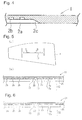
- the tear line 2 is formed of a recessed line 2a and hollows 2b arranged along the recessed line 2a at specified intervals.
- the recessed line 2a is formed by providing a raised line on the core surface of a die when the cover component 1 is formed with the die.
- the hollows 2b are bored by irradiation with a laser beam. The depth and width of the recessed line 2a and the hollows 2b and the arrangement (pitch) of the hollows 2b are appropriately determined in consideration of the material and the size of the cover component 1 and the pressure generated from the gas generator.
- the recessed line 2a is decreased in depth at the end, as shown in Fig. 4.
- the bottom near the end of the recessed line 2a forms a slope 2c about 30° to 60° inclined relative to the back of the cover component 1.
- the slope 2c is also formed with the raised line provided on the core surface of the die.
- the cover component 1 since it is only the hollows 2b that is formed by laser processing, it takes only a short time for laser processing. Since the hollows 2b have only to be formed in a uniform depth by laser processing, the output of the laser can be controlled simply by on-off control, so that it is easy to control. Accordingly, the cover component 1 is very easy to manufacture.
- the recessed line 2a is formed by molding, its depth is of high accuracy and agrees with a designed depth, and also the surface roughness of the bottom of the recessed line 2a corresponds to the raised line of the core surface, thus having a designed value.
- the cover component 1 can be surely torn open along the tear line 2 at the end.
- the cover component 1 increases in thickness gradually to absorb tearing energy gradually and stop the tearing in the region of the slope 2c at which the depth decreases gradually. Even if the tearing has overshot the endmost of the tear line 2, it stops with slight tearing from the endmost since the tearing momentum has been decreased extremely, so that the end of the tearing is near the endmost of the tear line 2.
- Fig. 5(a) is a front view of a cover component 11 according to another embodiment; and Fig. 5(b) is a cross-sectional view taken along line B-B of Fig. 5(a).
- a tear line 12 of the cover component 11 is also in H-shape having a pair of left and right vertical lines and a lateral line connecting them as is the tear line 2; however, it may be in U-shape.
- the tear line 12 is formed of the recessed line 2a and the hollows 2b arranged along the recessed line 2a at specified intervals, as is the tear line 2.
- the recessed line 2a is formed by providing a raised line on the core surface of a die when the cover component 11 is formed with the die.
- the hollows 2b are bored by irradiation with a laser beam.
- the vicinity of the middle of the length of the lateral part of the tear line 12 is lower in strength than the other part, from which the tearing of the tear line 12 starts.
- inclined parts 13 and 13 are provided in the adjacent part to a hollow 2B positioned in the vicinity of the middle, in which the recessed line 2a increases in depth at the hollow 2B.
- the inclined parts 13 and 13 are also formed with the raised line on the core surface of the die, as is the recessed line 2a.
- the ceiling surface (deepmost surface) of the hollow 2B is deeper than the ceiling surface of the other hollows 2b, thus positioned close to the front surface of the cover component 11.
- the raised line of the die core surface has a small trapezoidal salient with parts overlapping with the inclined parts 13 and 13 as a pair of oblique lines.
- a small recessed part formed with the small salient is irradiated with a laser beam at the same intensity as that for forming the hollows 2b, so that the hollow 2B deeper than the other hollows 2b is formed.
- the ceiling surface of the hollow 2B may be in the same position as those of the other hollows 2b.
- the cover component 11 with such a structure starts to be surely torn open from the vicinity of the middle of the tear line 12.
- steps 23 and 23 are provided in the adjacent part to the hollow 2B in the vicinity of the middle of a tear line 22 (neighboring parts along the length of the tear line 22) in order to start tearing.
- the steps 23 and 23 connect to the hollow 2B.
- the ceiling surface of the hollow 2B is closer to the front surface of a cover component 21 than those of the other hollows 2b; however, it may be the same.
- the other structures of the cover component 21 are the same as those of the cover component 11.
- a cover component 31 in Fig. 7 has three hollows 2B in the middle of a tear line 32 in the proximity to one another to provide low strength to start tearing.
- the size and depth of the hollows 2B are the same as those of the hollows 2b.
- the other structures of the cover component 31 are the same as those of the cover component 1.
- cover components 21 and 31 in Figs. 6 and 7 surely start to be torn open from the hollow 2B.
- FIGs. 5 and 6 although one hollow 2B in the middle has the inclined parts 13 and the steps 23, respectively, two or more hollows in the middle may have the similar inclined parts and steps. Although the steps 23 each have one step, they may be multisteps of two or more.
- the three hollows 2B are arranged in proximity in Fig. 7, two or more than four hollows may be arrange in proximity.
- Figs. 8 to 12 show other structures in which tearing start positions are made easier to be torn open than the other parts.
- Figs. 8(a) and 9(a) are cross-sectional views taken along the respective tear lines
- Figs. 8(b) and 8(c) and Figs. 9(b) and 9(c) are cross-sectional views taken along line B-B and line C-C of Figs. 8(a) and 9(a), respectively.
- Cover components 41 and 51 in Figs. 8 and 9, respectively, are the same as the above-described cover components in that respective tear lines 42 and 52 are composed of the recessed line 2a formed with a die and hollows 2b formed by laser processing.
- the tear lines 42 and 52 have the recessed line 2a deep in the part to start tearing.
- Reference numerals 43 and 53 denote deep recessed parts.
- the hollows 2b including the deep recessed part 43 have substantially the same depth.
- all the deepmost surfaces of the hollows 2b have substantially the same level. In other words, the distances between the deepmost surfaces of the hollows 2b and the front surface (the top) of the cover component 51 are substantially the same.
- the deepmost parts 43 and 53 are formed with a die, along with the recessed line 2a.
- the hollows 2b of a tear line 62 of a cover component 61 are substantially at the same level at the deepmost surfaces.
- the tear line 62 is different from the tear line 52 in that the recessed line 2a has a slightly deep part 63 and a deepmost part 64 in the middle of the slightly deep part 63 along the length of the tear line 62.
- the deep parts 63 and 64 are provided in two steps in Fig. 10, they may be in three steps or more.
- a cover component 71 in Fig. 11 is the same as the above-described cover components in that a tear line 72 is composed of the recessed line 2a and the hollows 2b.
- a deep part 73 provided in the position of the recessed line 2a to start tearing decreases in depth gradually at a deepmost part 73a in the middle of the length of the tear line 72. The tearing is started from the deepmost part 73a or from the vicinity of the hollows 2b adjacent thereto.
- the levels of the deepmost surfaces of the hollows 2b are substantially equal.
- a tear line 82 is formed of only the hollows 2b.
- the tear line 82 is formed of a recessed line 83 and the hollows 2b only at the part to start tearing.
- the hollows 2b are formed by laser processing, which are formed in column at regular intervals. The deepmost surfaces of the hollows 2b have substantially the same level.
- the part to start tearing has the hollows 2b bored from the bottom of the recessed line 83.
- the recessed line 83 is formed with a die.
- the synthetic resin for constructing the cover components examples include a styrene and/or ethylene based thermoplastic elastomer (TPE) and polypropylene.
- TPE thermoplastic elastomer
- the styrene based TPE is a compound material containing a styrene-conjugated diene block polymer and its hydrogenated block polymer as the base, to which components selected from thermoplastic resins such as an olefinic resin and a styrene resin, various rubber softeners such as a petroleum-hydrocarbon-rubber softener (oil, etc.) and a synthetic softener (polybutene, etc.), inorganic fillers, waxes, and various additives are compounded.
- thermoplastic resins such as an olefinic resin and a styrene resin
- various rubber softeners such as a petroleum-hydrocarbon-rubber softener (oil, etc.) and a synthetic
- An olefinic TPE is a compound material containing a copolymer rubber made from ethylene and C 3 to C 6 alpha olefin and a soft polymer as the base, to which components selected from various resins, softeners, inorganic fillers, waxes, various additives similar to those of the styrene TPE are compounded.
- ethylene-alpha olefin conjugated diene rubber a certain quantity of diene components such as dicyclopentadiene and ethylidene norbornane are copolymerized may be used.
- the alpha olefins that use C 3 : propylene and C 4 : butane-1 are widely on the market, which are preferable in terms of performance and cost.
- the cover components of the invention may be made from other components.
- the invention may also be applied to an instrument panel with a tear line.
- the invention can also be applied to vehicle' interior trims other than the instrument panel, such as a door trim which implements a side airbag system and a roof-side trim which implements a head-protection airbag system.
Landscapes
- Engineering & Computer Science (AREA)
- Mechanical Engineering (AREA)
- Air Bags (AREA)
Abstract
Description
Another method for forming the tear line is described in Japanese Unexamined Patent Application Publication No. 8-282420, in which a recess or a recessed line is formed by exposing a cover component to a laser beam. Fig. 8 of the gazette shows a tear line formed of an even-depth recessed line. Fig. 20 of the gazette shows a tear line having hollows at intervals in a recessed line. In the gazette, both the recessed line and the hollows in Fig. 20 are formed with a laser beam.
Claims (12)
- A cover component mounted to an airbag system and having a tear line (2; 12; 22; 32; 42; 52; 62; 72; 82) that is torn open when an airbag of the airbag system inflates, wherein
at least part of the tear line (2; 12; 22; 32; 42; 52; 62; 72; 82) includes a recessed line (2a; 83) and hollows (2b; 2B) bored in the recessed line (2a; 83) at intervals;
the recessed line (2a; 83) is formed with a raised line provided on the core surface of a die when the cover component is molded; and
the hollows (2b; 2B) are bored by laser processing. - A cover component of an airbag system according to claim 1, wherein the recessed line (2a; 83) decreases in depth gradually toward the endmost of the tear line (2; 12; 22; 32; 42; 52; 62; 72; 82) at the end of the tear line.
- A cover component of an airbag system according to claim 1 or 2, wherein the part (2B; 43; 53; 63, 64; 73; 83) of the tear line (12; 22; 32; 42; 52; 62; 72; 82) to start the tearing has a strength lower than that of the other part.
- A cover component of an airbag system according to claim 3, wherein the part (43; 53; 63, 64; 73) to start the tearing includes a recessed line (2a) and hollows (2b) and wherein the part to start the tearing is deeper than the other part.
- A cover component of an airbag system according to claim 3, wherein the part to start the tearing includes a recessed line (83) and hollows (2b) and wherein the other tear line (82) is formed of hollows (2b).
- An airbag system comprising a folded airbag, a gas generator for inflating the airbag, and a cover component covering the airbag, wherein
the cover component is a cover component according to any one of claims 1 to 5. - A vehicle interior trim having a tear line (2; 12; 22; 32; 42; 52; 62; 72; 82) that is torn open when an airbag of an airbag system inflates, wherein
at least part of the tear line (2; 12; 22; 32; 42; 52; 62; 72; 82) includes a recessed line (2a; 83) and hollows (2b; 2B) bored in the recessed line (2a; 83) at intervals;
the recessed line (2a; 83) is formed with a raised line provided on the core surface of a die when the cover component is molded; and
the hollows (2b; 2B) are bored by laser processing. - A vehicle interior trim according to claim 7, wherein the recessed line (2a; 83) decreases in depth gradually toward the endmost of the tear line (2; 12; 22; 32; 42; 52; 62; 72; 82) at the end of the tear line.
- A vehicle interior trim according to claim 7 or 8, wherein the part (2B; 43; 53; 63, 64; 73; 83) of the tear line (12; 22; 32; 42; 52; 62; 72; 82) to start the tearing has a strength lower than that of the other part.
- A vehicle interior trim according to claim 9, wherein the part (43; 53; 63, 64; 73) to start the tearing includes a recessed line (2a) and hollows (2b) and wherein the part to start the tearing is deeper than the other part.
- A vehicle interior trim according to claim 10, wherein the part to start the tearing includes a recessed line (83) and hollows (2b) and wherein the other tear line (82) is formed of hollows (2b).
- A vehicle interior trim according to any one of claims 7 to 11, wherein the vehicle interior trim is an instrument panel.
Applications Claiming Priority (4)
| Application Number | Priority Date | Filing Date | Title |
|---|---|---|---|
| JP2003110501 | 2003-04-15 | ||
| JP2003110501 | 2003-04-15 | ||
| JP2003317003 | 2003-09-09 | ||
| JP2003317003A JP2004331046A (en) | 2003-04-15 | 2003-09-09 | Cover component for airbag device, air bag device and interior member for vehicle |
Publications (2)
| Publication Number | Publication Date |
|---|---|
| EP1468878A1 true EP1468878A1 (en) | 2004-10-20 |
| EP1468878B1 EP1468878B1 (en) | 2006-09-06 |
Family
ID=32911479
Family Applications (1)
| Application Number | Title | Priority Date | Filing Date |
|---|---|---|---|
| EP04006696A Expired - Lifetime EP1468878B1 (en) | 2003-04-15 | 2004-03-19 | Method of manufacturing a cover component of airbag system, airbag system, and vehicle interior trim |
Country Status (5)
| Country | Link |
|---|---|
| US (1) | US7398991B2 (en) |
| EP (1) | EP1468878B1 (en) |
| JP (1) | JP2004331046A (en) |
| CN (1) | CN100445136C (en) |
| DE (1) | DE602004002227T2 (en) |
Cited By (8)
| Publication number | Priority date | Publication date | Assignee | Title |
|---|---|---|---|---|
| GB2426961A (en) * | 2005-06-10 | 2006-12-13 | Lear Corp | An interior panel with an air bag door and a method of production |
| DE102006003684A1 (en) * | 2006-01-24 | 2007-07-26 | Jenoptik Automatisierungstechnik Gmbh | A method of creating a frangible line in a multilayer airbag cover using a laser |
| EP1738970A3 (en) * | 2005-05-31 | 2008-03-12 | Sanko Gosei Kabushiki Kaisha | Airbag apparatus for vehicle and airbag cover |
| FR2916175A1 (en) * | 2007-05-16 | 2008-11-21 | Faurecia Interieur Ind Snc | CLOTHING ELEMENT OF THE INTERIOR OF A MOTOR VEHICLE. |
| EP2050628A4 (en) * | 2006-07-31 | 2010-04-21 | Toyota Auto Body Co Ltd | Airbag door, method of controlling breakage of tear line, and method of expanding airbag |
| WO2010049759A1 (en) | 2008-10-30 | 2010-05-06 | Faurecia Interieur Industrie | Process for manufacturing an automobile interior trim part with an airbag cover, and to the associated machine |
| FR3083760A1 (en) * | 2018-07-12 | 2020-01-17 | Reydel Automotive B.V. | PACKING PIECE FOR AIRBAG SHUTTER |
| RU2783174C2 (en) * | 2018-07-12 | 2022-11-09 | Смрк Аутомотив Холдингз Нетерлендз Б.В. | Trim element for folding cover of airbag |
Families Citing this family (31)
| Publication number | Priority date | Publication date | Assignee | Title |
|---|---|---|---|---|
| JP4195839B2 (en) * | 2003-06-30 | 2008-12-17 | タカタ株式会社 | Airbag cover, airbag module |
| JP4457822B2 (en) * | 2004-02-02 | 2010-04-28 | 豊田合成株式会社 | Airbag device for passenger seat |
| JP2005219572A (en) * | 2004-02-04 | 2005-08-18 | Sanko Gosei Ltd | Air bag device for automobile |
| JP4382518B2 (en) * | 2004-02-19 | 2009-12-16 | 三光合成株式会社 | Airbag device for automobile |
| JP4446830B2 (en) * | 2004-07-29 | 2010-04-07 | 日本プラスト株式会社 | Airbag device |
| US20090278337A1 (en) * | 2004-12-14 | 2009-11-12 | Johnson Controls Technology Company | Air bag cover |
| JP4735338B2 (en) * | 2006-03-03 | 2011-07-27 | 豊田合成株式会社 | Airbag cover |
| DE102006033895A1 (en) * | 2006-07-18 | 2008-01-31 | Takata-Petri Ag | Airbag module for a motor vehicle |
| JP4918883B2 (en) * | 2007-05-28 | 2012-04-18 | トヨタ車体株式会社 | Airbag door |
| JP4918820B2 (en) * | 2006-07-31 | 2012-04-18 | トヨタ車体株式会社 | Tearline break control method and airbag door tearline |
| JP4918821B2 (en) * | 2006-07-31 | 2012-04-18 | トヨタ車体株式会社 | Tiered structure |
| US20080315566A1 (en) * | 2007-06-20 | 2008-12-25 | Andrasik Iii Joseph | Instrument panel with integral hidden door cover and method of manufacture thereof |
| KR100886125B1 (en) * | 2007-11-01 | 2009-02-27 | 현대모비스 주식회사 | Car Instrument Panel |
| US8171836B2 (en) * | 2008-12-16 | 2012-05-08 | Automotive Components Holdings, Llc | Pre-weakened skin seam for an air bag deployment cover |
| JP5352342B2 (en) * | 2009-05-15 | 2013-11-27 | 本田技研工業株式会社 | Airbag deployment part and processing method thereof |
| US20120223512A1 (en) * | 2011-03-03 | 2012-09-06 | Faurecia Interior Systems, Inc. | Angled tear seams for airbag covers |
| JP5604353B2 (en) * | 2011-03-31 | 2014-10-08 | タカタ株式会社 | Airbag device and airbag cover |
| JP5674575B2 (en) * | 2011-07-11 | 2015-02-25 | 株式会社イノアックコーポレーション | Airbag door manufacturing method |
| DE102011112135A1 (en) * | 2011-09-01 | 2013-03-07 | Audi Ag | cowling |
| US8567815B2 (en) * | 2011-09-08 | 2013-10-29 | Faurecia Interior Systems, Inc. | Limiting energy leakage during laser scoring of vehicle airbag coverings |
| WO2014062259A1 (en) * | 2012-10-15 | 2014-04-24 | Inteva Products, Llc | Pre-weakened cover for an airbag and method of making |
| KR20140115654A (en) * | 2013-03-21 | 2014-10-01 | 현대모비스 주식회사 | the air bag of a vehicle |
| US20150028570A1 (en) * | 2013-07-24 | 2015-01-29 | Faurecia Interior System, Inc. | Airbag tear seams formed by irradiation |
| KR102095565B1 (en) * | 2013-11-01 | 2020-03-31 | 현대모비스 주식회사 | Airbag of Vehicle |
| US9771044B1 (en) * | 2016-04-25 | 2017-09-26 | Ford Global Technologies, Llc | Leather trim panel skin hidden tear seam with disrupted fiber matrix |
| GB2570456B (en) * | 2018-01-24 | 2020-06-17 | Ford Global Tech Llc | Vehicle trim panel |
| CN108263330A (en) * | 2018-03-29 | 2018-07-10 | 江铃汽车股份有限公司 | It can remove the air bag cover plate of tearing mark |
| US10878681B2 (en) | 2018-09-22 | 2020-12-29 | Fedex Corporate Services, Inc. | Systems, apparatus, and methods for detecting an environmental anomaly and initiating an enhanced automatic response using elements of a wireless node network including a command node environmental sensor |
| CN110667507A (en) * | 2019-10-31 | 2020-01-10 | 北京汽车集团越野车有限公司 | Automobile with a detachable front cover |
| CN111391777B (en) | 2020-04-23 | 2022-06-14 | 上海延锋金桥汽车饰件系统有限公司 | Skin for automotive upholstery |
| IT202000015523A1 (en) | 2020-06-26 | 2021-12-26 | Ferrari Spa | COVER PANEL FOR A VEHICLE COMPARTMENT AND PROVIDED WITH A WEAKENING FOR THE OPENING OF AN UNDERLYING AIRBAG |
Citations (5)
| Publication number | Priority date | Publication date | Assignee | Title |
|---|---|---|---|---|
| US5195773A (en) * | 1990-05-24 | 1993-03-23 | Takata Corporation | Cover for accommodating an air bag |
| US5997030A (en) * | 1997-03-19 | 1999-12-07 | Lear Automotive Dearborn, Inc. | Vehicle instrument panel with seamless airbag cover |
| JPH11334490A (en) * | 1998-05-21 | 1999-12-07 | Inoac Corporation:Kk | Vehicular interior material having air bag door part and manufacture of it |
| EP0963806A1 (en) * | 1994-10-31 | 1999-12-15 | Tip Engineering Group, Inc. | Process for preweakening an automotive trim cover for an air bag deployment opening |
| US6113131A (en) * | 1997-05-02 | 2000-09-05 | Kansei Corporation | Instrument panel |
Family Cites Families (12)
| Publication number | Priority date | Publication date | Assignee | Title |
|---|---|---|---|---|
| DE3837085A1 (en) | 1988-11-01 | 1990-05-03 | Kolbenschmidt Ag | GAS BAG IMPACT PROTECTION DEVICE |
| JP2815597B2 (en) | 1989-01-31 | 1998-10-27 | マツダ株式会社 | Car airbag structure |
| US5180187A (en) * | 1989-02-18 | 1993-01-19 | Daimler-Benz Ag | Cover for an airbag unit and the process for producing it |
| JPH0694266B2 (en) * | 1989-02-20 | 1994-11-24 | タカタ株式会社 | Airbag storage cover |
| JP2906584B2 (en) * | 1990-05-24 | 1999-06-21 | タカタ株式会社 | Airbag storage cover |
| US5152548A (en) * | 1990-05-24 | 1992-10-06 | Takata Corporation | Cover for accommodating an air bag |
| JP2539939B2 (en) * | 1990-05-24 | 1996-10-02 | タカタ 株式会社 | Cover for airbag storage |
| JP3123158B2 (en) * | 1991-12-11 | 2001-01-09 | タカタ株式会社 | Airbag storage cover |
| JP3201243B2 (en) * | 1995-12-12 | 2001-08-20 | 豊田合成株式会社 | Automotive interior parts with lid for airbag |
| JPH11170951A (en) | 1997-12-15 | 1999-06-29 | Kansei Corp | Air bag storage cover |
| US6453535B1 (en) * | 1998-06-25 | 2002-09-24 | Tip Engineering Group, Inc. | Process for manufacturing an automotive trim piece preweakened to form an air bag deployment opening |
| JP2001080442A (en) | 1999-09-13 | 2001-03-27 | Toyoda Gosei Co Ltd | Air bag cover |
-
2003
- 2003-09-09 JP JP2003317003A patent/JP2004331046A/en active Pending
-
2004
- 2004-02-03 US US10/769,920 patent/US7398991B2/en not_active Expired - Fee Related
- 2004-02-26 CN CNB2004100067934A patent/CN100445136C/en not_active Expired - Fee Related
- 2004-03-19 EP EP04006696A patent/EP1468878B1/en not_active Expired - Lifetime
- 2004-03-19 DE DE602004002227T patent/DE602004002227T2/en not_active Expired - Lifetime
Patent Citations (5)
| Publication number | Priority date | Publication date | Assignee | Title |
|---|---|---|---|---|
| US5195773A (en) * | 1990-05-24 | 1993-03-23 | Takata Corporation | Cover for accommodating an air bag |
| EP0963806A1 (en) * | 1994-10-31 | 1999-12-15 | Tip Engineering Group, Inc. | Process for preweakening an automotive trim cover for an air bag deployment opening |
| US5997030A (en) * | 1997-03-19 | 1999-12-07 | Lear Automotive Dearborn, Inc. | Vehicle instrument panel with seamless airbag cover |
| US6113131A (en) * | 1997-05-02 | 2000-09-05 | Kansei Corporation | Instrument panel |
| JPH11334490A (en) * | 1998-05-21 | 1999-12-07 | Inoac Corporation:Kk | Vehicular interior material having air bag door part and manufacture of it |
Non-Patent Citations (1)
| Title |
|---|
| PATENT ABSTRACTS OF JAPAN vol. 2000, no. 03 30 March 2000 (2000-03-30) * |
Cited By (13)
| Publication number | Priority date | Publication date | Assignee | Title |
|---|---|---|---|---|
| EP1738970A3 (en) * | 2005-05-31 | 2008-03-12 | Sanko Gosei Kabushiki Kaisha | Airbag apparatus for vehicle and airbag cover |
| GB2426961A (en) * | 2005-06-10 | 2006-12-13 | Lear Corp | An interior panel with an air bag door and a method of production |
| GB2426961B (en) * | 2005-06-10 | 2007-09-19 | Lear Corp | Interior panel part for motor vehicles and a method of manufacturing such an interior panel part |
| DE102006003684A1 (en) * | 2006-01-24 | 2007-07-26 | Jenoptik Automatisierungstechnik Gmbh | A method of creating a frangible line in a multilayer airbag cover using a laser |
| US7431328B2 (en) | 2006-01-24 | 2008-10-07 | Jenoptik Automatisierungstechnik Gmbh | Method for generating a predetermined break line in a multilayer airbag cover using a laser |
| EP2050628A4 (en) * | 2006-07-31 | 2010-04-21 | Toyota Auto Body Co Ltd | Airbag door, method of controlling breakage of tear line, and method of expanding airbag |
| WO2008142309A1 (en) * | 2007-05-16 | 2008-11-27 | Faurecia Interieur Industrie | Fitting member for the inside of an automobile |
| FR2916175A1 (en) * | 2007-05-16 | 2008-11-21 | Faurecia Interieur Ind Snc | CLOTHING ELEMENT OF THE INTERIOR OF A MOTOR VEHICLE. |
| CN101541596B (en) * | 2007-05-16 | 2011-11-16 | 佛吉亚汽车内部设备工业公司 | Fitting member for the inside of an automobile |
| US8342568B2 (en) | 2007-05-16 | 2013-01-01 | Faurecia Interieur Industrie | Covering element for the interior of a motor vehicle |
| WO2010049759A1 (en) | 2008-10-30 | 2010-05-06 | Faurecia Interieur Industrie | Process for manufacturing an automobile interior trim part with an airbag cover, and to the associated machine |
| FR3083760A1 (en) * | 2018-07-12 | 2020-01-17 | Reydel Automotive B.V. | PACKING PIECE FOR AIRBAG SHUTTER |
| RU2783174C2 (en) * | 2018-07-12 | 2022-11-09 | Смрк Аутомотив Холдингз Нетерлендз Б.В. | Trim element for folding cover of airbag |
Also Published As
| Publication number | Publication date |
|---|---|
| DE602004002227T2 (en) | 2007-09-06 |
| JP2004331046A (en) | 2004-11-25 |
| CN1621276A (en) | 2005-06-01 |
| US20040207181A1 (en) | 2004-10-21 |
| CN100445136C (en) | 2008-12-24 |
| US7398991B2 (en) | 2008-07-15 |
| EP1468878B1 (en) | 2006-09-06 |
| DE602004002227D1 (en) | 2006-10-19 |
Similar Documents
| Publication | Publication Date | Title |
|---|---|---|
| EP1468878B1 (en) | Method of manufacturing a cover component of airbag system, airbag system, and vehicle interior trim | |
| KR100232759B1 (en) | Gas bag cover for vehicle occupant restraint and its manufacturing method | |
| US7607681B2 (en) | Airbag cover | |
| US7000942B2 (en) | Method for introducing a line of weakening with low tearing resistance into an airbag cover and airbag cover produced by this method | |
| US20030020202A1 (en) | Method for manufacturing automobile interior article | |
| US7810836B2 (en) | Invisible airbag cover having a tear line | |
| US8557375B2 (en) | Thermoplastic film for airbag covers | |
| CN210212318U (en) | Airbag system for a vehicle and a trim component | |
| CN103402827A (en) | Angled tear seams for airbag covers | |
| US20010045728A1 (en) | Dashboard | |
| CN106143390B (en) | Vehicle interior panel for covering airbag and method for manufacturing same | |
| US7604251B2 (en) | Airbag module | |
| ATE410343T1 (en) | INTERIOR TRIM PART FOR MOTOR VEHICLES | |
| EP1713664B1 (en) | Method of making an air-bag and an air-bag | |
| US20020190505A1 (en) | Airbag covering provided with a specified rupture line and method for the production thereof | |
| JP3370044B2 (en) | Skin, manufacturing method thereof, manufacturing method of airbag door skin, and airbag door structure | |
| US7213832B2 (en) | Airbag module and module cover | |
| US9713997B2 (en) | Interior panels including substrates with film inserts for defining integrated airbag deployment doors for motor vehicles and methods of making the same | |
| US10369953B2 (en) | Interior panels including substrates with inserts for defining integrated airbag deployment doors for motor vehicles and methods of making the same | |
| US20060082109A1 (en) | Method of making an automotive trim assembly having an integrated airbag door | |
| US7128334B2 (en) | Ultrasonic blade design for scoring double angle groove and products therefrom | |
| JP4215612B2 (en) | Automotive interior panels | |
| CN101384456A (en) | Vehicle dashboard with hidden airbag door and integrated airbag slide | |
| JP2007083762A (en) | Headliner terminal structure and headliner interior material | |
| US20010027628A1 (en) | Decorative member material |
Legal Events
| Date | Code | Title | Description |
|---|---|---|---|
| PUAI | Public reference made under article 153(3) epc to a published international application that has entered the european phase |
Free format text: ORIGINAL CODE: 0009012 |
|
| AK | Designated contracting states |
Kind code of ref document: A1 Designated state(s): AT BE BG CH CY CZ DE DK EE ES FI FR GB GR HU IE IT LI LU MC NL PL PT RO SE SI SK TR |
|
| AX | Request for extension of the european patent |
Extension state: AL LT LV MK |
|
| 17P | Request for examination filed |
Effective date: 20050418 |
|
| AKX | Designation fees paid |
Designated state(s): DE FR GB SE |
|
| 17Q | First examination report despatched |
Effective date: 20050706 |
|
| GRAP | Despatch of communication of intention to grant a patent |
Free format text: ORIGINAL CODE: EPIDOSNIGR1 |
|
| RTI1 | Title (correction) |
Free format text: METHOD OF MANUFACTURING A COVER COMPONENT OF AIRBAG SYSTEM, AIRBAG SYSTEM, AND VEHICLE INTERIOR TRIM |
|
| GRAS | Grant fee paid |
Free format text: ORIGINAL CODE: EPIDOSNIGR3 |
|
| GRAA | (expected) grant |
Free format text: ORIGINAL CODE: 0009210 |
|
| AK | Designated contracting states |
Kind code of ref document: B1 Designated state(s): DE FR GB SE |
|
| REG | Reference to a national code |
Ref country code: GB Ref legal event code: FG4D |
|
| REF | Corresponds to: |
Ref document number: 602004002227 Country of ref document: DE Date of ref document: 20061019 Kind code of ref document: P |
|
| REG | Reference to a national code |
Ref country code: SE Ref legal event code: TRGR |
|
| ET | Fr: translation filed | ||
| PLBE | No opposition filed within time limit |
Free format text: ORIGINAL CODE: 0009261 |
|
| STAA | Information on the status of an ep patent application or granted ep patent |
Free format text: STATUS: NO OPPOSITION FILED WITHIN TIME LIMIT |
|
| 26N | No opposition filed |
Effective date: 20070607 |
|
| PGFP | Annual fee paid to national office [announced via postgrant information from national office to epo] |
Ref country code: SE Payment date: 20080306 Year of fee payment: 5 |
|
| PGFP | Annual fee paid to national office [announced via postgrant information from national office to epo] |
Ref country code: FR Payment date: 20080311 Year of fee payment: 5 |
|
| EUG | Se: european patent has lapsed | ||
| REG | Reference to a national code |
Ref country code: FR Ref legal event code: ST Effective date: 20091130 |
|
| PG25 | Lapsed in a contracting state [announced via postgrant information from national office to epo] |
Ref country code: FR Free format text: LAPSE BECAUSE OF NON-PAYMENT OF DUE FEES Effective date: 20091123 |
|
| PG25 | Lapsed in a contracting state [announced via postgrant information from national office to epo] |
Ref country code: SE Free format text: LAPSE BECAUSE OF NON-PAYMENT OF DUE FEES Effective date: 20090320 |
|
| PGFP | Annual fee paid to national office [announced via postgrant information from national office to epo] |
Ref country code: GB Payment date: 20130313 Year of fee payment: 10 |
|
| GBPC | Gb: european patent ceased through non-payment of renewal fee |
Effective date: 20140319 |
|
| PG25 | Lapsed in a contracting state [announced via postgrant information from national office to epo] |
Ref country code: GB Free format text: LAPSE BECAUSE OF NON-PAYMENT OF DUE FEES Effective date: 20140319 |
|
| REG | Reference to a national code |
Ref country code: DE Ref legal event code: R082 Ref document number: 602004002227 Country of ref document: DE Representative=s name: KRAUS & WEISERT PATENTANWAELTE PARTGMBB, DE Ref country code: DE Ref legal event code: R081 Ref document number: 602004002227 Country of ref document: DE Owner name: JOYSON SAFETY SYSTEMS JAPAN K.K., JP Free format text: FORMER OWNER: TAKATA CORP., TOKIO/TOKYO, JP |
|
| PGFP | Annual fee paid to national office [announced via postgrant information from national office to epo] |
Ref country code: DE Payment date: 20180322 Year of fee payment: 15 |
|
| REG | Reference to a national code |
Ref country code: DE Ref legal event code: R119 Ref document number: 602004002227 Country of ref document: DE |
|
| PG25 | Lapsed in a contracting state [announced via postgrant information from national office to epo] |
Ref country code: DE Free format text: LAPSE BECAUSE OF NON-PAYMENT OF DUE FEES Effective date: 20191001 |