EP1468849B1 - Air distribution assembly for vehicles - Google Patents
Air distribution assembly for vehicles Download PDFInfo
- Publication number
- EP1468849B1 EP1468849B1 EP03425244A EP03425244A EP1468849B1 EP 1468849 B1 EP1468849 B1 EP 1468849B1 EP 03425244 A EP03425244 A EP 03425244A EP 03425244 A EP03425244 A EP 03425244A EP 1468849 B1 EP1468849 B1 EP 1468849B1
- Authority
- EP
- European Patent Office
- Prior art keywords
- shutter
- connecting element
- opening
- distribution assembly
- axis
- Prior art date
- Legal status (The legal status is an assumption and is not a legal conclusion. Google has not performed a legal analysis and makes no representation as to the accuracy of the status listed.)
- Expired - Lifetime
Links
Images



Classifications
-
- B—PERFORMING OPERATIONS; TRANSPORTING
- B60—VEHICLES IN GENERAL
- B60H—ARRANGEMENTS OF HEATING, COOLING, VENTILATING OR OTHER AIR-TREATING DEVICES SPECIALLY ADAPTED FOR PASSENGER OR GOODS SPACES OF VEHICLES
- B60H1/00—Heating, cooling or ventilating devices
- B60H1/00642—Control systems or circuits; Control members or indication devices for heating, cooling or ventilating devices
- B60H1/00664—Construction or arrangement of damper doors
- B60H1/00671—Damper doors moved by rotation; Grilles
Definitions
- the present invention relates to an air distribution assembly for vehicles according to the preamble of the main claim.
- Air distribution assemblies for vehicles which comprise a stationary case provided with at least a first and a second opening for the passage of respective air flows and a first and a second shutters articulated to the case about respective axes and associated to the first and to the second opening.
- the present invention specifically relates to an air distribution assembly in which the first and the second shutters are mutually connected by means of a connecting element.
- the connecting element between the two shutters causes the motion of a first shutter (driving shutter) causes a corresponding motion of the second shutter (driven shutter).
- the main drawback of the prior art solutions is constituted by the fact that the range of motion of the driving shutter is limited by the maximum travel of the driven shutter.
- GB-A-613022 discloses an apparatus for distributing hot air in vehicles comprising a rectangular casing having an air inlet and air outlets controlled by a first valve connected with a second valve by an arm with a variable length.
- EP-A-0 648 626 discloses an air distribution assembly according to the preamble of claim 1.
- the present invention aims to provide an air distribution assembly having the characteristics constituting the subject of the main claim.
- the number 10 designates a stationary case of an air distribution assembly for vehicles.
- the case 10 comprises a front wall 12 and a lateral wall 14 which define a distribution chamber 16.
- the case 14 is provided with a first opening 18 and with a second opening 20.
- the first opening 18 is formed on the lateral wall 14 whilst the second opening 20 is formed in the front wall 12.
- Said openings are thus substantially arranged at 90° from each other.
- the openings 18 and 20 are shown positioned in the same plane.
- the case 14 has a separating element 22 which subdivides the first opening 18 in two parts.
- a first part of the opening 18 is connected to a first distribution conduit 24 and a second part of the opening 18 is connected to a second distribution conduit 26.
- the opening 20 is connected to a third distribution conduit 28.
- the opening 18 and 20 put in communication the distribution chamber 26 with the distribution conduits 24, 26 and 28.
- the case 10 bears two movable shutters 30, 32 able to control the opening and the closing of the openings 18, 20.
- the first shutter 30 is associated to the opening 18 and is mounted capable of rotating with respect to the case 10 about an axis 34 orthogonal to the front wall 12.
- the second shutter 32 is associated to the opening 20 and is mounted able to rotate about a second axis 36 orthogonal to the first axis 34 and contained in the plane of the front wall 12.
- the first shutter 30 has, in a front view, substantially the shape of a triangle and is hinged about the axis 34 in correspondence with a vertex of said triangle.
- the second shutter 32 instead has substantially the shape of a butterfly valve formed by a rectangular panel articulated about the axis 36 in correspondence with its own central axis of symmetry.
- the connecting element 38 comprises two parts 40, 42 able to slide relative to one another along a common rectilinear direction coinciding with the axis 44.
- Each of the two parts 40, 42 is provided with a longitudinal guide slit 46 engaged by an engagement organ 48 borne by the other part, in such a way as to obtain a telescoping structure.
- a helical compression spring 50 is positioned coaxially to the axis 44 between the two parts 40, 42. The spring 50 tends to maintain the two parts 40, 42 in the resting position shown in Figure 7 and 8.
- the spring is compressed when the two parts 40, 42 are moved away from each other in the direction indicated by the arrows 52 in Figure 9.
- the spring 50 brings the connecting element 38 to the original resting position when the force that tends to move the two parts 40, 42 away from each other ceases.
- the spring 50 could be replaced by flexible elastic profiles obtained in integral form with the two parts 40, 42.
- Each of the two parts 40, 42 is provided with a spherical head 54.
- Each of the two parts 40, 42 also has a guiding pin 54 that engages in sliding fashion a hole 56 obtained in the other part.
- the two spherical heads 54 of the connecting element 38 engage respective spherical seats 58, 60.
- the spherical seat 60 is formed at the end of a rod 62 obtained in integral form with the shutter 30.
- the spherical seat 58 is obtained directly on the wall of the shutter 32.
- the spherical seats 58, 60 define the articulation points of the ends of the connecting element 38 to the shutters 30, 32. Both seats 58, 60 are offset relative to the articulation axes 34, 36 of the shutters 30, 32.
- the operation of the distribution assembly according to the present invention shall now be described with reference to Figures 4, 5 and 6.
- the shutter 30 is connected to a control device which allows to select the position of the shutter 30 about the axis 34.
- the first shutter 30 determines, by means of the connecting element 38, the position of the second shutter 32 about the axis 36. In the position shown in Figure 4, the first shutter 30 closes the opening 18.
- the connecting element 38 is in the resting position and the shutter 32 is in the open position.
- the flow of air present in the distribution chamber 16 is thus conveyed into the conduit 28 as indicated by the arrow 64 in Figure 4.
- the opening 20 is closed by the second shutter 32.
- the conduit 26 is thus closed whilst the conduit 24 is in communication with the distribution chamber 26.
- the air flow present in the distribution chamber 26 thus exits through the conduit 24 as shown by the arrow 66 in Figure 5.
- the connecting element 38 is also in the resting position.
- connecting element 38 has a fixed length
- the distribution assembly could assume only the positions shown in Figures 4 and 5.
- the fact of using a connecting element 38 with variable length allows to increase considerably the travel of the driving shutter 30 and to increase the possibility of distributing the air flow.
Landscapes
- Physics & Mathematics (AREA)
- Thermal Sciences (AREA)
- Engineering & Computer Science (AREA)
- Mechanical Engineering (AREA)
- Air-Flow Control Members (AREA)
- Multiple-Way Valves (AREA)
- Ignition Installations For Internal Combustion Engines (AREA)
- Exhaust Gas After Treatment (AREA)
- Air-Conditioning For Vehicles (AREA)
Abstract
Description
- The present invention relates to an air distribution assembly for vehicles according to the preamble of the main claim.
- Air distribution assemblies for vehicles are already known which comprise a stationary case provided with at least a first and a second opening for the passage of respective air flows and a first and a second shutters articulated to the case about respective axes and associated to the first and to the second opening.
- The present invention specifically relates to an air distribution assembly in which the first and the second shutters are mutually connected by means of a connecting element. In distribution assemblies of this kind, the movements of the two shutters are not independent. The connecting element between the two shutters causes the motion of a first shutter (driving shutter) causes a corresponding motion of the second shutter (driven shutter).
- The main drawback of the prior art solutions is constituted by the fact that the range of motion of the driving shutter is limited by the maximum travel of the driven shutter.
- GB-A-613022 discloses an apparatus for distributing hot air in vehicles comprising a rectangular casing having an air inlet and air outlets controlled by a first valve connected with a second valve by an arm with a variable length. EP-A-0 648 626 discloses an air distribution assembly according to the preamble of claim 1.
- The present invention aims to provide an air distribution assembly having the characteristics constituting the subject of the main claim.
- The present invention shall now be described in detail with reference to the accompanying drawings, provided purely by way of non limiting example, in which:
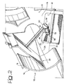
- Figures 1, 2 and 3 are schematic perspective views illustrating an air distribution assembly according to the present invention in three different operative positions,
- Figures 4, 5 and 6 are schematic views showing the distribution assembly in the operative positions corresponding, respectively, to Figures 1, 2 and 3,
- Figure 7 is a lateral view of the connecting element indicated by the arrow VII in Figure 1,
- Figure 8 is a section according to the line VIII-VIII of Figure 7, and
- Figure 9 is a similar section to Figure 8, showing the connecting element in an extended position.
- With reference to Figures 1 through 3, the
number 10 designates a stationary case of an air distribution assembly for vehicles. Thecase 10 comprises afront wall 12 and alateral wall 14 which define adistribution chamber 16. - With reference in particular to Figures 4 through 6, the
case 14 is provided with afirst opening 18 and with asecond opening 20. In a practical embodiment shown in Figures 1 through 3, thefirst opening 18 is formed on thelateral wall 14 whilst thesecond opening 20 is formed in thefront wall 12. - Said openings are thus substantially arranged at 90° from each other. In Figures 4, 5 and 6 for greater ease of representation and to simplify comprehension, the
openings - The
case 14 has a separatingelement 22 which subdivides the first opening 18 in two parts. - A first part of the opening 18 is connected to a
first distribution conduit 24 and a second part of the opening 18 is connected to asecond distribution conduit 26. - The opening 20 is connected to a
third distribution conduit 28. The opening 18 and 20 put in communication thedistribution chamber 26 with thedistribution conduits - With reference to Figures 1 through 6, the
case 10 bears twomovable shutters openings first shutter 30 is associated to the opening 18 and is mounted capable of rotating with respect to thecase 10 about anaxis 34 orthogonal to thefront wall 12. Thesecond shutter 32 is associated to theopening 20 and is mounted able to rotate about asecond axis 36 orthogonal to thefirst axis 34 and contained in the plane of thefront wall 12. - The
first shutter 30 has, in a front view, substantially the shape of a triangle and is hinged about theaxis 34 in correspondence with a vertex of said triangle. Thesecond shutter 32 instead has substantially the shape of a butterfly valve formed by a rectangular panel articulated about theaxis 36 in correspondence with its own central axis of symmetry. - The two
shutters element 38 of variable length. With reference to Figures 7 through 9, in an embodiment of the present invention theconnecting element 38 comprises twoparts axis 44. Each of the twoparts longitudinal guide slit 46 engaged by anengagement organ 48 borne by the other part, in such a way as to obtain a telescoping structure. Ahelical compression spring 50 is positioned coaxially to theaxis 44 between the twoparts spring 50 tends to maintain the twoparts parts arrows 52 in Figure 9. Thespring 50 brings the connectingelement 38 to the original resting position when the force that tends to move the twoparts spring 50 could be replaced by flexible elastic profiles obtained in integral form with the twoparts parts spherical head 54. Each of the twoparts pin 54 that engages in sliding fashion ahole 56 obtained in the other part. - With reference to Figures 1 through 3, the two
spherical heads 54 of the connectingelement 38 engage respectivespherical seats spherical seat 60 is formed at the end of arod 62 obtained in integral form with theshutter 30. Thespherical seat 58 is obtained directly on the wall of theshutter 32. Thespherical seats element 38 to theshutters seats articulation axes shutters - The operation of the distribution assembly according to the present invention shall now be described with reference to Figures 4, 5 and 6. The
shutter 30 is connected to a control device which allows to select the position of theshutter 30 about theaxis 34. Thefirst shutter 30 determines, by means of the connectingelement 38, the position of thesecond shutter 32 about theaxis 36. In the position shown in Figure 4, thefirst shutter 30 closes theopening 18. The connectingelement 38 is in the resting position and theshutter 32 is in the open position. The flow of air present in thedistribution chamber 16 is thus conveyed into theconduit 28 as indicated by thearrow 64 in Figure 4. - Starting from the position of Figure 4, causing the rotation of the
first shutter 30 counter-clockwise, the position shown in Figure 5 is reached. In this position, thefirst shutter 30 opens a first half of the opening 18 and closes the second half of the second opening 18. The rotation of theshutter 30 determines, through the connectingelement 38, a rotation of thesecond shutter 32 about theaxis 36. - In the configuration shown in Figure 5, the
opening 20 is closed by thesecond shutter 32. Theconduit 26 is thus closed whilst theconduit 24 is in communication with thedistribution chamber 26. The air flow present in thedistribution chamber 26 thus exits through theconduit 24 as shown by thearrow 66 in Figure 5. In the position shown in Figure 5, the connectingelement 38 is also in the resting position. - Continuing to rotate the
first shutter 30 in counter-clockwise direction, the position shown in Figure 6 is reached. During this additional rotation, thesecond shutter 32 remains stationary. The connectingelement 38 extends telescopically allowing the further rotation of thefirst shutter 30. In the configuration of Figure 6 thefirst opening 20 is closed and thesecond opening 18 is completely open and places both conduits 24, 26 in fluid communication with thedistribution chamber 16. The air flow present in thedistribution chamber 16 is divided between theconduits arrows - If the connecting
element 38 has a fixed length, the distribution assembly could assume only the positions shown in Figures 4 and 5. The fact of using a connectingelement 38 with variable length allows to increase considerably the travel of thedriving shutter 30 and to increase the possibility of distributing the air flow.
Claims (5)
- Air distribution assembly for vehicles, comprising:- a stationary case (10) provided with at least a first and a second opening (18, 20) for the passage of the respective air flows,- a first shutter (30) articulated to the case (10) about a first axis (34) and associated to the first opening (18),- a second shutter (32) articulated to the case (10) about a second axis (36) and associated to the second opening (20), the first and the second shutter (30, 32) being articulated to the case about axes (34, 36) which are substantially orthogonal to each other- a connecting element (38) operatively interposed between the first and the second shutter (30, 32) and articulated with one end to the first shutter (30) and with the other to the second shutter (32),characterised in that said connecting element (38) has a variable length in operation, and that the ends of said connecting element (38) are articulated to the first and to the second shutter (30, 32) by spherical hinges.
- Distribution assembly as claimed in claim 1 characterised in that said connecting element (38) comprises elastic means (50) tending to maintain the connecting element (38) in a resting position.
- Distribution assembly as claimed in claim 2, characterised in that said connecting element (38) comprises a first and a second part (40, 42) able to slide telescopically with respect to each other.
- Distribution assembly as claimed in claim 2, characterised in that said eleastic means comprises a helical spring (50) in compression positioned between the two parts (40, 42) of the connecting element (38).
- Distribution assembly as claimed in claim 1, characterised in that said first opening (18) is associated to at least two distribution conduits (24, 26).
Priority Applications (4)
| Application Number | Priority Date | Filing Date | Title |
|---|---|---|---|
| EP03425244A EP1468849B1 (en) | 2003-04-18 | 2003-04-18 | Air distribution assembly for vehicles |
| DE60306749T DE60306749T2 (en) | 2003-04-18 | 2003-04-18 | Distributor for ventilation air for vehicles |
| AT03425244T ATE332817T1 (en) | 2003-04-18 | 2003-04-18 | DISTRIBUTOR FOR VENTILATION AIR FOR VEHICLES |
| ES03425244T ES2268318T3 (en) | 2003-04-18 | 2003-04-18 | AIR DISTRIBUTION ASSEMBLY FOR VEHICLES. |
Applications Claiming Priority (1)
| Application Number | Priority Date | Filing Date | Title |
|---|---|---|---|
| EP03425244A EP1468849B1 (en) | 2003-04-18 | 2003-04-18 | Air distribution assembly for vehicles |
Publications (2)
| Publication Number | Publication Date |
|---|---|
| EP1468849A1 EP1468849A1 (en) | 2004-10-20 |
| EP1468849B1 true EP1468849B1 (en) | 2006-07-12 |
Family
ID=32893037
Family Applications (1)
| Application Number | Title | Priority Date | Filing Date |
|---|---|---|---|
| EP03425244A Expired - Lifetime EP1468849B1 (en) | 2003-04-18 | 2003-04-18 | Air distribution assembly for vehicles |
Country Status (4)
| Country | Link |
|---|---|
| EP (1) | EP1468849B1 (en) |
| AT (1) | ATE332817T1 (en) |
| DE (1) | DE60306749T2 (en) |
| ES (1) | ES2268318T3 (en) |
Families Citing this family (2)
| Publication number | Priority date | Publication date | Assignee | Title |
|---|---|---|---|---|
| FR2933036B1 (en) * | 2008-06-25 | 2010-09-10 | Valeo Systemes Thermiques | DEVICE FOR MANEUVERING AN AIR SHUTTING MEANS FOR A HEATING, VENTILATION AND / OR AIR CONDITIONING INSTALLATION, IN PARTICULAR A VEHICLE HABITACLE |
| JP6444678B2 (en) * | 2014-09-25 | 2018-12-26 | 株式会社ケーヒン | Air conditioner for vehicles |
Family Cites Families (3)
| Publication number | Priority date | Publication date | Assignee | Title |
|---|---|---|---|---|
| US1919625A (en) * | 1930-11-01 | 1933-07-25 | John J Nesbitt Inc | Automatic fire protection damper |
| GB613022A (en) * | 1945-07-16 | 1948-11-22 | Smith & Sons Ltd S | Improvements in or relating to apparatus for distributing hot air in vehicles |
| DE4334862A1 (en) * | 1993-10-13 | 1995-04-20 | Behr Gmbh & Co | Coupling device for a flap arrangement |
-
2003
- 2003-04-18 DE DE60306749T patent/DE60306749T2/en not_active Expired - Lifetime
- 2003-04-18 EP EP03425244A patent/EP1468849B1/en not_active Expired - Lifetime
- 2003-04-18 AT AT03425244T patent/ATE332817T1/en not_active IP Right Cessation
- 2003-04-18 ES ES03425244T patent/ES2268318T3/en not_active Expired - Lifetime
Also Published As
| Publication number | Publication date |
|---|---|
| ATE332817T1 (en) | 2006-08-15 |
| ES2268318T3 (en) | 2007-03-16 |
| EP1468849A1 (en) | 2004-10-20 |
| DE60306749D1 (en) | 2006-08-24 |
| DE60306749T2 (en) | 2007-07-12 |
Similar Documents
| Publication | Publication Date | Title |
|---|---|---|
| US11987116B2 (en) | Sequential switching of venetian blinds | |
| CN106660432B (en) | Air Nozzle Equipment for Vehicles | |
| KR20200043143A (en) | air vent for car | |
| DE19943822A1 (en) | Outflow grill for a vehicle ventilation or air conditioning system has air guide flaps which combine the functions of guide ribs and air flow opening and closing without using a closing flap | |
| US20130252538A1 (en) | Cooler blind | |
| KR101684192B1 (en) | Air vent for vehicle | |
| US12485744B2 (en) | Air guidance control unit for a motor vehicle | |
| CN111703275A (en) | Exhaust | |
| US6146265A (en) | Vehicle air outlet assembly | |
| CN113386552A (en) | Valve device with toggle coupling | |
| WO2023035813A1 (en) | Air outlet device and in-vehicle air output system | |
| KR20170137643A (en) | Damper | |
| WO2024022143A1 (en) | Air outlet device and vehicle comprising same | |
| US6126537A (en) | Blower unit for air conditioning system for automotive vehicles | |
| CN106166935A (en) | It is particularly useful for the outlet device of motor vehicles | |
| EP1468849A1 (en) | Air distribution assembly for vehicles | |
| EP3665023B1 (en) | Air ventilator for an automobile | |
| CN111559227B (en) | Hidden air outlet device for automobile | |
| CN109955678B (en) | Air-conditioning outlet airflow adjusting mechanism | |
| JP3239519B2 (en) | Vehicle air conditioner | |
| EP0972137B1 (en) | Control system for an oscillation cylinder | |
| CN101163601A (en) | Buse d'aeration pour vehicule automobile destinee a etre placee en sortie d'un conduit d'aeration debouchant dans l'habitacle du vehicule, et vehicule correspondant | |
| DE10201462B4 (en) | lever mechanism | |
| KR102628116B1 (en) | Airflap apparatus for vehicle | |
| CN113212116B (en) | Linkage control air outlet |
Legal Events
| Date | Code | Title | Description |
|---|---|---|---|
| PUAI | Public reference made under article 153(3) epc to a published international application that has entered the european phase |
Free format text: ORIGINAL CODE: 0009012 |
|
| AK | Designated contracting states |
Kind code of ref document: A1 Designated state(s): AT BE BG CH CY CZ DE DK EE ES FI FR GB GR HU IE IT LI LU MC NL PT RO SE SI SK TR |
|
| AX | Request for extension of the european patent |
Extension state: AL LT LV MK |
|
| 17P | Request for examination filed |
Effective date: 20041001 |
|
| AKX | Designation fees paid |
Designated state(s): AT BE BG CH CY CZ DE DK EE ES FI FR GB GR HU IE IT LI LU MC NL PT RO SE SI SK TR |
|
| GRAP | Despatch of communication of intention to grant a patent |
Free format text: ORIGINAL CODE: EPIDOSNIGR1 |
|
| GRAS | Grant fee paid |
Free format text: ORIGINAL CODE: EPIDOSNIGR3 |
|
| GRAA | (expected) grant |
Free format text: ORIGINAL CODE: 0009210 |
|
| AK | Designated contracting states |
Kind code of ref document: B1 Designated state(s): AT BE BG CH CY CZ DE DK EE ES FI FR GB GR HU IE IT LI LU MC NL PT RO SE SI SK TR |
|
| PG25 | Lapsed in a contracting state [announced via postgrant information from national office to epo] |
Ref country code: BE Free format text: LAPSE BECAUSE OF FAILURE TO SUBMIT A TRANSLATION OF THE DESCRIPTION OR TO PAY THE FEE WITHIN THE PRESCRIBED TIME-LIMIT Effective date: 20060712 Ref country code: AT Free format text: LAPSE BECAUSE OF FAILURE TO SUBMIT A TRANSLATION OF THE DESCRIPTION OR TO PAY THE FEE WITHIN THE PRESCRIBED TIME-LIMIT Effective date: 20060712 Ref country code: CZ Free format text: LAPSE BECAUSE OF FAILURE TO SUBMIT A TRANSLATION OF THE DESCRIPTION OR TO PAY THE FEE WITHIN THE PRESCRIBED TIME-LIMIT Effective date: 20060712 Ref country code: SI Free format text: LAPSE BECAUSE OF FAILURE TO SUBMIT A TRANSLATION OF THE DESCRIPTION OR TO PAY THE FEE WITHIN THE PRESCRIBED TIME-LIMIT Effective date: 20060712 Ref country code: FI Free format text: LAPSE BECAUSE OF FAILURE TO SUBMIT A TRANSLATION OF THE DESCRIPTION OR TO PAY THE FEE WITHIN THE PRESCRIBED TIME-LIMIT Effective date: 20060712 Ref country code: LI Free format text: LAPSE BECAUSE OF FAILURE TO SUBMIT A TRANSLATION OF THE DESCRIPTION OR TO PAY THE FEE WITHIN THE PRESCRIBED TIME-LIMIT Effective date: 20060712 Ref country code: NL Free format text: LAPSE BECAUSE OF FAILURE TO SUBMIT A TRANSLATION OF THE DESCRIPTION OR TO PAY THE FEE WITHIN THE PRESCRIBED TIME-LIMIT Effective date: 20060712 Ref country code: CH Free format text: LAPSE BECAUSE OF FAILURE TO SUBMIT A TRANSLATION OF THE DESCRIPTION OR TO PAY THE FEE WITHIN THE PRESCRIBED TIME-LIMIT Effective date: 20060712 Ref country code: SK Free format text: LAPSE BECAUSE OF FAILURE TO SUBMIT A TRANSLATION OF THE DESCRIPTION OR TO PAY THE FEE WITHIN THE PRESCRIBED TIME-LIMIT Effective date: 20060712 Ref country code: RO Free format text: LAPSE BECAUSE OF FAILURE TO SUBMIT A TRANSLATION OF THE DESCRIPTION OR TO PAY THE FEE WITHIN THE PRESCRIBED TIME-LIMIT Effective date: 20060712 Ref country code: IT Free format text: LAPSE BECAUSE OF FAILURE TO SUBMIT A TRANSLATION OF THE DESCRIPTION OR TO PAY THE FEE WITHIN THE PRESCRIBED TIME-LIMIT;WARNING: LAPSES OF ITALIAN PATENTS WITH EFFECTIVE DATE BEFORE 2007 MAY HAVE OCCURRED AT ANY TIME BEFORE 2007. THE CORRECT EFFECTIVE DATE MAY BE DIFFERENT FROM THE ONE RECORDED. Effective date: 20060712 |
|
| REG | Reference to a national code |
Ref country code: GB Ref legal event code: FG4D |
|
| REG | Reference to a national code |
Ref country code: CH Ref legal event code: EP |
|
| REG | Reference to a national code |
Ref country code: IE Ref legal event code: FG4D |
|
| REF | Corresponds to: |
Ref document number: 60306749 Country of ref document: DE Date of ref document: 20060824 Kind code of ref document: P |
|
| PG25 | Lapsed in a contracting state [announced via postgrant information from national office to epo] |
Ref country code: DK Free format text: LAPSE BECAUSE OF FAILURE TO SUBMIT A TRANSLATION OF THE DESCRIPTION OR TO PAY THE FEE WITHIN THE PRESCRIBED TIME-LIMIT Effective date: 20061012 Ref country code: BG Free format text: LAPSE BECAUSE OF FAILURE TO SUBMIT A TRANSLATION OF THE DESCRIPTION OR TO PAY THE FEE WITHIN THE PRESCRIBED TIME-LIMIT Effective date: 20061012 |
|
| REG | Reference to a national code |
Ref country code: SE Ref legal event code: TRGR |
|
| PG25 | Lapsed in a contracting state [announced via postgrant information from national office to epo] |
Ref country code: PT Free format text: LAPSE BECAUSE OF FAILURE TO SUBMIT A TRANSLATION OF THE DESCRIPTION OR TO PAY THE FEE WITHIN THE PRESCRIBED TIME-LIMIT Effective date: 20061212 |
|
| NLV1 | Nl: lapsed or annulled due to failure to fulfill the requirements of art. 29p and 29m of the patents act | ||
| ET | Fr: translation filed | ||
| REG | Reference to a national code |
Ref country code: ES Ref legal event code: FG2A Ref document number: 2268318 Country of ref document: ES Kind code of ref document: T3 |
|
| PLBE | No opposition filed within time limit |
Free format text: ORIGINAL CODE: 0009261 |
|
| STAA | Information on the status of an ep patent application or granted ep patent |
Free format text: STATUS: NO OPPOSITION FILED WITHIN TIME LIMIT |
|
| 26N | No opposition filed |
Effective date: 20070413 |
|
| PG25 | Lapsed in a contracting state [announced via postgrant information from national office to epo] |
Ref country code: GR Free format text: LAPSE BECAUSE OF FAILURE TO SUBMIT A TRANSLATION OF THE DESCRIPTION OR TO PAY THE FEE WITHIN THE PRESCRIBED TIME-LIMIT Effective date: 20061013 |
|
| PG25 | Lapsed in a contracting state [announced via postgrant information from national office to epo] |
Ref country code: IE Free format text: LAPSE BECAUSE OF NON-PAYMENT OF DUE FEES Effective date: 20070418 |
|
| PG25 | Lapsed in a contracting state [announced via postgrant information from national office to epo] |
Ref country code: EE Free format text: LAPSE BECAUSE OF FAILURE TO SUBMIT A TRANSLATION OF THE DESCRIPTION OR TO PAY THE FEE WITHIN THE PRESCRIBED TIME-LIMIT Effective date: 20060712 |
|
| PG25 | Lapsed in a contracting state [announced via postgrant information from national office to epo] |
Ref country code: MC Free format text: LAPSE BECAUSE OF NON-PAYMENT OF DUE FEES Effective date: 20070430 |
|
| PG25 | Lapsed in a contracting state [announced via postgrant information from national office to epo] |
Ref country code: LU Free format text: LAPSE BECAUSE OF NON-PAYMENT OF DUE FEES Effective date: 20070418 Ref country code: CY Free format text: LAPSE BECAUSE OF FAILURE TO SUBMIT A TRANSLATION OF THE DESCRIPTION OR TO PAY THE FEE WITHIN THE PRESCRIBED TIME-LIMIT Effective date: 20060712 |
|
| PG25 | Lapsed in a contracting state [announced via postgrant information from national office to epo] |
Ref country code: HU Free format text: LAPSE BECAUSE OF FAILURE TO SUBMIT A TRANSLATION OF THE DESCRIPTION OR TO PAY THE FEE WITHIN THE PRESCRIBED TIME-LIMIT Effective date: 20070113 Ref country code: TR Free format text: LAPSE BECAUSE OF FAILURE TO SUBMIT A TRANSLATION OF THE DESCRIPTION OR TO PAY THE FEE WITHIN THE PRESCRIBED TIME-LIMIT Effective date: 20060712 |
|
| PG25 | Lapsed in a contracting state [announced via postgrant information from national office to epo] |
Ref country code: IT Free format text: LAPSE BECAUSE OF NON-PAYMENT OF DUE FEES Effective date: 20090418 |
|
| PGRI | Patent reinstated in contracting state [announced from national office to epo] |
Ref country code: IT Effective date: 20110616 |
|
| PGFP | Annual fee paid to national office [announced via postgrant information from national office to epo] |
Ref country code: SE Payment date: 20130424 Year of fee payment: 11 |
|
| PGFP | Annual fee paid to national office [announced via postgrant information from national office to epo] |
Ref country code: GB Payment date: 20140422 Year of fee payment: 12 |
|
| PGFP | Annual fee paid to national office [announced via postgrant information from national office to epo] |
Ref country code: FR Payment date: 20140430 Year of fee payment: 12 Ref country code: ES Payment date: 20140424 Year of fee payment: 12 |
|
| REG | Reference to a national code |
Ref country code: SE Ref legal event code: EUG |
|
| PG25 | Lapsed in a contracting state [announced via postgrant information from national office to epo] |
Ref country code: SE Free format text: LAPSE BECAUSE OF NON-PAYMENT OF DUE FEES Effective date: 20140419 |
|
| GBPC | Gb: european patent ceased through non-payment of renewal fee |
Effective date: 20150418 |
|
| PG25 | Lapsed in a contracting state [announced via postgrant information from national office to epo] |
Ref country code: GB Free format text: LAPSE BECAUSE OF NON-PAYMENT OF DUE FEES Effective date: 20150418 |
|
| REG | Reference to a national code |
Ref country code: FR Ref legal event code: ST Effective date: 20151231 |
|
| PG25 | Lapsed in a contracting state [announced via postgrant information from national office to epo] |
Ref country code: FR Free format text: LAPSE BECAUSE OF NON-PAYMENT OF DUE FEES Effective date: 20150430 |
|
| REG | Reference to a national code |
Ref country code: ES Ref legal event code: FD2A Effective date: 20160527 |
|
| PG25 | Lapsed in a contracting state [announced via postgrant information from national office to epo] |
Ref country code: ES Free format text: LAPSE BECAUSE OF NON-PAYMENT OF DUE FEES Effective date: 20150419 |
|
| PGFP | Annual fee paid to national office [announced via postgrant information from national office to epo] |
Ref country code: DE Payment date: 20180629 Year of fee payment: 16 |
|
| REG | Reference to a national code |
Ref country code: DE Ref legal event code: R119 Ref document number: 60306749 Country of ref document: DE |
|
| PG25 | Lapsed in a contracting state [announced via postgrant information from national office to epo] |
Ref country code: DE Free format text: LAPSE BECAUSE OF NON-PAYMENT OF DUE FEES Effective date: 20191101 |
|
| PGFP | Annual fee paid to national office [announced via postgrant information from national office to epo] |
Ref country code: IT Payment date: 20200407 Year of fee payment: 18 |
|
| PG25 | Lapsed in a contracting state [announced via postgrant information from national office to epo] |
Ref country code: IT Free format text: LAPSE BECAUSE OF NON-PAYMENT OF DUE FEES Effective date: 20210430 |