EP1468807A1 - Mold clamping mechanism of injection molding machine - Google Patents
Mold clamping mechanism of injection molding machine Download PDFInfo
- Publication number
- EP1468807A1 EP1468807A1 EP04252107A EP04252107A EP1468807A1 EP 1468807 A1 EP1468807 A1 EP 1468807A1 EP 04252107 A EP04252107 A EP 04252107A EP 04252107 A EP04252107 A EP 04252107A EP 1468807 A1 EP1468807 A1 EP 1468807A1
- Authority
- EP
- European Patent Office
- Prior art keywords
- movable platen
- platen
- mold clamping
- clamping mechanism
- movable
- Prior art date
- Legal status (The legal status is an assumption and is not a legal conclusion. Google has not performed a legal analysis and makes no representation as to the accuracy of the status listed.)
- Granted
Links
- 238000001746 injection moulding Methods 0.000 title description 6
- 238000000465 moulding Methods 0.000 claims abstract description 19
- 238000003780 insertion Methods 0.000 claims description 34
- 230000037431 insertion Effects 0.000 claims description 33
- 230000000694 effects Effects 0.000 claims description 10
- 239000000463 material Substances 0.000 description 20
- 238000004519 manufacturing process Methods 0.000 description 5
- 229910000831 Steel Inorganic materials 0.000 description 4
- 230000002265 prevention Effects 0.000 description 4
- 239000010959 steel Substances 0.000 description 4
- 238000003754 machining Methods 0.000 description 3
- 229910000975 Carbon steel Inorganic materials 0.000 description 2
- 229910001141 Ductile iron Inorganic materials 0.000 description 2
- 229910001060 Gray iron Inorganic materials 0.000 description 2
- 239000010962 carbon steel Substances 0.000 description 2
- 230000015556 catabolic process Effects 0.000 description 1
- 238000006731 degradation reaction Methods 0.000 description 1
- 238000000034 method Methods 0.000 description 1
- 230000001360 synchronised effect Effects 0.000 description 1
Images




Classifications
-
- B—PERFORMING OPERATIONS; TRANSPORTING
- B29—WORKING OF PLASTICS; WORKING OF SUBSTANCES IN A PLASTIC STATE IN GENERAL
- B29C—SHAPING OR JOINING OF PLASTICS; SHAPING OF MATERIAL IN A PLASTIC STATE, NOT OTHERWISE PROVIDED FOR; AFTER-TREATMENT OF THE SHAPED PRODUCTS, e.g. REPAIRING
- B29C45/00—Injection moulding, i.e. forcing the required volume of moulding material through a nozzle into a closed mould; Apparatus therefor
- B29C45/17—Component parts, details or accessories; Auxiliary operations
- B29C45/1761—Means for guiding movable mould supports or injection units on the machine base or frame; Machine bases or frames
-
- B—PERFORMING OPERATIONS; TRANSPORTING
- B29—WORKING OF PLASTICS; WORKING OF SUBSTANCES IN A PLASTIC STATE IN GENERAL
- B29C—SHAPING OR JOINING OF PLASTICS; SHAPING OF MATERIAL IN A PLASTIC STATE, NOT OTHERWISE PROVIDED FOR; AFTER-TREATMENT OF THE SHAPED PRODUCTS, e.g. REPAIRING
- B29C45/00—Injection moulding, i.e. forcing the required volume of moulding material through a nozzle into a closed mould; Apparatus therefor
- B29C45/17—Component parts, details or accessories; Auxiliary operations
- B29C2045/1784—Component parts, details or accessories not otherwise provided for; Auxiliary operations not otherwise provided for
- B29C2045/1788—Preventing tilting of movable mould plate during closing or clamping
-
- B—PERFORMING OPERATIONS; TRANSPORTING
- B29—WORKING OF PLASTICS; WORKING OF SUBSTANCES IN A PLASTIC STATE IN GENERAL
- B29C—SHAPING OR JOINING OF PLASTICS; SHAPING OF MATERIAL IN A PLASTIC STATE, NOT OTHERWISE PROVIDED FOR; AFTER-TREATMENT OF THE SHAPED PRODUCTS, e.g. REPAIRING
- B29C45/00—Injection moulding, i.e. forcing the required volume of moulding material through a nozzle into a closed mould; Apparatus therefor
- B29C45/17—Component parts, details or accessories; Auxiliary operations
- B29C45/64—Mould opening, closing or clamping devices
- B29C45/66—Mould opening, closing or clamping devices mechanical
- B29C45/661—Mould opening, closing or clamping devices mechanical using a toggle mechanism for mould clamping
Definitions
- This invention relates to a mold clamping mechanism in a molding machine such as an injection molding machine.
- Fig. 11 is a schematic view for use in an illustration of a conventional mold clamping mechanism of a molding machine such as an injection molding machine.
- a fixed platen 2 is mounted in an upright position to a base frame 1 of the molding machine.
- the fixed platen 2 is connected to a rear platen 3 with tie bars 5, typically, four pieces of tie bars, and a movable platen 4 having through holes permitting these tie bars 5 to pass through is placed between the fixed platen 2 and the rear platen 3.
- the conventional mold clamping mechanism drives the movable platen 4 with a drive source such as a motor and a hydraulic cylinder to effect clamping of the molds 17a and 17b in such a manner as to move the movable platen 4 with the tie bars 5 as guides.
- a drive source such as a motor and a hydraulic cylinder
- the conventional mold clamping mechanism uses a slide bearing 15 for a sliding surface of the movable platen 4 with each tie bar 5.
- the through holes of the movable platen have slide bearing bushes 15a, 15b to ensure that each tie bar 5 passes through the bushes 15a, 15b.
- the above conventional mold clamping mechanism requires the slide bearing at a sliding part of the movable platen with each tie bar, leading to an increase in clearance or play between an inside diameter of each slide bearing bush and an outside diameter of each tie bar.
- tilting of the movable platen is caused easily, resulting in degradation of the degree of parallelism between a surface of the moving-side mold mounted to the movable platen and a surface of the fixed-side mold mounted to the fixed platen.
- a mold clamping mechanism of a molding machine in which a movable platen has tie bar insertion holes each having ball spline nuts, while a sliding part of each tie bar on which at least the movable platen slides is given in the form of a ball spline shaft to ensure that prevention of tilting of the movable platen is provided.
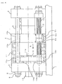
- Fig. 12 is a schematic view of the other conventional mold clamping mechanism described in the above Patent document.
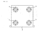
- Fig. 13 is a view taken in the direction of an arrow A in Fig. 12.
- the movable platen 4 is moved along the tie bars 5 with a ball spline mechanism composed of the ball spline nuts 6a, 6b provided in each tie bar insertion hole and a ball spline shaft 14 provided for each tie bar 5.
- the ball spline shaft of the above conventional mold clamping mechanism suffers a force inclusive of a mold clamping force, so that a diameter of the ball spline shaft needs to be sized equal to or larger than a diameter of each tie bar shaft.
- the above conventional mold clamping mechanism requires a ball spline shaft having a large diameter more than necessary, thereby providing disadvantages of causing an increase in cost, and besides, of being difficult to manufacture.
- each movable platen guide does not require such a large diameter as being enough to withstand the mold clamping force, in other words, may have a diameter adequate to effect guiding, so that a manufacture cost reduction is attainable, and besides, facilitation of manufacturing becomes also possible.
- the movable platen guides have an effect when application of the movable platen guides to a mold clamping mechanism of a large-sized molding machine is made.
- the mold clamping mechanism of a molding machine comprises a fixed platen mounted on a base frame of the molding machine, a rear platen; tie bars permitting the fixed platen to be connected to the rear platen, and a movable platen placed between the rear platen and the fixed platen, and is adapted to effect clamping of molds mounted to the movable platen and the fixed platen by moving the movable platen along the tie bars.
- the mold clamping mechanism has at least two pieces of movable platen guides, separate from the tie bars; the movable platen has movable platen guide insertion holes into which the movable platen guides are inserted; a sliding part of each of the movable platen guides on which at least the movable platen slides is given in the form of a ball spline shaft; and ball spline nuts are provided in the movable platen guide insertion holes of the movable platen.
- the mold clamping mechanism With the molds fixedly mounted to the movable platen and the fixed platen, the mold clamping mechanism according to the present invention effects closing, clamping and opening of the molds by moving the movable platen along the tie bars.
- each tie bar is fixed to the fixed platen and the rear platen.
- one end of each movable platen guide is fixed with the fixed platen, while the other end thereof is simply supported at the rear platen side.
- This arrangement is effective in causing the tie bars to bear the mold clamping force, while allowing the movable platen guides to effect only guiding of the movable platen without causing the movable platen guides to bear any mold clamping force.
- the ball spline nuts are provided in the movable platen guide insertion holes, and the sliding part of each movable platen guide on which at least the movable platen slides is given in the form of the ball spline shaft.
- the movable platen of the mold clamping mechanism according to the present invention is allowable to be composed of two members, specifically, a movable member and an auxiliary member fixed to a fixed platen-side surface of the movable member, and these two members are fixed with bolts or the like.
- the auxiliary member is effective in reducing an influence that movable platen strain caused by the mold clamping force has on the ball spline.
- the movable platen and the auxiliary member may be formed with different materials.
- the material having high rigidity used herein means a material that ensures high modulus of longitudinal elasticity.
- the movable platen formed with gray cast iron or spheroidal graphite cast iron is used, for instance, general structural rolled steel, general structural carbon steel or general structural alloyed steel having modulus of longitudinal elasticity about twice as high as that of the above movable platen material is used as a material of the auxiliary member.
- the movable platen requires a complicated structure, while the auxiliary member may have a simplified structure.
- the material having high modulus of longitudinal elasticity is hard to be machined, leading to an increase in cost.
- the present invention provides facilitation of machining to ensure that a cost reduction is attainable by using a material having a low modulus of longitudinal elasticity for a movable platen having the complicated structure, and by using a material having a high modulus of longitudinal elasticity for an auxiliary member having a simplified structure.
- the mold clamping mechanism of the molding machine according to the present invention may also have a guide support between the rear platen and the movable platen.
- the guide support is a member adapted to support the movable platen guides in an inserted condition, and is effective in supporting the movable platen guides, as a substitute of the rear platen.
- the guide support is connected to the rear platen through connection members.
- the present invention makes it possible to obtain the ball spline shaft whose diameter is small-sized, and to provide facilitation of manufacturing, with a cost reduction attained.
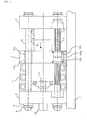
- a mold clamping mechanism according to a first embodiment of the present invention will now be described with reference to Fig. 1 to Fig. 4C.
- Fig. 1 is a schematic view showing the mold clamping mechanism according to the first embodiment of the present invention.
- the mold clamping mechanism shown in Fig. 1 has movable platen guides, and each movable platen guide has a ball spline shaft.
- a fixed platen 2 fixed in an upright position to a base frame 1 of a molding machine.
- One end of each of four pieces of tie bars 5 is fixed to the fixed platen 2, and a rear platen 3 is mounted to the other end of each of the tie bars 5.
- Oppositely facing surfaces of the fixed platen 2 and the rear platen 3 take a rectangular shape, and the tie bars 5 pass through the four corners of the above oppositely facing surfaces, respectively (one of the tie bars 5 is only shown in Fig. 1).
- the rear platen 3 is mounted to the tie bars 5 in a condition where movement of the rear platen is permitted along the tie bars 5 through mold thickness adjusting nuts 8.
- a pinion 9 is fitted to each nut 8.
- a chain (not shown) is mounted across a space between the pinions 9 of the respective tie bars 5.
- the nuts 8 of the respective tie bars 5 provide synchronous turning by driving the chain with a mold thickness adjusting motor (not shown), and as a result, the rear platen 3 moves nearer to or away from the fixed platen 2.
- the above rear platen motion is adapted to adjust a distance between the rear platen 3 and the fixed platen 2, thereby permitting adjustment on a thickness of a mold being in service and a mold clamping force.
- a movable platen 4 is placed between the fixed platen 2 and the rear platen 3 so as to be guided along the above four pieces of tie bars 5.
- a toggle mechanism 11 is placed between the rear platen 3 and the movable platen 4, and the rear platen 3 has a drive source 10 (specifically, a mold clamping servomotor) adapted to move a cross head 11a of the toggle mechanism 11.
- the movable platen 4 has tie bar insertion holes respectively having slide bearing bushes 15a, 15b.
- a slide bearing there may be provided a clearance between an inside surface of each tie bar insertion hole of the movable platen 4 and an outside surface of each tie bar 5 in such a manner that an inside diameter of each tie bar insertion hole of the movable platen 4 is sized larger than an outside diameter of each tie bar 5.
- one end of each of at least two pieces of movable platen guides 13 is also fixed to the fixed platen 2 with nuts or the like. Insertion of the other end of each of the movable platen guides 13 into a corresponding fit hole of the rear platen 3 allows an axial center of each movable platen guide 13 to be held in place in the range of prescribed accuracy.
- a guide support provided between the rear platen 3 and the movable platen 4 is also adaptable to support the other end of each movable platen guide, instead of supporting with the rear platen 3. A description of an arrangement of supporting with the guide support will be given later.
- Each movable platen guide 13 has a ball spline shaft 14 obtained by applying ball spline to a sliding range of each movable platen guide 13 on which at least the movable platen 4 slides.
- the movable platen 4 has ball spline nuts 6a, 6b at a portion permitting each movable platen guide 13 to pass through, and these ball spline nuts are adapted, together with the ball spline shaft 14 of each movable platen guide 13, to form a ball spline mechanism.
- the movable platen 4 having two pieces of ball spline nuts 6a, 6b.
- the number of ball spline nuts may be determined as desired.
- a length of a ball spline engagement part may increase with the increasing number of ball spline nuts, thereby providing an increased effect of preventing tilting variations of the movable platen 4.
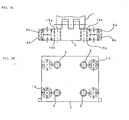
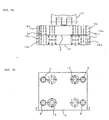
- FIG. 2A specified as a top view of the movable platen 4
- Fig. 2B specified as a view showing the movable platen 4 taken in the direction shown by an arrow A in Fig. 1.
- the movable platen 4 has two kinds of holes, specifically, holes permitting insertion of the tie bars 5 and another holes permitting insertion of the movable platen guides 13.
- Each of the holes permitting insertion of the tie bars 5 has the slide bearing bushes 15a, 15b.
- Each of the holes permitting insertion of the movable platen guides 13 has the ball spline nuts 6a, 6b, and these ball spline nuts 6a, 6b are engaged with the ball spline shaft 14 of each movable platen guide 13 into the ball spline mechanism.
- the above arrangement leads to insertion of the tie bars 5 into the movable platen 4 through the slide bearing bushes 15a, 15b and also insertion of the movable platen guides 13 into the movable platen 4 through the ball spline nuts 6a, 6b.
- a positional relationship between the movable platen guides 13 and the tie bars 5 is not limited to the above arrangement.
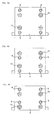
- the movable platen guides 13 may be also placed at the inside of the tie bars 5 (a second exemplified arrangement), as shown in Fig. 3A specified as a top view of the movable platen 4 and Fig. 3B specified as a view showing the movable platen 4 taken in the direction shown by the arrow A in Fig. 1.
- the movable platen guides 13 may be also placed above or below the tie bars 5 (a third exemplified arrangement), as shown in Fig. 4A.
- Fig. 4B shows a different arrangement (a fourth exemplified arrangement) in which the movable platen guides 13 are placed above the tie bars 5.
- Fig. 4C shows a further different arrangement (a fifth exemplified arrangement) in which the movable platen guides 13 are placed below the tie bars 5.
- Figs. 2B, 3B, 4A, 4B and 4C illustrate the arrangements of two pieces of movable platen guides 13 at positions shown by solid lines or chain lines, or those of four pieces of movable platen guides 13 at positions shown by solid lines and chain lines.
- reference numeral 16a in Fig. 1 denotes a platen support, which is operative between the movable platen 4 and the base frame 1 to adjust tilting of the platen.
- Molds are respectively mounted to the oppositely facing surfaces (not shown) of the fixed platen 2 and the movable platen 4. Specifically, a moving-side mold 17a is mounted to the movable platen 4, while a fixed-side mold 17b is mounted to the fixed platen 2. Then, the mold clamping mechanism drives the toggle mechanism 11 by driving the drive source 10 to effect closing, clamping and opening of the molds in such a manner as to move the movable platen 4 along the tie bars 5.
- the arrangement adopted in the conventional mold clamping mechanism is that the tie bars have the ball spline shafts.
- the mold clamping mechanism according to the first embodiment of the present invention is different from the above conventional mold clamping mechanism in that it has movable platen guides, separate from the tie bars, and a ball spline shaft is provided on each movable platen guide.
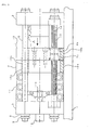
- Fig. 5 is a schematic view showing the mold clamping mechanism according to the second embodiment.
- the mold clamping mechanism shown in Fig. 5 has an auxiliary member joined with the movable platen, and the auxiliary member and the movable platen guides are adapted to form the ball spline mechanism.
- the mold clamping mechanism according to the second embodiment is different from the mold clamping mechanism according to the first embodiment in that it has an auxiliary member. It is noted that in the following description on the second embodiment, a description on an arrangement common to the first and second embodiments will be omitted.
- an auxiliary member 12 is placed between the fixed platen 2 and the rear platen 3, and four pieces of tie bars 5 and more than one movable platen guide 13 pass through the movable platen 4 and the auxiliary member 12, respectively.
- the auxiliary member 12 is in engagement with the movable platen 4 with fixing members such as bolts.
- each movable platen guide 13 has the ball spline shaft 14 formed by applying ball spline to a sliding range of each movable platen guide 13 on which at least the auxiliary member 12 slides.
- the auxiliary member 12 has movable platen guide insertion holes respectively having ball spline nuts 6a, 6b.
- the movable platen 4 has tie bar insertion holes respectively having slide bearing bushes 15a, 15b.
- the arrangement adopted in the conventional mold clamping mechanism is that insertion of the tie bars into the movable platen is performed in a condition where the holes of the movable platen have the ball spline nuts respectively.
- the mold clamping mechanism according to the second embodiment of the present invention is different from the above conventional mold clamping mechanism in that the movable platen is guided with the ball spline nuts provided in the holes of the auxiliary member fixed to one surface side of the movable platen.
- the movable platen and the auxiliary member engaged with each other may be formed with different materials.
- the material having high rigidity used herein means a material that ensures high modulus of longitudinal elasticity.
- general structural rolled steel, general structural carbon steel or general structural alloyed steel having modulus of longitudinal elasticity about twice as high as the above movable platen material is used as a material of the auxiliary member.
- the movable platen requires a complicated structure because a toggle mechanism is mounted on the movable platen, so that a low rigidity material that is easy to cast is generally used for the movable platen. Forming of the movable platen with the high rigidity material would lead to an increase in cost.
- the auxiliary member may have a simple structure, so that any complicated machining is not required.
- the mold clamping mechanism according to the second embodiment may provide facilitation of machining, and besides, may attain a cost reduction by forming the auxiliary member with the high rigidity material.
- the molds (specifically, the moving-side mold 17a and the fixed-side mold 17b) are mounted to the oppositely facing surfaces of the fixed platen 2 and the auxiliary member 12, respectively. Then, dividing the drive source 10, the mold clamping mechanism drives the toggle mechanism 11 to move the movable platen 4 and the auxiliary member 12 along the tie bars 5, thereby effecting mold closing, mold clamping and mold opening.
- the mold clamping force causes the movable platen 4, the auxiliary member 12 and the fixed platen 2 to be deformed, with the result that strain of the movable platen 4 is increased since the movable platen 4 is directly connected to the toggle mechanism 11.
- Fig. 6A specified as a top view of the movable platen 4
- Fig. 6B specified as a view showing the movable platen 4 taken in the direction shown by an arrow A in Fig. 5.
- the movable platen 4 has holes permitting insertion of the tie bars 5.
- the auxiliary member 12 has holes permitting insertion of the movable platen guides 13.
- the tie bar 5-insertion holes of the movable platen 4 have slide bearing bushes 15a, 15b.
- the movable platen guide insertion holes of the auxiliary member 12 have ball spline nuts 6a, 6b, and these ball spline nuts 6a, 6b are engaged with the ball spline shaft 14 of each movable platen guide 13. With these arrangement, a ball spline mechanism is consitituted.
- the above arrangement leads to insertion of the tie bars 5 into the movable platen 4 through the slide bearing bushes 15a, 15b and also insertion of the movable platen guides 13 into the auxiliary member 12 through the ball spline nuts 6a, 6b.
- a positional relationship between the movable platen guides 13 and the tie bars 5 is not limited to the above arrangement.
- the movable platen guides 13 may be also placed at the inside of the tie bars 5, for instance, as shown in Figs. 7A and 7B.
- FIGs. 6B and 7B illustrate the arrangements of two pieces of movable platen guides 13 at positions shown by solid lines or chain lines or those of four pieces of movable platen guides 13 at positions shown by solid lines and chain lines.
- Fig. 8 is a schematic view showing the mold clamping mechanism according to the third embodiment.
- the mold clamping mechanism shown in Fig. 8 has a guide support 18 between the movable platen 4 and the rear platen 3, and a mechanism adapted to support the movable platen guides 13 with the guide support 18 is involved in the above mold clamping mechanism.
- the mold clamping mechanism according to the third embodiment as shown in Fig. 8 is equivalent to a structure obtained by adding the guide support to the mold clamping mechanism (shown in Fig. 1) according to the first embodiment. It is thus noted that in the following description on the third embodiment, a different arrangement from the first embodiment will be only described without giving any description of the arrangement common to the first embodiment.
- the guide support 18 is placed between the movable platen 4 and the rear platen 3, and is supported in two locations with the tie bars 5 through a slide bearing bush 15c. Also, the guide support 18 is connected to the rear platen 3 through connection members 19a, 19b. Each of the connection members 19a, 19b may be an integral part of the rear platen 3. Alternatively, each of the connection members 19a, 19b and the rear platen 3 may be different parts. Further, the guide support 18 has a hole permitting insertion of one end of each movable platen guide 13 to ensure that insertion of each movable platen guide 13 into the hole of the guide support is adapted to support one end of each movable platen guide 13. The guide support 18 may also have a height adjusting support 16c.
- FIG. 9A An arrangement of the movable platen guides 13 and the tie bars 5 is shown in Fig. 9A specified as a top view of the guide support 18 and Fig. 9B specified as a view showing the guide support 18 taken in the direction shown by an arrow A in Fig. 8.
- Figs. 9A and 9B there are shown a pair of guide supports 18, specifically, left and right guide supports, and each of the guide supports has, in two locations, slide bearings 15c permitting insertion of the tie bars 5 and, in at least one location, a hole permitting insertion of the movable platen guide 13.
- the mold clamping mechanism having each guide support 18 for supporting one end of each movable platen guide 13, separate from the rear platen, enables vertical adjustment of one end of each movable platen guide 13 to be attained without causing the action of the support 16c on the rear platen.
- Fig. 10 is a schematic view showing the mold clamping mechanism according to the fourth embodiment.
- the mold clamping mechanism shown in Fig. 10 has the guide support 18 between the movable platen 4 and the rear platen 3, and the guide support 18 is adapted to support the movable platen guides 13.
- the mold clamping mechanism according to the fourth embodiment shown in Fig. 10 is equivalent to a structure obtained by adding the guide support to the mold clamping mechanism (See Fig. 5) according to the second embodiment. It is thus noted that in the following description on the fourth embodiment, a different arrangement from the second embodiment is only described without giving any description of the arrangement common to the first and second embodiments.
- the guide support 18 is placed between the movable platen 4 and the rear platen 3, and is supported in two locations with the tie bars 5 through the slide bearing bush 15c. Also, the guide support 18 is connected to the rear platen 3 through the connection members 19a, 19b. Each of the connection members 19a, 19b may be an integral part of the rear platen 3. Alternatively, each of the connection members 9a, 19b and the rear platen 3 may be different parts. Further, the guide support 18 has a hole permitting insertion of one end of each movable platen guide 13 to ensure that insertion of each movable platen guide 13 into the hole of the guide support is adapted to support one end of each movable platen guide 13. The guide support 18 may also have the height adjusting support 16c.
- the mold clamping mechanism (shown in Figs. 1, 5, 8 and 10) according to each of the first to fourth embodiments provides guiding of the movable platen guides 13 in such a manner as to allow one end of each movable platen guide 13 to be inserted into the hole of the rear platen 3 or the guide support 18, with the other end thereof fixed to the fixed platen 2.
- guiding of the movable platen guides 13 may be also provided in such a manner as to allow one end of each movable platen guide 13 to be inserted into the hole of the fixed platen 2, with the other end thereof fixed to the rear platen 3 or the guide support 18.
- the guide support 18 in the above third and fourth embodiments is supported in two locations with the tie bars 5 through the slide bearing bush 15c, and is also connected to the rear platen 3 through the connection members 19a, 19b.
- supporting and connection of the guide support 18 are not limited to the above method, and the guide support 18 may be also mounted in a vertical position on the base frame 1.
- the present invention makes it possible to obtain the ball spline shaft whose diameter is small-sized, and also to provide facilitation of manufacturing, with a cost reduction attained.
Landscapes
- Engineering & Computer Science (AREA)
- Manufacturing & Machinery (AREA)
- Mechanical Engineering (AREA)
- Moulds For Moulding Plastics Or The Like (AREA)
Abstract
Description
- This invention relates to a mold clamping mechanism in a molding machine such as an injection molding machine.
- Fig. 11 is a schematic view for use in an illustration of a conventional mold clamping mechanism of a molding machine such as an injection molding machine. In the conventional mold clamping mechanism of the molding machine such as the injection molding machine, a
fixed platen 2 is mounted in an upright position to abase frame 1 of the molding machine. Thefixed platen 2 is connected to arear platen 3 withtie bars 5, typically, four pieces of tie bars, and amovable platen 4 having through holes permitting thesetie bars 5 to pass through is placed between thefixed platen 2 and therear platen 3. With a moving-side mold 17a mounted to themovable platen 4, and with a fixed-side mold 17b mounted to thefixed platen 2, the conventional mold clamping mechanism drives themovable platen 4 with a drive source such as a motor and a hydraulic cylinder to effect clamping of themolds 17a and 17b in such a manner as to move themovable platen 4 with thetie bars 5 as guides. - The conventional mold clamping mechanism uses a slide bearing 15 for a sliding surface of the
movable platen 4 with eachtie bar 5. The through holes of the movable platen haveslide bearing bushes 15a, 15b to ensure that eachtie bar 5 passes through thebushes 15a, 15b. - The above conventional mold clamping mechanism requires the slide bearing at a sliding part of the movable platen with each tie bar, leading to an increase in clearance or play between an inside diameter of each slide bearing bush and an outside diameter of each tie bar. Thus, tilting of the movable platen is caused easily, resulting in degradation of the degree of parallelism between a surface of the moving-side mold mounted to the movable platen and a surface of the fixed-side mold mounted to the fixed platen.
- In Japanese Patent Application Laid-open No. 2001-260196, for instance, there is disclosed a mold clamping mechanism of a molding machine, in which a movable platen has tie bar insertion holes each having ball spline nuts, while a sliding part of each tie bar on which at least the movable platen slides is given in the form of a ball spline shaft to ensure that prevention of tilting of the movable platen is provided.
- Fig. 12 is a schematic view of the other conventional mold clamping mechanism described in the above Patent document. Fig. 13 is a view taken in the direction of an arrow A in Fig. 12. The
movable platen 4 is moved along thetie bars 5 with a ball spline mechanism composed of theball spline nuts 6a, 6b provided in each tie bar insertion hole and aball spline shaft 14 provided for eachtie bar 5. - The ball spline shaft of the above conventional mold clamping mechanism suffers a force inclusive of a mold clamping force, so that a diameter of the ball spline shaft needs to be sized equal to or larger than a diameter of each tie bar shaft. Thus, in application of the above arrangement to a large-sized molding machine, the above conventional mold clamping mechanism requires a ball spline shaft having a large diameter more than necessary, thereby providing disadvantages of causing an increase in cost, and besides, of being difficult to manufacture.
- In the mold clamping mechanism of a molding machine, according to the present invention, tilting of a movable platen is prevented by providing movable platen guides adapted to guide the movable platen, separate from tie bars, and by applying a ball spline to each of the movable platen guides. The movable platen guides of the mold clamping mechanism according to the present invention do not bear any mold clamping force, so that no additional large force is applied to the movable platen guides. Thus, each movable platen guide does not require such a large diameter as being enough to withstand the mold clamping force, in other words, may have a diameter adequate to effect guiding, so that a manufacture cost reduction is attainable, and besides, facilitation of manufacturing becomes also possible. In particular, the movable platen guides have an effect when application of the movable platen guides to a mold clamping mechanism of a large-sized molding machine is made.
- The mold clamping mechanism of a molding machine, according to the present invention comprises a fixed platen mounted on a base frame of the molding machine, a rear platen; tie bars permitting the fixed platen to be connected to the rear platen, and a movable platen placed between the rear platen and the fixed platen, and is adapted to effect clamping of molds mounted to the movable platen and the fixed platen by moving the movable platen along the tie bars. The mold clamping mechanism has at least two pieces of movable platen guides, separate from the tie bars; the movable platen has movable platen guide insertion holes into which the movable platen guides are inserted; a sliding part of each of the movable platen guides on which at least the movable platen slides is given in the form of a ball spline shaft; and ball spline nuts are provided in the movable platen guide insertion holes of the movable platen.
- With the molds fixedly mounted to the movable platen and the fixed platen, the mold clamping mechanism according to the present invention effects closing, clamping and opening of the molds by moving the movable platen along the tie bars.
- The opposite ends of each tie bar are fixed to the fixed platen and the rear platen. On the contrary, one end of each movable platen guide is fixed with the fixed platen, while the other end thereof is simply supported at the rear platen side. This arrangement is effective in causing the tie bars to bear the mold clamping force, while allowing the movable platen guides to effect only guiding of the movable platen without causing the movable platen guides to bear any mold clamping force. In the above arrangement, the ball spline nuts are provided in the movable platen guide insertion holes, and the sliding part of each movable platen guide on which at least the movable platen slides is given in the form of the ball spline shaft.
- No application of any mold clamping force to the movable platen guides is caused, so that the ball spline shaft does not need to have a large diameter, in other words, may have a diameter adequate to effect guiding. This arrangement enables the ball spline to be applied to an arrangement adaptable to provide prevention of tilting of the movable platen.
- The movable platen of the mold clamping mechanism according to the present invention is allowable to be composed of two members, specifically, a movable member and an auxiliary member fixed to a fixed platen-side surface of the movable member, and these two members are fixed with bolts or the like. The auxiliary member is effective in reducing an influence that movable platen strain caused by the mold clamping force has on the ball spline.
- In addition, the movable platen and the auxiliary member may be formed with different materials. A material having rigidity higher than that of a movable platen material, for instance, is used for the auxiliary member. The material having high rigidity used herein means a material that ensures high modulus of longitudinal elasticity. When the movable platen formed with gray cast iron or spheroidal graphite cast iron is used, for instance, general structural rolled steel, general structural carbon steel or general structural alloyed steel having modulus of longitudinal elasticity about twice as high as that of the above movable platen material is used as a material of the auxiliary member.
- In general, the movable platen requires a complicated structure, while the auxiliary member may have a simplified structure. The material having high modulus of longitudinal elasticity is hard to be machined, leading to an increase in cost. The present invention provides facilitation of machining to ensure that a cost reduction is attainable by using a material having a low modulus of longitudinal elasticity for a movable platen having the complicated structure, and by using a material having a high modulus of longitudinal elasticity for an auxiliary member having a simplified structure.
- Alternatively, the mold clamping mechanism of the molding machine according to the present invention may also have a guide support between the rear platen and the movable platen. The guide support is a member adapted to support the movable platen guides in an inserted condition, and is effective in supporting the movable platen guides, as a substitute of the rear platen. The guide support is connected to the rear platen through connection members.
- In the arrangement in which prevention of tilting of the movable platen is provided by using the ball spline shaft for the mold clamping mechanism, separate from the tie bars, the present invention makes it possible to obtain the ball spline shaft whose diameter is small-sized, and to provide facilitation of manufacturing, with a cost reduction attained.
- The foregoing and other objects and features of the invention will become more apparent in the following description of presently preferred embodiments of the invention taken in conjunction with the accompanying drawings, in which:
- Fig. 1 is a schematic view showing a mold clamping mechanism according to a first embodiment of the present invention;
- Figs. 2A and 2B illustrate a first exemplified arrangement of tie bars and movable platen guides in the mold clamping mechanism shown in Fig. 1;
- Figs. 3A and 3B illustrate a second exemplified arrangement of the tie bars and the movable platen guides in the mold clamping mechanism shown in Fig. 1;
- Figs. 4A to 4C illustrate third to fifth exemplified arrangements of the tie bars and the movable platen guides in the mold clamping mechanism shown in Fig. 1:
- Fig. 5 is a schematic view showing a mold clamping mechanism according to a second embodiment of the present invention;
- Figs. 6A and 6B illustrate a first exemplified arrangement of the tie bars and the movable platen guides in the mold clamping mechanism shown in Fig. 5;
- Figs. 7A and 7B illustrate a second exemplified arrangement of the tie bars and the movable platen guides in the mold clamping mechanism shown in Fig. 5;
- Fig. 8 is a schematic view showing a mold clamping mechanism according to a third embodiment of the present invention;
- Figs. 9A and 9B illustrate an exemplified arrangement of the tie bars and the movable platen guides in the mold clamping mechanism shown in Fig. 8;
- Fig. 10 is a schematic view showing a mold clamping mechanism according to a fourth embodiment of the present invention;
- Fig. 11 is a schematic view for use in an illustration of a conventional mold clamping mechanism of a molding machine such as an injection molding machine;
- Fig. 12 is a schematic view for use in an illustration of the other conventional mold clamping mechanism of the molding machine such as the injection molding machine; and
- Fig. 13 is a view taken along the direction shown by an arrow A in Fig. 12.
-
- A mold clamping mechanism according to a first embodiment of the present invention will now be described with reference to Fig. 1 to Fig. 4C.
- Fig. 1 is a schematic view showing the mold clamping mechanism according to the first embodiment of the present invention. The mold clamping mechanism shown in Fig. 1 has movable platen guides, and each movable platen guide has a ball spline shaft.
- In Fig. 1, there is shown a fixed
platen 2 fixed in an upright position to abase frame 1 of a molding machine. One end of each of four pieces of tie bars 5 is fixed to the fixedplaten 2, and arear platen 3 is mounted to the other end of each of the tie bars 5. Oppositely facing surfaces of the fixedplaten 2 and therear platen 3 take a rectangular shape, and the tie bars 5 pass through the four corners of the above oppositely facing surfaces, respectively (one of the tie bars 5 is only shown in Fig. 1). - While the fixed
platen 2 is fixed to the tie bars 5 with nuts, therear platen 3 is mounted to the tie bars 5 in a condition where movement of the rear platen is permitted along the tie bars 5 through mold thickness adjusting nuts 8. Apinion 9 is fitted to eachnut 8. A chain (not shown) is mounted across a space between thepinions 9 of the respective tie bars 5. Thenuts 8 of therespective tie bars 5 provide synchronous turning by driving the chain with a mold thickness adjusting motor (not shown), and as a result, therear platen 3 moves nearer to or away from the fixedplaten 2. The above rear platen motion is adapted to adjust a distance between therear platen 3 and the fixedplaten 2, thereby permitting adjustment on a thickness of a mold being in service and a mold clamping force. - Also, a
movable platen 4 is placed between the fixedplaten 2 and therear platen 3 so as to be guided along the above four pieces of tie bars 5. Atoggle mechanism 11 is placed between therear platen 3 and themovable platen 4, and therear platen 3 has a drive source 10 (specifically, a mold clamping servomotor) adapted to move a cross head 11a of thetoggle mechanism 11. - The
movable platen 4 has tie bar insertion holes respectively havingslide bearing bushes 15a, 15b.
Alternatively, in place of a slide bearing, there may be provided a clearance between an inside surface of each tie bar insertion hole of themovable platen 4 and an outside surface of eachtie bar 5 in such a manner that an inside diameter of each tie bar insertion hole of themovable platen 4 is sized larger than an outside diameter of eachtie bar 5. - In addition to the four pieces of tie bars 5, one end of each of at least two pieces of movable platen guides 13 is also fixed to the fixed
platen 2 with nuts or the like. Insertion of the other end of each of the movable platen guides 13 into a corresponding fit hole of therear platen 3 allows an axial center of eachmovable platen guide 13 to be held in place in the range of prescribed accuracy. Alternatively, a guide support provided between therear platen 3 and themovable platen 4 is also adaptable to support the other end of each movable platen guide, instead of supporting with therear platen 3. A description of an arrangement of supporting with the guide support will be given later. - Each
movable platen guide 13 has aball spline shaft 14 obtained by applying ball spline to a sliding range of eachmovable platen guide 13 on which at least themovable platen 4 slides. - The
movable platen 4 hasball spline nuts 6a, 6b at a portion permitting eachmovable platen guide 13 to pass through, and these ball spline nuts are adapted, together with theball spline shaft 14 of eachmovable platen guide 13, to form a ball spline mechanism. In the embodiment of Fig. 1, there is shown themovable platen 4 having two pieces ofball spline nuts 6a, 6b. Alternatively, the number of ball spline nuts may be determined as desired. A length of a ball spline engagement part may increase with the increasing number of ball spline nuts, thereby providing an increased effect of preventing tilting variations of themovable platen 4. - Arrangements of the tie bars 5 and the movable platen guides 13 in the mold clamping mechanism according to the first embodiment will be described in the following.
- A description of a first exemplified arrangement of the tie bars 5 and the movable platen guides 13 will be given with reference to Fig. 2A specified as a top view of the
movable platen 4 and Fig. 2B specified as a view showing themovable platen 4 taken in the direction shown by an arrow A in Fig. 1. - The
movable platen 4 has two kinds of holes, specifically, holes permitting insertion of the tie bars 5 and another holes permitting insertion of the movable platen guides 13. Each of the holes permitting insertion of the tie bars 5 has theslide bearing bushes 15a, 15b. Each of the holes permitting insertion of the movable platen guides 13 has theball spline nuts 6a, 6b, and theseball spline nuts 6a, 6b are engaged with theball spline shaft 14 of eachmovable platen guide 13 into the ball spline mechanism. - The above arrangement leads to insertion of the tie bars 5 into the
movable platen 4 through theslide bearing bushes 15a, 15b and also insertion of the movable platen guides 13 into themovable platen 4 through theball spline nuts 6a, 6b. - Although the arrangement in which the movable platen guides 13 are respectively placed at the outside of the tie bars 5 is shown in Figs. 2A and 2B, a positional relationship between the movable platen guides 13 and the tie bars 5 is not limited to the above arrangement.
- Alternatively, the movable platen guides 13 may be also placed at the inside of the tie bars 5 (a second exemplified arrangement), as shown in Fig. 3A specified as a top view of the
movable platen 4 and Fig. 3B specified as a view showing themovable platen 4 taken in the direction shown by the arrow A in Fig. 1. Alternatively, the movable platen guides 13 may be also placed above or below the tie bars 5 (a third exemplified arrangement), as shown in Fig. 4A. In addition, Fig. 4B shows a different arrangement (a fourth exemplified arrangement) in which the movable platen guides 13 are placed above the tie bars 5. Fig. 4C shows a further different arrangement (a fifth exemplified arrangement) in which the movable platen guides 13 are placed below the tie bars 5. - It is noted that Figs. 2B, 3B, 4A, 4B and 4C illustrate the arrangements of two pieces of movable platen guides 13 at positions shown by solid lines or chain lines, or those of four pieces of movable platen guides 13 at positions shown by solid lines and chain lines.
- It is also noted that reference numeral 16a in Fig. 1 denotes a platen support, which is operative between the
movable platen 4 and thebase frame 1 to adjust tilting of the platen. - Molds are respectively mounted to the oppositely facing surfaces (not shown) of the fixed
platen 2 and themovable platen 4. Specifically, a moving-side mold 17a is mounted to themovable platen 4, while a fixed-side mold 17b is mounted to the fixedplaten 2. Then, the mold clamping mechanism drives thetoggle mechanism 11 by driving thedrive source 10 to effect closing, clamping and opening of the molds in such a manner as to move themovable platen 4 along the tie bars 5. - Specifically, the arrangement adopted in the conventional mold clamping mechanism (See Japanese Patent Application Laid-open No. 2001-260196) is that the tie bars have the ball spline shafts. On the contrary, the mold clamping mechanism according to the first embodiment of the present invention is different from the above conventional mold clamping mechanism in that it has movable platen guides, separate from the tie bars, and a ball spline shaft is provided on each movable platen guide.
- The mold clamping mechanism according to a second embodiment of the present invention will be described in the following with reference to Fig. 5 to Fig. 7B.
- Fig. 5 is a schematic view showing the mold clamping mechanism according to the second embodiment. The mold clamping mechanism shown in Fig. 5 has an auxiliary member joined with the movable platen, and the auxiliary member and the movable platen guides are adapted to form the ball spline mechanism.
- The mold clamping mechanism according to the second embodiment is different from the mold clamping mechanism according to the first embodiment in that it has an auxiliary member. It is noted that in the following description on the second embodiment, a description on an arrangement common to the first and second embodiments will be omitted.
- In addition to the
movable platen 4, anauxiliary member 12 is placed between the fixedplaten 2 and therear platen 3, and four pieces oftie bars 5 and more than onemovable platen guide 13 pass through themovable platen 4 and theauxiliary member 12, respectively. Theauxiliary member 12 is in engagement with themovable platen 4 with fixing members such as bolts. - Further, each
movable platen guide 13 has theball spline shaft 14 formed by applying ball spline to a sliding range of eachmovable platen guide 13 on which at least theauxiliary member 12 slides. Theauxiliary member 12 has movable platen guide insertion holes respectively having ball spline nuts 6a, 6b. On the contrary, themovable platen 4 has tie bar insertion holes respectively havingslide bearing bushes 15a, 15b. Alternatively, in place of the slide bearing, there may be provided a clearance between an inside surface of each tie bar insertion hole of themovable platen 4 and an outside surface of eachtie bar 5 in such a manner that an inside diameter of each tie bar insertion hole of themovable platen 4 is sized larger than an outside diameter of eachtie bar 5. - Specifically, the arrangement adopted in the conventional mold clamping mechanism is that insertion of the tie bars into the movable platen is performed in a condition where the holes of the movable platen have the ball spline nuts respectively. On the contrary, the mold clamping mechanism according to the second embodiment of the present invention is different from the above conventional mold clamping mechanism in that the movable platen is guided with the ball spline nuts provided in the holes of the auxiliary member fixed to one surface side of the movable platen.
- The movable platen and the auxiliary member engaged with each other may be formed with different materials. A material having rigidity higher than that of a movable platen material, for instance, is used for the auxiliary member. The material having high rigidity used herein means a material that ensures high modulus of longitudinal elasticity. When the movable platen formed with gray cast iron or spheroidal graphite cast iron is used, general structural rolled steel, general structural carbon steel or general structural alloyed steel having modulus of longitudinal elasticity about twice as high as the above movable platen material is used as a material of the auxiliary member.
- The movable platen requires a complicated structure because a toggle mechanism is mounted on the movable platen, so that a low rigidity material that is easy to cast is generally used for the movable platen. Forming of the movable platen with the high rigidity material would lead to an increase in cost. On the contrary, the auxiliary member may have a simple structure, so that any complicated machining is not required. The mold clamping mechanism according to the second embodiment may provide facilitation of machining, and besides, may attain a cost reduction by forming the auxiliary member with the high rigidity material.
- Also, the molds (specifically, the moving-side mold 17a and the fixed-
side mold 17b) are mounted to the oppositely facing surfaces of the fixedplaten 2 and theauxiliary member 12, respectively. Then, dividing thedrive source 10, the mold clamping mechanism drives thetoggle mechanism 11 to move themovable platen 4 and theauxiliary member 12 along the tie bars 5, thereby effecting mold closing, mold clamping and mold opening. The mold clamping force causes themovable platen 4, theauxiliary member 12 and the fixedplaten 2 to be deformed, with the result that strain of themovable platen 4 is increased since themovable platen 4 is directly connected to thetoggle mechanism 11. On the contrary, strain of theauxiliary member 12 is reduced since theauxiliary member 12 is placed with themovable platen 4 put between theauxiliary member 12 and thetoggle mechanism 11. This arrangement is adaptable to decrease deformation applied to the ball spline nuts provided in theauxiliary member 12. - An exemplified arrangement of the tie bars 5 and the movable platen guides 13 in the second embodiment will be described in the following.
- A description of a first exemplified arrangement of the tie bars 5 and the movable platen guides 13 will be given with reference to Fig. 6A specified as a top view of the
movable platen 4 and Fig. 6B specified as a view showing themovable platen 4 taken in the direction shown by an arrow A in Fig. 5. - The
movable platen 4 has holes permitting insertion of the tie bars 5. Theauxiliary member 12 has holes permitting insertion of the movable platen guides 13. The tie bar 5-insertion holes of themovable platen 4 haveslide bearing bushes 15a, 15b. The movable platen guide insertion holes of theauxiliary member 12 haveball spline nuts 6a, 6b, and theseball spline nuts 6a, 6b are engaged with theball spline shaft 14 of eachmovable platen guide 13. With these arrangement, a ball spline mechanism is consitituted. - The above arrangement leads to insertion of the tie bars 5 into the
movable platen 4 through theslide bearing bushes 15a, 15b and also insertion of the movable platen guides 13 into theauxiliary member 12 through theball spline nuts 6a, 6b. - Although the arrangement in which the movable platen guides 13 are placed at the outside of the tie bars 5 is shown in Figs. 6A and 6B, a positional relationship between the movable platen guides 13 and the tie bars 5 is not limited to the above arrangement. Alternatively, the movable platen guides 13 may be also placed at the inside of the tie bars 5, for instance, as shown in Figs. 7A and 7B.
- It is noted that Figs. 6B and 7B illustrate the arrangements of two pieces of movable platen guides 13 at positions shown by solid lines or chain lines or those of four pieces of movable platen guides 13 at positions shown by solid lines and chain lines.
- The mold clamping mechanism according to a third embodiment of the present invention will be described in the following with reference to Figs. 8 and 9.
- Fig. 8 is a schematic view showing the mold clamping mechanism according to the third embodiment. The mold clamping mechanism shown in Fig. 8 has a
guide support 18 between themovable platen 4 and therear platen 3, and a mechanism adapted to support the movable platen guides 13 with theguide support 18 is involved in the above mold clamping mechanism. - The mold clamping mechanism according to the third embodiment as shown in Fig. 8 is equivalent to a structure obtained by adding the guide support to the mold clamping mechanism (shown in Fig. 1) according to the first embodiment. It is thus noted that in the following description on the third embodiment, a different arrangement from the first embodiment will be only described without giving any description of the arrangement common to the first embodiment.
- The
guide support 18 is placed between themovable platen 4 and therear platen 3, and is supported in two locations with the tie bars 5 through aslide bearing bush 15c. Also, theguide support 18 is connected to therear platen 3 throughconnection members 19a, 19b. Each of theconnection members 19a, 19b may be an integral part of therear platen 3. Alternatively, each of theconnection members 19a, 19b and therear platen 3 may be different parts. Further, theguide support 18 has a hole permitting insertion of one end of eachmovable platen guide 13 to ensure that insertion of eachmovable platen guide 13 into the hole of the guide support is adapted to support one end of eachmovable platen guide 13. Theguide support 18 may also have a height adjusting support 16c. - An arrangement of the movable platen guides 13 and the tie bars 5 is shown in Fig. 9A specified as a top view of the
guide support 18 and Fig. 9B specified as a view showing theguide support 18 taken in the direction shown by an arrow A in Fig. 8. In Figs. 9A and 9B, there are shown a pair of guide supports 18, specifically, left and right guide supports, and each of the guide supports has, in two locations,slide bearings 15c permitting insertion of the tie bars 5 and, in at least one location, a hole permitting insertion of themovable platen guide 13. - The mold clamping mechanism having each guide
support 18 for supporting one end of eachmovable platen guide 13, separate from the rear platen, enables vertical adjustment of one end of eachmovable platen guide 13 to be attained without causing the action of the support 16c on the rear platen. - The mold clamping mechanism according to a fourth embodiment of the present invention will be described with reference to Fig. 10. Fig. 10 is a schematic view showing the mold clamping mechanism according to the fourth embodiment. The mold clamping mechanism shown in Fig. 10 has the
guide support 18 between themovable platen 4 and therear platen 3, and theguide support 18 is adapted to support the movable platen guides 13. - The mold clamping mechanism according to the fourth embodiment shown in Fig. 10 is equivalent to a structure obtained by adding the guide support to the mold clamping mechanism (See Fig. 5) according to the second embodiment. It is thus noted that in the following description on the fourth embodiment, a different arrangement from the second embodiment is only described without giving any description of the arrangement common to the first and second embodiments.
- The
guide support 18 is placed between themovable platen 4 and therear platen 3, and is supported in two locations with the tie bars 5 through theslide bearing bush 15c. Also, theguide support 18 is connected to therear platen 3 through theconnection members 19a, 19b. Each of theconnection members 19a, 19b may be an integral part of therear platen 3. Alternatively, each of theconnection members 9a, 19b and therear platen 3 may be different parts. Further, theguide support 18 has a hole permitting insertion of one end of eachmovable platen guide 13 to ensure that insertion of eachmovable platen guide 13 into the hole of the guide support is adapted to support one end of eachmovable platen guide 13. Theguide support 18 may also have the height adjusting support 16c. - The mold clamping mechanism (shown in Figs. 1, 5, 8 and 10) according to each of the first to fourth embodiments provides guiding of the movable platen guides 13 in such a manner as to allow one end of each
movable platen guide 13 to be inserted into the hole of therear platen 3 or theguide support 18, with the other end thereof fixed to the fixedplaten 2. Alternatively, guiding of the movable platen guides 13 may be also provided in such a manner as to allow one end of eachmovable platen guide 13 to be inserted into the hole of the fixedplaten 2, with the other end thereof fixed to therear platen 3 or theguide support 18. - The
guide support 18 in the above third and fourth embodiments is supported in two locations with the tie bars 5 through theslide bearing bush 15c, and is also connected to therear platen 3 through theconnection members 19a, 19b. Alternatively, supporting and connection of theguide support 18 are not limited to the above method, and theguide support 18 may be also mounted in a vertical position on thebase frame 1. - As described the above, in the arrangement in which prevention of tilting of the movable platen is provided by using the ball spline shaft, the present invention makes it possible to obtain the ball spline shaft whose diameter is small-sized, and also to provide facilitation of manufacturing, with a cost reduction attained.
Claims (3)
- A mold clamping mechanism of a molding machine, which has a fixed platen mounted on a base frame of the molding machine, a rear platen, tie bars permitting said fixed platen to be connected to said rear platen, and a movable platen placed between said rear platen and said fixed platen, and is adapted to effect clamping of molds mounted to said movable platen and said fixed platen by moving the movable platen along said tie bars, wherein,
said mold clamping mechanism has at least two pieces of movable platen guides, separate from said tie bars;
said movable platen has movable platen guide insertion holes into which said movable platen guides are inserted;
a sliding part of each of said movable platen guides on which at least said movable platen slides is given in the form of a ball spline shaft; and
ball spline nuts are provided in said movable platen guide insertion holes of said movable platen. - The mold clamping mechanism of the molding machine according to claim 1, wherein said movable platen is composed of a movable member and an auxiliary member fixed to a fixed platen-side surface of the movable member.
- The mold clamping mechanism of the molding machine according to claim 1 or 2, wherein the mold clamping mechanism further has a guide support between said rear platen and said movable platen, said guide support being adapted to support said movable platen guides in an inserted condition.
Applications Claiming Priority (2)
| Application Number | Priority Date | Filing Date | Title |
|---|---|---|---|
| JP2003113344 | 2003-04-17 | ||
| JP2003113344 | 2003-04-17 |
Publications (2)
| Publication Number | Publication Date |
|---|---|
| EP1468807A1 true EP1468807A1 (en) | 2004-10-20 |
| EP1468807B1 EP1468807B1 (en) | 2006-11-02 |
Family
ID=32906068
Family Applications (1)
| Application Number | Title | Priority Date | Filing Date |
|---|---|---|---|
| EP04252107A Expired - Lifetime EP1468807B1 (en) | 2003-04-17 | 2004-04-08 | Mold clamping mechanism of injection molding machine |
Country Status (4)
| Country | Link |
|---|---|
| US (1) | US7134870B2 (en) |
| EP (1) | EP1468807B1 (en) |
| CN (1) | CN1285455C (en) |
| DE (1) | DE602004002976T2 (en) |
Cited By (2)
| Publication number | Priority date | Publication date | Assignee | Title |
|---|---|---|---|---|
| US12228173B2 (en) | 2020-02-06 | 2025-02-18 | Lego A/S | Bearing for linear guide rail |
| US12564990B2 (en) | 2020-02-06 | 2026-03-03 | Lego A/S | Main guide rail with internal track |
Families Citing this family (7)
| Publication number | Priority date | Publication date | Assignee | Title |
|---|---|---|---|---|
| CN101813107A (en) * | 2009-12-01 | 2010-08-25 | 东莞宏威数码机械有限公司 | Cylinder type lifting mechanism |
| CN102554678B (en) * | 2012-01-18 | 2015-07-08 | 太仓威格玛机械设备有限公司 | Movable double-table synchronous feeding mechanism |
| JP5670541B2 (en) * | 2013-03-26 | 2015-02-18 | ファナック株式会社 | Toggle type clamping mechanism of injection molding machine |
| JP6177217B2 (en) * | 2014-11-05 | 2017-08-09 | 日精樹脂工業株式会社 | Clamping device |
| DE102020117168A1 (en) * | 2020-06-30 | 2021-12-30 | Arburg Gmbh + Co Kg | Mold clamping unit for an injection molding machine for processing plastics |
| CN112743761A (en) * | 2020-11-27 | 2021-05-04 | 马鞍山恒粤塑胶有限公司 | Quick injection mold of laundry detergent packaging bottle |
| JP7535462B2 (en) | 2021-02-05 | 2024-08-16 | 株式会社日本製鋼所 | Mold clamping device and injection molding machine |
Citations (6)
| Publication number | Priority date | Publication date | Assignee | Title |
|---|---|---|---|---|
| JPS61188121A (en) * | 1985-02-18 | 1986-08-21 | Meiki Co Ltd | Mold clamping device of injection molder |
| JPS63242512A (en) * | 1987-03-30 | 1988-10-07 | Nissei Plastics Ind Co | Mold clamping apparatus |
| US4781568A (en) * | 1985-02-22 | 1988-11-01 | Fanuc Ltd. | Mold clamping unit of injection molding machine |
| US5378141A (en) * | 1992-08-31 | 1995-01-03 | Nissei Plastic Industrial Co., Ltd. | Motor driven type die tightening apparatus for an injection molding machine |
| JPH1128747A (en) * | 1997-07-10 | 1999-02-02 | Toyo Mach & Metal Co Ltd | Mold clamping device of molding machine |
| CA2235262A1 (en) * | 1998-04-21 | 1999-10-21 | Tradesco Mold Limited | Mold centering arrangement for injection molding apparatus |
Family Cites Families (3)
| Publication number | Priority date | Publication date | Assignee | Title |
|---|---|---|---|---|
| US3642403A (en) * | 1969-06-02 | 1972-02-15 | Jaroslav J Havlik | Injection molding machine |
| JPH07156232A (en) * | 1993-12-04 | 1995-06-20 | Enomoto:Kk | Molding machine |
| JP3330578B2 (en) | 2000-03-16 | 2002-09-30 | ファナック株式会社 | Mold clamping mechanism of molding machine |
-
2004
- 2004-04-06 US US10/817,916 patent/US7134870B2/en not_active Expired - Fee Related
- 2004-04-08 DE DE602004002976T patent/DE602004002976T2/en not_active Expired - Lifetime
- 2004-04-08 CN CN200410030774.5A patent/CN1285455C/en not_active Expired - Fee Related
- 2004-04-08 EP EP04252107A patent/EP1468807B1/en not_active Expired - Lifetime
Patent Citations (6)
| Publication number | Priority date | Publication date | Assignee | Title |
|---|---|---|---|---|
| JPS61188121A (en) * | 1985-02-18 | 1986-08-21 | Meiki Co Ltd | Mold clamping device of injection molder |
| US4781568A (en) * | 1985-02-22 | 1988-11-01 | Fanuc Ltd. | Mold clamping unit of injection molding machine |
| JPS63242512A (en) * | 1987-03-30 | 1988-10-07 | Nissei Plastics Ind Co | Mold clamping apparatus |
| US5378141A (en) * | 1992-08-31 | 1995-01-03 | Nissei Plastic Industrial Co., Ltd. | Motor driven type die tightening apparatus for an injection molding machine |
| JPH1128747A (en) * | 1997-07-10 | 1999-02-02 | Toyo Mach & Metal Co Ltd | Mold clamping device of molding machine |
| CA2235262A1 (en) * | 1998-04-21 | 1999-10-21 | Tradesco Mold Limited | Mold centering arrangement for injection molding apparatus |
Non-Patent Citations (3)
| Title |
|---|
| PATENT ABSTRACTS OF JAPAN vol. 0110, no. 10 (M - 552) 10 January 1987 (1987-01-10) * |
| PATENT ABSTRACTS OF JAPAN vol. 0130, no. 28 (M - 788) 23 January 1989 (1989-01-23) * |
| PATENT ABSTRACTS OF JAPAN vol. 1999, no. 05 31 May 1999 (1999-05-31) * |
Cited By (2)
| Publication number | Priority date | Publication date | Assignee | Title |
|---|---|---|---|---|
| US12228173B2 (en) | 2020-02-06 | 2025-02-18 | Lego A/S | Bearing for linear guide rail |
| US12564990B2 (en) | 2020-02-06 | 2026-03-03 | Lego A/S | Main guide rail with internal track |
Also Published As
| Publication number | Publication date |
|---|---|
| CN1537712A (en) | 2004-10-20 |
| US20040208952A1 (en) | 2004-10-21 |
| EP1468807B1 (en) | 2006-11-02 |
| US7134870B2 (en) | 2006-11-14 |
| DE602004002976D1 (en) | 2006-12-14 |
| DE602004002976T2 (en) | 2007-02-08 |
| CN1285455C (en) | 2006-11-22 |
Similar Documents
| Publication | Publication Date | Title |
|---|---|---|
| JP3792663B2 (en) | Molding mechanism of molding machine | |
| JP5670541B2 (en) | Toggle type clamping mechanism of injection molding machine | |
| JP3938281B2 (en) | Electric switchgear | |
| JP3655616B2 (en) | Injection molding machine | |
| EP1468807B1 (en) | Mold clamping mechanism of injection molding machine | |
| JP4249637B2 (en) | Molding mechanism of injection molding machine | |
| JP3914937B2 (en) | Molding mechanism of injection molding machine | |
| JP2002154146A (en) | Motor driven type opening/closing device | |
| CN107249839A (en) | Movable plate, opening and closing device and building mortion | |
| JP3764464B2 (en) | Molding mechanism of molding machine | |
| JP2002327826A (en) | Ball screw device and motor driven closing gear for injection molding machine | |
| JP5372331B2 (en) | Clamping device | |
| US20030147989A1 (en) | Die clamping unit of an injection molding machine | |
| US20040052893A1 (en) | Closing device in an injection moulding machine for synthetic materials | |
| JP4287841B2 (en) | Horizontal mold clamping device for injection molding machine | |
| JP4594717B2 (en) | Molding machine | |
| JP2009214124A (en) | Slide inclination reduction method, and slide inclination reduction device | |
| JP4963057B2 (en) | Injection molding machine | |
| JP2584325B2 (en) | Mold clamping device of injection molding machine | |
| JP5409533B2 (en) | Molding equipment | |
| JP4513594B2 (en) | Injection molding machine | |
| JP2005144762A (en) | Injection molding machine | |
| CN110198831A (en) | Frame construction, processing unit (plant), the manufacturing method of component, the manufacturing method of rolling bearing, the manufacturing method of vehicle, mechanical manufacturing method and stamping device | |
| JPH072186Y2 (en) | Ejector device of injection molding machine | |
| JPH0825099A (en) | Press machine |
Legal Events
| Date | Code | Title | Description |
|---|---|---|---|
| PUAI | Public reference made under article 153(3) epc to a published international application that has entered the european phase |
Free format text: ORIGINAL CODE: 0009012 |
|
| AK | Designated contracting states |
Kind code of ref document: A1 Designated state(s): AT BE BG CH CY CZ DE DK EE ES FI FR GB GR HU IE IT LI LU MC NL PL PT RO SE SI SK TR |
|
| AX | Request for extension of the european patent |
Extension state: AL HR LT LV MK |
|
| 17P | Request for examination filed |
Effective date: 20041229 |
|
| 17Q | First examination report despatched |
Effective date: 20050202 |
|
| AKX | Designation fees paid |
Designated state(s): DE |
|
| GRAP | Despatch of communication of intention to grant a patent |
Free format text: ORIGINAL CODE: EPIDOSNIGR1 |
|
| GRAS | Grant fee paid |
Free format text: ORIGINAL CODE: EPIDOSNIGR3 |
|
| GRAA | (expected) grant |
Free format text: ORIGINAL CODE: 0009210 |
|
| AK | Designated contracting states |
Kind code of ref document: B1 Designated state(s): DE |
|
| REF | Corresponds to: |
Ref document number: 602004002976 Country of ref document: DE Date of ref document: 20061214 Kind code of ref document: P |
|
| PLBE | No opposition filed within time limit |
Free format text: ORIGINAL CODE: 0009261 |
|
| STAA | Information on the status of an ep patent application or granted ep patent |
Free format text: STATUS: NO OPPOSITION FILED WITHIN TIME LIMIT |
|
| 26N | No opposition filed |
Effective date: 20070803 |
|
| PGFP | Annual fee paid to national office [announced via postgrant information from national office to epo] |
Ref country code: DE Payment date: 20100430 Year of fee payment: 7 |
|
| PG25 | Lapsed in a contracting state [announced via postgrant information from national office to epo] |
Ref country code: DE Free format text: LAPSE BECAUSE OF NON-PAYMENT OF DUE FEES Effective date: 20111101 |
|
| REG | Reference to a national code |
Ref country code: DE Ref legal event code: R119 Ref document number: 602004002976 Country of ref document: DE Effective date: 20111101 |