EP1468788B1 - Fuel cell adapter system for combustion tools - Google Patents
Fuel cell adapter system for combustion tools Download PDFInfo
- Publication number
- EP1468788B1 EP1468788B1 EP04291000A EP04291000A EP1468788B1 EP 1468788 B1 EP1468788 B1 EP 1468788B1 EP 04291000 A EP04291000 A EP 04291000A EP 04291000 A EP04291000 A EP 04291000A EP 1468788 B1 EP1468788 B1 EP 1468788B1
- Authority
- EP
- European Patent Office
- Prior art keywords
- fuel cell
- adapter
- nipple
- stem
- fuel
- Prior art date
- Legal status (The legal status is an assumption and is not a legal conclusion. Google has not performed a legal analysis and makes no representation as to the accuracy of the status listed.)
- Expired - Lifetime
Links
- 239000000446 fuel Substances 0.000 title claims abstract description 154
- 238000002485 combustion reaction Methods 0.000 title claims abstract description 20
- 210000002445 nipple Anatomy 0.000 claims abstract description 42
- 238000004891 communication Methods 0.000 claims abstract description 9
- 239000012530 fluid Substances 0.000 claims abstract description 9
- 239000012528 membrane Substances 0.000 description 10
- 239000000463 material Substances 0.000 description 8
- 238000007789 sealing Methods 0.000 description 7
- 230000002093 peripheral effect Effects 0.000 description 6
- 230000015572 biosynthetic process Effects 0.000 description 4
- 238000010276 construction Methods 0.000 description 3
- 230000000295 complement effect Effects 0.000 description 2
- 230000000994 depressogenic effect Effects 0.000 description 2
- 238000003780 insertion Methods 0.000 description 2
- 230000037431 insertion Effects 0.000 description 2
- 238000009434 installation Methods 0.000 description 2
- 230000001681 protective effect Effects 0.000 description 2
- 239000004215 Carbon black (E152) Substances 0.000 description 1
- 230000000903 blocking effect Effects 0.000 description 1
- 238000007664 blowing Methods 0.000 description 1
- 239000002131 composite material Substances 0.000 description 1
- 230000006835 compression Effects 0.000 description 1
- 238000007906 compression Methods 0.000 description 1
- 238000005516 engineering process Methods 0.000 description 1
- 229920005558 epichlorohydrin rubber Polymers 0.000 description 1
- 229930195733 hydrocarbon Natural products 0.000 description 1
- 150000002430 hydrocarbons Chemical class 0.000 description 1
- 239000012535 impurity Substances 0.000 description 1
- 230000013011 mating Effects 0.000 description 1
- 239000000203 mixture Substances 0.000 description 1
- 238000000465 moulding Methods 0.000 description 1
- 239000003380 propellant Substances 0.000 description 1
- 239000012858 resilient material Substances 0.000 description 1
- 230000035939 shock Effects 0.000 description 1
- 230000003319 supportive effect Effects 0.000 description 1
- 230000008961 swelling Effects 0.000 description 1
- 230000000007 visual effect Effects 0.000 description 1
Images


Classifications
-
- B—PERFORMING OPERATIONS; TRANSPORTING
- B25—HAND TOOLS; PORTABLE POWER-DRIVEN TOOLS; MANIPULATORS
- B25C—HAND-HELD NAILING OR STAPLING TOOLS; MANUALLY OPERATED PORTABLE STAPLING TOOLS
- B25C1/00—Hand-held nailing tools; Nail feeding devices
- B25C1/08—Hand-held nailing tools; Nail feeding devices operated by combustion pressure
-
- B—PERFORMING OPERATIONS; TRANSPORTING
- B66—HOISTING; LIFTING; HAULING
- B66C—CRANES; LOAD-ENGAGING ELEMENTS OR DEVICES FOR CRANES, CAPSTANS, WINCHES, OR TACKLES
- B66C7/00—Runways, tracks or trackways for trolleys or cranes
- B66C7/12—Devices for changing direction of travel or for transferring from one runway to another; Crossings; Combinations of tracks of different gauges
- B66C7/14—Runway interlocking devices
-
- B—PERFORMING OPERATIONS; TRANSPORTING
- B66—HOISTING; LIFTING; HAULING
- B66C—CRANES; LOAD-ENGAGING ELEMENTS OR DEVICES FOR CRANES, CAPSTANS, WINCHES, OR TACKLES
- B66C11/00—Trolleys or crabs, e.g. operating above runways
- B66C11/16—Rope, cable, or chain drives for trolleys; Combinations of such drives with hoisting gear
-
- B—PERFORMING OPERATIONS; TRANSPORTING
- B66—HOISTING; LIFTING; HAULING
- B66C—CRANES; LOAD-ENGAGING ELEMENTS OR DEVICES FOR CRANES, CAPSTANS, WINCHES, OR TACKLES
- B66C2700/00—Cranes
- B66C2700/01—General aspects of mobile cranes, overhead travelling cranes, gantry cranes, loading bridges, cranes for building ships on slipways, cranes for foundries or cranes for public works
- B66C2700/012—Trolleys or runways
Landscapes
- Engineering & Computer Science (AREA)
- Mechanical Engineering (AREA)
- Chemical & Material Sciences (AREA)
- Combustion & Propulsion (AREA)
- Portable Nailing Machines And Staplers (AREA)
- Feeding And Controlling Fuel (AREA)
- Fuel Cell (AREA)
Abstract
Description
- This invention relates to improvements in fuel cell adapter systems for use in combustion tools. As exemplified in U.S. Patent Nos. 4,403,722, 4,483,474, 4,522,162, and 5,115,944, it is known to use a dispenser to dispense a hydrocarbon fuel to a combustion gas-powered tool, such as, for example, a combustion gas-powered fastener-driving tool. Such fastener-driving tools and such fuel cells are available commercially from ITW-Paslode (a division of Illinois Tool Works, Inc.) of Vernon Hills, Illinois, under its IMPULSE trademark. In particular, a suitable fuel cell is described in U.S. Patent No. 5,115,944, listed above.
- A standard system for attaching a fuel cell to a combustion tool is known, i.e. placing the fuel cell into the combustion tool with a metering unit such as a valve, and having no adapter. This system has the advantage of being compact, however it does not protect the female metering unit inlet from dirt and other debris. Also, when not using an adapter, a protective cap or blister pack is needed for transporting the fuel cell.
- There is another known fuel cell attachment system for combustion tools, where a sleeve-like seal support adapter attaches to a fuel cell and creates a seal for joining the fuel cell stem and a male joiner from the combustion tool. However, this adapter system does not protect the fuel cell from dirt and other debris. Another disadvantage is that the presence of this adapter alone is believed to diminish the life and capacity of the fuel cell.
- One disadvantage of conventional combustion tool fuel cells as described above is that the conventional alignment structures employed for aligning the corresponding stems or passageways of the fuel cell and the tool fuel metering unit or valve do not provide consistent coaxial alignment of these passageways, which may lead to wasted fuel, shortened fuel cell life and less than optimal performance.
- A related design problem of conventional combustion tool fuel cells is that proper alignment needs to be maintained between the fuel cell stem and the tool metering valve nipple, both during installation of the fuel cell into the tool and when exposed to the relatively rough, construction site or workshop working environment of such tools.
- Maintaining a proper seal between the fuel cell stem and the tool metering valve nipple is also a problem, in that the seal needs to prevent the escape of fuel, while accommodating the sliding action of the fuel cell stem relative to the seal and the nipple as the fuel cell is inserted into, or withdrawn from the tool. Upon insertion into the tool, the fuel cell stem must be depressed into the fuel cell to permit the release of fuel. Further, if the fuel cell is removed from the tool before it is empty, the stem must be allowed to return to its closed or extended position to prevent fuel leakage.
- Accordingly, there is a need for an improved fuel cell attachment system that protects the fuel cell from dirt and other debris while in use. In addition, there is a need for a fuel cell adapter system which maintains a positive, aligned engagement between the fuel cell stem and the tool fuel metering valve nipple, both during operation and insertion or removal of the fuel cell from the tool.
- US-B1-6 217 085 discloses the preamble of
claim 1. EP-A-1 197 299 teaches a fuel cell adapter configured for connection to a fuel cell which is engageable upon a fuel metering valve of a combustion tool, the fuel cell having a stem and the metering valve having a nipple, said adapter comprising : - an adapter body having a base configured for engagement upon the fuel cell and a nozzle connected to said base ;
- said adapter body defining a chamber configured for accommodating the stem and the nipple; and
- an insert seal comprising a body defining a central passageway and having a fuel cell end and a valve nipple end, said passageway being provided for fluid communication between said fuel cell end and valve nipple end.
- The object of the invention of the instant case is to improve the way the adapter is secured to the fuel cell.
- The above-listed needs are met or exceeded by the fuel cell adapter according to
claim 1 and a combustion tool according toclaim 11. In the preferred embodiment, the fuel cell end of said body of said insert seal is configured for matingly receiving a free end of the stem. - More advantageously, the boss of said flange portion is configured for sealingly engaging an end of the nipple.
- The invention shall be better understood upon reading the following description, with reference to the attached drawings.
-
- Fig. 1 is a perspective view of a combustion tool incorporating the present invention;
- Fig.2 is a fragmentary exploded perspective view of the present adapter and the fuel cell ;
- Fig.3 is a fragmentary exploded perspective view of the present adapter, the insert seal and the fuel cell;
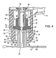
- Fig.4 is a fragmentary vertical section of the present fuel cell adapter system depicting the adapter and molded insert seal engaged with the fuel cell, prior to depression of the fuel cell stem;
- Fig.5 is a fragmentary vertical section of the assembly of Fig.4 showing full engagement of the fuel cell and adapter with the tool fuel metering valve;
- Fig.6 is a perspective view of an insert seal for use with the present adapter;
- Fig.7 is a reverse perspective view of the seal of Fig. 6;
- Fig. 8 is a section taken along the line 8-8 of Fig.7 and in the direction generally indicated;
- Fig. 9 is a perspective view of an alternate embodiment of the insert seal of Fig.7.
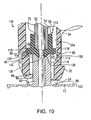
- FIG. 10 is a composite section similar to FIGs. 4 and 5 of an alternate embodiment of the present insert seal and fuel cell adapter; and
- FIG. 11 is a perspective view of another alternate embodiment of the present fuel cell adapter.
- Referring now to FIG. 1, a combustion-powered tool of the type suitable for use with the present invention is generally designated 10. The
tool 10 includes ahousing 11 enclosing afuel metering valve 12, and afuel cell chamber 13 which releasably houses afuel cell 14. The construction and operation of thetool 10 is described in detail in the documents and referred to above. While a trim-type tool is depicted, it is contemplated that the present invention may be used with any type of combustion tool employing a fuel cell. - In FIGS. 2 and 3, a fuel cell adapter, generally designated 16, is configured for connection to the
fuel cell 14, and facilitates engagement of the fuel cell in thefuel cell chamber 13. Anadapter body 18 has a generallycylindrical nozzle 20 and abase 22 configured for engagement upon thefuel cell 14, and the nozzle is connected to the base. Thenozzle 20 of thebody 18 has afree end 24 and defines achamber 26 which is preferably generally axial, with afrangible membrane 28 blocking thechamber 26. Thisfrangible membrane 28 has ahole 30 that allows for air escape, and it is preferably disposed at or adjacent thefree end 24 of thenozzle 20 for visually indicating tampering when ruptured. However, other locations along thechamber 26 are contemplated for themembrane 28. In a preferred embodiment, the diameter of thehole 30 measures about 0,25 mm, however the diameter may vary depending on the application. - On the
adapter body 18, thenozzle 20 has a plurality oflugs 32, and a plurality ofsupport ribs 34. Thelugs 32 each preferably have a ramped configuration, extending in an inclined configuration from thefree end 24 toward thebase 22, and each preferably has atruncated lug end 36. The generally L-shaped support ribs 34 each preferably have a truncatedrib end 38, and are configured for connecting thenozzle 20 to thebase 22. In the preferred embodiment,individual lugs 32 andsupport ribs 34 are circumferentially spaced from each other, and the spacing of the lugs relative to thesupport ribs 34 is staggered, so that the lugs and support ribs are not in axial alignment with each other. Also, theribs 34 hold thebase 22 in a radially
spaced relationship to thenozzle 20. It is contemplated that this configuration may change in view of tool, fuel cell and/or material performance requirements associated with particular applications. - In the preferred embodiment, the
adapter 16 is provided with agripping formation 40 which is configured for being engaged by a latch (not shown) disposed in thefuel cell chamber 13 of thehousing 11. Thisgripping formation 40 may have a variety of shapes. In the embodiment depicted in FIGs. 2-5, correspondingtruncated lug ends 36 and therib ends 38 of thelugs 32 and thesupport ribs 34 define agroove 40 that is disposed on thenozzle 20. Although it is preferred that theadapter body 18 have agripping formation 40 in the form of a groove as just described, it is also contemplated that the gripping formation is alternatively a rib or protrusion, generally radially extending from theadapter body 18. Such protrusions may form an annular rib or may also be individual, spaced, lugs or rib segments. - Also in a preferred embodiment, the
lugs 32 are radially spaced relative to each other, and the support ribs are radially spaced relative to each other. Thelugs 32 are also axially skewed, in other words, are not axially aligned relative to the opposing correspondingsupport ribs 34. Thus, as depicted in FIGs. 2 and 3, a staggered relationship is defined between thelugs 32 and thesupport ribs 34. - There is at least one
barb 42 formed on the base 22 configured for frictionally engaging thefuel cell 14. In a preferred embodiment, there is a plurality ofbarbs 42 disposed in a radially extending fashion around the exterior of thebase 22. - Referring now to FIGs. 3-8, the
adapter body 18 houses aninsert seal 44 which fits in thechamber 26. Theinsert seal 44 includes abody 46 defining an axial passageway 48 (best seen in FIGs. 4 and 5). In addition, theinsert seal 44 has a first orfuel cell end 50 configured for receiving afuel cell stem 52, and a second or valve nipple end 54 configured for sealingly engaging a fuelmetering valve nipple 56 which projects from thevalve 12. Aflange portion 58 is affixed, preferably by integrally forming or molding, or attaching by known technologies the flange portion to thebody 46 at thevalve nipple end 54. Theflange portion 58 thus defines the sealing location for thevalve nipple 56 once thefuel cell 14 is operationally engaged on thetool 10. - It will be seen that, in the preferred embodiment, the
insert seal body 46 is preferably cylindrical (however other shapes are contemplated, such as polygonal), and has a diameter or height "D" (FIG. 8). It will be further seen that theflange portion 58 has a larger diameter "Da" (FIG. 8) than the diameter D of thebody 46. To maintain fluid communication between thevalve nipple 56 and thefuel cell stem 52, theflange portion 58 has anopening 60 in fluid communication with thepassageway 48. - To obtain a positive sealing relationship with the
valve nipple 56, theflange portion 58 has aboss 62 on anouter surface 64 of the flange portion. In the preferred embodiment, the boss is centrally located on theouter surface 64 and has a diameter "d" (FIG. 8) which is smaller than the diameter "D" of theseal body 46. - Referring now to FIG. 6, it will be seen that the
flange portion 58 has a periphery defining asurface 66 which is generally parallel to a longitudinal axis of theseal body 46. In the preferred embodiment, theperipheral surface 66 is faceted, being made ofseveral facets 68 joined by radiused or roundedcorners 70. However, sharp or non-radiused corners are also contemplated. Theseal 44 is configured so that thecorners 70 are the points of sliding contact with thechamber 26. It is preferred that the diameter "Da" of theflange portion 58 is dimensioned to maintain the relatively low resistance sliding relationship in thechamber 26, while still providing a centering function for preserving the alignment of the fuel cell stem 52 with thefuel valve nipple 56. Improper alignment of these two tool components has been known to reduce fuel cell life and/or impair performance. While in the preferred embodiment, thesurface 66 is hexagonal, it will be understood that a number of polygonal shapes are contemplated as being suitable, depending on the application. - At the opposite end from the
flange portion 58, theinsert seal body 46 defines arecess 72 configured for matingly accommodating thefuel cell stem 52. To provide for fluid communication between thefuel cell 14 and themetering valve 12, therecess 72 has an opening 74 (FIG. 8) which is in fluid communication with, and preferably coextensive with, theopening 60 in theflange portion 58, and being part of thepassageway 48. - Referring now to FIG. 9, while it is preferred that the
peripheral surface 66 of theflange portion 58 is polygonaly faceted, it is also contemplated that the surface can be generally circular. In FIG. 9, an alternate insert seal is generally designated 76, and features which are shared with theseal 44 are designated with identical reference numbers. The main distinction between theseal 44 and theseal 76 is that theseal 76 is provided with aflange portion 78 having aperipheral edge surface 80 which is generally circular. It will be understood that the diameter "Da" of theflange portion 78 is dimensioned to promote the sliding/centering relationship discussed above in relation to theflange portion 58. Thus, among other things, the diameter "Da" may vary depending on the relative coefficient of friction between theflange portion 78 and the chamber, and the type of fuel cell valve and valve stem employed. - Regardless of the shape of the
peripheral surface chamber 26, theflange portions stem 52 in theadapter 16 and maintain proper alignment between the stem and thevalve nipple 56. The insert seals 44 and 76 also support the engagement between thestem 52 and thenipple 56 during operation of thetool 10 to the extent that no other support is needed for the stem-nipple connection. - While both the
seals chamber 26, depending on the application, the materials used for theadapter 16 in general and thebody 18 in particular, as well as materials used for theinsert seal adapter 16. Specifically, theseals insert seal - Another feature of the insert seals 44 and 76 is that a sealing relationship between the
valve nipple 56 and the insert seals 44 and 76 is created by the mating engagement between theboss 62 and a counterbore 82 (FIGS. 4 and 5) formed at the end of the fuelmetering valve nipple 56. Thecounterbore 82 defines a space configured for providing a relatively large surface area for contacting theboss 62. Theboss 62 is configured to interlock with thecounterbore 82. More specifically, theboss 62 is generally tapered or inclined from its base towards its outermost end (best seen in FIGs. 7 and 8). This shape, in conjunction with the resilient material used to form theinsert seal valve nipple 56. The counterbore portion of the preferablymetallic valve nipple 56 forms a sharp edge which "bites" into theboss 62 upon operational engagement of theadapter 16 and its associatedfuel cell 14 upon thetool 10. - To minimize fuel leakage, when the
fuel cell 14 is withdrawn from thefuel cell chamber 13, as is well known in the art, thestem 52 is designed to snap to a fully extended position which closes an internal fuel cell valve (not shown) and prevents the escape of fuel. As such, theinsert seal recess 72, is configured to permit thestem 26 to slide to its original sealed position as soon as thefuel cell 14, with its attachedadapter 16, is disengaged from themetering valve 12. - In the preferred embodiment, the
adapter 16 is provided with other optional features which improve performance. While in use, thefrangible membrane 28 has the advantage of protecting thefuel cell 14 from dirt and other debris. Adjacent themembrane 28, theadapter 16 is preferably provided with a plurality of optional lobes 90 (best seen in FIGs. 4 and 5) that facilitate operational engagement upon thevalve nipple 56. In the preferred embodiment, there are threelobes 90, however it is contemplated that any number of lobes greater than two will be suitable. Each of thelobes 90 has anupper end 92, anouter wall 94, aninner wall 96 and a pair ofsidewalls 98. To save material and prevent the clogging of the opposing surfaces of theadapter 16 and thevalve nipple 56, thelobes 90 are circumferentially spaced about thefree end 24. While not required, in the preferred embodiment, each of thelobes 90 is associated with acorresponding lug 32. Also, theinner walls 96 of thelobes 90 are chamfered in that they are inclined toward themembrane 28 to facilitate the appropriate coaxial engagement between thevalve nipple 56 and thenozzle 20. In other words, theinner walls 96 perform a locating function for facilitating the engagement. Ultimately, thechamber 26 and thecounterbore 82 of thevalve nipple 56 are in coaxial alignment to permit the transfer of fuel from thefuel cell 14 to themetering valve 12. - Another feature of the
lobes 90 is that they each preferably have the same length projecting axially from thenozzle 20, or the distance from thefrangible membrane 28 to theupper end 92. Upon assembly, the upper ends 92 engage an opposingsurface 100 of the metering valve 12 (FIG. 5). In this manner, appropriate alignment of thefuel cell 14 and themetering valve 12 is obtained, while creating a spacing between the two components which the user can easily clear of debris or dirt by blowing, vacuuming, etc. It is also preferred that thelobes 90 are each aligned or associated with a corresponding one of thelugs 32, and in the depicted embodiment, there is alobe 90 associated with everyother lug 32. - Another feature of the
present adapter 16 is that the spaced supportingribs 34 are the fastening point of thenozzle 20 to thebase 22 and are configured to provide a break- away action if a user attempts to remove the adapter from thefuel cell 14. Upon shear failure of theribs 34, thefuel cell adapter 16 cannot be reused on anotherfuel cell 14, eliminating the introduction of dirt, debris, or impurities that can interfere with the connection during reuse. This single use nature of thepresent adapter 16 also inhibits the use of refilled or generic fuel cells which may impede the optimal operation of the tool. It is contemplated that the shear failure of thesupport ribs 34 may be caused by varying the shape, size, thickness, and material composition of the ribs, or by adding scoring or other non-uniformities to the rib structure. The supportingrib structure 34 should include any other means known by one in the art to cause material failure at the rib location upon removal while maintaining sufficient strength to withstand the shock of combustion and the pressure of the gas propellant while in use. - A related design factor of the adapter is that the
ribs 34 are configured so that thebase 22 secures theadapter 16 to thefuel cell 14 more securely than the radially-spacedribs 34 secure the nozzle to thebase 22. Thus, upon an attempt to dislodge the adapter from thefuel cell 14, and a torquing force exerted on thenozzle 20, the nozzle breaks free of thebase 22. One factor in securing the base 22 to thefuel cell 14 more rigidly than thenozzle 20 is held to the base is by configuring the periphery of the base to have at least one of the barbs orwedges 42 formed on the base and configured for frictionally engaging the fuel cell. In the preferred embodiment, thewedge 42 is disposed on the periphery of the exterior of thebase 22 and is of slightly greater diameter than the inside diameter of thefuel cell 14. Upon compression and mechanical placement, thewedge 42 fits in tight configuration with thefuel cell 14 below a rolled seam 102 (FIG. 2) fixedly engaging the base to the fuel cell. - Referring now to FIGS. 2-5, to place the
adapter 16 onto thefuel cell 14, theinsert seal 44 is fitted onto the end of the fuel cell stem 52 so that the stem is matingly received in therecess 72. Next, theadapter 16 is placed over thefuel cell stem 52 and theinsert seal 44 so that the insert seal is accommodated in thechamber 26. As described above, the dimensioning of theflange portion stem 52 is generally centered in thechamber 26 for facilitating alignment, and efficient fluid communication between the stem and thevalve nipple 56. The installation and use of theinsert seal 76 is identical to theinsert seal 44 and as such is not described here. To securely attach theadapter 16 onto thefuel cell 14, thebase 22 is mechanically compressed and pushed downward onto the rolled seam 102 (FIGs. 2 and 3) of the fuel cell, so that thewedges 42 on the base hook under and frictionally engage the rolled seam. - With the
adapter 16 in place on thefuel cell 14 and before the system is placed in acombustion tool 10, thefrangible membrane 28 will still be intact (unpierced) which gives the adapter the advantage of protecting the fuel cell during transportation. Because of this advantage, there is no need for a protective fuel cell cap. Another advantage is that the intactfrangible membrane 28 gives visual identification that thefuel cell 14 is unused. - Referring now to FIG. 4, the
fuel cell 14 and theadapter 16 are shown engaged upon thevalve nipple 56 in the position which occurs when the fuel cell is introduced into thefuel cell chamber 13 of thetool 10. Thevalve nipple 56 has pierced thefrangible membrane 28 and thecounterbore 82 has matingly engaged theboss 62 on theflange portion 58. However, at this point, thefuel cell 14 has not been fully pressed into engagement to the extent that fuel is flowing. This can be seen by the position of thefuel cell stem 52, which is still in the closed position. Note also that theinsert seal 44 is positioned in theadapter chamber 26 closer to thenozzle end 24 than to thefuel cell 14. - Referring now to FIG. 5, it will be seen that the
adapter 16 and thefuel cell 14 are now fully engaged upon thefuel metering valve 12, since thelobes 90 are in contact with the valve and the fuel cell stem 52 is now depressed. To accommodate this movement of components, theinsert seal 44 has slidably moved within thechamber 26 towards thefuel cell 14 and away from thefuel metering valve 12. In this manner, a physically supportive and positive sealing connection between thefuel cell 14 and thevalve nipple 56 is maintained. Further, theinsert seal 44 is sufficiently slidable within thechamber 26, and therecess 72 is dimensioned so that upon withdrawal of thefuel cell 14 from thefuel cell chamber 13, the fuel cell stem 52 can readily return to the closed position without losing an unacceptable amount of fuel. - Referring now to FIG. 10, an alternate embodiment of the
adapter 16 is shown and generally designated 110. Components of theadapter 110 which are shared with theadapter 16 are designated with identical reference numbers. Theadapter 110 is provided with a modifiedinsert seal 112, having shared features with theinsert seal 44 designated with identical reference numbers. Also, FIG. 10 is provided in a split view format, combining the views of the positions shown in FIGs. 4 and 5. - One of the features of the
adapter 110 which is a deviation from theadapter 16 is that ashoulder 114 at the fuel valve end of thechamber 26a has an angled or inclined configuration, compared to the right-angled shape of theadapter 16 of FIGS. 4 and 5. In the preferred embodiment, the angle of theshoulder 114 is 30°, however other angles are contemplated. Thisshoulder 114 defines acircular seat 116 which engages theperipheral surface 80 of a preferablycircular flange portion 118 of theinsert seal 112. This engagement facilitates the centering function of theflange portion 118 described above, since fuel cell stems 14 have been known to be off-center or skewed. - Also, since the internal fuel cell valve (not shown) has been known to leak, another function of the engagement of the
flange portion 118 and theseat 114 is to prevent any fuel in thechamber 26 from escaping to ambient. To facilitate this sealing function, theflange portion 118 is preferably provided with abeveled surface 120 on at least oneface flange portion 118. Thebeveled surface 120 is generally complementary with theseat 114 to maximize the contact area between the two components and thus increase the sealed surface. However, a non-beveled or generally right-angled edge for the face and the peripheral surface is also contemplated, as shown in FIG. 9. - Another feature of the
insert seal 112 is that aboss 126 extends axially from the flange portion 118 a greater distance than theboss 62. Further, the preferred construction of theboss 126 is generally conical or tapering from theface 122. This shape increases the sealing contact surface area between theboss 62 and acounterbore 128 of thevalve nipple 56. Unlike the generally right-angled counterbore 82 of the embodiment of FIGs. 4 and 5, thecounterbore 128 defines a generally conical cavity which is complementary with theboss 126, thus increaing the boss/counterbore surface contact area and similarly increasing the sealing relationship. - Referring now to FIG. 11, another alternate embodiment of the
adapter adapter 130 shares many components and features with theadapters chamber 26 or thechamber 26a. A main distinguishing feature of theadapter 130 is that instead of a plurality oflugs 32, there is a single annularangled lug 132. Similarly, instead of a plurality ofsupport ribs 34, there is a singleannular rib 134. It is also contemplated that when the singleannular rib 134 is provided, there still may be spaced angled lugs 32, and vice versa. - Furthermore, instead of a plurality of spaced
barbs 42, there is a singleannular barb 136 configured for achieving a tight friction fit with the rolledfuel cell seam 102. The friction fit is basically one-way, since once theadapter 130 is secured upon the rolledfuel cell seam 102, it cannot be removed without breaking the adapter. Once a user places a pliers or wrench on theadapter 130 and applies the amount of torque and gripping force necessary to remove the fit between thebarb 136 and the rolledseam 102, a body portion 138 will become misshapen and misaligned, if not destroyed, to the point that it will be unusable.
Claims (11)
- A fuel cell adapter (16) configured for connection to a fuel cell (14) which is engageable upon a fuel metering valve (12) of a combustion tool (10), the fuel cell having a stem (52) and the metering valve (12) having a nipple (56), said adapter comprising:an adapter body (18) having a base (22) configured for engagement upon the fuel cell (14) and a nozzle (20) connected to said base (22);said adapter body (18) defining a chamber (26) configured for accommodating the stem (52) and the nipple (56); andan insert seal (44) comprising a body (46) defining a central passageway (48) and having a fuel cell end (50) and a valve nipple end (54), said passageway being provided for fluid communication between said fuel cell end (50) and valve nipple end (54) ;said body having a diameter ;characterized in that,the seal comprising a flange portion (58) affixed to said valve nipple end (54) and having a diameter larger than said diameter of said body ;said flange portion (58) having an outer surface (64) provided with a boss (62).
- The adapter of claim 1, wherein said fuel cell end (50) of said body (46) of said insert seal (44) is configured for matingly receiving a free end of the stem (52).
- The adapter of one of claims 1 and 2, wherein said boss (62) of said flange portion (58) is configured for sealingly engaging an end of the nipple (56).
- The adapter of claim 1 wherein said boss (62) is generally conical and tapers away from said valve nipple end (54).
- The adapter of one of claims 1 to 4, wherein said insert seal (44) is configured for slidable movement within said chamber (26).
- The adapter of one of claims 1 to 5, wherein said flange portion (58) has an outer periphery (66) which is configured for slidably engaging said chamber (26).
- The adapter of one of claims 1 to 6, wherein said chamber (26) has an inclined shoulder (114) configured for sealingly engaging the periphery (66) of the flange portion (58) of said seal body (46).
- The adapter of one of claims 1 to 7, wherein said nozzle (20) has a lobed free end which includes a plurality of circumferentially spaced lobes (90) each having a chamfered inner end.
- The adapter of claim 8, wherein said nozzle (20) further includes a plurality of circumferentially spaced lugs (32), and said lobes (90) are each associated with a corresponding one of said lugs (32), and said base (22) is configured for being lockingly secured upon the fuel cell.
- The adapter of one of claims 1 to 9, wherein said nozzle (20) is secured to said base (22) by at least one rib (34) so that said base (22) is radially spaced from said adapter body.
- A combustion tool comprising:a housing (11) enclosing a fuel metering valve (12) having a nipple (56);a fuel cell (14) having a stem (52) and being configured for being accommodated in said housing in fluid communication with said fuel metering valve ;said fuel cell (14) being provided with an adapter according to one of claims 1 to 10.
Applications Claiming Priority (2)
| Application Number | Priority Date | Filing Date | Title |
|---|---|---|---|
| US10/414,175 US6938810B2 (en) | 2003-04-15 | 2003-04-15 | Fuel cell adapter system for combustion tools |
| US414175 | 2003-04-15 |
Publications (2)
| Publication Number | Publication Date |
|---|---|
| EP1468788A1 EP1468788A1 (en) | 2004-10-20 |
| EP1468788B1 true EP1468788B1 (en) | 2006-10-25 |
Family
ID=32908314
Family Applications (1)
| Application Number | Title | Priority Date | Filing Date |
|---|---|---|---|
| EP04291000A Expired - Lifetime EP1468788B1 (en) | 2003-04-15 | 2004-04-15 | Fuel cell adapter system for combustion tools |
Country Status (13)
| Country | Link |
|---|---|
| US (2) | US6938810B2 (en) |
| EP (1) | EP1468788B1 (en) |
| JP (1) | JP4808933B2 (en) |
| KR (1) | KR20040090405A (en) |
| AT (1) | ATE343457T1 (en) |
| AU (1) | AU2004201063B2 (en) |
| BR (1) | BRPI0400776A (en) |
| CA (1) | CA2460551C (en) |
| DE (1) | DE602004002885T2 (en) |
| DK (1) | DK1468788T3 (en) |
| ES (1) | ES2276242T3 (en) |
| MX (1) | MXPA04003542A (en) |
| NZ (1) | NZ531771A (en) |
Cited By (1)
| Publication number | Priority date | Publication date | Assignee | Title |
|---|---|---|---|---|
| US7891712B2 (en) | 2005-04-26 | 2011-02-22 | Societe De Prospection Et D'inventions Techniques Spit | Sealing connector and assembly |
Families Citing this family (21)
| Publication number | Priority date | Publication date | Assignee | Title |
|---|---|---|---|---|
| US7478740B2 (en) * | 2006-06-30 | 2009-01-20 | Illinois Tool Works Inc. | Enhanced fuel passageway and adapter for combustion tool fuel cell |
| US7571841B2 (en) * | 2004-04-19 | 2009-08-11 | Illinois Tool Works, Inc. | Interchangeable adapter for in-can and on-can fuel cells |
| FR2870920B1 (en) * | 2004-05-25 | 2006-08-11 | Prospection Et D Inv S Techniq | ADAPTER FOR CONNECTING A GAS CARTRIDGE AND A GAS INLET DEVICE OF A GAS FIXING APPARATUS, THE CARTRIDGE, THE SOLENOID VALVE AND THE APPARATUS WITH THE ADAPTER |
| FR2870921B1 (en) * | 2004-05-25 | 2007-07-06 | Prospection Et D Inv S Techniq | ADAPTER FOR CONNECTING A GAS CARTRIDGE AND A GAS INLET DEVICE OF A GAS FIXING APPARATUS, THE CARTRIDGE, THE SOLENOID VALVE AND THE APPARATUS WITH THE ADAPTER |
| FR2884892B1 (en) * | 2005-04-26 | 2010-05-21 | Prospection & Inventions | ASSEMBLY OF AN ENERGY TRANSMISSION DEVICE OF A MANUALLY ACTUATED APPARATUS AND AN ENERGY SOURCE HAVING ROTATION LOCKING AND ANGULAR INDEXING OF THE SOURCE |
| US7591249B2 (en) * | 2005-10-03 | 2009-09-22 | Illinois Tool Works Inc. | Actuation structure for internal fuel cell metering valve and associated combustion tool |
| US7942299B2 (en) | 2006-05-31 | 2011-05-17 | Black & Decker Inc. | Hand tool with belt or rafter hook |
| US20100065295A1 (en) * | 2007-03-20 | 2010-03-18 | Hitachi Koki Co., Ltd. | Cordless power tool and accomodation case |
| DE102009054639A1 (en) * | 2009-12-15 | 2011-06-16 | Robert Bosch Gmbh | Hand tool add-on module |
| FR2974321B1 (en) * | 2011-04-20 | 2014-03-21 | Prospection & Inventions | GAS FIXING TOOL, BALANCED |
| US8925756B2 (en) * | 2012-08-08 | 2015-01-06 | Coravin, Inc. | Method and apparatus for gas cylinder sealing |
| US10759031B2 (en) | 2014-08-28 | 2020-09-01 | Power Tech Staple and Nail, Inc. | Support for elastomeric disc valve in combustion driven fastener hand tool |
| US9862083B2 (en) | 2014-08-28 | 2018-01-09 | Power Tech Staple and Nail, Inc. | Vacuum piston retention for a combustion driven fastener hand tool |
| GB2532944A (en) * | 2014-12-01 | 2016-06-08 | Eco-Burner Products Ltd | Improvements in fuel transfer adapters |
| US10166666B2 (en) | 2015-11-25 | 2019-01-01 | Illinois Tool Works Inc. | Adapter for combustion tool fuel cells |
| US10598377B2 (en) | 2016-05-27 | 2020-03-24 | Illinois Tool Works Inc. | Combustion-powered fastener driving tool fuel cell assembly |
| USD812101S1 (en) | 2016-05-27 | 2018-03-06 | Illinois Tool Works Inc. | Combination fuel cell adapter and cap |
| CA3187695A1 (en) | 2016-11-09 | 2018-05-09 | Tti (Macao Commercial Offshore) Limited | Cylinder assembly for gas spring fastener driver |
| US10557738B2 (en) * | 2017-09-11 | 2020-02-11 | Black & Decker Inc. | External fuel metering valve with shuttle mechanism |
| US11624314B2 (en) | 2018-08-21 | 2023-04-11 | Power Tech Staple and Nail, Inc. | Combustion chamber valve and fuel system for driven fastener hand tool |
| USD1001736S1 (en) | 2020-09-01 | 2023-10-17 | Illinois Tool Works Inc. | Fuel cell adapter for tool |
Family Cites Families (90)
| Publication number | Priority date | Publication date | Assignee | Title |
|---|---|---|---|---|
| US1221650A (en) | 1916-12-18 | 1917-04-03 | Henry A Atkins | Garden and lawn tool. |
| US1654550A (en) * | 1927-02-26 | 1928-01-03 | Hajoca Corp | Valve control |
| FR826699A (en) | 1936-12-22 | 1938-04-06 | Installation for drying air and other gases | |
| US2548528A (en) * | 1948-08-31 | 1951-04-10 | Fred E Hansen | Valved hose coupling |
| US2795438A (en) * | 1954-04-23 | 1957-06-11 | Oetiker Hans | Pin-detent swivel coupling with locking means |
| US3035617A (en) | 1957-01-09 | 1962-05-22 | American Nat Bank And Trust Co | Fuel transfer adapter with dual valve actuator |
| US3177018A (en) * | 1963-01-02 | 1965-04-06 | Aeroquip Corp | Snap ring coupling |
| US3654965A (en) | 1967-06-23 | 1972-04-11 | Pneumatiques Caoutchouc Mfg | Closure members for pipe sections |
| US3538950A (en) * | 1969-04-16 | 1970-11-10 | Locking Devices Inc | Quick connect lugged coupling |
| GB1311322A (en) | 1970-02-06 | 1973-03-28 | Bespak Industries Ltd | Actuator nozzles for aerosol discharge valves of pressurised containers |
| CH550354A (en) | 1972-04-10 | 1974-06-14 | Oetiker Hans | BAJONNET LINE COUPLING. |
| US3773360A (en) * | 1972-09-01 | 1973-11-20 | W Timbers | Quick disconnect coupling |
| US3907012A (en) * | 1974-05-31 | 1975-09-23 | Vca Corp | Adaptor fitting for blowing up inflatable devices |
| US4065029A (en) | 1974-09-05 | 1977-12-27 | Chernock Stephen P | Valve assembly |
| US3978844A (en) | 1975-04-07 | 1976-09-07 | Lawrence Peska Associates, Inc. | Cooking vessels having integral gas and burner assembly |
| AT343258B (en) | 1975-10-22 | 1978-05-26 | Lorch & Co Kg J | COMPRESSED AIR PURIFICATION DEVICE IN THE FORM OF OLVERNEBLER, PRESSURE REGULATOR, SEPARATOR, etc. |
| US4114853A (en) * | 1976-10-08 | 1978-09-19 | Swagelok Company | Quick connect coupling |
| FR2376999A1 (en) * | 1977-01-10 | 1978-08-04 | Applic Gaz Sa | PERFECTED SYSTEM FOR FIXING A DEVICE ON A PRESSURIZED FLUID CARTRIDGE |
| US4218888A (en) | 1979-02-12 | 1980-08-26 | Jayne Michael E | Impact device |
| JPS5699198U (en) * | 1979-12-28 | 1981-08-05 | ||
| US4331277A (en) * | 1980-05-23 | 1982-05-25 | United States Surgical Corporation | Self-contained gas powered surgical stapler |
| US5782508A (en) * | 1980-10-29 | 1998-07-21 | Proprietary Technologies, Inc. | Swivelable quick connector assembly |
| IN157475B (en) | 1981-01-22 | 1986-04-05 | Signode Corp | |
| US4483474A (en) | 1981-01-22 | 1984-11-20 | Signode Corporation | Combustion gas-powered fastener driving tool |
| US4449737A (en) | 1982-04-21 | 1984-05-22 | The Hoover Company | Hose coupler locking arrangement |
| US4483473A (en) | 1983-05-02 | 1984-11-20 | Signode Corporation | Portable gas-powered fastener driving tool |
| US4491060A (en) * | 1983-06-30 | 1985-01-01 | Otis Engineering Corporation | Cylinder connection |
| US4637636A (en) * | 1984-11-12 | 1987-01-20 | Guest John D | Tube couplings |
| GB2172356B (en) * | 1985-03-12 | 1989-07-19 | Guest John D | Improvements in or relating to tube couplings |
| US4649117A (en) | 1985-03-15 | 1987-03-10 | Hoffmann-La Roche Inc. | Air lift bioreactor |
| US4597517A (en) | 1985-06-21 | 1986-07-01 | Signode Corporation | Magazine interlock for a fastener driving device |
| US4902043A (en) * | 1985-09-17 | 1990-02-20 | John T. Hoskins | Fluid coupling and seal assembly |
| US4751452A (en) | 1986-02-24 | 1988-06-14 | Cooper Industries | Battery operated power wrap tool |
| US4717060A (en) | 1986-07-02 | 1988-01-05 | Senco Products, Inc. | Self-contained internal combustion fastener driving tool |
| US4739915A (en) | 1986-07-02 | 1988-04-26 | Senco Products, Inc. | Simplified self-contained internal combustion fastener driving tool |
| US4712379A (en) | 1987-01-08 | 1987-12-15 | Pow-R Tools Corporation | Manual recycler for detonating impact tool |
| GB8709421D0 (en) | 1987-04-21 | 1987-05-28 | Lucas Ind Plc | Pressure cylinder |
| FR2617941B1 (en) | 1987-07-07 | 1989-10-27 | Applic Gaz Sa | VALVE AND VALVE CONTAINER |
| US4875709A (en) * | 1988-02-26 | 1989-10-24 | Caroll James E | Controlled leak path |
| US4878595A (en) | 1988-06-09 | 1989-11-07 | Plastic Technologies, Inc. | Tamper resistant wide mouth package with labyrinth seal |
| FR2636734B1 (en) | 1988-09-16 | 1990-11-30 | Cahors App Elec | DEVICE FOR ATTACHING A WATER METER TO A BASE AND RELATED METHOD |
| WO1990011233A1 (en) | 1989-03-23 | 1990-10-04 | Sparklet Devices, Inc. | A weldably sealed oxygen container |
| US4911194A (en) * | 1989-10-23 | 1990-03-27 | Harsco Corporation | Thermally-sensitive coupling device |
| US5163598A (en) | 1990-07-23 | 1992-11-17 | Rudolph Peters | Sternum stapling apparatus |
| DE4032204C2 (en) | 1990-10-11 | 1999-10-21 | Hilti Ag | Setting tool for fasteners |
| US5070858A (en) | 1991-02-15 | 1991-12-10 | Wang Gin Pieng | Gas container connecting device for portable gas stove |
| US5368275A (en) * | 1992-02-11 | 1994-11-29 | Bundy Corporation | Fluid line adapter |
| US5263439A (en) | 1992-11-13 | 1993-11-23 | Illinois Tool Works Inc. | Fuel system for combustion-powered, fastener-driving tool |
| DK0680451T3 (en) | 1993-01-19 | 1999-07-19 | Glaxo Group Ltd | Aerosol dispenser as well as process of its manufacture |
| US5573279A (en) * | 1994-01-03 | 1996-11-12 | Form Rite Corporation | Quick connect coupling |
| US5484088A (en) | 1994-04-29 | 1996-01-16 | Martin; James H. | Presettable indexed adjustable dose dispenser |
| US5681667A (en) | 1994-08-11 | 1997-10-28 | Black & Decker Inc. | Battery pack retaining latch for cordless device |
| DE4443287C2 (en) | 1994-12-06 | 2001-08-09 | Amv Autom Montage Vertrieb Fa | Valve assembly for a container for dispensing pressurized liquid or foam |
| ATE195583T1 (en) | 1995-01-19 | 2000-09-15 | Legris Sa | DEVICE FOR QUICKLY CONNECTING A TUBE TO A RIGID ELEMENT |
| US5979867A (en) | 1995-02-09 | 1999-11-09 | Forgamex, S.A. De C.V. | Quick connect coupling for portable LP gas cylinders |
| US5927761A (en) * | 1995-03-20 | 1999-07-27 | Proprietary Technology, Inc. | Means of coupling of non-threaded connections |
| GB9507768D0 (en) | 1995-04-13 | 1995-05-31 | Glaxo Group Ltd | Method of apparatus |
| JPH08290370A (en) | 1995-04-19 | 1996-11-05 | Japan Power Fastening Co Ltd | Gas combustion-type portable driving tool |
| BE1009381A3 (en) | 1995-05-09 | 1997-03-04 | Ecopack Naamloze Vennootschap | Distributor for a product under pressure and suitable valve. |
| GB9509490D0 (en) | 1995-05-10 | 1995-07-19 | Loral Europ | Gunfire simulator |
| US5567074A (en) | 1995-09-19 | 1996-10-22 | Eaton Corporation | Tube clip |
| US5730475A (en) * | 1995-10-13 | 1998-03-24 | Form Rite | Quick connect fluid coupling with collet retainer |
| US5680980A (en) | 1995-11-27 | 1997-10-28 | Illinois Tool Works Inc. | Fuel injection system for combustion-powered tool |
| US5860580A (en) | 1996-05-03 | 1999-01-19 | Illinois Tool Works Inc. | Piston retention device for combustion-powered tools |
| AU711214B2 (en) | 1996-06-25 | 1999-10-07 | Tamrock Oy | Method and arrangement for controlling rock drilling |
| CA2194598A1 (en) * | 1996-08-12 | 1998-02-12 | Norris R. Long | Lpn canister connector for combustion appliance |
| US5954345A (en) | 1996-10-10 | 1999-09-21 | Chrysler Corporation | Grommet for transmission oil fill tube |
| FR2760272B1 (en) | 1997-03-03 | 1999-04-09 | Air Liquide | ARTICLE PROCESSING INSTALLATION COMPRISING MEANS FOR CHARACTERIZING ARTICLES |
| DE19710541A1 (en) | 1997-03-14 | 1998-09-17 | Ehrensperger C Ag | Aerosol can valve |
| FR2771796B1 (en) * | 1997-11-28 | 2000-01-14 | Spit Soc Prospect Inv Techn | FITTING FOR COMPRESSED GAS FIXING APPARATUS AND COMPRESSED GAS CARTRIDGE |
| US6019072A (en) | 1997-12-31 | 2000-02-01 | Porter-Cable Corporation | Methods employing an internal combustion fastener driving tool |
| US6016945A (en) | 1997-12-31 | 2000-01-25 | Porter-Cable Corporation | Internal combustion fastener driving tool manual recycler |
| FR2774934B1 (en) | 1998-02-13 | 2000-03-31 | Spit Soc Prospect Inv Techn | COMPRESSED GAS FIXING APPARATUS |
| FR2777967B1 (en) * | 1998-04-28 | 2000-06-16 | Oreal | VALVE ACTIVATION MEMBER, VALVE EQUIPPED WITH THIS MEMBER AND DISTRIBUTION ASSEMBLY PROVIDED WITH THIS VALVE |
| US6032833A (en) | 1998-07-24 | 2000-03-07 | Olegnowicz; Israel | Non-throttling valve assembly |
| US6053005A (en) | 1999-02-12 | 2000-04-25 | Boitnott; Gregory J. | Method of and kit for protecting the integrity of refrigeration systems |
| US6139359A (en) | 1999-04-08 | 2000-10-31 | Snap-On Tools Company | Cordless screwdriver and multi-position battery pack therefor |
| US6181032B1 (en) | 1999-07-14 | 2001-01-30 | Black & Decker Inc. | Releasably connecting power packs to electrical appliances |
| DE19937283A1 (en) | 1999-08-06 | 2001-02-15 | Hilti Ag | Valve arrangement for dispensing fluid media stored under pressure in containers |
| DE19950350C2 (en) | 1999-10-19 | 2002-06-20 | Hilti Ag | Dosing head, in particular for setting tools operated by internal combustion engines |
| DE19950352C2 (en) | 1999-10-19 | 2002-03-07 | Hilti Ag | Portable, combustion powered tool and method for driving its piston |
| US6149046A (en) | 1999-11-01 | 2000-11-21 | Basso Industry Corp. | Safety device for preventing ejecting mechanism from hitting pushing member in a magazine of a power stapler |
| DE19962597C2 (en) | 1999-12-23 | 2002-07-04 | Hilti Ag | Portable, combustion powered tool and method for providing a gas mixture in its combustion chamber |
| US6286553B1 (en) | 2000-09-01 | 2001-09-11 | Tdw Delaware, Inc. | Removable closure system |
| US6302297B1 (en) | 2000-09-06 | 2001-10-16 | Illinois Tool Works Inc. | External metering valve for a fuel cell |
| US6523860B1 (en) * | 2000-10-12 | 2003-02-25 | Illinois Tool Works Inc. | Fuel cell adapter system for combustion tools |
| US6796478B2 (en) * | 2000-10-12 | 2004-09-28 | Illinois Tool Works Inc. | Fuel cell adapter system for combustion tools |
| US7051686B2 (en) * | 2001-02-28 | 2006-05-30 | Illinios Tool Works Inc. | Variable volume valve for a combustion powered tool |
| US6655570B2 (en) * | 2001-05-04 | 2003-12-02 | Illinois Tool Works Inc. | Constant volume valve for a combustion powered tool |
| FR2833686B1 (en) * | 2001-12-18 | 2004-01-23 | Prospection & Inventions | COMPRESSOR GAS CARTRIDGE CONNECTION AND FIXING DEVICE |
-
2003
- 2003-04-15 US US10/414,175 patent/US6938810B2/en not_active Expired - Lifetime
-
2004
- 2004-03-08 KR KR1020040015512A patent/KR20040090405A/en not_active Application Discontinuation
- 2004-03-10 CA CA002460551A patent/CA2460551C/en not_active Expired - Fee Related
- 2004-03-12 AU AU2004201063A patent/AU2004201063B2/en not_active Ceased
- 2004-03-16 NZ NZ531771A patent/NZ531771A/en not_active IP Right Cessation
- 2004-03-25 BR BR0400776-0A patent/BRPI0400776A/en not_active IP Right Cessation
- 2004-04-15 DE DE602004002885T patent/DE602004002885T2/en not_active Expired - Lifetime
- 2004-04-15 MX MXPA04003542A patent/MXPA04003542A/en active IP Right Grant
- 2004-04-15 AT AT04291000T patent/ATE343457T1/en not_active IP Right Cessation
- 2004-04-15 ES ES04291000T patent/ES2276242T3/en not_active Expired - Lifetime
- 2004-04-15 EP EP04291000A patent/EP1468788B1/en not_active Expired - Lifetime
- 2004-04-15 JP JP2004120562A patent/JP4808933B2/en not_active Expired - Fee Related
- 2004-04-15 DK DK04291000T patent/DK1468788T3/en active
- 2004-09-29 US US10/953,129 patent/US7222765B2/en not_active Expired - Fee Related
Cited By (1)
| Publication number | Priority date | Publication date | Assignee | Title |
|---|---|---|---|---|
| US7891712B2 (en) | 2005-04-26 | 2011-02-22 | Societe De Prospection Et D'inventions Techniques Spit | Sealing connector and assembly |
Also Published As
| Publication number | Publication date |
|---|---|
| JP2004319509A (en) | 2004-11-11 |
| CA2460551A1 (en) | 2004-10-15 |
| NZ531771A (en) | 2006-02-24 |
| BRPI0400776A (en) | 2005-01-11 |
| DK1468788T3 (en) | 2007-02-19 |
| CA2460551C (en) | 2008-01-08 |
| US6938810B2 (en) | 2005-09-06 |
| ES2276242T3 (en) | 2007-06-16 |
| US20040206798A1 (en) | 2004-10-21 |
| US7222765B2 (en) | 2007-05-29 |
| DE602004002885T2 (en) | 2007-09-06 |
| AU2004201063B2 (en) | 2007-01-25 |
| US20050051593A1 (en) | 2005-03-10 |
| DE602004002885D1 (en) | 2006-12-07 |
| ATE343457T1 (en) | 2006-11-15 |
| AU2004201063A1 (en) | 2004-11-04 |
| EP1468788A1 (en) | 2004-10-20 |
| MXPA04003542A (en) | 2004-10-19 |
| JP4808933B2 (en) | 2011-11-02 |
| KR20040090405A (en) | 2004-10-22 |
Similar Documents
| Publication | Publication Date | Title |
|---|---|---|
| EP1468788B1 (en) | Fuel cell adapter system for combustion tools | |
| KR100925486B1 (en) | Fuel cell adapter and combustion tool | |
| US6523860B1 (en) | Fuel cell adapter system for combustion tools | |
| US6889731B2 (en) | Compressed-gas canister for a fastening appliance and adapter cap for fitting an intermediate seal | |
| JP2009275874A (en) | Fuel filling vessel and gas-combustion type drive tool | |
| CN100560473C (en) | Fuel transfer adaptor | |
| US20040011844A1 (en) | Coupling for compressed gas piston driven nailing and fuel cartridge | |
| AU2003200481B2 (en) | Fuel cell adapter system for combustion tools | |
| AU2005203114B2 (en) | Fuel cell adapter system for combustion tools | |
| JPH0610513B2 (en) | Connection pipe retainer |
Legal Events
| Date | Code | Title | Description |
|---|---|---|---|
| PUAI | Public reference made under article 153(3) epc to a published international application that has entered the european phase |
Free format text: ORIGINAL CODE: 0009012 |
|
| AK | Designated contracting states |
Kind code of ref document: A1 Designated state(s): AT BE BG CH CY CZ DE DK EE ES FI FR GB GR HU IE IT LI LU MC NL PL PT RO SE SI SK TR |
|
| AX | Request for extension of the european patent |
Extension state: AL HR LT LV MK |
|
| AKX | Designation fees paid |
Designated state(s): AT BE BG CH CY CZ DE DK EE ES FI FR GB GR HU IE IT LI LU MC NL PL PT RO SE SI SK TR |
|
| 17P | Request for examination filed |
Effective date: 20050608 |
|
| GRAP | Despatch of communication of intention to grant a patent |
Free format text: ORIGINAL CODE: EPIDOSNIGR1 |
|
| GRAS | Grant fee paid |
Free format text: ORIGINAL CODE: EPIDOSNIGR3 |
|
| GRAA | (expected) grant |
Free format text: ORIGINAL CODE: 0009210 |
|
| AK | Designated contracting states |
Kind code of ref document: B1 Designated state(s): AT BE BG CH CY CZ DE DK EE ES FI FR GB GR HU IE IT LI LU MC NL PL PT RO SE SI SK TR |
|
| PG25 | Lapsed in a contracting state [announced via postgrant information from national office to epo] |
Ref country code: SK Free format text: LAPSE BECAUSE OF FAILURE TO SUBMIT A TRANSLATION OF THE DESCRIPTION OR TO PAY THE FEE WITHIN THE PRESCRIBED TIME-LIMIT Effective date: 20061025 Ref country code: FI Free format text: LAPSE BECAUSE OF FAILURE TO SUBMIT A TRANSLATION OF THE DESCRIPTION OR TO PAY THE FEE WITHIN THE PRESCRIBED TIME-LIMIT Effective date: 20061025 Ref country code: AT Free format text: LAPSE BECAUSE OF FAILURE TO SUBMIT A TRANSLATION OF THE DESCRIPTION OR TO PAY THE FEE WITHIN THE PRESCRIBED TIME-LIMIT Effective date: 20061025 Ref country code: LI Free format text: LAPSE BECAUSE OF FAILURE TO SUBMIT A TRANSLATION OF THE DESCRIPTION OR TO PAY THE FEE WITHIN THE PRESCRIBED TIME-LIMIT Effective date: 20061025 Ref country code: RO Free format text: LAPSE BECAUSE OF FAILURE TO SUBMIT A TRANSLATION OF THE DESCRIPTION OR TO PAY THE FEE WITHIN THE PRESCRIBED TIME-LIMIT Effective date: 20061025 Ref country code: CH Free format text: LAPSE BECAUSE OF FAILURE TO SUBMIT A TRANSLATION OF THE DESCRIPTION OR TO PAY THE FEE WITHIN THE PRESCRIBED TIME-LIMIT Effective date: 20061025 Ref country code: SI Free format text: LAPSE BECAUSE OF FAILURE TO SUBMIT A TRANSLATION OF THE DESCRIPTION OR TO PAY THE FEE WITHIN THE PRESCRIBED TIME-LIMIT Effective date: 20061025 Ref country code: CZ Free format text: LAPSE BECAUSE OF FAILURE TO SUBMIT A TRANSLATION OF THE DESCRIPTION OR TO PAY THE FEE WITHIN THE PRESCRIBED TIME-LIMIT Effective date: 20061025 Ref country code: PL Free format text: LAPSE BECAUSE OF FAILURE TO SUBMIT A TRANSLATION OF THE DESCRIPTION OR TO PAY THE FEE WITHIN THE PRESCRIBED TIME-LIMIT Effective date: 20061025 |
|
| REG | Reference to a national code |
Ref country code: GB Ref legal event code: FG4D |
|
| REG | Reference to a national code |
Ref country code: CH Ref legal event code: EP |
|
| REG | Reference to a national code |
Ref country code: IE Ref legal event code: FG4D |
|
| REF | Corresponds to: |
Ref document number: 602004002885 Country of ref document: DE Date of ref document: 20061207 Kind code of ref document: P |
|
| PG25 | Lapsed in a contracting state [announced via postgrant information from national office to epo] |
Ref country code: SE Free format text: LAPSE BECAUSE OF FAILURE TO SUBMIT A TRANSLATION OF THE DESCRIPTION OR TO PAY THE FEE WITHIN THE PRESCRIBED TIME-LIMIT Effective date: 20070125 Ref country code: BG Free format text: LAPSE BECAUSE OF FAILURE TO SUBMIT A TRANSLATION OF THE DESCRIPTION OR TO PAY THE FEE WITHIN THE PRESCRIBED TIME-LIMIT Effective date: 20070125 |
|
| PG25 | Lapsed in a contracting state [announced via postgrant information from national office to epo] |
Ref country code: PT Free format text: LAPSE BECAUSE OF FAILURE TO SUBMIT A TRANSLATION OF THE DESCRIPTION OR TO PAY THE FEE WITHIN THE PRESCRIBED TIME-LIMIT Effective date: 20070326 |
|
| REG | Reference to a national code |
Ref country code: CH Ref legal event code: PL |
|
| ET | Fr: translation filed | ||
| REG | Reference to a national code |
Ref country code: ES Ref legal event code: FG2A Ref document number: 2276242 Country of ref document: ES Kind code of ref document: T3 |
|
| PLBE | No opposition filed within time limit |
Free format text: ORIGINAL CODE: 0009261 |
|
| STAA | Information on the status of an ep patent application or granted ep patent |
Free format text: STATUS: NO OPPOSITION FILED WITHIN TIME LIMIT |
|
| 26N | No opposition filed |
Effective date: 20070726 |
|
| PG25 | Lapsed in a contracting state [announced via postgrant information from national office to epo] |
Ref country code: GR Free format text: LAPSE BECAUSE OF FAILURE TO SUBMIT A TRANSLATION OF THE DESCRIPTION OR TO PAY THE FEE WITHIN THE PRESCRIBED TIME-LIMIT Effective date: 20070126 |
|
| PG25 | Lapsed in a contracting state [announced via postgrant information from national office to epo] |
Ref country code: IE Free format text: LAPSE BECAUSE OF NON-PAYMENT OF DUE FEES Effective date: 20070416 |
|
| PG25 | Lapsed in a contracting state [announced via postgrant information from national office to epo] |
Ref country code: EE Free format text: LAPSE BECAUSE OF FAILURE TO SUBMIT A TRANSLATION OF THE DESCRIPTION OR TO PAY THE FEE WITHIN THE PRESCRIBED TIME-LIMIT Effective date: 20061025 |
|
| PG25 | Lapsed in a contracting state [announced via postgrant information from national office to epo] |
Ref country code: MC Free format text: LAPSE BECAUSE OF NON-PAYMENT OF DUE FEES Effective date: 20070430 |
|
| PG25 | Lapsed in a contracting state [announced via postgrant information from national office to epo] |
Ref country code: CY Free format text: LAPSE BECAUSE OF FAILURE TO SUBMIT A TRANSLATION OF THE DESCRIPTION OR TO PAY THE FEE WITHIN THE PRESCRIBED TIME-LIMIT Effective date: 20061025 Ref country code: LU Free format text: LAPSE BECAUSE OF NON-PAYMENT OF DUE FEES Effective date: 20070415 |
|
| PG25 | Lapsed in a contracting state [announced via postgrant information from national office to epo] |
Ref country code: TR Free format text: LAPSE BECAUSE OF FAILURE TO SUBMIT A TRANSLATION OF THE DESCRIPTION OR TO PAY THE FEE WITHIN THE PRESCRIBED TIME-LIMIT Effective date: 20061025 Ref country code: HU Free format text: LAPSE BECAUSE OF FAILURE TO SUBMIT A TRANSLATION OF THE DESCRIPTION OR TO PAY THE FEE WITHIN THE PRESCRIBED TIME-LIMIT Effective date: 20070426 |
|
| PGFP | Annual fee paid to national office [announced via postgrant information from national office to epo] |
Ref country code: ES Payment date: 20110426 Year of fee payment: 8 |
|
| PGFP | Annual fee paid to national office [announced via postgrant information from national office to epo] |
Ref country code: NL Payment date: 20110429 Year of fee payment: 8 Ref country code: BE Payment date: 20110426 Year of fee payment: 8 Ref country code: DK Payment date: 20110429 Year of fee payment: 8 |
|
| PGFP | Annual fee paid to national office [announced via postgrant information from national office to epo] |
Ref country code: IT Payment date: 20110427 Year of fee payment: 8 |
|
| BERE | Be: lapsed |
Owner name: ILLINOIS TOOL WORKS INC. Effective date: 20120430 |
|
| REG | Reference to a national code |
Ref country code: NL Ref legal event code: V1 Effective date: 20121101 |
|
| REG | Reference to a national code |
Ref country code: DK Ref legal event code: EBP |
|
| PG25 | Lapsed in a contracting state [announced via postgrant information from national office to epo] |
Ref country code: BE Free format text: LAPSE BECAUSE OF NON-PAYMENT OF DUE FEES Effective date: 20120430 |
|
| PG25 | Lapsed in a contracting state [announced via postgrant information from national office to epo] |
Ref country code: IT Free format text: LAPSE BECAUSE OF NON-PAYMENT OF DUE FEES Effective date: 20120415 |
|
| PG25 | Lapsed in a contracting state [announced via postgrant information from national office to epo] |
Ref country code: NL Free format text: LAPSE BECAUSE OF NON-PAYMENT OF DUE FEES Effective date: 20121101 |
|
| REG | Reference to a national code |
Ref country code: ES Ref legal event code: FD2A Effective date: 20130716 |
|
| PG25 | Lapsed in a contracting state [announced via postgrant information from national office to epo] |
Ref country code: ES Free format text: LAPSE BECAUSE OF NON-PAYMENT OF DUE FEES Effective date: 20120416 |
|
| PG25 | Lapsed in a contracting state [announced via postgrant information from national office to epo] |
Ref country code: DK Free format text: LAPSE BECAUSE OF NON-PAYMENT OF DUE FEES Effective date: 20120430 |
|
| PGFP | Annual fee paid to national office [announced via postgrant information from national office to epo] |
Ref country code: GB Payment date: 20140428 Year of fee payment: 11 |
|
| PGFP | Annual fee paid to national office [announced via postgrant information from national office to epo] |
Ref country code: FR Payment date: 20140417 Year of fee payment: 11 Ref country code: DE Payment date: 20140429 Year of fee payment: 11 |
|
| REG | Reference to a national code |
Ref country code: DE Ref legal event code: R119 Ref document number: 602004002885 Country of ref document: DE |
|
| GBPC | Gb: european patent ceased through non-payment of renewal fee |
Effective date: 20150415 |
|
| PG25 | Lapsed in a contracting state [announced via postgrant information from national office to epo] |
Ref country code: DE Free format text: LAPSE BECAUSE OF NON-PAYMENT OF DUE FEES Effective date: 20151103 Ref country code: GB Free format text: LAPSE BECAUSE OF NON-PAYMENT OF DUE FEES Effective date: 20150415 |
|
| REG | Reference to a national code |
Ref country code: FR Ref legal event code: ST Effective date: 20151231 |
|
| PG25 | Lapsed in a contracting state [announced via postgrant information from national office to epo] |
Ref country code: FR Free format text: LAPSE BECAUSE OF NON-PAYMENT OF DUE FEES Effective date: 20150430 |