Field of the invention
-
The present invention relates to coating technology and was developed by paying
specific attention to the possible use in applying coatings onto sanitary products and the like.
Reference to the above possible application must not, however, be understood as in any way
limiting the scope of the invention, which is of an altogether general nature.
Description of the related art
-
International patent application WO-A-99/64505 discloses the utilisation of a low
viscosity thermoplastic composition for making liquid impermeable structures, such as films or
layers, with enhanced moisture vapour permeability in absorbent articles. Exemplary of such
absorbent articles are diapers, sanitary napkins, panty liners and incontinence products, and
also protective bedding covers, protective clothing and the like.
-
A wide variety of processes for applying onto a web or substrate a coating of a material,
such as the low viscosity thermoplastic composition cited above, are known in the art. A
number of these involve the use of a source of the material intended to form the coating, such a
source including a nozzle or slit for matting that material in the fluid state. Such a material in
the fluid state is applied onto a web while the web performs a relative movement with respect
to the output nozzle, so that a substantially uniform coating is formed onto the web or substrate.
-
Examples of such arrangement are shown, for instance, in JP 5050002 or US-A-5 458
913 or US-A-4 343 259. In the arrangement disclosed in the last-cited document, the output
nozzle for the coating material is comprised of a slit or series of orifices having associated a
thin, flexible downstream spreader element.
-
Other arrangements of substantially the same type are disclosed, for instance, in US-A-4
299 186, US-A-4 386 998, US―A-4 480 583, US-A-5 042 422, US-A-5 108 795, US-A-5
302 206, US-A-5 418 004, US-A-6 033 723, EP-A-0 566 124, EP-A-0 661 102, JP 2227159, JP
2265672, JP 3296467, and JP 7185437.
-
The arrangements disclosed in the documents referred to in the foregoing provide for
the material in the fluid state, intended to form the coating, to exit an output nozzle, from which
it is ejected or extruded. In most arrangements, the material exits the nozzle in a direction that
is approximately perpendicular or orthogonal (that is forming an angle of approximately 90°)
with respect to the direction of the relative movement of the web. Also, in most of these prior
art arrangements, in the region where the coating material is applied, the web is caused to travel
an arcuate path defining a concave trajectory having a concavity facing the source of the
coating material, that is the output nozzle.
-
Substantially similar arrangements are disclosed, also JP 5293418, JP 11314065 and JP
11267570. These last-cited documents disclose arrangements wherein a single applicator head
for the coating includes two output nozzles arranged in a staggered or cascaded fashion with
respect to the direction of relative movement of the applicator head with respect to the web, in
order to possibly permit application of two separate coatings (such as a pre-coating layer and a
proper coating layer) in a single pass.
-
In EP-A-0 064 340 a glue application system is disclosed including a flexible tapered
nozzle having a tubular body and a tip. The tip has an end, which contacts a supported surface
of a selected web at an angle orthogonal to the supported surface. In the region where the tip
contacts the web, the web itself follows an arcuate path with a convexity facing the nozzle as a
result of the web movement being guided around a roller.
-
In known "contact" processes, the coating material in the fluid state (typically a molten
thermoplastic composition or the like) is extruded directly against the web or substrate being
coated and is actually pressed onto it by the nozzle acting as an extrusion head. In most
arrangements, extrusion actually occurs at an almost normal or orthogonal angle with respect to
the web or substrate. The disadvantage, typically with fibrous materials (such as non-woven
layers or webs) is that the coating material tends to impregnate the substrate or web in depth.
-
Low viscosity, hot melt compositions used as coating material are particularly prone to
exhibit such behaviour.
-
Under these circumstances, low thickness coatings are difficult to achieve. This
especially applies to continuous coatings that are important where a breathable film is used
which must also form a liquid impervious barrier. Also, hot melt layers may be easily
perforated by any fibres possibly protruding from the substrate or web, thus further impairing
the continuity being sorted.
-
While most of the prior art arrangements considered in the foregoing provide for
"contact" coating, that is causing the output nozzle to contact the web being coated, alternative
arrangements exist wherein a non-contact coating arrangement is resorted to for producing a
continuous coating. Exemplary for these arrangements is the arrangement disclosed in WO-A-96/25902,
which however results in a fairly complex and critical apparatus and machinery.
Object and summary of the invention
-
The object of the present invention is thus to provide an improved solution adapted to
overcome the intrinsic drawbacks of the prior art arrangements considered in the foregoing.
-
According to the present invention, such an object is achieved by means of a process
having the features set forth in the claims that follow. The invention also relates to apparatus
for carrying out the process of the invention.
-
Essentially, the invention aims at minimising the component of the direction of
application of the coating material that is perpendicular (normal) to the web or substrate being
coated.
-
If this "vertical" component is high (this being the case in point when the coating
material is actually applied vertically with respect to the substrate, as is known in the art) a
pressure problem arises created by the accumulation of the coating material (e.g. hot melt
material), which is directed against the substrate.
-
This prevents the hot melt material from leaving the nozzle(s) smoothly and regularly,
and gives rise to a less regular coating layer, that is a layer failing to exhibit a desired constant
thickness.
-
The invention provides a better homogeneity of the coating layer, namely a constant
thickness, such a thickness being also more easily controlled and regulated in the absence of
any antagonist effect of the substrate.
-
These advantages are achieved with any type of coating material such as a hot melt
material.
-
The main advantage related to the use of hot melt material is that the coating is
prevented from penetrating into the substrate, which is typically a non-woven substrate
material, but could also be in the form of foam.
-
Another parameter which influences thickness control in the coating layer is the flow
rate of the hot melt material with respect to the substrate speed.
-
In conventional slot coating apparatus, it is difficult to control precisely the flow rate,
and hence the thickness, of the coating material, especially when very thin layers are desired.
-
The arrangement of the invention enables such a control to be carried out quite
effectively, thus making it possible to deposit on the substrate a continuous layer having a
constant thickness (also a very low thickness).
Brief description of the drawings
-
The invention will now be described, by way of non-limiting example only, with
reference to the annexed figures of drawing, wherein:
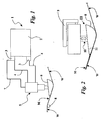
- Figure 1 schematically represents coating apparatus for possible use within the framework of
the invention,
- Figure 2 is an enlarged side elevational view of a coating device according to the invention,
and
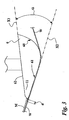
- Figure 3 is a further enlarged view of the portion of Figure 3 identified by arrow III, better
highlighting the geometry of the coating apparatus of the invention.
Detailed description of exemplary embodiments of the invention
-
Figure 1 shows the basic layout of coating apparatus 1 adapted for applying onto a
moving web W a layer M of a coating material.
-
An arrangement as shown in figure 1 may be applied, for instance, to the manufacture
of liquid impermeable, moisture vapour permeable layers obtained by coating a thermoplastic
composition onto a substrate. A suitable thermoplastic composition may comprise
thermoplastic polymers and suitable hydrophilic plasticisers that may also enhance the moisture
vapour permeability of films or layers made from the thermoplastic compositions. Such layers
can find a variety of applications wherein moisture vapour permeability is desirable, such as
within absorbent articles such as diapers, sanitary napkins, panty liners and the incontinence
products, and also protective bedding covers, protective clothing and the like. The substrate
being coated may be any kind of laminar substrate such as, for instance, a non-woven web of
the kind commonly used in the manufacture of the sanitary articles referred to in the foregoing.
-
A number of thermoplastic compositions particularly adapted for use in such a coating
process are disclosed, for instance, in WO-A-99/64077, WO-A-99/64505, WO-A-01/97870,
WO-A-01/98399, WO-A-02/14417, WO-A-02/28951.
-
In any case the scope and the spirit of the present invention is in no way limited to such
a prospected application.
-
In general terms, the coating material may be advantageously selected from the group
consisting of hot melt adhesives, while the web being coated is selected from the group
consisting of nonwowen materials, polymer films, and siliconised foil materials (paper/films).
-
Advantageously, the material of said web W is selected from the group consisting of
polyethylene (PE) and polypropylene (PP).
-
The coating material M is applied onto the web W in the fluid (that is, molten) state.
For that purpose, apparatus 1 generally includes a tank or reservoir 2 for containing the coating
material in the fluid state. One or more pumps 3 are provided for pumping the coating material
M from the reservoir 2 by means of sleeves or hoses 4 towards an applicator unit 5 including an
applicator head (or "gun") 6.
-
A return line or hose 7 is provided for re-circulating coating material not applied onto
the web W back towards one of the pumps 3 and/or the reservoir 2.
-
The coating material M is delivered from the applicator head or gun 6 through one or
more output nozzles 11, so as to be deposited onto the web W in the form of a substantially
continuous layer or line as a result of the relative movement of the web W being caused to
advance under the applicator head 6 (from right to left in figures 1 to 3).
-
To that end the web W is usually driven by means of a capstan roller 8 or the like
driven by a motor (not shown) and thus caused to slide under the applicator head 6.
-
In order to maintain the coating material M in the molten state, heating elements (of a
known type, not shown) are associated with the tank 2, the pumps 3, the delivery and return
lines 4 and 7, as well as the applicator unit 5 and, more specifically, the applicator head 6.
-
The arrangement considered in the foregoing is per se thoroughly conventional in the
art and does not require to be described in greater detail herein.
-
Figure 2 is an enlarged side elevational view of the applicator unit 5 that is usually
mounted onto a supporting element such as a bracket 9 included in the supporting framework
(not shown) of coating apparatus 1 in the vicinity of the drive roller 8.
-
In the presently preferred embodiment of the invention, the applicator head 6 is located
generally in the lower portion of the applicator unit 5. The web to be coated W is thus caused to
advance under the applicator unit 5 in sliding contact with the lower surface of the applicator
head 6. The applicator head 6 can be mounted on the applicator unit 5 by means of an
arrangement, such as telescopic arrangement 10. The applicator head 6 as a whole is thus
capable of moving, at least slightly, in the vertical direction (as shown by the double arrow in
figure 2) in order to allow for possible variations of the degree of longitudinal tension applied
to the web W. Alternatively, the whole applicator unit 5 can be capable of making said vertical
movement.
-
The applicator head 6 is usually in the form of a box or similar casing preferably having
a generally tapered profile that, in the presently preferred embodiment of the invention, is in the
form of a droplet-type or raindrop-type profile.
-
Essentially, the applicator head 6 is comprised of at least a partially hollow body
having flow lines for the coating material M extending therethrough and leading to one or more
outlet nozzles 11 generally located at the downstream end of the applicator head 6. The nozzle
or nozzles 11 can be in the form of e.g. slits or holes thus enabling the coating material M
expelled (extruded) therefrom to be in the form of a flat layer or lines.
-
As used herein, the "downstream" end of the (lower) surface of applicator head 6 is
intended to mean that end of the applicator head 6 that is located downstream of the applicator
head 6 itself with respect the relative movement of the web W to be coated, i.e. where the
output nozzle or nozzles 11 are located.
-
The relative movement of the web W with respect to the applicator head 6 is arranged
to take place in a application or coating region where the coating material M is actually applied
onto the web W by means of the nozzle or nozzles 11, while the web is kept in caused to follow
a rectilinear path, that is a path lying in a plane designated X2 (see figure 3).
-
The cross-sectional view of applicator head 6 is thus comprised of an "upstream" end
60 of a generally rounded shape at which the web W to be coated contacts the applicator head
6. Such generally rounded shape enables the web W to be, at least slightly, wrapped around the
upstream end 60 of the applicator head 6 to follow an at least marginally curved (i.e. concave)
trajectory while sliding against the applicator head 6.
A substantially flat intermediate portion 61 is provided in the outer surface of the
applicator head 6 such intermediate portion extending from the upstream end 60 of the
applicator head 6 towards the downstream end where the nozzles 11 are located. Such an
intermediate portion 61 of the surface of the applicator head 6 being flat allows the web W to
follow a substantially rectilinear trajectory, thereby taking on a generally flat shape in plane
X2, while being advanced towards and through the application or coating region where the
coating material M is ejected from the nozzle or nozzles 11.
-
As better appreciated in the enlarged view of figure 3, the flat intermediate surface 61
of the applicator head 6 and the web W are generally intended to be substantially co-planar
during the coating process.
While preserving such substantial co-planarity, the applicator head 6 is preferably
arranged with respect to the plane X2 in order to ensure that the nozzles 11, from which the
coating material M is extruded, do not exactly lie against the surface of the web W.
-
Preferably, the relative orientation of the web W and the applicator head 6 (i.e. the
nozzle or nozzles 11) is selected in such a way that in travelling from the nozzle or nozzles 11
to the surface the web W being coated, the coating material M follows a "free" path having
over a distance d. Typical values for d are in the range of 0 to 0.5 mm, preferably between 0
and 0.25 mm, and, in any case, less than 0.5 mm. The relative size of distance d in figure 3 has
been evidently exaggerated for the sake of illustration.
-
The coating material M is ejected from the nozzles 11 in a given direction X1 that, in
the exemplary embodiment shown in figures 2 and 3, roughly corresponds to the plane of the
upper, generally flat surface 62 of applicator head 6.
-
The general orientation of the direction X1 with the respect to the body of the
applicator head 6 can in any case be selectively varied by correspondingly modifying the
structure of the applicator head 6; such variations are within the ability of those of skill in the
art and, as such, do not require to be described in detail here.
-
An important feature of the arrangement of the invention lies in the relative orientation
of the direction or plane X1 where the coating material M is ejected (extruded) from the nozzle
or the nozzles 11 and the plane X2 where the portion of the web W being coated extends.
-
Experiments carried out by the Applicants indicate that the angle α formed between the
direction X1 and the direction X2 may be preferably less than 45°, preferably less than 30°, still
preferably less than 20°, the presently preferred value being less than 10°.
-
Again, the relative size of angle α in figure 3 has been evidently exaggerated for the
sake of illustration.
-
In connection with the coating of a substrate or web such as non-woven materials for
use in sanitary products coated with thermoplastic compositions, preferred ranges for the angle
α are between 0° and 30°, preferably between 0° and 20°, still preferably between 0° and 10°,
the presently preferred value being about 5°.
-
Of course, the quantitative data provided in the foregoing are to be construed by taking
into account the tolerances currently involved both in the implementation and in the
measurement of the respective values.
-
Experiments carried out by the Applicants indicate that by resorting to such an
arrangement, all the basic drawbacks of known processes wherein a molten composition is
extruded directly against a substrate being coated and actually pressed onto it by the extrusion
head are securely dispensed with. More to the point, especially in the presence of low viscosity
hot melt compositions, the arrangement shown herein safely avoids any impregnation in depth
of the substrate being coated by the coating material.
-
With the arrangement shown herein, low thickness coatings can be easily achieved, this
applying particularly to continuous coatings, that are important when breathable compositions
are used and are also intended to provide a liquid impervious barrier. Also, perforations usually
generated by the fibres comprised in a non-woven substrate in the known "contact" coating
methods, do not take place when e.g. hot melt layers are applied onto such a substrate by means
of the coating process disclosed herein. This results in improved layer or film formation,
particularly in terms of low thickness and uniformity/continuity of the coating.
-
Moreover, the specific geometry of the applicator head 6 shown in the drawings, leads
the applicator head 6 to act as a sliding shoe capable of exerting a pressure against the substrate
W before contact with the coating material (typically a hot melt composition) occurs. This
gives rise to a sort of "ironing" action exerted by the sliding shoe comprised in the applicator
head that stabilises the web before coating, also due to the relatively high temperature of the
applicator head itself.
-
Even without wishing to be bound to any specific theory in that respect, Applicants
have reason to believe that the unexpected results achieved by the arrangement of the present
invention are primarily related to the essentially "tangential" arrangement of the nozzle or
nozzles 11 with respect to the plane where the web W to be coated lies (i.e. direction X1 lying
within a small angular range with respect to the plane X2). Also, the coating material M coming
out of the nozzle or nozzles 11 and deposited on the surface of the web W in an essentially
unconstricted or unconfined manner ("free" path over the distance d in figure 3) is held to help
in achieving particularly satisfactory results. By unconstricted or unconfined manner a situation
is intended where the coating layer formed of material M is in no way urged or forced against
the web W being coated as a result of being extruded from the nozzle or nozzles 11 having a
distance d with respect to the surface of the web W to be coated. While avoiding the drawbacks
of the prior art arrangements, the solution shown herein does in no way adversely affect the
desired adhesion of the coating layer to the web W being coated.
-
Especially for non-woven substrates, the combination and the hold-down strength in the
adhesion of the coating layer to the substrate being coated may be possibly reinforced by
resorting to a conveyor with vacuum, thus achieving very smooth and delicate way of operation
without having to use e.g. rollers and the like.
-
The arrangement shown in the drawings is particularly adapted for producing materials
of the type disclosed in WO-A-99/64505 at a low basis weight (12.5-16 grams per square
meter), operating e.g. with a 200 millimetres coating width. Typical fluid pressure within the
applicator head or gun 6 is between 30 and 40 bar, with maximum pressure values around 70
bars, the temperature of coating material at the application point being around 200°C.
-
Of course, without prejudice to the principle of the invention, the details of
implementation and embodiments may be amply varied, also significantly, with respect to what
has been described and illustrated herein, by way of example only, without thereby departing
from the scope of the invention as defined in the annexed claims.