EP1468260B1 - Base construction for fibre-optic load sensors - Google Patents
Base construction for fibre-optic load sensors Download PDFInfo
- Publication number
- EP1468260B1 EP1468260B1 EP02767085A EP02767085A EP1468260B1 EP 1468260 B1 EP1468260 B1 EP 1468260B1 EP 02767085 A EP02767085 A EP 02767085A EP 02767085 A EP02767085 A EP 02767085A EP 1468260 B1 EP1468260 B1 EP 1468260B1
- Authority
- EP
- European Patent Office
- Prior art keywords
- optical fibre
- support
- rod
- shaped elements
- deformation structure
- Prior art date
- Legal status (The legal status is an assumption and is not a legal conclusion. Google has not performed a legal analysis and makes no representation as to the accuracy of the status listed.)
- Expired - Lifetime
Links
- 238000009411 base construction Methods 0.000 title claims abstract 9
- 239000000835 fiber Substances 0.000 claims abstract description 47
- 239000013307 optical fiber Substances 0.000 claims description 74
- 229920001971 elastomer Polymers 0.000 claims description 7
- 239000000806 elastomer Substances 0.000 claims description 7
- 230000003287 optical effect Effects 0.000 claims description 7
- 238000005452 bending Methods 0.000 claims description 6
- 239000000463 material Substances 0.000 claims 2
- 238000004519 manufacturing process Methods 0.000 abstract description 17
- 238000010276 construction Methods 0.000 abstract description 15
- 230000000737 periodic effect Effects 0.000 abstract 1
- 238000000926 separation method Methods 0.000 abstract 1
- 239000012535 impurity Substances 0.000 description 26
- 230000002452 interceptive effect Effects 0.000 description 18
- 230000035945 sensitivity Effects 0.000 description 13
- 238000013461 design Methods 0.000 description 7
- 230000008901 benefit Effects 0.000 description 6
- 238000000034 method Methods 0.000 description 6
- 230000008569 process Effects 0.000 description 6
- 230000007547 defect Effects 0.000 description 5
- 230000000694 effects Effects 0.000 description 4
- WYTGDNHDOZPMIW-RCBQFDQVSA-N alstonine Natural products C1=CC2=C3C=CC=CC3=NC2=C2N1C[C@H]1[C@H](C)OC=C(C(=O)OC)[C@H]1C2 WYTGDNHDOZPMIW-RCBQFDQVSA-N 0.000 description 3
- 241000881711 Acipenser sturio Species 0.000 description 2
- 238000013459 approach Methods 0.000 description 2
- 230000009286 beneficial effect Effects 0.000 description 2
- 238000001514 detection method Methods 0.000 description 2
- 229920001875 Ebonite Polymers 0.000 description 1
- 230000009471 action Effects 0.000 description 1
- 238000005266 casting Methods 0.000 description 1
- 230000008859 change Effects 0.000 description 1
- 238000005253 cladding Methods 0.000 description 1
- 230000006378 damage Effects 0.000 description 1
- 230000001419 dependent effect Effects 0.000 description 1
- 238000009826 distribution Methods 0.000 description 1
- 238000002474 experimental method Methods 0.000 description 1
- 230000001788 irregular Effects 0.000 description 1
- 239000007788 liquid Substances 0.000 description 1
- 239000011344 liquid material Substances 0.000 description 1
- 238000005036 potential barrier Methods 0.000 description 1
- 238000002360 preparation method Methods 0.000 description 1
- 230000002040 relaxant effect Effects 0.000 description 1
- 230000000087 stabilizing effect Effects 0.000 description 1
- 230000001629 suppression Effects 0.000 description 1
- 238000012360 testing method Methods 0.000 description 1
- 238000009827 uniform distribution Methods 0.000 description 1
Images


Classifications
-
- G—PHYSICS
- G01—MEASURING; TESTING
- G01L—MEASURING FORCE, STRESS, TORQUE, WORK, MECHANICAL POWER, MECHANICAL EFFICIENCY, OR FLUID PRESSURE
- G01L1/00—Measuring force or stress, in general
- G01L1/24—Measuring force or stress, in general by measuring variations of optical properties of material when it is stressed, e.g. by photoelastic stress analysis using infrared, visible light, ultraviolet
- G01L1/242—Measuring force or stress, in general by measuring variations of optical properties of material when it is stressed, e.g. by photoelastic stress analysis using infrared, visible light, ultraviolet the material being an optical fibre
- G01L1/243—Measuring force or stress, in general by measuring variations of optical properties of material when it is stressed, e.g. by photoelastic stress analysis using infrared, visible light, ultraviolet the material being an optical fibre using means for applying force perpendicular to the fibre axis
- G01L1/245—Measuring force or stress, in general by measuring variations of optical properties of material when it is stressed, e.g. by photoelastic stress analysis using infrared, visible light, ultraviolet the material being an optical fibre using means for applying force perpendicular to the fibre axis using microbending
Definitions
- the parallel course of the rod-shaped elements which is given both in a comb-shaped and in a rectangular support and interference structure, leads to a stretched fiber profile, which in turn is responsible for the lack of extensibility of the overall arrangement. It is also disadvantageous that the optical fiber can be displaced laterally even by small forces, in principle, no restoring force acts. However, the location of the fiber in some cases affects the sensitivity of the sensor and, in the case of local changes, the uniformity thereof. Remedy can be done by tilting the elements alternately by a certain angle. As a result, the meshes of the supporting and interfering structure basically change from a rectangular shape into a triangular shape.
Landscapes
- Physics & Mathematics (AREA)
- General Physics & Mathematics (AREA)
- Optical Transform (AREA)
- Light Guides In General And Applications Therefor (AREA)
- Measuring Fluid Pressure (AREA)
- Measuring Pulse, Heart Rate, Blood Pressure Or Blood Flow (AREA)
- Force Measurement Appropriate To Specific Purposes (AREA)
Abstract
Description
Belastungssensoren, die einen Druck von außen über den s.g. Microbending-Effekt einer Lichtleitfaser erfassen, weisen gegenüber solchen mit abweichenden Funktionsprinzipien attraktive Vorteile auf. Es sind eine ganze Reihe von Ausführungformen bekannt. Ihnen allen ist gemeinsam, daß durch den äußeren Druck die Lichtleitfaser gegen eine harte, unebene Störstruktur gepreßt wird, was eine Vielzahl kleiner Verformungen hervorruft, die wiederum zu einem signifikanten Anstieg der Faserdämpfung führen. Speist man folglich Licht in das eine Ende der Faser ein, so führt ein äußerer Druck zu einem Rückgang der an ihrem anderen Ende ankommenden Lichtleistung. Wenn der Sensor klug aufgebaut ist, genügt zum Nachweis dieses Leistungsrückgangs ein einfacher Photodetektor.Load sensors that exert an external pressure on the s.g. Capture the microbending effect of an optical fiber, have attractive advantages over those with different functional principles. There are a number of embodiments known. They all have in common that the optical fiber is pressed by the external pressure against a hard, uneven interference structure, which causes a variety of small deformations, which in turn lead to a significant increase in the fiber attenuation. Thus, when light is introduced into one end of the fiber, external pressure results in a decrease in light output arriving at its other end. If the sensor is well designed, a simple photodetector will suffice to prove this decrease in power.
Abgesehen von ausreichender Empfindlichkeit gibt es aber noch eine ganze Reihe weiterer Kriterien, von denen es abhängt, ob sich ein solcher Sensor in der Praxis bewährt oder nicht. So muß z.B. in vielen Fällen ein Aufbau gefordert werden, der für eine gewisse Dehnbarkeit sorgt. Das gilt nicht nur für Situationen, in denen eine gewaltsame Verformung des Sensors zu erwarten ist. Vielmehr können auch innere Spannungen, wie sie z.B. aufgrund von unterschiedlicher Temperaturausdehnung der einzelnen Komponenten im Betrieb immer auftreten, zu unangenehmen Effekten bis hin zur Zerstörung der empfindlichen Lichtleitfaser führen. Ein dehnbarer Aufbau ist ein wirksames Mittel, solche Spannungen klein zu halten. Konkret bedeutet das z.B., daß die Lichtleitfaser nicht gestreckt im Sensor verlaufen darf, damit Längenänderungen des Gesamtaufbaus ausgeglichen werden können.Apart from sufficient sensitivity, there are still a number of other criteria, on which it depends, whether such a sensor in practice or not. So, for example, In many cases, a structure are required, which ensures a certain elasticity. This does not only apply to situations in which a violent deformation of the sensor is to be expected. Rather, internal stresses, as e.g. always occur due to different temperature expansion of the individual components during operation, lead to unpleasant effects up to the destruction of the sensitive optical fiber. A stretchable construction is an effective means of keeping such stresses low. Specifically, this means, for example, that the optical fiber is not allowed to stretch in the sensor, so that changes in length of the overall structure can be compensated.
Ein weiterer wichtiger Aspekt ist die Homogenität der Sensorempfindlichkeit. Bei den meisten Anwendungen wird immer nur ein relativ kleiner Teil des Sensors belastet. Das Ausgangssignal darf nicht zu sehr davon abhängig sein, welcher Teil dies gerade ist. Das führt zu der Forderung, daß die Stellen, an denen die Lichtleitfaser verformt wird (Störstellen), möglichst kleine, gleiche Abstände voneinander haben und ihrerseits möglichst gleich beschaffen sein müssen.Another important aspect is the homogeneity of the sensor sensitivity. For most applications, only a relatively small part of the sensor is ever loaded. The output signal should not be too dependent on which part this is. This leads to the requirement that the points at which the optical fiber is deformed (impurities), as small as possible, equal distances from each other and in turn must be as equal as possible.
Äußerst wichtig ist weiterhin eine Eigenschaft, die sich mit der Eingangsimpedanz eines elektrischen Meßgeräts vergleichen läßt: Belastungssensoren gleich welcher Ausführung reagieren letztlich nicht auf eine Kraft, sondern auf eine Verformung. Legt man ein Gewicht frei auf einen solchen Sensor, so wird er mit diesem Gewicht belastet, unabhängig davon, wie stark er sich darunter verformt. Bei den meisten interessanten Anwendungen wird diese Situation jedoch nicht angetroffen, sondern das Gewicht ist noch an anderer Stelle elastisch abgestützt. Es kommt hier bei Verformung des Sensors zu einem regelrechten "Zusammenbrechen" der auf ihn einwirkenden Last. Der Weg, der erforderlich ist, um bei einer Lichtleitfaser einen Microbending-Effekt hervorzurufen, ist glücklicherweise nicht groß, dennoch dürfen ihm keine weiteren Strecken hinzugefügt werden. Das bedeutet, der Sensor muß so aufgebaut sein, daß die Lichtleitfaser alle Störstellen auch im unbelasteten Zustand stets zumindest berührt, besser noch mit einer wohldefinierten Kraft dagegen gepreßt wird. Letztere darf aber auch wieder nicht zu groß werden, denn dadurch steigt die optische Dämpfung des Sensors, und zwar (in dB gemessen) proportional zur Anzahl der Störstellen, die daher um so größer gemacht werden kann, je kleiner die Anpreßkraft ist. Praktisch läßt sich eine völlig kraftlose Berührung nicht realisieren, erst recht nicht bei einer Vielzahl von Störstellen gleichzeitig, sodaß immer eine gewisse Anpreßkraft erforderlich ist. Diese möglichst klein und dennoch ausreichend groß zu halten um überall eine Berührung sicherzustellen stellt eine nicht zu unterschätzende Schwierigkeit dar.Very important is still a property that can be compared with the input impedance of an electrical meter: load sensors of any design ultimately respond not to a force, but to a deformation. If you place a weight freely on such a sensor, it will be loaded with this weight, regardless of how much it deforms underneath. In most interesting applications, however, this situation is not encountered, but the weight is elastically supported elsewhere. It comes here at deformation of the sensor to a veritable "collapse" of the load acting on it. Fortunately, the path required to cause a microbending effect on an optical fiber is not large, yet no further stretches may be added to it. This means that the sensor must be constructed so that the optical fiber always touched all impurities, even in the unloaded state, at least, better still with a well-defined force is pressed against it. However, the latter must not become too large again, because this increases the optical attenuation of the sensor, measured in dB, proportional to the number of impurities, which can therefore be made larger the smaller the contact pressure. In practice, a completely powerless touch can not be realized, especially not with a variety of defects at the same time, so that always a certain contact pressure is required. Keeping them as small as possible and yet large enough to ensure contact everywhere is a difficult issue that should not be underestimated.
In innerem Zusammenhang bzw. Widerspruch mit den beiden letztgenannten Forderungen steht die Bestrebung, Belastungssensoren möglichst ausgedehnt gestalten zu können. Man verbessert die Homogenität der Empfindlichkeit durch eine hohe Dichte der Störstellen, da sich Unterschiede dann ausmitteln. Eine größere Sensorausdehnung kann man hingegen durch Verringerung der Störstellendichte erreichen, was umso leichter möglich ist, je kleiner die Unterschiede sind, die sich ausmitteln müssen. Man kann den Sensor ebenfalls größer gestalten, indem man die Anzahl der Störstellen bei gegebener Dichte erhöht. Dies wiederum gelingt umso leichter, je geringer die Dämpfungszunahme pro Störstelle ausfällt, mithin also, je kleiner die Anpreßkraft im unbelasteten Zustand gestaltet werden kann.In internal connection or contradiction with the latter two demands is the effort to make stress sensors as extensive as possible. The homogeneity of the sensitivity is improved by a high density of the impurities since differences are then eliminated. By contrast, a larger sensor expansion can be achieved by reducing the impurity density, which is all the more easily possible the smaller the differences that have to be averaged out. You can also make the sensor larger by increasing the number of impurities at a given density. This in turn succeeds the easier, the lower the increase in attenuation per point of failure fails, that is, the smaller the contact pressure in the unloaded state can be designed.
Man erkennt, daß die Erfüllbarkeit aller drei letztgenannten Forderungen letztlich auf größtmögliche Gleichförmigkeit der Störstellen im Verein mit möglichst guter Beherrschbarkeit einer kleinen Anpreßkraft im unbelasteten Zustand hinausläuft.It can be seen that the satisfiability of all three last-mentioned requirements ultimately results in the greatest possible uniformity of the impurities together with the best possible controllability of a small contact force in the unloaded state.
Um eine möglichst hohe Druckempfindlichkeit zu erzielen, die viele Anwendungen erst möglich macht, darf die Lichtleitfaser in unmittelbarer Umgebung der Störstellen nicht unterstützt sein; es müssen sich hier Hohlräume "unter" der Faser befinden in die hinein sie sich schon unter geringer Krafteinwirkung verformen kann. Andererseits besteht die Forderung, daß der Sensor sonst keine Hohlräume enthalten darf, denn diese müßten erst durch Verformung geschlossen werden, bevor die zu erfassende Last auf die Faser übertragen wird. Das heißt, es muß möglich sein, zur Übertragung der Last auf die Faser einen einseitigen Formschluß zwischen ihr und irgendeiner elastischen Struktur zu erzielen, in welch letztere dann die Last von außen eingeleitet werden kann. Einen Formschluß erreicht man am leichtesten durch einen Gießprozeß, bei dem sich ein Medium in flüssigem Zustand der gewünschten Form anpaßt und dann in dieser Form erstarrt oder aushärtet. Damit nun im vorliegenden Fall dieser Formschluß wie gefordert einseitig bleibt, muß es möglich sein, das flüssige Material irgendwie am Ausfüllen der notwendigen Hohlräume zu hindern, und zwar ohne daß dabei die Erfüllung der obigen Forderungen eingeschränkt wird. Das ist möglich, indem eine elastische, membranartige Struktur "über" die Lichtleitfaser gespannt wird. Dazu wiederum eignet sich nicht jeder Aufbau.In order to achieve the highest possible pressure sensitivity, which makes many applications possible, the optical fiber in the immediate vicinity of the impurities must not be supported; there must be cavities "under" the fiber into which they can deform even under little force. On the other hand, there is a requirement that the sensor may otherwise contain no cavities, because these would have to be closed by deformation before the load to be detected is transmitted to the fiber. That is, it must be possible to achieve a one-sided positive engagement between it and any elastic structure for transmitting the load to the fiber, in which latter then the load can be introduced from outside. A positive connection is most easily achieved by a casting process in which a medium in the liquid state adapts to the desired shape and then solidifies or cures in this form. Thus, in the present case, this form-fitting as required remains unilaterally, it must be possible to somehow prevent the liquid material from filling in the necessary cavities, without thereby limiting the fulfillment of the above requirements. This is possible by stretching an elastic, membrane-like structure "over" the optical fiber. In turn, not every structure is suitable for this purpose.
Weitere Aspekte betreffen die Herstellbarkeit des Belastungssensors. Er benötigt z.B. eine faseroptische Zuleitung, denn müßte man den optischen Sender nebst Empfänger direkt am Sensor d.h. am Meßort montieren, würde man sich dadurch vieler Vorteile der faseroptischen Ausführung begeben. Muß eine solche Zuleitung an den Sensorlichtleiter angespleißt werden, verkompliziert und verteuert das die Herstellung. Das gilt natürlich in besonderem Maße, falls sogar der Sensor selbst Spleißprozesse erforderlich macht. Am günstigsten ist es, wenn für Sensor und Zuleitung ein und dieselbe Lichtleitfaser verwendet werden kann, und da oft längere Zuleitungen erforderlich werden, ist es noch wesentlich günstiger, wenn die Herstellung unter Manipulation des mittleren Teils eines ausgedehnten Lichtleiters erfolgen kann, ohne daß dabei dessen Enden mit einbezogen werden müssen.Further aspects concern the manufacturability of the load sensor. He needs e.g. a fiber optic cable, because you would have the optical transmitter and receiver directly on the sensor. At the measuring site, one would thereby go through many advantages of the fiber optic design. If such a supply line has to be spliced to the sensor light guide, this complicates and makes more expensive the production. Of course, this is particularly true if even the sensor itself requires splicing processes. It is best if one and the same optical fiber can be used for sensor and supply line, and since often longer leads are required, it is still much cheaper if the production can be done under manipulation of the middle part of an extended light guide, without affecting its Ends need to be involved.
Aus dem Bedürfnis nach Gleichförmigkeit der Störstellen ergibt sich ein weiterer die Herstellung betreffender Aspekt: Nachdem die Lichtleitfaser - möglichst definiert - mit der Störstruktur kombiniert wurde, muß die entstandene Baugruppe weiterhin handhabbar sein, zumindest in dem Sinne, daß der Herstellungsprozeß rationell zu Ende geführt werden kann, ohne daß die wohldefinierte Anordnung von Faser und Störstruktur dabei beeinträchtigt wird. Ein gegebener Sensoraufbau ist folglich als um so vorteilhafter anzusehen, je einfacher sich eine solche wohldefinierte Anordnung herstellen läßt und je stabiler sie in sich ist.The need for uniformity of the impurities results in a further aspect relating to the production: After the optical fiber has been combined with the interfering structure-if possible-the resultant assembly must continue to be manageable, at least in the sense that the production process is completed efficiently can, without the well-defined arrangement of fiber and interference structure is affected. A given sensor design is therefore considered to be the more advantageous the simpler such a well-defined arrangement can be made and the more stable it is in itself.
Wichtig ist darüber hinaus noch, wie gut sich ein faseroptischer Belastungssensor in unterschiedlichen Stückzahlen herstellen läßt. Zur Optimierung seiner Eigenschaften ist es meist erforderlich, zunächst Einzelstücke testen zu können; es wäre äußerst ungünstig falls hierfür bereits umfangreiche Fertigungseinrichtungen benötigt würden. Überdies sind Anwender geneigt, erst dann größere Stückzahlen einzusetzen, wenn sich ein Pilotlos in der Praxis bewährt hat. Andererseits muß aber auch eine wirtschaftliche Fertigung in größeren Stückzahlen möglich sein, sonst scheitert die Markteinführung am zu hohen Endpreis. Die Herstellbarkeit eines Sensors sowohl in kleinen als auch in mittleren und großen Stückzahlen kann daher darüber entscheiden, ob er sich überhaupt einführen läßt oder nicht, und bei der Gestaltung seines Aufbaus ist das zu berücksichtigen.It is also important, how well a fiber optic load sensor can be produced in different quantities. To optimize its properties, it is usually necessary to be able to test individual pieces first; It would be extremely unfavorable if this already extensive production equipment would be needed. Moreover, users are inclined to use larger quantities only when a pilot lot has proven itself in practice. On the other hand, however, an economic production in larger quantities must be possible, otherwise the market launch fails due to the high final price. The manufacturability of a sensor in both small and medium and large quantities may therefore decide whether or not to introduce it at all, and it must be taken into account in the design of its structure.
Die Verfüllung dieser Anforderungen ist die Aufgabe der vorliegenden Erfindung. Ihr Gegenstand ist ein prinzipieller Aufbau für faseroptische Belastungssensoren, der sich in vielfältiger Weise ausgestalten und abwandeln läßt, wobei er unterschiedlichen Gewichtungen der Forderungen angepaßt werden kann.The backfilling of these requirements is the object of the present invention. Its object is a basic structure for fiber optic load sensors, which can be configured and modified in many ways, where it can be adapted to different weights of the requirements.
Ein Hinweis zur Lösung eines Teils der gestellten Aufgabe läßt sich der Schrift
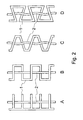
Dieser Lösungsansatz hat den Vorteil, daß der Abstand der Leitersprossen so bemessen werden kann, daß eine wellenförmige Verbiegung der Lichtleitfaser hervorgerufen wird, die sie mit wohldefinierter Anpreßkraft abwechselnd von oben und von unten gegen die Störstruktur drückt. Man erhält eine gleichmäßige Verteilung sehr gleichförmiger Störstellen, wobei die Anordnung aus Lichtleitfaser und Störstruktur zumindest in Längsrichtung eine völlig ausreichende Stabilität aufweist.This approach has the advantage that the distance of the ladder rungs can be dimensioned so that a wavy deflection of the optical fiber is caused, which presses them with a well-defined pressure force alternately from above and from below against the interference structure. This gives a uniform distribution of very uniform impurities, wherein the arrangement of optical fiber and interference structure has a completely sufficient stability at least in the longitudinal direction.
Der Aufbau aus
Die nahezu freie Beweglichkeit der Lichtleitfaser in seitlicher Richtung kann auch die Gleichförmigkeit der Sensorempfindlichkeit beeinträchtigen. Wird der Sensor nämlich z.B. in einer Nut montiert um etwa darüber hinwegfahrende Fahrzeuge zu detektieren, so liegt ein Fall vor, wo er systematisch in seiner Mitte stärker verformt wird als am Rand. Er ist dann umso unempfindlicher je weiter die Faser von der Mitte entfernt verläuft. Ein solcher außermittiger Verlauf der Faser kann sich aber während der Herstellung sehr leicht einstellen, wenn ihr eine seitliche Beweglichkeit eingeräumt wird.The nearly free movement of the optical fiber in the lateral direction can also affect the uniformity of the sensor sensitivity. If, for example, the sensor is mounted in a groove in order to detect vehicles passing over it, then it is obvious Case where it is systematically deformed more in the middle than at the edge. He is then the less sensitive the farther the fiber runs from the center. However, such eccentric course of the fiber can be adjusted very easily during the production, if it is given a lateral mobility.
Wohl der schwerwiegendste Nachteil einer leiterförmigen Stütz- und Störstruktur besteht darin, daß zum Aufbringen der Lichtleitfaser eines ihrer Enden durch sämtliche Zwischenräume geführt und die Faser dann jedesmal hindurchgezogen werden muß. Das Problem wird um so schwerwiegender, je länger der Sensor selbst und vor allem auch die freien Faserenden gemacht werden sollen. Für Anwendungen im Straßenverkehr werden kabelförmige Sensoren mit Längen um 3m eingesetzt; ihre Zuleitungskabel haben Längen von typisch 30m. Günstige Störstellenabstände liegen im Bereich um 10mm. Um einen Sensor für den Straßenverkehr in der genannten Weise herzustellen müßte die Faser also rund 300 mal zwischen den Sprossen hindurchgezogen werden; wollte man diesen Sensor unter Verwendung einer einzigen Faser ohne Spleiße herstellen, so gälte diese Aussage für ein Kabel von 30m Länge. Ein solcher Herstellungsprozeß ließe sich schwerlich rationell gestalten, ganz zu schweigen von der mechanischen Beanspruchung der Faser.Probably the most serious disadvantage of a ladder-shaped supporting and interfering structure is that for applying the optical fiber one of its ends is guided through all intermediate spaces and the fiber then has to be pulled through each time. The problem becomes all the more serious the longer the sensor itself and above all the free fiber ends are to be made. For road applications, cable sensors with lengths of around 3m are used; their supply cables have lengths of typically 30m. Cheap impurity spacings are in the range of 10mm. In order to produce a sensor for road traffic in the manner mentioned, the fiber would therefore have to be pulled through about 300 times between the rungs; If one wanted to make this sensor using a single fiber without splices, then this statement would apply to a cable of 30m length. Such a manufacturing process would be difficult to rationalize, let alone the mechanical stress of the fiber.
Aus der
In der Schrift
Die
Bei der vorliegenden Erfindung wird von einem alternierenden Faserverlauf wie in
Ausgehend von dem zunächst einfacheren Fall einer Leiterform lassen sich die geschlossenen Maschen am leichtesten durch Entfernung eines der "Leiterholme" öffnen (
Eine solche Rechteckform weist noch einen weiteren Vorteil auf: Beim Aufbringen der Lichtleitfaser auf eine kammförmige Stütz- und Störstruktur muß sie immer wieder über die Spitze des jeweils nächsten "Zahnes" geführt werden, um den alternierenden Verlauf zu realisieren. Bei diesem Vorgang besteht die Gefahr, daß sie über die Spitze des vorherigen "Zahnes" zurückgleitet, wodurch der alternierende Verlauf zumindest örtlich zerstört würde. Auf eine rechteckförmige Stütz- und Störstruktur wird die Faser hingegen dadurch aufgebracht, daß sie schraubenförmig um die Stütz- und Störstruktur herumgeführt wird. Beim Einführen in einen Zwischenraum kann sie aus dem vorhergehenden nicht herausgleiten, weil dieser in der betreffenden Richtung verschlossen ist. Die Faser kann überhaupt nur aus den beiden Zwischenräumen an den Enden der Stütz- und Störstruktur herausgleiten; bei allen anderen ist das wegen des Verschlusses der jeweilig angrenzenden Zwischenräume unmöglich. Eine Rechteckstruktur nach
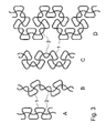
Der parallele Verlauf der stabförmigen Elemente, der sowohl bei einer kammförmigen als auch bei einer rechteckförmigen Stütz- und Störstruktur gegeben ist, führt zu einem gestreckten Faserverlauf, welch letzterer wiederum für die mangelnde Dehnbarkeit der Gesamtanordnung verantwortlich ist. Ebenso nachteilig ist, daß die Lichtleitfaser schon durch kleine Kräfte seitlich verschoben werden kann, wobei prinzipiell keine Rückstellkraft wirkt. Die Lage der Faser beeinflußt aber in bestimmten Fällen die Empfindlichkeit des Sensors und bei örtlichen Änderungen die Gleichförmigkeit derselben. Abhilfe läßt sich schaffen, indem man die Elemente abwechselnd um einen bestimmten Winkel neigt. Die Maschen der Stütz-und Störstruktur gehen dadurch von einer Rechteckform prinzipiell in eine Dreieckform über.The parallel course of the rod-shaped elements, which is given both in a comb-shaped and in a rectangular support and interference structure, leads to a stretched fiber profile, which in turn is responsible for the lack of extensibility of the overall arrangement. It is also disadvantageous that the optical fiber can be displaced laterally even by small forces, in principle, no restoring force acts. However, the location of the fiber in some cases affects the sensitivity of the sensor and, in the case of local changes, the uniformity thereof. Remedy can be done by tilting the elements alternately by a certain angle. As a result, the meshes of the supporting and interfering structure basically change from a rectangular shape into a triangular shape.
Um solche dreieckförmigen Maschen zu öffnen hat man die Wahl zwischen zwei Möglichkeiten, die in
Durch die abwechselnde Neigung der stabförmigen Elemente der Störstruktur wird bewirkt, daß sich die Lichtleitfaser bei mittiger Lage in einem energetischen Minimum befindet. Wird sie zur Seite ausgelenkt, so wird sie auch in mindestens eine "Ecke" gedrückt. Ihre Neigung gegen die Ebene der Stütz- und Störstruktur muß dann an dieser Stelle größer werden, was sowohl erhöhte Biegespannungen als auch einen Zug auf die angrenzenden Bereiche der Faser verursacht, dem sie wiederum nur durch stärkere Biegung an weiter entfernten Stellen nachgeben kann. Sie ist gleichsam bestrebt, zwischen Störstellen mit gleichen Abständen zu verlaufen, und solche existieren nur in der Mitte der Stütz-und Störstruktur. Dies resultiert in einer Kraft, die seitlichen Auslenkungen der Faser entgegenwirkt.The alternating inclination of the rod-shaped elements of the interfering structure causes the optical fiber is located in a central position in an energetic minimum. If it is deflected to the side, it is also pressed into at least one "corner". Its inclination against the plane of the support and interference structure must then be larger at this point, which causes both increased bending stresses and a train on the adjacent areas of the fiber, which in turn can yield only by stronger bending at more remote locations. It seeks, as it were, to run between impurities at equal intervals, and such exist only in the middle of the supporting and interfering structure. This results in a force that counteracts lateral deflections of the fiber.
Als Regel zur seitlichen Stabilisierung der Lichleitfaser kann daraus die Aussage abgeleitet werden, daß die stabförmigen Elemente, bzw. die Stellen über die die Faser verlaufen müßte. abseits des gewünschten Verlaufs keine gleichen Abstände haben dürfen. Eine Ausgestaltung der Stütz- und Störstruktur mit aufeinanderfolgenden parallelen stabförmigen Elementen wie sowohl in der
Aufgrund der genannten Rückstellkraft, die bei einem parallelen Verlauf der stabförmigen Elemente nicht vorhanden ist, kann der Faser nun ein leicht serpentinenförmiger Verlauf aufgezwungen werden (in
Die beiden Dreieckstrukturen in
Eine Stütz- und Störstruktur nach dem Prinzip von
Ein Aufbau nach
Durch einen Aufbau nach
Mit einem Aufbau nach
In einem solchen Fall ist es möglich, zwei nebeneinanderliegende Aufbauten nach
Auf jede der angegebenen Stütz- und Störstrukturen kann die Lichtleitfaser auch mehrfach aufgebracht werden. Dadurch erhöht sich nicht nur die Anzahl der Störstellen, es bietet sich z.B. auch die wichtige Möglichkeit, sie auf ihrem Weg durch die Stütz- und Störstruktur wieder zurückzuführen, um dadurch ihren Ein- und Austritt an der gleichen Stelle zu erhalten. Ebenso ist es dadurch möglich, mehrere unabhängige Lichtleitfasern durch ein und dieselbe Stütz- und Störstruktur zu führen, was einen redundanten Aufbau ergibt, der sowohl aus Gründen der Ausfallsicherheit als auch zur Rauschunterdrückung wünschenswert sein kann.On each of the specified supporting and interfering structures, the optical fiber can also be applied several times. Not only does this increase the number of defects, it also provides e.g. also the important possibility to return them on their way through the supporting and sturgeon structure, thereby preserving their entry and exit at the same place. Likewise, it is thereby possible to guide a plurality of independent optical fibers through one and the same support and interference structure, resulting in a redundant structure, which may be desirable for reasons of both reliability and for noise suppression.
Hierfür bieten sich mehrere Möglichkeiten, die Sensoren mit speziellen Eigenschaften ergeben.
Es ist auch möglich, zwei Lichtleitfasern nacheinander so aufzubringen, daß sie die Stütz- und Störstruktur auf jeweils der gleichen Seite kreuzen. Ein solcher Aufbau ist aber - abgesehen vom Herstellungsverfahren - äquivalent zu einem Aufbau nach
Ein Aufbau nach
In
Ein Aufbau nach
Die Stütz- und Störstruktur (1) des Aufbaus nach
Die Tatsache, daß die Stütz- und Störstruktur Reihen aus hintereinander angeordneten stabförmigen Elementen enthält, was normalerweise die Dehnbarkeit des Aufbaus beeinträchtigt, ist hier nicht kritisch. Zum einen sind diese Reihen maximal drei Elemente lang, zum anderen verlaufen sie diagonal zu den Hauptachsen des Sensors. Ist dieser nur einigermaßen langgestreckt, so ist es nahezu unmöglich, ihn unter 45° zu seiner langen Achse zu belasten, und Scherspannungen können Sensoren dieser Art aufgrund ihrer Biegsamkeit kaum aufnehmen.The fact that the support and interference structure contains rows of rod-shaped elements arranged one behind the other, which normally affects the ductility of the structure, is not critical here. First, these rows are a maximum of three elements long, on the other hand they run diagonally to the main axes of the sensor. If this is only slightly elongated, it is almost impossible to load it at 45 ° to its long axis, and shear stresses can hardly absorb sensors of this kind due to their flexibility.
Der beschriebene Prinzipaufbau eignet sich folglich sowohl für linienförmige als auch für flächige faseroptische Belastungssensoren. In keinem Fall ist bei ihrer Herstellung eine Manipulation der Faserenden notwendig. Linienförmige Ausgestaltungen können mit einer elastischen Umhüllung zur Steigerung der Druckempfindlichkeit auch bei Einbettung in relativ harte Elastomere umgeben werden. Bei flächigen Ausführungen läßt sich dies nur durch Verwendung weicherer Elastomere erreichen. Hierdurch und auch durch mehrfaches Aufbringen der Lichtleitfaser kann die Empfindlichkeit in weiten Grenzen variiert werden. Die hohe Stabilität des Aufbaus führt zu guter Reproduzierbarkeit und Gleichförmigkeit der Sensoreigenschaften.The described principle is therefore suitable for both linear and for surface fiber optic load sensors. In no case is a manipulation of the fiber ends necessary during their manufacture. Line-shaped embodiments can be surrounded with an elastic envelope to increase the pressure sensitivity even when embedded in relatively hard elastomers. In flat versions, this can only be achieved by using softer elastomers. As a result, and also by multiple application of the optical fiber, the sensitivity can be varied within wide limits. The high stability of the structure leads to good reproducibility and uniformity of the sensor properties.
Claims (7)
- Base construction for fibre optic load sensors comprising a support and deformation structure (1) and at least one optical fibre optical waveguide (2, 2a, 2b) having light entry and light exit ends, said load acting upon the optical fibre waveguide assembly and detected by light transmitted from the light entry end to the light exit end being affected by changes in the bending radius of the optical fibre forming said optical fibre waveguide assembly, characterized in that both the light entry and light exit ends are disposed outside said support and deformation structure, in that said support and deformation structure comprises hard rod-shaped elements accessible from all sides and disposed in a plane in a manner such that their cross-sections are equally spaced along at least one specific path through said plane but are not so spaced outside that path, and in that said optical fibre extends alternatingly abovbe and below the rod-shaped elements along the aforesaid path, with the aforesaid cross-sections of the rod-shaped elements being configured, and the equal distances between them being selected, so as to cause the wave-shaped bends of the optical fibres to ensure a low compressive force acting at all times between the optical fibre and the rod-shaped elements, and with said rod-shaped elements being interconnected in a quasi-rigid manner directly or by means of special connecting elements disposed outside the path along which the optical fibre extends and in such a manner that said rod-shaped elements and/or said connecting elements form neither closed meshes nor extended rectilinear structures composed of directly interconnected elements.
- Base construction for optical fibre load sensors as claimed in claim 1 in which both said rod-shaped elements and the quasi-rigid connecting elements are configured to form a common wire-shaped structure extending through said plane.
- Base construction for optical fibre load sensors as claimed in any one of claims 1 and 2 in which the supporting and deformation structure (1) and the optical fibre (2, 2a, 2b) are surrounded by a hollow resilient sheath (4) which snugly fits the optical fibre at sites where the latter intersects the rod-shaped elements of the support and deformation structure.
- Base construction for optical fibre load sensors as claimed in any one of claims 1 and 2 in which the support and deformation structure (1) and the optical fibre (2, 2a, 2b) are embedded in a body (3) consisting of an elastomer material.
- Base construction for optical fibre load sensors as claimed in claim 3 in which the support and deformation structure (1), the optical fibre (2, 2a, 2b) and the resilient sheath (4) are embedded in a body (3) consisting of an elastomer material.
- Base construction for optical fibre load sensors as claimed in any one of the foregoing claims in which a plurality of optical fibres (2a, 2b) extend side by side through the support and deformation structure (1).
- Base construction for fibre load load sensors as claimed in any one of claims 1 to 5 in which two optical fibres (2a, 2b) extend through said support and deformation structure in a manner such that in places where one of said optical fibres extends above one of said rod-shaped elements of the support and deformation structure the other optical fibre extends below the respective rod-shaped elements, and vice versa.
Applications Claiming Priority (3)
| Application Number | Priority Date | Filing Date | Title |
|---|---|---|---|
| DE10138023 | 2001-08-08 | ||
| DE10138023A DE10138023B4 (en) | 2001-08-08 | 2001-08-08 | Fiber optic load sensor |
| PCT/DE2002/002875 WO2003016954A2 (en) | 2001-08-08 | 2002-08-05 | Fibre-optic load sensor with complex support structure |
Publications (2)
| Publication Number | Publication Date |
|---|---|
| EP1468260A2 EP1468260A2 (en) | 2004-10-20 |
| EP1468260B1 true EP1468260B1 (en) | 2011-04-20 |
Family
ID=7694206
Family Applications (1)
| Application Number | Title | Priority Date | Filing Date |
|---|---|---|---|
| EP02767085A Expired - Lifetime EP1468260B1 (en) | 2001-08-08 | 2002-08-05 | Base construction for fibre-optic load sensors |
Country Status (5)
| Country | Link |
|---|---|
| EP (1) | EP1468260B1 (en) |
| AT (1) | ATE506608T1 (en) |
| DE (2) | DE10138023B4 (en) |
| ES (1) | ES2363213T3 (en) |
| WO (1) | WO2003016954A2 (en) |
Families Citing this family (4)
| Publication number | Priority date | Publication date | Assignee | Title |
|---|---|---|---|---|
| US20070037462A1 (en) * | 2005-05-27 | 2007-02-15 | Philbrick Allen | Optical fiber substrate useful as a sensor or illumination device component |
| CN103765017B (en) | 2011-07-15 | 2017-04-05 | 机械解析有限公司 | Actuator |
| CN106404242B (en) * | 2016-10-13 | 2022-01-14 | 浙江理工大学 | Smooth sense sensor based on optical fiber micro-bending effect |
| CN116839768B (en) * | 2023-06-30 | 2024-02-20 | 济南大学 | Miniature piezoresistive stress sensor based on tungsten diselenide |
Family Cites Families (7)
| Publication number | Priority date | Publication date | Assignee | Title |
|---|---|---|---|---|
| DE3234345A1 (en) * | 1982-09-16 | 1984-03-22 | Robert Bosch Gmbh, 7000 Stuttgart | CODING SYSTEM FOR DETECTING INFORMATION FROM WORKPIECE CARRIERS AND THE LIKE |
| CA1268640A (en) * | 1985-11-14 | 1990-05-08 | Battelle Development Corporation | Fiber-optical pressure detector |
| GB2204679A (en) * | 1987-04-30 | 1988-11-16 | Univ Manchester | Fibre optic sensor |
| US5193129A (en) * | 1991-09-27 | 1993-03-09 | Rockwell International Corporation | Pressure sensor utilizing microbending of a fiber optic cable woven through a ladder shaped structure |
| DE19534260C2 (en) * | 1995-09-15 | 2002-07-04 | Friedrich Motzko | Rope-shaped fiber optic load sensor |
| US5684912A (en) * | 1995-10-18 | 1997-11-04 | Fico, Inc. | Optical fiber signal attenuator |
| US5913245A (en) * | 1997-07-07 | 1999-06-15 | Grossman; Barry G. | Flexible optical fiber sensor tapes, systems and methods |
-
2001
- 2001-08-08 DE DE10138023A patent/DE10138023B4/en not_active Expired - Fee Related
-
2002
- 2002-08-05 AT AT02767085T patent/ATE506608T1/en active
- 2002-08-05 ES ES02767085T patent/ES2363213T3/en not_active Expired - Lifetime
- 2002-08-05 DE DE50215020T patent/DE50215020D1/en not_active Expired - Lifetime
- 2002-08-05 EP EP02767085A patent/EP1468260B1/en not_active Expired - Lifetime
- 2002-08-05 WO PCT/DE2002/002875 patent/WO2003016954A2/en active Application Filing
Also Published As
| Publication number | Publication date |
|---|---|
| ES2363213T3 (en) | 2011-07-27 |
| WO2003016954A2 (en) | 2003-02-27 |
| DE50215020D1 (en) | 2011-06-01 |
| EP1468260A2 (en) | 2004-10-20 |
| DE10138023B4 (en) | 2007-11-15 |
| ATE506608T1 (en) | 2011-05-15 |
| DE10138023A1 (en) | 2003-03-06 |
| WO2003016954A3 (en) | 2004-08-12 |
Similar Documents
| Publication | Publication Date | Title |
|---|---|---|
| EP0479839B1 (en) | Fibre-optic cable with at least one optical fibre | |
| DE10012291C1 (en) | Process for fiber optic temperature measurement and fiber optic temperature sensor | |
| DE2751058C2 (en) | ||
| AT412564B (en) | Anchoring for pre-tensioned and/or stressed tensile elements comprises a wedge and anchoring body formed by at least two wedge-shaped layers lying over each other | |
| DE19534260C1 (en) | Rope-shaped fiber optic load sensor | |
| EP0696782A1 (en) | Optical compressive force sensor | |
| DE3336794C2 (en) | Sheathed cord | |
| DE60014631T2 (en) | STRAIN MEASUREMENT | |
| DE3639703A1 (en) | TENSILE TABLE | |
| EP2063018A2 (en) | Temperature resistant, elastic thread element | |
| EP1468260B1 (en) | Base construction for fibre-optic load sensors | |
| DE2854419C2 (en) | ||
| DE2530009A1 (en) | BRAIDED TAPE WITH CABLE ELEMENTS | |
| DE1447995C3 (en) | Electromechanical converter with a piezo resistance element | |
| DE3012638C2 (en) | Fiber optic cable with means to enable location | |
| EP0840331A1 (en) | Flexible line | |
| DE102015214889A1 (en) | Cable and method for its production | |
| DE2709106C2 (en) | Optical cable | |
| DE1958300C3 (en) | Malleable reinforcement for structures | |
| DE2122008C3 (en) | Nuclear fuel assembly | |
| DE3821123C2 (en) | ||
| EP1332262B2 (en) | Reinforcing mat for reinforced concrete | |
| DE6918881U (en) | CAGE FOR RADIAL ROLLERS IN A ROLLER ROTATING CONNECTION | |
| DE2714275C2 (en) | ||
| DE3936168C2 (en) |
Legal Events
| Date | Code | Title | Description |
|---|---|---|---|
| PUAI | Public reference made under article 153(3) epc to a published international application that has entered the european phase |
Free format text: ORIGINAL CODE: 0009012 |
|
| 17P | Request for examination filed |
Effective date: 20040305 |
|
| AK | Designated contracting states |
Kind code of ref document: A2 Designated state(s): AT BE BG CH CY CZ DE DK EE ES FI FR GB GR IE IT LI LU MC NL PT SE SK TR |
|
| 17Q | First examination report despatched |
Effective date: 20080417 |
|
| GRAP | Despatch of communication of intention to grant a patent |
Free format text: ORIGINAL CODE: EPIDOSNIGR1 |
|
| GRAS | Grant fee paid |
Free format text: ORIGINAL CODE: EPIDOSNIGR3 |
|
| GRAA | (expected) grant |
Free format text: ORIGINAL CODE: 0009210 |
|
| AK | Designated contracting states |
Kind code of ref document: B1 Designated state(s): AT BE BG CH CY CZ DE DK EE ES FI FR GB GR IE IT LI LU MC NL PT SE SK TR |
|
| REG | Reference to a national code |
Ref country code: GB Ref legal event code: FG4D Free format text: NOT ENGLISH |
|
| REG | Reference to a national code |
Ref country code: CH Ref legal event code: EP |
|
| REG | Reference to a national code |
Ref country code: IE Ref legal event code: FG4D Free format text: LANGUAGE OF EP DOCUMENT: GERMAN |
|
| REF | Corresponds to: |
Ref document number: 50215020 Country of ref document: DE Date of ref document: 20110601 Kind code of ref document: P |
|
| REG | Reference to a national code |
Ref country code: DE Ref legal event code: R096 Ref document number: 50215020 Country of ref document: DE Effective date: 20110601 |
|
| REG | Reference to a national code |
Ref country code: ES Ref legal event code: FG2A Ref document number: 2363213 Country of ref document: ES Kind code of ref document: T3 Effective date: 20110727 |
|
| REG | Reference to a national code |
Ref country code: NL Ref legal event code: VDEP Effective date: 20110420 |
|
| PG25 | Lapsed in a contracting state [announced via postgrant information from national office to epo] |
Ref country code: PT Free format text: LAPSE BECAUSE OF FAILURE TO SUBMIT A TRANSLATION OF THE DESCRIPTION OR TO PAY THE FEE WITHIN THE PRESCRIBED TIME-LIMIT Effective date: 20110822 Ref country code: SE Free format text: LAPSE BECAUSE OF FAILURE TO SUBMIT A TRANSLATION OF THE DESCRIPTION OR TO PAY THE FEE WITHIN THE PRESCRIBED TIME-LIMIT Effective date: 20110420 |
|
| REG | Reference to a national code |
Ref country code: IE Ref legal event code: FD4D |
|
| PG25 | Lapsed in a contracting state [announced via postgrant information from national office to epo] |
Ref country code: CY Free format text: LAPSE BECAUSE OF FAILURE TO SUBMIT A TRANSLATION OF THE DESCRIPTION OR TO PAY THE FEE WITHIN THE PRESCRIBED TIME-LIMIT Effective date: 20110420 Ref country code: FI Free format text: LAPSE BECAUSE OF FAILURE TO SUBMIT A TRANSLATION OF THE DESCRIPTION OR TO PAY THE FEE WITHIN THE PRESCRIBED TIME-LIMIT Effective date: 20110420 Ref country code: GR Free format text: LAPSE BECAUSE OF FAILURE TO SUBMIT A TRANSLATION OF THE DESCRIPTION OR TO PAY THE FEE WITHIN THE PRESCRIBED TIME-LIMIT Effective date: 20110721 |
|
| PG25 | Lapsed in a contracting state [announced via postgrant information from national office to epo] |
Ref country code: NL Free format text: LAPSE BECAUSE OF FAILURE TO SUBMIT A TRANSLATION OF THE DESCRIPTION OR TO PAY THE FEE WITHIN THE PRESCRIBED TIME-LIMIT Effective date: 20110420 |
|
| PG25 | Lapsed in a contracting state [announced via postgrant information from national office to epo] |
Ref country code: EE Free format text: LAPSE BECAUSE OF FAILURE TO SUBMIT A TRANSLATION OF THE DESCRIPTION OR TO PAY THE FEE WITHIN THE PRESCRIBED TIME-LIMIT Effective date: 20110420 Ref country code: IE Free format text: LAPSE BECAUSE OF FAILURE TO SUBMIT A TRANSLATION OF THE DESCRIPTION OR TO PAY THE FEE WITHIN THE PRESCRIBED TIME-LIMIT Effective date: 20110420 Ref country code: CZ Free format text: LAPSE BECAUSE OF FAILURE TO SUBMIT A TRANSLATION OF THE DESCRIPTION OR TO PAY THE FEE WITHIN THE PRESCRIBED TIME-LIMIT Effective date: 20110420 |
|
| PLBE | No opposition filed within time limit |
Free format text: ORIGINAL CODE: 0009261 |
|
| STAA | Information on the status of an ep patent application or granted ep patent |
Free format text: STATUS: NO OPPOSITION FILED WITHIN TIME LIMIT |
|
| BERE | Be: lapsed |
Owner name: SENSOR LINE G.M.B.H. Effective date: 20110831 |
|
| PG25 | Lapsed in a contracting state [announced via postgrant information from national office to epo] |
Ref country code: SK Free format text: LAPSE BECAUSE OF FAILURE TO SUBMIT A TRANSLATION OF THE DESCRIPTION OR TO PAY THE FEE WITHIN THE PRESCRIBED TIME-LIMIT Effective date: 20110420 Ref country code: DK Free format text: LAPSE BECAUSE OF FAILURE TO SUBMIT A TRANSLATION OF THE DESCRIPTION OR TO PAY THE FEE WITHIN THE PRESCRIBED TIME-LIMIT Effective date: 20110420 |
|
| 26N | No opposition filed |
Effective date: 20120123 |
|
| PG25 | Lapsed in a contracting state [announced via postgrant information from national office to epo] |
Ref country code: MC Free format text: LAPSE BECAUSE OF NON-PAYMENT OF DUE FEES Effective date: 20110831 |
|
| REG | Reference to a national code |
Ref country code: CH Ref legal event code: PL |
|
| GBPC | Gb: european patent ceased through non-payment of renewal fee |
Effective date: 20110805 |
|
| PG25 | Lapsed in a contracting state [announced via postgrant information from national office to epo] |
Ref country code: CH Free format text: LAPSE BECAUSE OF NON-PAYMENT OF DUE FEES Effective date: 20110831 Ref country code: LI Free format text: LAPSE BECAUSE OF NON-PAYMENT OF DUE FEES Effective date: 20110831 |
|
| REG | Reference to a national code |
Ref country code: DE Ref legal event code: R097 Ref document number: 50215020 Country of ref document: DE Effective date: 20120123 |
|
| PG25 | Lapsed in a contracting state [announced via postgrant information from national office to epo] |
Ref country code: BE Free format text: LAPSE BECAUSE OF NON-PAYMENT OF DUE FEES Effective date: 20110831 Ref country code: IT Free format text: LAPSE BECAUSE OF FAILURE TO SUBMIT A TRANSLATION OF THE DESCRIPTION OR TO PAY THE FEE WITHIN THE PRESCRIBED TIME-LIMIT Effective date: 20110420 |
|
| PG25 | Lapsed in a contracting state [announced via postgrant information from national office to epo] |
Ref country code: GB Free format text: LAPSE BECAUSE OF NON-PAYMENT OF DUE FEES Effective date: 20110805 |
|
| PGFP | Annual fee paid to national office [announced via postgrant information from national office to epo] |
Ref country code: FR Payment date: 20120921 Year of fee payment: 11 Ref country code: ES Payment date: 20120824 Year of fee payment: 11 |
|
| PGFP | Annual fee paid to national office [announced via postgrant information from national office to epo] |
Ref country code: AT Payment date: 20120810 Year of fee payment: 11 |
|
| PG25 | Lapsed in a contracting state [announced via postgrant information from national office to epo] |
Ref country code: LU Free format text: LAPSE BECAUSE OF NON-PAYMENT OF DUE FEES Effective date: 20110805 |
|
| PG25 | Lapsed in a contracting state [announced via postgrant information from national office to epo] |
Ref country code: BG Free format text: LAPSE BECAUSE OF FAILURE TO SUBMIT A TRANSLATION OF THE DESCRIPTION OR TO PAY THE FEE WITHIN THE PRESCRIBED TIME-LIMIT Effective date: 20110720 |
|
| PG25 | Lapsed in a contracting state [announced via postgrant information from national office to epo] |
Ref country code: TR Free format text: LAPSE BECAUSE OF FAILURE TO SUBMIT A TRANSLATION OF THE DESCRIPTION OR TO PAY THE FEE WITHIN THE PRESCRIBED TIME-LIMIT Effective date: 20110420 |
|
| REG | Reference to a national code |
Ref country code: AT Ref legal event code: MM01 Ref document number: 506608 Country of ref document: AT Kind code of ref document: T Effective date: 20130805 |
|
| REG | Reference to a national code |
Ref country code: FR Ref legal event code: ST Effective date: 20140430 |
|
| PG25 | Lapsed in a contracting state [announced via postgrant information from national office to epo] |
Ref country code: AT Free format text: LAPSE BECAUSE OF NON-PAYMENT OF DUE FEES Effective date: 20130805 |
|
| PG25 | Lapsed in a contracting state [announced via postgrant information from national office to epo] |
Ref country code: FR Free format text: LAPSE BECAUSE OF NON-PAYMENT OF DUE FEES Effective date: 20130902 |
|
| REG | Reference to a national code |
Ref country code: ES Ref legal event code: FD2A Effective date: 20140905 |
|
| PG25 | Lapsed in a contracting state [announced via postgrant information from national office to epo] |
Ref country code: ES Free format text: LAPSE BECAUSE OF NON-PAYMENT OF DUE FEES Effective date: 20130806 |
|
| PGFP | Annual fee paid to national office [announced via postgrant information from national office to epo] |
Ref country code: DE Payment date: 20190829 Year of fee payment: 18 |
|
| REG | Reference to a national code |
Ref country code: DE Ref legal event code: R119 Ref document number: 50215020 Country of ref document: DE |
|
| PG25 | Lapsed in a contracting state [announced via postgrant information from national office to epo] |
Ref country code: DE Free format text: LAPSE BECAUSE OF NON-PAYMENT OF DUE FEES Effective date: 20210302 |