EP1468190B1 - Liquid cooled electric driven rotordynamic system - Google Patents
Liquid cooled electric driven rotordynamic system Download PDFInfo
- Publication number
- EP1468190B1 EP1468190B1 EP03708836A EP03708836A EP1468190B1 EP 1468190 B1 EP1468190 B1 EP 1468190B1 EP 03708836 A EP03708836 A EP 03708836A EP 03708836 A EP03708836 A EP 03708836A EP 1468190 B1 EP1468190 B1 EP 1468190B1
- Authority
- EP
- European Patent Office
- Prior art keywords
- rotordynamic
- recited
- motor
- hollow shaft
- rotordynamic system
- Prior art date
- Legal status (The legal status is an assumption and is not a legal conclusion. Google has not performed a legal analysis and makes no representation as to the accuracy of the status listed.)
- Expired - Lifetime
Links
Images

Classifications
-
- F—MECHANICAL ENGINEERING; LIGHTING; HEATING; WEAPONS; BLASTING
- F04—POSITIVE - DISPLACEMENT MACHINES FOR LIQUIDS; PUMPS FOR LIQUIDS OR ELASTIC FLUIDS
- F04B—POSITIVE-DISPLACEMENT MACHINES FOR LIQUIDS; PUMPS
- F04B35/00—Piston pumps specially adapted for elastic fluids and characterised by the driving means to their working members, or by combination with, or adaptation to, specific driving engines or motors, not otherwise provided for
- F04B35/04—Piston pumps specially adapted for elastic fluids and characterised by the driving means to their working members, or by combination with, or adaptation to, specific driving engines or motors, not otherwise provided for the means being electric
-
- F—MECHANICAL ENGINEERING; LIGHTING; HEATING; WEAPONS; BLASTING
- F04—POSITIVE - DISPLACEMENT MACHINES FOR LIQUIDS; PUMPS FOR LIQUIDS OR ELASTIC FLUIDS
- F04D—NON-POSITIVE-DISPLACEMENT PUMPS
- F04D13/00—Pumping installations or systems
- F04D13/02—Units comprising pumps and their driving means
- F04D13/06—Units comprising pumps and their driving means the pump being electrically driven
-
- F—MECHANICAL ENGINEERING; LIGHTING; HEATING; WEAPONS; BLASTING
- F04—POSITIVE - DISPLACEMENT MACHINES FOR LIQUIDS; PUMPS FOR LIQUIDS OR ELASTIC FLUIDS
- F04D—NON-POSITIVE-DISPLACEMENT PUMPS
- F04D25/00—Pumping installations or systems
- F04D25/02—Units comprising pumps and their driving means
- F04D25/06—Units comprising pumps and their driving means the pump being electrically driven
-
- F—MECHANICAL ENGINEERING; LIGHTING; HEATING; WEAPONS; BLASTING
- F04—POSITIVE - DISPLACEMENT MACHINES FOR LIQUIDS; PUMPS FOR LIQUIDS OR ELASTIC FLUIDS
- F04D—NON-POSITIVE-DISPLACEMENT PUMPS
- F04D29/00—Details, component parts, or accessories
- F04D29/58—Cooling; Heating; Diminishing heat transfer
- F04D29/5806—Cooling the drive system
-
- F—MECHANICAL ENGINEERING; LIGHTING; HEATING; WEAPONS; BLASTING
- F04—POSITIVE - DISPLACEMENT MACHINES FOR LIQUIDS; PUMPS FOR LIQUIDS OR ELASTIC FLUIDS
- F04D—NON-POSITIVE-DISPLACEMENT PUMPS
- F04D29/00—Details, component parts, or accessories
- F04D29/58—Cooling; Heating; Diminishing heat transfer
- F04D29/5813—Cooling the control unit
-
- H—ELECTRICITY
- H02—GENERATION; CONVERSION OR DISTRIBUTION OF ELECTRIC POWER
- H02K—DYNAMO-ELECTRIC MACHINES
- H02K11/00—Structural association of dynamo-electric machines with electric components or with devices for shielding, monitoring or protection
- H02K11/30—Structural association with control circuits or drive circuits
- H02K11/33—Drive circuits, e.g. power electronics
-
- H—ELECTRICITY
- H02—GENERATION; CONVERSION OR DISTRIBUTION OF ELECTRIC POWER
- H02K—DYNAMO-ELECTRIC MACHINES
- H02K9/00—Arrangements for cooling or ventilating
- H02K9/19—Arrangements for cooling or ventilating for machines with closed casing and closed-circuit cooling using a liquid cooling medium, e.g. oil
-
- F—MECHANICAL ENGINEERING; LIGHTING; HEATING; WEAPONS; BLASTING
- F05—INDEXING SCHEMES RELATING TO ENGINES OR PUMPS IN VARIOUS SUBCLASSES OF CLASSES F01-F04
- F05D—INDEXING SCHEME FOR ASPECTS RELATING TO NON-POSITIVE-DISPLACEMENT MACHINES OR ENGINES, GAS-TURBINES OR JET-PROPULSION PLANTS
- F05D2240/00—Components
- F05D2240/60—Shafts
- F05D2240/61—Hollow
-
- H—ELECTRICITY
- H02—GENERATION; CONVERSION OR DISTRIBUTION OF ELECTRIC POWER
- H02K—DYNAMO-ELECTRIC MACHINES
- H02K7/00—Arrangements for handling mechanical energy structurally associated with dynamo-electric machines, e.g. structural association with mechanical driving motors or auxiliary dynamo-electric machines
- H02K7/14—Structural association with mechanical loads, e.g. with hand-held machine tools or fans
-
- Y—GENERAL TAGGING OF NEW TECHNOLOGICAL DEVELOPMENTS; GENERAL TAGGING OF CROSS-SECTIONAL TECHNOLOGIES SPANNING OVER SEVERAL SECTIONS OF THE IPC; TECHNICAL SUBJECTS COVERED BY FORMER USPC CROSS-REFERENCE ART COLLECTIONS [XRACs] AND DIGESTS
- Y10—TECHNICAL SUBJECTS COVERED BY FORMER USPC
- Y10T—TECHNICAL SUBJECTS COVERED BY FORMER US CLASSIFICATION
- Y10T29/00—Metal working
- Y10T29/49—Method of mechanical manufacture
- Y10T29/49826—Assembling or joining
Definitions
- the present invention relates to a rotordynamic system, and more particularly to a vertically arranged liquid cooled rotordynamic and motor/generator station.
- Industrial pump and compressor systems are common in processed fluid and gas industries such as hydrocarbon and chemical processing, pulp and paper, water treatment, power generation, and sanitary processing industries worldwide.
- Pump and compressor systems typically include a multiple of rather large dispersed components.
- One type of pump and compressor system having multiple stages is driven by an electric motor to produce high pressure at relatively low flows.
- Other systems utilize a speed increasing gearbox.
- the multiple stages and/or gearbox allows the usage of a relatively large air cooled motors which operate at a relatively low speed of approximately 3000-3600 rpm.
- multiple stages and/or gearboxes may result in added complexity, reduced reliability and a rather large system.
- the large air cooled motor is typically relatively noisy during operation.
- variable speed drive is relatively complex and must be protected from the environmental conditions adjacent the pump.
- the variable speed drive is therefore remotely located from the pump or compressor in a separate environmentally controlled room.
- a separate remotely located controller monitors and controls the disbursed system components. Although providing a rather significant practical speed range, the disbursed system complicates installation.
- EP-A-0831236 discloses a pump with a cooled frequency converter.
- the frequency converter is mounted on top of the pump motor and acts as a heat sink for components of the frequency converter.
- the plate is cooled by a cooling medium.
- US-A-4651897 discloses a pump mounted on a vertical support.
- a pressure sensor which controls operation of the pump motor is mounted at an upper part of the pump.
- the preferred rotordynamic system disclosed herein provides a base mounting a vertical support.
- a motor, a rotordynamic device and a controller are mounted to the vertical support such that a compact, small footprint system is provided.
- the motor is mounted in a substantially vertical relationship along the vertical support.
- the rotordynamic device is a centrifugal pump or compressor operated by the motor to drive a fluid from the input to the output, however, a power recovery turbine driving a generator will also benefit from the present invention.
- a liquid cooling system operates to maintain the controller and motor at a desired operating temperature.
- the liquid cooling system is in heat exchange relationship with an oil system contained within the motor to distribute thermal energy therebetween to further increase thermal control of each.
- the motor is thereby operable through practically any speed range.
- the motor includes a hollow shaft which serves as a "dynamic oil pump.” Oil flow from an oil sump is induced in the hollow shaft due to rotation and the passage of vapor through radial feed apertures at the top of the shaft. As the oil rises in the shaft, it removes the thermal energy caused by slip of the induction rotor. The radial feed apertures at the top of the shaft throws cooling fluid out into the multiple passages to direct cooling fluid toward the motor housing on the outside of the stator. The passages are oriented and sized to prevent oil from entering the air gap between the rotor and stator. The oil then flows down under the influence of gravity over a set of cooling coils and drains back into the sump. The coils communicate with the liquid cooling system which is arranged in a heat exchange relationship with the gravity assisted liquid return. Thermal energy within the motor is used to provide preheating of the controller and thereby minimize condensation formation and other environmental irregularities.
- the present invention therefore provides in its preferred embodiment an integrated rotordynamic system having a practically unlimited speed range within a small easily transportable package.
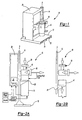
- FIG. 1 illustrates a general perspective view of a rotordynamic system 10.
- the rotordynamic system 10 generally includes a base 12 mounting a vertical support 14 which defines an axis A.
- a motor 16, a rotordynamic device 18 and a controller 20 are mounted to the vertical support 14 such that a compact, small footprint system 10 is provided.
- the base 12 includes a plurality of longitudinal members 22 which define a multiple of slots 24 to receive a forklift or the like and thereby assist in transport of the system 10.
- the vertical support 14 forms a box-like structure for connection to a crane or the like and further assists in conveyance of the system 10.
- the motor 16 is mounted in a substantially vertical relationship along the vertical support 14. That is, the motor 16 is mounted parallel to axis A and substantially perpendicular to the base 12.
- a movable mount 26 attaches the motor 16 to the vertical support for movement parallel to axis A. Movement of the mount 26 along the vertical support provides for the motor 16 to be separable from the rotordynamic device 18 ( Figure 2B ).
- the mount 26 may be moved along the vertical support 14 by a conventional pulley, ratchet, chain, or the like then locked into one of a plurality of positions. Maintenance of the motor 16 is thereby simplified and the rotordynamic device 18 need not be disconnected from its inputs and outputs (illustrated schematically at 28, and 30).
- the rotordynamic device 18 is mounted to the vertical support 14 opposite the base 12. That is, the rotordynamic device 18 is mounted above the motor 16 relative to the base 12.
- the rotordynamic device 18 is preferably a centrifugal pump or compressor operated by the motor 16 to drive a fluid from the input 28 to the output 30, however, a power recovery turbine driving a generator will also benefit from the present invention. In the power recovery turbine driven generator application, the input and outputs would be reversed as parenthetically illustrated in Figure 2A .
- the controller 20 operates the motor 16 through any speed range, though preferably through a range of 2000 to 100,000 revolutions per minute.
- the controller 20 is a power electronic system which includes a variable frequency drive as is generally known.
- the controller 20 is mounted to the vertical support 14 opposite the motor 16 to provide a counterbalance therefor.
- a liquid cooling system (illustrated schematically at 32) operates to maintain the controller 20 and motor 16 at a desired operating temperature.
- the output 30 may additionally be utilized to provide cooling fluid to the motor 16 and/or controller 20.
- the liquid cooling system 32 may operate with separate cooling fluids or may be a single integrated cooling circuit.
- the liquid cooling system 32 is in heat exchange relationship with an oil system ( Figure 3A ) contained within the motor 16 to distribute thermal energy therebetween to further increase thermal control of each. Such thermal transfer is well within the art of cooling system design.
- a gravity assisted liquid return 38 ( Figure 3C ) is preferably mounted within the motor housing 40.
- the gravity assisted liquid return 38 includes a sump 42 at the lowest portion of the motor housing 40 adjacent the base 12 ( Figure 1 ).
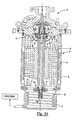
- the motor 16 includes a hollow shaft 44 mounted for rotation within radial bearings 46a, 46b.
- the bearings 46a, 46b preferably have a generally cylindrical bore with a subtle triangular shape (tri-lobe) for rotational stability.
- the shaft 44 rotatably mounts a rotor 34 within a fixed stator 36.
- Axial vanes 48 are located within the hollow shaft at the sump 42 end of the shaft 44 to augment oil flow into the shaft 44.
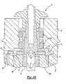
- the shaft end 50 opposite the sump 42 includes a multiple of radial feed apertures 52 which communicate oil to a thrust disc 54 mounted within a seal housing 55 ( Figure 3B ).
- the radial feed apertures 52 provide exits for the oil and vapors from the sump 42 and preferably communicate oil through a multiple of thrust disc radial feed apertures 53.
- the radial feed apertures 52 communicate with a housing annulus 57 which communicates with a multiple of passages 56.
- Bearings 46a, 46b are fed pressurized oil from via the radial feed apertures 52 in the hollow shaft 44.
- the thrust disc 54 is mounted adjacent the radial bearing 46b for fluid and vapor extraction through a multiple of passages 56 located through the seal housing 55 adjacent to the outer periphery of the thrust disc 54 ( Figure 3B ).
- a bearing annulus 61 is preferably formed in an upper surface of bearing 46b. Bearing annulus 61 communicates with passages 56 to collect oil and provide for start-up lubrication of thrust disc 54.
- the combined annulus 57, 61 collect oil such that the rotating components are provided with an immediate source of lubrication during start-up. Longevity of the components is thereby increased as friction from heretofore start-up lubrication deficiency is substantially avoided.
- passages 56 are arranged and direct oil flow outward toward the housing 40 ( Figure 3C ).
- Seals 59 are mounted about the rotordynamic device shaft 60 to prevent oil from entering into the rotordynamic device 18.
- An oil slinger 62 is mounted to the shaft 44 adjacent the bearing 46b and opposite the thrust disc 54.
- the slinger 62 is preferably, frustro-conical or cup like with an open end 63 facing the bearing 46b to collect oil therein during spin down of the shaft 44.
- the hollow shaft 44 serves as the "dynamic oil pump.” Oil flow (oil flow illustrated schematically by arrows f) from the sump 42 is induced in the hollow shaft 44 due to rotation and the passage of vapor through the radial feed apertures 52 at the top of the shaft 44. Oil from the sump 42 enters the shaft 44 and rises up in a thin layer to a vertical height dependent on the speed of rotation.
- the axial vanes 48 located at the lower shaft end augment the oil flow at higher speeds approximately greater than 6000. As the oil rises in the shaft, it removes the thermal energy caused by slip of the induction rotor.
- the radial feed apertures 52 ( Figure 3B ) at the end 50 of the shaft 44 throws cooling fluid out into the multiple passages 56 located in the seal housing 55 adjacent the outer periphery of the thrust disc 54.
- the passages 56 direct cooling fluid toward the motor housing 40 on the outside of the stator 36.
- the passages 56 are preferably oriented and sized to direct oil from entering the air gap between the rotor 34 and stator 36. The oil then flows down under the influence of gravity over a set of cooling coils 58 and drains into the sump 42. Another set of cooling coils 60 are additionally or in the alternatively located in the sump 42.
- the coils 58, 60 preferably communicate with the liquid cooling system 32 ( Figure 2A ) which is arranged in a heat exchange relationship with the gravity assisted liquid return 38. Thermal energy within the oil flow within the motor 16 is used to provide preheating of the controller 20 ( Figure 2A ) and thereby minimize condensation formation and other environmental irregularities.
- Cooling fluid discharged from bearing 46b which does not have sufficient velocity to reach the motor housing 40 is collected in the open end 63 of the oil slinger 62 to prevent cooling fluid from entering the air gap between the rotor 34 and stator 36.
- the slinger 62 fills with oil to provide immediate lubrication for the bearings 46a, 46b during the next start-up.
Landscapes
- Engineering & Computer Science (AREA)
- Mechanical Engineering (AREA)
- General Engineering & Computer Science (AREA)
- Physics & Mathematics (AREA)
- Thermal Sciences (AREA)
- Power Engineering (AREA)
- Microelectronics & Electronic Packaging (AREA)
- Motor Or Generator Cooling System (AREA)
- Details Of Reciprocating Pumps (AREA)
- Compressors, Vaccum Pumps And Other Relevant Systems (AREA)
- Connection Of Motors, Electrical Generators, Mechanical Devices, And The Like (AREA)
Description
- The present invention relates to a rotordynamic system, and more particularly to a vertically arranged liquid cooled rotordynamic and motor/generator station.
- Industrial pump and compressor systems are common in processed fluid and gas industries such as hydrocarbon and chemical processing, pulp and paper, water treatment, power generation, and sanitary processing industries worldwide.
- Conventional pump and compressor systems typically include a multiple of rather large dispersed components. One type of pump and compressor system having multiple stages is driven by an electric motor to produce high pressure at relatively low flows. Other systems utilize a speed increasing gearbox. The multiple stages and/or gearbox allows the usage of a relatively large air cooled motors which operate at a relatively low speed of approximately 3000-3600 rpm. Disadvantageously, multiple stages and/or gearboxes may result in added complexity, reduced reliability and a rather large system. Moreover, the large air cooled motor is typically relatively noisy during operation.
- Other types of conventional pump and compressor systems utilize a variable speed drive. The variable speed drive is relatively complex and must be protected from the environmental conditions adjacent the pump. The variable speed drive is therefore remotely located from the pump or compressor in a separate environmentally controlled room. A separate remotely located controller monitors and controls the disbursed system components. Although providing a rather significant practical speed range, the disbursed system complicates installation.
- Accordingly, it is desirable to provide an integrated rotordynamic system having a practically unlimited speed range within a small easily transportable package.
-
EP-A-0831236 discloses a pump with a cooled frequency converter. The frequency converter is mounted on top of the pump motor and acts as a heat sink for components of the frequency converter. The plate is cooled by a cooling medium. -
US-A-4651897 discloses a pump mounted on a vertical support. A pressure sensor which controls operation of the pump motor is mounted at an upper part of the pump. - According to the invention there is provided a rotordynamic system as claimed in claim 1.
- The preferred rotordynamic system disclosed herein provides a base mounting a vertical support. A motor, a rotordynamic device and a controller are mounted to the vertical support such that a compact, small footprint system is provided. The motor is mounted in a substantially vertical relationship along the vertical support. The rotordynamic device is a centrifugal pump or compressor operated by the motor to drive a fluid from the input to the output, however, a power recovery turbine driving a generator will also benefit from the present invention.
- A liquid cooling system operates to maintain the controller and motor at a desired operating temperature. The liquid cooling system is in heat exchange relationship with an oil system contained within the motor to distribute thermal energy therebetween to further increase thermal control of each. The motor is thereby operable through practically any speed range.
- The motor includes a hollow shaft which serves as a "dynamic oil pump." Oil flow from an oil sump is induced in the hollow shaft due to rotation and the passage of vapor through radial feed apertures at the top of the shaft. As the oil rises in the shaft, it removes the thermal energy caused by slip of the induction rotor. The radial feed apertures at the top of the shaft throws cooling fluid out into the multiple passages to direct cooling fluid toward the motor housing on the outside of the stator. The passages are oriented and sized to prevent oil from entering the air gap between the rotor and stator. The oil then flows down under the influence of gravity over a set of cooling coils and drains back into the sump. The coils communicate with the liquid cooling system which is arranged in a heat exchange relationship with the gravity assisted liquid return. Thermal energy within the motor is used to provide preheating of the controller and thereby minimize condensation formation and other environmental irregularities.
- The present invention therefore provides in its preferred embodiment an integrated rotordynamic system having a practically unlimited speed range within a small easily transportable package.
- The various features and advantages of this invention will become apparent to those skilled in the art from the following detailed description of the currently preferred embodiment. The drawings that accompany the detailed description can be briefly described as follows:
-
Figure 1 is a general perspective view of a rotordynamic system according to the present invention; -
Figure 2A is a schematic view of a rotordynamic system illustrated inFigure 1 in an operational position; -
Figure 2B is a schematic view of a rotordynamic system illustrated inFigure 1 in a maintenance position; -
Figure 3A is a partial sectional view of a motor of the rotordynamic system according to the present invention; -
Figure 3B is an exploded view of the motor illustrated inFigure 3A ; and -
Figure 3C is a partial sectional view of a motor schematically illustrating a gravity assisted oil flow path. -
Figure 1 illustrates a general perspective view of arotordynamic system 10. Therotordynamic system 10 generally includes abase 12 mounting avertical support 14 which defines an axis A. Amotor 16, arotordynamic device 18 and acontroller 20 are mounted to thevertical support 14 such that a compact,small footprint system 10 is provided. Thebase 12 includes a plurality oflongitudinal members 22 which define a multiple ofslots 24 to receive a forklift or the like and thereby assist in transport of thesystem 10. Thevertical support 14 forms a box-like structure for connection to a crane or the like and further assists in conveyance of thesystem 10. - Referring to
Figure 2A , themotor 16 is mounted in a substantially vertical relationship along thevertical support 14. That is, themotor 16 is mounted parallel to axis A and substantially perpendicular to thebase 12. - A
movable mount 26 attaches themotor 16 to the vertical support for movement parallel to axis A. Movement of themount 26 along the vertical support provides for themotor 16 to be separable from the rotordynamic device 18 (Figure 2B ). Themount 26 may be moved along thevertical support 14 by a conventional pulley, ratchet, chain, or the like then locked into one of a plurality of positions. Maintenance of themotor 16 is thereby simplified and therotordynamic device 18 need not be disconnected from its inputs and outputs (illustrated schematically at 28, and 30). - The
rotordynamic device 18 is mounted to thevertical support 14 opposite thebase 12. That is, therotordynamic device 18 is mounted above themotor 16 relative to thebase 12. Therotordynamic device 18 is preferably a centrifugal pump or compressor operated by themotor 16 to drive a fluid from theinput 28 to theoutput 30, however, a power recovery turbine driving a generator will also benefit from the present invention. In the power recovery turbine driven generator application, the input and outputs would be reversed as parenthetically illustrated inFigure 2A . - The
controller 20 operates themotor 16 through any speed range, though preferably through a range of 2000 to 100,000 revolutions per minute. Thecontroller 20 is a power electronic system which includes a variable frequency drive as is generally known. Thecontroller 20 is mounted to thevertical support 14 opposite themotor 16 to provide a counterbalance therefor. - A liquid cooling system (illustrated schematically at 32) operates to maintain the
controller 20 andmotor 16 at a desired operating temperature. Theoutput 30 may additionally be utilized to provide cooling fluid to themotor 16 and/orcontroller 20. Theliquid cooling system 32 may operate with separate cooling fluids or may be a single integrated cooling circuit. Preferably, theliquid cooling system 32 is in heat exchange relationship with an oil system (Figure 3A ) contained within themotor 16 to distribute thermal energy therebetween to further increase thermal control of each. Such thermal transfer is well within the art of cooling system design. - Referring to
Figure 3A , a sectional view of themotor 16 mounted to therotordynamic device 18 is illustrated. As themotor 16 is vertically oriented, a gravity assisted liquid return 38 (Figure 3C ) is preferably mounted within themotor housing 40. The gravity assistedliquid return 38 includes asump 42 at the lowest portion of themotor housing 40 adjacent the base 12 (Figure 1 ). - The
motor 16 includes ahollow shaft 44 mounted for rotation withinradial bearings bearings shaft 44 rotatably mounts arotor 34 within a fixedstator 36. Axial vanes 48 are located within the hollow shaft at thesump 42 end of theshaft 44 to augment oil flow into theshaft 44. The shaft end 50 opposite thesump 42 includes a multiple ofradial feed apertures 52 which communicate oil to athrust disc 54 mounted within a seal housing 55 (Figure 3B ). Theradial feed apertures 52 provide exits for the oil and vapors from thesump 42 and preferably communicate oil through a multiple of thrust discradial feed apertures 53. Theradial feed apertures 52 communicate with ahousing annulus 57 which communicates with a multiple ofpassages 56.Bearings radial feed apertures 52 in thehollow shaft 44. - The
thrust disc 54 is mounted adjacent theradial bearing 46b for fluid and vapor extraction through a multiple ofpassages 56 located through theseal housing 55 adjacent to the outer periphery of the thrust disc 54 (Figure 3B ). A bearingannulus 61 is preferably formed in an upper surface of bearing 46b. Bearingannulus 61 communicates withpassages 56 to collect oil and provide for start-up lubrication ofthrust disc 54. The combinedannulus passages 56 are arranged and direct oil flow outward toward the housing 40 (Figure 3C ).Seals 59 are mounted about therotordynamic device shaft 60 to prevent oil from entering into therotordynamic device 18. - An oil slinger 62 is mounted to the
shaft 44 adjacent thebearing 46b and opposite thethrust disc 54. The slinger 62 is preferably, frustro-conical or cup like with an open end 63 facing the bearing 46b to collect oil therein during spin down of theshaft 44. - Referring to
Figure 3C , thehollow shaft 44 serves as the "dynamic oil pump." Oil flow (oil flow illustrated schematically by arrows f) from thesump 42 is induced in thehollow shaft 44 due to rotation and the passage of vapor through theradial feed apertures 52 at the top of theshaft 44. Oil from thesump 42 enters theshaft 44 and rises up in a thin layer to a vertical height dependent on the speed of rotation. The axial vanes 48 located at the lower shaft end augment the oil flow at higher speeds approximately greater than 6000. As the oil rises in the shaft, it removes the thermal energy caused by slip of the induction rotor. - The radial feed apertures 52 (
Figure 3B ) at the end 50 of theshaft 44 throws cooling fluid out into themultiple passages 56 located in theseal housing 55 adjacent the outer periphery of thethrust disc 54. Thepassages 56 direct cooling fluid toward themotor housing 40 on the outside of thestator 36. Thepassages 56 are preferably oriented and sized to direct oil from entering the air gap between therotor 34 andstator 36. The oil then flows down under the influence of gravity over a set of cooling coils 58 and drains into thesump 42. Another set of cooling coils 60 are additionally or in the alternatively located in thesump 42. Thecoils Figure 2A ) which is arranged in a heat exchange relationship with the gravity assistedliquid return 38. Thermal energy within the oil flow within themotor 16 is used to provide preheating of the controller 20 (Figure 2A ) and thereby minimize condensation formation and other environmental irregularities. - Cooling fluid discharged from bearing 46b which does not have sufficient velocity to reach the
motor housing 40 is collected in the open end 63 of the oil slinger 62 to prevent cooling fluid from entering the air gap between therotor 34 andstator 36. Duringshaft 44 spin down, the slinger 62 fills with oil to provide immediate lubrication for thebearings - The foregoing description is exemplary rather than defined by the limitations within. Many modifications and variations of the present invention are possible in light of the above teachings. The preferred embodiments of this invention have been disclosed, however, one of ordinary skill in the art would recognize that certain modifications would come within the scope of this invention. It is, therefore, to be understood that within the scope of the appended claims, the invention may be practiced otherwise than as specifically described.
Claims (25)
- A rotordynamic system (10) comprising:a base (12);a vertical support (14) mounted to said base (12);a motor (16) mounted in a substantially vertical relationship to one side of said vertical support (14);a rotordynamic device (18) mounted in a substantially vertical relationship along said vertical support (14), said motor (16) operable to drive said rotordynamic device (18);a controller (20) operable to control said motor (16), said controller (20) mounted to said vertical support (14) opposite said motor (16) to provide a counter balance for said motor (16); anda liquid cooling system (32) operable to extract heat from said controller (20).
- The rotordynamic system as recited in claim 1, wherein said motor (16) is mounted adjacent said base (12) and said rotordynamic device (18) is mounted to said motor (16) opposite said base (12).
- The rotordynamic system as recited in any preceding claim, wherein said liquid cooling system (32) is m heat exchange relationship with a gravity assisted liquid return (38) within said motor (16).
- The rotordynamic system as recited in claim 3, wherein said gravity assisted liquid return (38) comprises a hollow shaft (44).
- The rotordynamic system as recited in claim 4, wherein said hollow shaft (44) comprises a plurality of axial vanes (48) adjacent an inlet of said hollow shaft (44).
- The rotordynamic system as recited in claim 3, wherein said a gravity assisted liquid return (38) comprises an oil slinger (62).
- The rotordynamic system as recited in any preceding claim, wherein said liquid cooling system (32) comprises a cooling coil located within said motor (16).
- The rotordynamic system as recited in any preceding claim, further comprising a movable mount attached to said motor and said vertical support, said movable mount movable along said vertical mount.
- The rotordynamic system as recited in any preceding claim, wherein said rotordynamic device (18) comprises a centrifugal pump.
- The rotordynamic system as recited in any of claims 1 to 8, wherein said rotordynamic device (18) comprises a compressor.
- The rotordynamic system as recited in any of claims 1 to 8, wherein said rotordynamic device (18) comprises a power recovery turbine.
- The rotordynamic system as recited in claim 11, wherein said motor (18) comprises a generator.
- The rotordynamic system as recited in any preceding claim, wherein said motor (16) comprises a hollow shaft (44) mounted within a bearing (46a, 46b), said bearing defining a bearing annulus adjacent a thrust disc (54), said bearing annulus operable to retain a quantity of a lubricant.
- The rotordynamic system as recited in claim 13, wherein said bearing annulus is substantially perpendicular to said hollow shaft (44).
- The rotordynamic system as recited in claim 13 or 14, wherein a multiple of radial feed apertures (52) in communication with said hollow shaft (44) communicate oil to said thrust disc (54).
- The rotordynamic system as recited in claim 13 or 14, further comprising a multiple of thrust disc radial feed apertures (52) in communication with said hollow shaft (44), said multiple of thrust disc radial feed apertures (52) in communication with a housing annulus operable to retain a quantity of a lubricant.
- The rotordynamic system as recited in claim 1, wherein:said rotordynamic device (18) is mounted to said motor (16); andsaid liquid cooling system (32) is operable to extract heat from said motor (16) and said controller (20).
- The rotordynamic system as recited in claim 17, wherein said motor (16) is mounted adjacent said base (12) and said rotordynamic device (18) is mounted to said motor (16) opposite said base (12).
- The rotordynamic system as recited in claim 17 or 18, wherein said liquid cooling system (32) is in heat exchange relationship with a gravity assisted liquid return (38) within said motor (16).
- The rotordynamic system as recited in claim 19, wherein said gravity assisted liquid return (38) comprises a hollow shaft (44).
- The rotordynamic system as recited in claim 20, wherein said hollow shaft (44) comprises a plurality of axial vanes (48) therein.
- The rotordynamic system as recited in claim 19, 20 or 21, wherein said a gravity assisted liquid return (38) comprises a cup-shaped oil slinger (62).
- The rotordynamic system as recited in any of claims 17 to 22, wherein said liquid cooling system (32) comprises a cooling coil (60) located within a sump (42).
- The rotordynamic system as recited in any of claims 17 to 23, wherein said liquid cooling system (32) comprises a cooling coil (58) located about a motor stator (36).
- The rotordynamic system as recited in claim 24, wherein said a gravity assisted liquid return (38) communicates with said cooling coil (58) located about a motor stator (36).
Applications Claiming Priority (3)
| Application Number | Priority Date | Filing Date | Title |
|---|---|---|---|
| US10/056,902 US6685447B2 (en) | 2002-01-25 | 2002-01-25 | Liquid cooled integrated rotordynamic motor/generator station with sealed power electronic controls |
| US56902 | 2002-01-25 | ||
| PCT/US2003/001279 WO2003064861A1 (en) | 2002-01-25 | 2003-01-16 | Liquid cooled electric driven rotordynamic system |
Publications (2)
| Publication Number | Publication Date |
|---|---|
| EP1468190A1 EP1468190A1 (en) | 2004-10-20 |
| EP1468190B1 true EP1468190B1 (en) | 2010-09-08 |
Family
ID=27609342
Family Applications (1)
| Application Number | Title | Priority Date | Filing Date |
|---|---|---|---|
| EP03708836A Expired - Lifetime EP1468190B1 (en) | 2002-01-25 | 2003-01-16 | Liquid cooled electric driven rotordynamic system |
Country Status (7)
| Country | Link |
|---|---|
| US (1) | US6685447B2 (en) |
| EP (1) | EP1468190B1 (en) |
| JP (1) | JP4302529B2 (en) |
| CN (1) | CN100394039C (en) |
| CA (1) | CA2473807C (en) |
| DE (1) | DE60334065D1 (en) |
| WO (1) | WO2003064861A1 (en) |
Families Citing this family (30)
| Publication number | Priority date | Publication date | Assignee | Title |
|---|---|---|---|---|
| US9261104B2 (en) * | 2005-09-19 | 2016-02-16 | Ingersoll-Rand Company | Air blower for a motor-driven compressor |
| ITMI20060294A1 (en) * | 2006-02-17 | 2007-08-18 | Nuovo Pignone Spa | MOTOCOMPRESSORE |
| US9214842B2 (en) * | 2007-02-07 | 2015-12-15 | Regal Beloit America, Inc. | Motor |
| ITMI20072428A1 (en) * | 2007-12-24 | 2009-06-25 | Gianfranco Bianchi | GENERATOR GROUP WITH OIL COOLING |
| BE1019030A5 (en) | 2009-08-03 | 2012-01-10 | Atlas Copco Airpower Nv | TURBO COMPRESSOR SYSTEM. |
| US8525375B2 (en) * | 2010-03-23 | 2013-09-03 | Hamilton Sundstrand Corporation | Cooling arrangement for end turns and stator in an electric machine |
| US8435016B2 (en) | 2010-11-10 | 2013-05-07 | Hamilton Sundstrand Corporation | Vertical shaft pumping system with lubricant impeller arrangement |
| US9300190B2 (en) * | 2011-10-21 | 2016-03-29 | Hamilton Sundstrand Corporation | Free-surface liquid capture device for rotating machinery |
| US8872361B2 (en) | 2012-01-25 | 2014-10-28 | Briggs & Stratton Corporation | Standby generators including compressed fiberglass components |
| US8970075B2 (en) * | 2012-08-08 | 2015-03-03 | Ac Propulsion, Inc. | Liquid cooled electric motor |
| US9013879B2 (en) | 2012-12-04 | 2015-04-21 | Hamilton Sundstrand Corporation | Electronic component cooling hood and heat pipe |
| EP2950429B1 (en) * | 2013-01-25 | 2021-03-10 | Daikin Industries, Ltd. | Fluid device |
| EP3218606B1 (en) | 2014-11-13 | 2019-02-13 | Caprari S.p.A. | Electric pump with closed loop cooling system |
| DE102016111408A1 (en) * | 2016-06-22 | 2017-12-28 | Xylem Ip Management Sàrl | Pumping device for conveying a fluid |
| DE102016111445A1 (en) * | 2016-06-22 | 2017-12-28 | Xylem Ip Management Sàrl | Pumping device for conveying a fluid |
| CN107546890B (en) | 2016-06-28 | 2021-07-16 | 特灵国际有限公司 | Harmonic shunting motor, method, AC motor system and variable speed driving system |
| JP6756382B2 (en) * | 2017-01-25 | 2020-09-16 | 株式会社Ihi | Electric compressor |
| US10826357B2 (en) | 2017-06-28 | 2020-11-03 | Trane International Inc. | Harmonic shunting electric motor with faceted shaft for improved torque transmission |
| CA3073853C (en) * | 2017-09-25 | 2023-02-28 | St9 Gas And Oil, Llc | Electric drive pump for well stimulation |
| US10784750B2 (en) * | 2018-06-12 | 2020-09-22 | General Electric Company | Electric motor having an integrated cooling system and methods of cooling an electric motor |
| US11245307B2 (en) | 2019-05-23 | 2022-02-08 | Hamilton Sundstrand Corporation | Electric motor assembly |
| US20200392960A1 (en) * | 2019-06-17 | 2020-12-17 | Ceco Environmental Ip Inc. | Turbine pumps |
| CN112483430B (en) * | 2019-09-12 | 2025-10-21 | 开利公司 | Centrifugal compressors and refrigeration units |
| CN112483429B (en) | 2019-09-12 | 2025-08-26 | 开利公司 | Centrifugal compressors and refrigeration units |
| US11705779B2 (en) | 2020-06-03 | 2023-07-18 | Briggs & Stratton, Llc | Inverter generator |
| US11591977B2 (en) | 2020-06-03 | 2023-02-28 | Briggs & Stratton, Llc | Inverter generator |
| CN115603491A (en) * | 2021-07-08 | 2023-01-13 | 青岛海尔智能技术研发有限公司(Cn) | Vertical rotor cooling structure, motor and compressor |
| CN115929667A (en) * | 2023-01-13 | 2023-04-07 | 安玖丰(苏州)环境工程有限责任公司 | Zero-leakage motor-driven self-cooling system based on isotope water vapor compressor |
| CN116104784A (en) * | 2023-01-13 | 2023-05-12 | 安玖丰(苏州)环境工程有限责任公司 | Isotope water vapor compressor equipment with zero-leakage motor self-cooling function |
| WO2025238671A1 (en) | 2024-05-15 | 2025-11-20 | Caprari S.P.A. | Electric pump |
Citations (1)
| Publication number | Priority date | Publication date | Assignee | Title |
|---|---|---|---|---|
| US4651897A (en) * | 1984-10-22 | 1987-03-24 | Sashco, Inc. | Portable progressive cavity pump |
Family Cites Families (19)
| Publication number | Priority date | Publication date | Assignee | Title |
|---|---|---|---|---|
| DE3642729C3 (en) | 1986-12-13 | 1997-05-07 | Grundfos Int | Pump unit for conveying liquids or gases |
| CN1005348B (en) * | 1987-03-23 | 1989-10-04 | 核工业部第二研究设计院 | Canned motor pump |
| JPH0241744U (en) * | 1988-09-13 | 1990-03-22 | ||
| US5443368A (en) | 1993-07-16 | 1995-08-22 | Helix Technology Corporation | Turbomolecular pump with valves and integrated electronic controls |
| JPH0750854Y2 (en) * | 1990-07-13 | 1995-11-15 | 株式会社荏原製作所 | Structure of pump mounting part of canned submersible motor for deep well pump |
| DE4121430C1 (en) * | 1991-06-28 | 1992-11-05 | Grundfos International A/S, Bjerringbro, Dk | |
| JP2501055B2 (en) * | 1991-11-21 | 1996-05-29 | 日機装株式会社 | How to increase the motor pressure in the motor pump |
| JPH0783189A (en) * | 1993-09-17 | 1995-03-28 | Hitachi Ltd | Turbo vacuum pump |
| JP3077490B2 (en) | 1993-12-28 | 2000-08-14 | 株式会社荏原製作所 | Pump assembly |
| ES2140715T3 (en) * | 1994-11-07 | 2000-03-01 | Hobourn Automotive Ltd | ROTARY PUMP AND MOTOR ASSEMBLY. |
| JP3327317B2 (en) | 1995-10-09 | 2002-09-24 | 株式会社荏原製作所 | Inverter water cooling |
| US5894273A (en) | 1996-08-26 | 1999-04-13 | Fairway Medical Technologies, Inc. | Centrifugal blood pump driver apparatus |
| DE19639098A1 (en) | 1996-09-24 | 1998-03-26 | Wilo Gmbh | Motor pump with cooled frequency converter |
| EP1243757B1 (en) | 1997-07-25 | 2005-12-07 | ALSTOM Technology Ltd | Process for operating a power plant |
| DE19736889C1 (en) | 1997-08-25 | 1999-02-11 | Siemens Ag | Operating method for combined gas-and-steam turbine plant |
| JPH11324996A (en) | 1998-05-11 | 1999-11-26 | Hitachi Ltd | Pump device |
| US6464464B2 (en) | 1999-03-24 | 2002-10-15 | Itt Manufacturing Enterprises, Inc. | Apparatus and method for controlling a pump system |
| JP2001114705A (en) * | 1999-10-12 | 2001-04-24 | Nippon Shokubai Co Ltd | Method for easily transporting polymerizable compound |
| US6447269B1 (en) * | 2000-12-15 | 2002-09-10 | Sota Corporation | Potable water pump |
-
2002
- 2002-01-25 US US10/056,902 patent/US6685447B2/en not_active Expired - Lifetime
-
2003
- 2003-01-16 CN CNB038027704A patent/CN100394039C/en not_active Expired - Fee Related
- 2003-01-16 JP JP2003564433A patent/JP4302529B2/en not_active Expired - Fee Related
- 2003-01-16 WO PCT/US2003/001279 patent/WO2003064861A1/en not_active Ceased
- 2003-01-16 CA CA002473807A patent/CA2473807C/en not_active Expired - Lifetime
- 2003-01-16 EP EP03708836A patent/EP1468190B1/en not_active Expired - Lifetime
- 2003-01-16 DE DE60334065T patent/DE60334065D1/en not_active Expired - Lifetime
Patent Citations (1)
| Publication number | Priority date | Publication date | Assignee | Title |
|---|---|---|---|---|
| US4651897A (en) * | 1984-10-22 | 1987-03-24 | Sashco, Inc. | Portable progressive cavity pump |
Also Published As
| Publication number | Publication date |
|---|---|
| CN100394039C (en) | 2008-06-11 |
| CN1623039A (en) | 2005-06-01 |
| JP2005516571A (en) | 2005-06-02 |
| JP4302529B2 (en) | 2009-07-29 |
| US20030143093A1 (en) | 2003-07-31 |
| US6685447B2 (en) | 2004-02-03 |
| WO2003064861A1 (en) | 2003-08-07 |
| EP1468190A1 (en) | 2004-10-20 |
| CA2473807A1 (en) | 2003-08-07 |
| CA2473807C (en) | 2010-01-12 |
| DE60334065D1 (en) | 2010-10-21 |
Similar Documents
| Publication | Publication Date | Title |
|---|---|---|
| CA2473807C (en) | Liquid cooled electric driven rotordynamic system | |
| US6379127B1 (en) | Submersible motor with shaft seals | |
| JP3240139B2 (en) | Windage reduction array for scroll fluid devices. | |
| CA2617657C (en) | Pressurized bearing system for submersible motor | |
| JPS58500448A (en) | Closed turbine generator | |
| US20140124172A1 (en) | Cooled flywheel apparatus | |
| EP0675287B1 (en) | Oil shield | |
| US6254361B1 (en) | Shaftless canned rotor inline pipe pump | |
| EP1466100B1 (en) | Downhole compressor | |
| US20090298011A1 (en) | Suction Machine | |
| US5549447A (en) | System for cooling a centrifugal pump | |
| KR970010510B1 (en) | Turbo vacuum pump | |
| EP1222393A1 (en) | Submersible motor with shaft seals | |
| EP1011873B1 (en) | A sealing device for a centrifugal separator | |
| US7014419B2 (en) | Passive improved air turbine starter lubrication system | |
| CA2382739C (en) | Pressurized bearing system for submersible motor | |
| JP3501878B2 (en) | High-speed motor with integrated cooling and lubrication system | |
| JP2003301799A (en) | Turbo rotary equipment | |
| JP3870612B2 (en) | Damping bearing and multistage centrifugal compressor using the same | |
| US7141100B2 (en) | Low flow phase separator with intermittent pumping | |
| EP4012211B1 (en) | A bearing housing for a flow machine and a flow machine with a bearing housing | |
| JPH0631198Y2 (en) | Bearing device for leak-free pump | |
| JP4681152B2 (en) | Self-lubricating bearing device | |
| US4681510A (en) | Pump for saturated liquid | |
| EP3674551A1 (en) | Vacuum pump apparatus |
Legal Events
| Date | Code | Title | Description |
|---|---|---|---|
| PUAI | Public reference made under article 153(3) epc to a published international application that has entered the european phase |
Free format text: ORIGINAL CODE: 0009012 |
|
| 17P | Request for examination filed |
Effective date: 20040805 |
|
| AK | Designated contracting states |
Kind code of ref document: A1 Designated state(s): AT BE BG CH CY CZ DE DK EE ES FI FR GB GR HU IE IT LI LU MC NL PT SE SI SK TR |
|
| 17Q | First examination report despatched |
Effective date: 20060922 |
|
| GRAP | Despatch of communication of intention to grant a patent |
Free format text: ORIGINAL CODE: EPIDOSNIGR1 |
|
| GRAS | Grant fee paid |
Free format text: ORIGINAL CODE: EPIDOSNIGR3 |
|
| GRAA | (expected) grant |
Free format text: ORIGINAL CODE: 0009210 |
|
| AK | Designated contracting states |
Kind code of ref document: B1 Designated state(s): DE FI FR GB |
|
| REG | Reference to a national code |
Ref country code: GB Ref legal event code: FG4D |
|
| REF | Corresponds to: |
Ref document number: 60334065 Country of ref document: DE Date of ref document: 20101021 Kind code of ref document: P |
|
| PLBE | No opposition filed within time limit |
Free format text: ORIGINAL CODE: 0009261 |
|
| STAA | Information on the status of an ep patent application or granted ep patent |
Free format text: STATUS: NO OPPOSITION FILED WITHIN TIME LIMIT |
|
| 26N | No opposition filed |
Effective date: 20110609 |
|
| REG | Reference to a national code |
Ref country code: DE Ref legal event code: R097 Ref document number: 60334065 Country of ref document: DE Effective date: 20110609 |
|
| REG | Reference to a national code |
Ref country code: FR Ref legal event code: PLFP Year of fee payment: 14 |
|
| REG | Reference to a national code |
Ref country code: FR Ref legal event code: PLFP Year of fee payment: 15 |
|
| REG | Reference to a national code |
Ref country code: DE Ref legal event code: R082 Ref document number: 60334065 Country of ref document: DE Representative=s name: SCHMITT-NILSON SCHRAUD WAIBEL WOHLFROM PATENTA, DE Ref country code: DE Ref legal event code: R082 Ref document number: 60334065 Country of ref document: DE Representative=s name: KLUNKER, SCHMITT-NILSON, HIRSCH, DE Ref country code: DE Ref legal event code: R081 Ref document number: 60334065 Country of ref document: DE Owner name: SUNDYNE LLC, ARVADA, US Free format text: FORMER OWNER: SUNDYNE CORP., ARVADA, COL., US |
|
| REG | Reference to a national code |
Ref country code: DE Ref legal event code: R082 Ref document number: 60334065 Country of ref document: DE Representative=s name: SCHMITT-NILSON SCHRAUD WAIBEL WOHLFROM PATENTA, DE |
|
| REG | Reference to a national code |
Ref country code: FR Ref legal event code: CD Owner name: SUNDYNE CORPORATION, US Effective date: 20170615 Ref country code: FR Ref legal event code: CJ Effective date: 20170615 |
|
| REG | Reference to a national code |
Ref country code: FR Ref legal event code: PLFP Year of fee payment: 16 |
|
| PGFP | Annual fee paid to national office [announced via postgrant information from national office to epo] |
Ref country code: FR Payment date: 20210120 Year of fee payment: 19 Ref country code: FI Payment date: 20210115 Year of fee payment: 19 |
|
| PGFP | Annual fee paid to national office [announced via postgrant information from national office to epo] |
Ref country code: DE Payment date: 20210119 Year of fee payment: 19 Ref country code: GB Payment date: 20210119 Year of fee payment: 19 |
|
| REG | Reference to a national code |
Ref country code: DE Ref legal event code: R119 Ref document number: 60334065 Country of ref document: DE |
|
| REG | Reference to a national code |
Ref country code: FI Ref legal event code: MAE |
|
| GBPC | Gb: european patent ceased through non-payment of renewal fee |
Effective date: 20220116 |
|
| PG25 | Lapsed in a contracting state [announced via postgrant information from national office to epo] |
Ref country code: GB Free format text: LAPSE BECAUSE OF NON-PAYMENT OF DUE FEES Effective date: 20220116 Ref country code: FI Free format text: LAPSE BECAUSE OF NON-PAYMENT OF DUE FEES Effective date: 20220116 Ref country code: DE Free format text: LAPSE BECAUSE OF NON-PAYMENT OF DUE FEES Effective date: 20220802 |
|
| PG25 | Lapsed in a contracting state [announced via postgrant information from national office to epo] |
Ref country code: FR Free format text: LAPSE BECAUSE OF NON-PAYMENT OF DUE FEES Effective date: 20220131 |