EP1467944B2 - Floating lifting device - Google Patents
Floating lifting device Download PDFInfo
- Publication number
- EP1467944B2 EP1467944B2 EP03705483A EP03705483A EP1467944B2 EP 1467944 B2 EP1467944 B2 EP 1467944B2 EP 03705483 A EP03705483 A EP 03705483A EP 03705483 A EP03705483 A EP 03705483A EP 1467944 B2 EP1467944 B2 EP 1467944B2
- Authority
- EP
- European Patent Office
- Prior art keywords
- cable
- lifting
- lifting device
- lifting structure
- elongate member
- Prior art date
- Legal status (The legal status is an assumption and is not a legal conclusion. Google has not performed a legal analysis and makes no representation as to the accuracy of the status listed.)
- Expired - Lifetime
Links
- 230000007935 neutral effect Effects 0.000 claims abstract description 5
- 238000011144 upstream manufacturing Methods 0.000 claims description 6
- 230000000295 complement effect Effects 0.000 claims description 2
- 229920002994 synthetic fiber Polymers 0.000 claims description 2
- XLYOFNOQVPJJNP-UHFFFAOYSA-N water Substances O XLYOFNOQVPJJNP-UHFFFAOYSA-N 0.000 abstract description 13
- 239000000463 material Substances 0.000 abstract description 2
- 238000011084 recovery Methods 0.000 description 7
- 229910000831 Steel Inorganic materials 0.000 description 4
- 238000010276 construction Methods 0.000 description 4
- 239000010959 steel Substances 0.000 description 4
- 238000006073 displacement reaction Methods 0.000 description 2
- 229920006231 aramid fiber Polymers 0.000 description 1
- 230000007797 corrosion Effects 0.000 description 1
- 238000005260 corrosion Methods 0.000 description 1
- 239000000835 fiber Substances 0.000 description 1
- 238000009434 installation Methods 0.000 description 1
- 238000004519 manufacturing process Methods 0.000 description 1
- 238000002844 melting Methods 0.000 description 1
- 230000008018 melting Effects 0.000 description 1
- 238000000034 method Methods 0.000 description 1
- NJPPVKZQTLUDBO-UHFFFAOYSA-N novaluron Chemical compound C1=C(Cl)C(OC(F)(F)C(OC(F)(F)F)F)=CC=C1NC(=O)NC(=O)C1=C(F)C=CC=C1F NJPPVKZQTLUDBO-UHFFFAOYSA-N 0.000 description 1
- 229920000728 polyester Polymers 0.000 description 1
- 230000000135 prohibitive effect Effects 0.000 description 1
- 229920000785 ultra high molecular weight polyethylene Polymers 0.000 description 1
Images


Classifications
-
- B—PERFORMING OPERATIONS; TRANSPORTING
- B63—SHIPS OR OTHER WATERBORNE VESSELS; RELATED EQUIPMENT
- B63B—SHIPS OR OTHER WATERBORNE VESSELS; EQUIPMENT FOR SHIPPING
- B63B27/00—Arrangement of ship-based loading or unloading equipment for cargo or passengers
- B63B27/10—Arrangement of ship-based loading or unloading equipment for cargo or passengers of cranes
-
- B—PERFORMING OPERATIONS; TRANSPORTING
- B63—SHIPS OR OTHER WATERBORNE VESSELS; RELATED EQUIPMENT
- B63B—SHIPS OR OTHER WATERBORNE VESSELS; EQUIPMENT FOR SHIPPING
- B63B35/00—Vessels or similar floating structures specially adapted for specific purposes and not otherwise provided for
- B63B35/44—Floating buildings, stores, drilling platforms, or workshops, e.g. carrying water-oil separating devices
-
- B—PERFORMING OPERATIONS; TRANSPORTING
- B63—SHIPS OR OTHER WATERBORNE VESSELS; RELATED EQUIPMENT
- B63C—LAUNCHING, HAULING-OUT, OR DRY-DOCKING OF VESSELS; LIFE-SAVING IN WATER; EQUIPMENT FOR DWELLING OR WORKING UNDER WATER; MEANS FOR SALVAGING OR SEARCHING FOR UNDERWATER OBJECTS
- B63C7/00—Salvaging of disabled, stranded, or sunken vessels; Salvaging of vessel parts or furnishings, e.g. of safes; Salvaging of other underwater objects
- B63C7/16—Apparatus engaging vessels or objects
-
- B—PERFORMING OPERATIONS; TRANSPORTING
- B65—CONVEYING; PACKING; STORING; HANDLING THIN OR FILAMENTARY MATERIAL
- B65H—HANDLING THIN OR FILAMENTARY MATERIAL, e.g. SHEETS, WEBS, CABLES
- B65H51/00—Forwarding filamentary material
- B65H51/18—Gripping devices with linear motion
-
- B—PERFORMING OPERATIONS; TRANSPORTING
- B66—HOISTING; LIFTING; HAULING
- B66C—CRANES; LOAD-ENGAGING ELEMENTS OR DEVICES FOR CRANES, CAPSTANS, WINCHES, OR TACKLES
- B66C13/00—Other constructional features or details
- B66C13/02—Devices for facilitating retrieval of floating objects, e.g. for recovering crafts from water
-
- E—FIXED CONSTRUCTIONS
- E21—EARTH OR ROCK DRILLING; MINING
- E21B—EARTH OR ROCK DRILLING; OBTAINING OIL, GAS, WATER, SOLUBLE OR MELTABLE MATERIALS OR A SLURRY OF MINERALS FROM WELLS
- E21B19/00—Handling rods, casings, tubes or the like outside the borehole, e.g. in the derrick; Apparatus for feeding the rods or cables
- E21B19/22—Handling reeled pipe or rod units, e.g. flexible drilling pipes
-
- F—MECHANICAL ENGINEERING; LIGHTING; HEATING; WEAPONS; BLASTING
- F16—ENGINEERING ELEMENTS AND UNITS; GENERAL MEASURES FOR PRODUCING AND MAINTAINING EFFECTIVE FUNCTIONING OF MACHINES OR INSTALLATIONS; THERMAL INSULATION IN GENERAL
- F16L—PIPES; JOINTS OR FITTINGS FOR PIPES; SUPPORTS FOR PIPES, CABLES OR PROTECTIVE TUBING; MEANS FOR THERMAL INSULATION IN GENERAL
- F16L1/00—Laying or reclaiming pipes; Repairing or joining pipes on or under water
- F16L1/12—Laying or reclaiming pipes on or under water
- F16L1/14—Laying or reclaiming pipes on or under water between the surface and the bottom
- F16L1/15—Laying or reclaiming pipes on or under water between the surface and the bottom vertically
-
- F—MECHANICAL ENGINEERING; LIGHTING; HEATING; WEAPONS; BLASTING
- F16—ENGINEERING ELEMENTS AND UNITS; GENERAL MEASURES FOR PRODUCING AND MAINTAINING EFFECTIVE FUNCTIONING OF MACHINES OR INSTALLATIONS; THERMAL INSULATION IN GENERAL
- F16L—PIPES; JOINTS OR FITTINGS FOR PIPES; SUPPORTS FOR PIPES, CABLES OR PROTECTIVE TUBING; MEANS FOR THERMAL INSULATION IN GENERAL
- F16L1/00—Laying or reclaiming pipes; Repairing or joining pipes on or under water
- F16L1/12—Laying or reclaiming pipes on or under water
- F16L1/20—Accessories therefor, e.g. floats, weights
Definitions
- the invention relates to a floating lifting device comprising an elongate member with a number of support members at spaced-apart locations along said elongate member, a first and a second lifting structure, each structure having a releasable engagement member for engaging with the support members on the elongate member and for carrying the elongate member by the respective lifting structure, at least one lifting structure being movable in the length direction of the elongate member between an upstream and a downstream position, the elongate member being lowered or raised by repeating steps a-d:
- Such a floating lifting device in the form of a J-lay pipe-laying vessel is known from European patent application EP-A-0.657.670 .
- a subsea pipeline is lowered to the seabed along a vertical tower, comprising a travel block movable along said tower.
- the pipeline comprises along its length collars, which can be engaged by the movable travel block, which can be opened and closed and can lower the pipes to a position in which they rest with a collar on a pedestal, whereafter the travel block can be disengaged and return.
- a new pipe section is added to the pipeline and the pipeline is again lowered via the travel block towards the seabed.
- the floating lifting device of the present invention is characterised in that the elongate member is a cable having at an end part a connector for releasably attaching objects to the end of said line, the lifting device comprising a line storage member from which during carrying out steps a-d, the line is supplied without being tensioned.
- the lifting device of the present invention it is possible to use a flexible line or cable for lifting and lowering heavy objects, which line can be stored without significant tension on the vessel.
- lifting winches using steel cable are known, which cable is stored on a drum and runs along a traction winch in several loops for reducing the tension on the cable at the drum.
- the tensioned cable on the drum causes a frictional corrosion and consequent damage of the cable.
- steel cables are less effective at water depths larger than 1500 m as the weight of the cable becomes prohibitive and the amount of space consumed by the stored cable on the drum is particularly large.
- the use of synthetic cables, stored on a known winch, is unfavorable in view of slippage and consequent frictional damage to the cables, such as the possibility of the outer cable jacket being burned or melting.
- the non-used part of the cable can be stored in a non-tensioned manner on the vessel.
- a synthetic cable can be used, stored on a drum or stored in a looped configuration in a box-shaped compartment (hawse-hole) of the vessel.
- separate cable sections may be stored on the vessel in a straight-line configuration, the cable sections being interconnected at the moment of use.
- a very flexible system which can accommodate different water depths, is obtained.
- looped cable sections can be employed in the method of the present invention to obtain sufficient cable strength.
- the present invention allows the use of a very long synthetic cable of 1000 m or longer, preferably 1500 m or longer, which might be formed by interconnected synthetic cable segments. It is even possible to combine a standard steel cable in strings with synthetic cable strings.
- the present lifting device may be employed as an abandonment and recovery system in a J-laying vessel, which is used to abandon the pipeline to the seabed and to recover it afterwards for instance in case of severe weather conditions.
- Regularly employed abandonment and recovery systems use a double capstan winch for reconnecting the pipeline to the J-lay tower.
- a simple abandonment and recovery construction is obtained which may employ the lifting force of the J-lay tower.
- a double capstan winch suitable for a water depth of 3000 m including the required steel cable is very heavy and bulky.
- Such a conventional abandonment and recovery system would double the weight of a conventional J-lay system, which can be prevented by use of the lifting device of the present invention.
- the lifting device of the present invention is not employed in combination with pipe laying, but for installation of other heavy subsea equipment and structures such as templates, wellheads etc. at large water depths.
- the lifting structures may form an assembly, which is suspended from a crane.
- the lifting cable is stored in a looped configuration.
- the cable is a synthetic cable
- the cable can be placed in a conventional hawser compartment in a looped configuration.
- the synthetic cable has substantially neutral buoyancy, such that the full capacity of the lifting device can be used for raising and lowering of the load.
- separate cable segments are employed, which are added successively as the weight is lowered or are removed when the weight is raised.
- the cable segments may be stored on deck or below deck in a hawser compartment or other suitable tension less storing configurations.
- the cable sections may be interconnected by members such as shackles, which at the same time form the support members by which the object is lifted.
- each cable section is provided at its end with an eye, the eyes of adjacent cables being attached by a suitable connector, such as a shackle.
- the interconnected broad end sections can at the same time form the support members for lifting and lowering the cable.
- a collar might be placed around the interconnected eyes of the cable.
- the support member in the cable may comprise an inner core, having along its length a number of circumferential ribs, fiber strands being placed on the core and over the ribs.
- An outer sleeve encloses the core, while an inner surface of the sleeve is provided with projections that are complementary to the ribs on the core and are received between the ribs of the core.
- the support member is maintained in its axial position by friction, which is determined by the number and depth of the circumferential ribs of the core. In this embodiment, the position of the support member along the line and number of support members can be easily adjusted upon manufacturing of the lifting line.
- a suitable lifting device comprises a first lifting structure with two parallel rods, each rod telescopically received in a sleeve to be displaceable in the length direction of the line, a drive member connected to the rods for displacing the rods in the length direction, a pulley being connected at the end of each rod, a movable clamp being placed on each rod, the opposed clamps of the rods forming the first lifting structure, the clamps being connected to lifting cable running long the rod, around the pulley and downward along the rods to a point of fixation.
- this lifting device By this lifting device, a relatively large stroke for lowering or raising can be obtained with a relatively compact construction with a first displacement given by telescopic movement of the parallel rods and a second displacement step being possible by lowering the clamps along the sleeves.
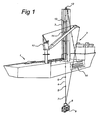
- Fig. 1 shows a vessel 1 comprising a lifting device 2 according to the present invention.
- the lifting device 2 comprises a vertical frame 3 carrying a cable 4 having at spaced-depart locations support members in the form of broadened parts 5, 6, 7.
- a connector 8 is provided attached to a load 9, which is being lowered via the cable 4.
- the cable 4 is stored in a looped configuration in a storage compartment or hawse-hole 10, substantially without being tensioned. From the storage compartment 10, the cable 4 is guided via a sheave 12 to a first lifting structure 13 and a second lifting structure 14.
- the fist lifting structure can travel up and down along the vertical frame 3 and can releasably engage with the broadened parts 5, 6, 7 on the cable 4.
- Stationary lifting structure 14 can also engage and be disengaged with the broadened parts 5, 6, 7.
- the load 9 is lowered.
- the lower lifting structure 14 is engaged with one of the broadened parts of the cable 4, whereas the lifting structure 13 disengages from the cable and is returned to its upper position.
- the load 9 can be successively lowered until it reaches the seabed, which may be at the depth of over 1500 m, such as at 3000 m or more.
- the load 9 is prior to being lowered from lifting device 2, placed overboard by a crane 17 which is thereafter disengaged such that the load be lowered from cable 4.
- the cable 4 may also be stored in the compartment 10 in a coiled from, for instance around a conical raised bottom part of compartment 10, or be stored on a drum or, again, alternatively as separate line sections.
- FIG. 2 show a detailed view of upper and lower lifting structures 13, 14.
- the upper lifting structure 13 comprises two parallel cylinders 20, 20', which are powered by hydraulic pump 22.
- Each cylinder comprises a sleeve 23, 23' and a rod 24, 24' moveably received within the sleeve 23, 23'.
- a pulley 25, 25' is connected. Both pulleys are interconnected via a frame 26.
- a moveable clamp 27, 27' is slidably connected along each rod 24, 24' and along each sleeve 23, 23'.
- the clamps 27, 27' are connected to the end part of a cable having a first cable section 28, 28' extending from the pulley 25, 25' to the respective clamp 27, 27' and a second cable section 29, 29' extending along the rod 24, 24' and sleeve 23, 23' to a fixed position 31, 31'.
- the lower lifting structure 14 is clampingly engaged via clamps 15, 15' with an end part of the cable 4.
- a cable section 32 is connected to the end part of cable 4 and is with its upper part engaged with clamps 27, 27' of upper lifting structure 13, such as shown in Fig. 3 . Thereafter, the clamps 15, 15' of the lower lifting structure 14 are opened, such as shown in Fig.
- the lifting structures 13, 14 are formed as an integral unit in a frame, which is suspended from the crane 17. In this way, heavy loads can be handled at large water depths from vessels having a standard crane by the lifting device of the present invention.
- Fig. 5 shows an embodiment of the lifting device 2 of the present invention in which the lifting device forms an abandonment and recovery system for retrieving a pipe system on a J-laying vessel 1.
- the lifting structures 13, 14 are also employed during pipe laying of the subsea pipeline.
- the pipeline may upon abandonment be connected to cable 4 having the spaced apart support members 5, 6, 7 stored in compartment 10 of the vessel.
- the abandoned pipeline which may have a weight of 300 T - 600 T may be lifted to the surface by cable 4 by alternate operation of lifting structures 13, 14.
- the support members 5, 6, 7 comprise collars having the same geometry as the collars employed on the interconnected pipe sections of the subsea pipeline, which may be a drill pipe.
- the cable 4 runs from the hawse-hole 10 in the hull of the vessel along the top of the J-laying frame 3 via a sheave structure 35 at the top of J-lay tower 3. There is no operational tension in the cable 4 between the sheave 35 and the hawse-hole 10.
- the sheave 35 is located at the centerline of the frame 3.
- the sheave 3 is located out of the center of the tower 3. The sheaves are wide enough to allow passage of the broadened collars 37 on the cable 4.
- Fig. 7-10 show different embodiments of a lifting device in which for similar elements like reference numerals have been used as in Fig. 1-6 .
- the vessel 1 in Fig. 7 has a schematically indicated lifting device 2 with a stationary lower lifting structure 14 and upper lifting structure 13 in the form of a transverse arm moveable along vertical frame 3.
- the cable 4 comprises separate segments, having at their upper end a broadened support member 5, 6, 7, such as a collar, to be engaged by clamps on arms 13, 14, and at their lower end a connector 36, 37, 38 engageable with the upper end of the adjacent cable section.
- Each cable section 34 may have a length of for instance 12 m and can be comprised of a synthetic material having substantially neutral buoyancy in water. Cable sections 34' with support members 5'-7' and connectors 36'-38' may be stored on the deck of the vessel 1.
- Fig. 8 shows an embodiment in which the cable 4 is a continuous cable stored on a drum 40. No substantial tension is present on the cable at the position of the drum 40. Separate support members 41 are connected to the cable each time upon stepwise lowering or raising of the load 9.
- the upstream lifting structure 13 is displaceable in a horizontal direction along the deck of the vessel 1.
- the cable 4 is a continuous cable guided along a sheave 42.
- Separate support members 41 are connectable to the cable 4 and spaced apart intervalls.
- Fig. 10 corresponds to the embodiment of Fig. 9 , but the cable 4 in this case is formed by cable sections 34, 34' having on one end part a support member 5' and on another end part a connector 36'.
- the upstream lifting structure 13 is displaceable in a horizontal direction along the deck of the vessel 1.
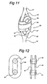
- Fig. 11 shows an embodiment of a support member 50 interconnecting two cable sections 51, 52 which are at their end parts provided with loops 53, 54.
- the cable sections 51, 52 may be formed of polyester or a cable material available under the trade name: Dyneema, as available from DSM, with a diameter of for instance 160 mm. Cable sections 51, 52 may also be formed of for instance Aramid fiber in a laid, plaited, braided or parallel subrope and sheath construction.
- the loops 53, 54 can be formed by standard splicing.
- the support member 50 comprises a collar 56 for engaging with the clamps on the upper and lower lifting structures 13, 14.
- Shackle plates 57, 57' are included through which connecting pins 58, 59 are inserted, connecting the parallel shackle plates 57, 57'.
- the diameter of the connecting pins 58 may for instance be 210 mm, whereas the distance between the center points of connecting pins 58, 59 may be about 330 mm.
- a flat shackle connection is shown wherein connector pins 60, 61 connect parallel shackle plates 59, 62.
- the shackle connector in Fig. 12 engages directly with the clamping construction of lifting structures 13, 14.
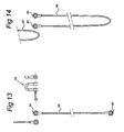
- Fig. 13 shows cable sections 63 having at each end a socket or splice 64, 65.
- the sockets of adjacent cable sections can be interconnected to a cable string connector 5 such as shackle 65.
- the cable sections 63 are looped such that the loop at the lower part of cable section 63 can be engaged with both collars 64, 65 of lower cable section 63 via shackle 65. In this case, a double cable strength is obtained.
- FIG 15 and 16 show a support member 70 in which a core 71 is used having spaced apart ribs 72, 73 along which strands 74 of cable 25 are guided.
- An outer sleeve 76 is placed around the core 71 having projections 78, 79 which engage in the space between the ribs 4 clamping the housing and core 71 in place by frictional engagement with strengths 74.
- a collar 80 is provided on the outer housing for engagement with lifting structures 13, 14.
- FIG. 17 shows a vessel 80 having a crane 81, carrying a lifting assembly 82 according to the present invention.
- the lifting assembly 82 comprises a frame 84 having a connector (eye) 83 attached to the cable 85 of the crane 81.
- the frame 84 carries lifting structures 13, 14 including pulleys 25, 25', cylinders 20, 20' and the clamps 15, 15', 27, 27', such as shown in Fig 2-4 .
- the crane 81 may use two cables, one attached to eye 83 and one attached to the movable lifting structure 13 for operating the movable lifting structure by the cable of the crane 81. In this way a standard crane can be made suitable for lifting and lowering heavy loads at large water depths, using the frame 84 and lifting cable 4 according to the present invention.
Landscapes
- Engineering & Computer Science (AREA)
- Mechanical Engineering (AREA)
- General Engineering & Computer Science (AREA)
- Ocean & Marine Engineering (AREA)
- Mining & Mineral Resources (AREA)
- Combustion & Propulsion (AREA)
- Life Sciences & Earth Sciences (AREA)
- Chemical & Material Sciences (AREA)
- Geology (AREA)
- General Life Sciences & Earth Sciences (AREA)
- Fluid Mechanics (AREA)
- Geochemistry & Mineralogy (AREA)
- Environmental & Geological Engineering (AREA)
- Physics & Mathematics (AREA)
- Architecture (AREA)
- Civil Engineering (AREA)
- Structural Engineering (AREA)
- Laying Of Electric Cables Or Lines Outside (AREA)
- Bridges Or Land Bridges (AREA)
- Revetment (AREA)
Abstract
Description
- The invention relates to a floating lifting device comprising an elongate member with a number of support members at spaced-apart locations along said elongate member, a first and a second lifting structure, each structure having a releasable engagement member for engaging with the support members on the elongate member and for carrying the elongate member by the respective lifting structure, at least one lifting structure being movable in the length direction of the elongate member between an upstream and a downstream position, the elongate member being lowered or raised by repeating steps a-d:
- a. moving the first lifting structure upstream or downstream, while the engagement member of the first lifting structure is closed and the engagement member of the second lifting structure is opened, such that the elongate member is suspended from the first lifting structure,
- b. closing the engagement member of the second lifting structure, and opening the engagement member of the first lifting structure, such that the elongate member is supported from the second lifting structure,
- c. moving the first lifting structure back towards or away from the second lifting structure, and
- d. closing the engagement member of the first lifting structure and opening the engagement member of the second lifting structure.
- Such a floating lifting device in the form of a J-lay pipe-laying vessel is known from
European patent application EP-A-0.657.670 . In this patent application a subsea pipeline is lowered to the seabed along a vertical tower, comprising a travel block movable along said tower. The pipeline comprises along its length collars, which can be engaged by the movable travel block, which can be opened and closed and can lower the pipes to a position in which they rest with a collar on a pedestal, whereafter the travel block can be disengaged and return. A new pipe section is added to the pipeline and the pipeline is again lowered via the travel block towards the seabed. - Other designs of lifting devices are known from documents
GB-A-2 302 076 US-A-3,602,413 ,US-A-5,199,659 andUS-A-4,447,013 , respectively. - It is an object of the present invention to provide a lifting structure with which a variety of heavy objects can be raised from and lowered towards the seabed.
- It is a further object of the present invention to provide a floating lifting device for lifting heavy subsea equipment and structures, such as templates, wellheads and the like in large water depths, i.e. water depths over 1000 m.
- It is a further object of the present invention to provide a relatively simple lifting device which may reduce costs of for instance an abandonment and recovery system of a pipe-lay vessel and which consumes relatively little space.
- Thereto, the floating lifting device of the present invention is characterised in that the elongate member is a cable having at an end part a connector for releasably attaching objects to the end of said line, the lifting device comprising a line storage member from which during carrying out steps a-d, the line is supplied without being tensioned.
- With the lifting device of the present invention it is possible to use a flexible line or cable for lifting and lowering heavy objects, which line can be stored without significant tension on the vessel. In contrast, lifting winches using steel cable are known, which cable is stored on a drum and runs along a traction winch in several loops for reducing the tension on the cable at the drum. The tensioned cable on the drum causes a frictional corrosion and consequent damage of the cable.
- Furthermore, steel cables are less effective at water depths larger than 1500 m as the weight of the cable becomes prohibitive and the amount of space consumed by the stored cable on the drum is particularly large. The use of synthetic cables, stored on a known winch, is unfavorable in view of slippage and consequent frictional damage to the cables, such as the possibility of the outer cable jacket being burned or melting.
- With the present invention, the non-used part of the cable can be stored in a non-tensioned manner on the vessel. This means that a synthetic cable can be used, stored on a drum or stored in a looped configuration in a box-shaped compartment (hawse-hole) of the vessel. Alternatively, separate cable sections may be stored on the vessel in a straight-line configuration, the cable sections being interconnected at the moment of use. Hereby, a very flexible system, which can accommodate different water depths, is obtained. If sufficient cable strength is not available for lifting or lowering a specific object, even looped cable sections can be employed in the method of the present invention to obtain sufficient cable strength. The present invention allows the use of a very long synthetic cable of 1000 m or longer, preferably 1500 m or longer, which might be formed by interconnected synthetic cable segments. It is even possible to combine a standard steel cable in strings with synthetic cable strings.
- The present lifting device may be employed as an abandonment and recovery system in a J-laying vessel, which is used to abandon the pipeline to the seabed and to recover it afterwards for instance in case of severe weather conditions. Regularly employed abandonment and recovery systems use a double capstan winch for reconnecting the pipeline to the J-lay tower. By use of the cable of the present invention, a simple abandonment and recovery construction is obtained which may employ the lifting force of the J-lay tower. Hereby, it is no longer necessary to employ an additional winch as a abandonment and recovery system, such that large cost saving is obtained and extra space on the vessel is made available. A double capstan winch suitable for a water depth of 3000 m including the required steel cable, is very heavy and bulky. Such a conventional abandonment and recovery system would double the weight of a conventional J-lay system, which can be prevented by use of the lifting device of the present invention.
- Alternatively, the lifting device of the present invention is not employed in combination with pipe laying, but for installation of other heavy subsea equipment and structures such as templates, wellheads etc. at large water depths. The lifting structures may form an assembly, which is suspended from a crane.
- In one embodiment, the lifting cable is stored in a looped configuration. In case the cable is a synthetic cable, the cable can be placed in a conventional hawser compartment in a looped configuration. The synthetic cable has substantially neutral buoyancy, such that the full capacity of the lifting device can be used for raising and lowering of the load.
- In an alternative embodiment, separate cable segments are employed, which are added successively as the weight is lowered or are removed when the weight is raised. The cable segments may be stored on deck or below deck in a hawser compartment or other suitable tension less storing configurations. The cable sections may be interconnected by members such as shackles, which at the same time form the support members by which the object is lifted.
- In one embodiment, each cable section is provided at its end with an eye, the eyes of adjacent cables being attached by a suitable connector, such as a shackle. The interconnected broad end sections can at the same time form the support members for lifting and lowering the cable. For protecting the interconnections from being damaged, a collar might be placed around the interconnected eyes of the cable.
- In a further embodiment, the support member in the cable may comprise an inner core, having along its length a number of circumferential ribs, fiber strands being placed on the core and over the ribs. An outer sleeve encloses the core, while an inner surface of the sleeve is provided with projections that are complementary to the ribs on the core and are received between the ribs of the core. The support member is maintained in its axial position by friction, which is determined by the number and depth of the circumferential ribs of the core. In this embodiment, the position of the support member along the line and number of support members can be easily adjusted upon manufacturing of the lifting line.
- A suitable lifting device comprises a first lifting structure with two parallel rods, each rod telescopically received in a sleeve to be displaceable in the length direction of the line, a drive member connected to the rods for displacing the rods in the length direction, a pulley being connected at the end of each rod, a movable clamp being placed on each rod, the opposed clamps of the rods forming the first lifting structure, the clamps being connected to lifting cable running long the rod, around the pulley and downward along the rods to a point of fixation.
- By this lifting device, a relatively large stroke for lowering or raising can be obtained with a relatively compact construction with a first displacement given by telescopic movement of the parallel rods and a second displacement step being possible by lowering the clamps along the sleeves.
- Some embodiments of a lifting device according to the present invention will be explained in detail with reference to the accompanying drawings. In the drawings:
-
Fig. 1 shows a perspective view of a floating lifting device according to the present invention; -
Fig. 2-4 show different stages of lowering a heavy weight with the lifting device according to the present invention; -
Fig. 5 shows a detail of a frame comprising a lifting device of the present invention; -
Fig. 6 shows a perspective view of a sheave guiding a lifting cable according to the present invention; -
Fig. 7-10 show alternative embodiments of lifting devices of the present invention; -
Fig. 11 shows a detail of a connecting collar for connecting two line sections; -
Fig. 12 shows a plan frontal view and side view of a shackle for interconnecting two line sections according to the present invention; -
Fig. 13 and 14 show alternative embodiments of interconnecting two synthetic line sections; -
Fig. 15 and 16 show an embodiment of a support member according to the present invention; and -
Fig. 17 shows a lifting assembly for deep water suspended from a crane. -
Fig. 1 shows avessel 1 comprising alifting device 2 according to the present invention. Thelifting device 2 comprises avertical frame 3 carrying acable 4 having at spaced-depart locations support members in the form of broadenedparts cable 6, aconnector 8 is provided attached to a load 9, which is being lowered via thecable 4. Thecable 4 is stored in a looped configuration in a storage compartment or hawse-hole 10, substantially without being tensioned. From thestorage compartment 10, thecable 4 is guided via asheave 12 to afirst lifting structure 13 and asecond lifting structure 14. The fist lifting structure can travel up and down along thevertical frame 3 and can releasably engage with the broadenedparts cable 4.Stationary lifting structure 14 can also engage and be disengaged with the broadenedparts upper lifting structure 14 and lowering the cable suspended from liftingstructure 13, the load 9 is lowered. After lowering the broadened part clamped in theupper lifting structure 13 by a certain amount, thelower lifting structure 14 is engaged with one of the broadened parts of thecable 4, whereas the liftingstructure 13 disengages from the cable and is returned to its upper position. In this way, the load 9 can be successively lowered until it reaches the seabed, which may be at the depth of over 1500 m, such as at 3000 m or more. The load 9 is prior to being lowered from liftingdevice 2, placed overboard by acrane 17 which is thereafter disengaged such that the load be lowered fromcable 4. - As an alternative to the looped configuration, the
cable 4 may also be stored in thecompartment 10 in a coiled from, for instance around a conical raised bottom part ofcompartment 10, or be stored on a drum or, again, alternatively as separate line sections. -
Fig. 2 show a detailed view of upper andlower lifting structures upper lifting structure 13 comprises twoparallel cylinders 20, 20', which are powered byhydraulic pump 22. Each cylinder comprises asleeve 23, 23' and arod 24, 24' moveably received within thesleeve 23, 23'. At the end of eachrod 24, 24' apulley 25, 25' is connected. Both pulleys are interconnected via aframe 26. Amoveable clamp 27, 27' is slidably connected along eachrod 24, 24' and along eachsleeve 23, 23'. The clamps 27, 27' are connected to the end part of a cable having afirst cable section 28, 28' extending from thepulley 25, 25' to therespective clamp 27, 27' and asecond cable section 29, 29' extending along therod 24, 24' andsleeve 23, 23' to a fixedposition 31, 31'. As shown inFig. 2 , thelower lifting structure 14 is clampingly engaged viaclamps 15, 15' with an end part of thecable 4. Acable section 32 is connected to the end part ofcable 4 and is with its upper part engaged withclamps 27, 27' ofupper lifting structure 13, such as shown inFig. 3 . Thereafter, theclamps 15, 15' of thelower lifting structure 14 are opened, such as shown inFig. 4 , whileupper clamps 27, 27' remain engaged with the broadened part on theupper cable section 32. Under control of thehydraulic pump 22, therods 24, 24' are under the weight of thecable 4 and load 9, pulled intosleeves 23, 23' such that theclamps 27, 27' descend along thesleeves 23, 23'. In the lowered position, theclamps 15, 15' engages with theend part 33 ofcable section 32. Hereby, the whole cable weight and the weight of the load 9 is again supported from thelower lifting structure 14. The clamps 27, 27' are then disengaged and thepulleys 25, 25' are returned to their upper position as shown inFig. 4 . In an advantageous embodiment, the liftingstructures crane 17. In this way, heavy loads can be handled at large water depths from vessels having a standard crane by the lifting device of the present invention. -
Fig. 5 shows an embodiment of thelifting device 2 of the present invention in which the lifting device forms an abandonment and recovery system for retrieving a pipe system on a J-layingvessel 1. In this case, the liftingstructures cable 4 having the spaced apartsupport members compartment 10 of the vessel. The abandoned pipeline, which may have a weight of 300 T - 600 T may be lifted to the surface bycable 4 by alternate operation of liftingstructures support members - The
cable 4 runs from the hawse-hole 10 in the hull of the vessel along the top of the J-layingframe 3 via asheave structure 35 at the top of J-lay tower 3. There is no operational tension in thecable 4 between thesheave 35 and the hawse-hole 10. Thesheave 35 is located at the centerline of theframe 3. To avoid interference between thecable 4 andtower adjuster 36, thesheave 3 is located out of the center of thetower 3. The sheaves are wide enough to allow passage of the broadenedcollars 37 on thecable 4. -
Fig. 7-10 show different embodiments of a lifting device in which for similar elements like reference numerals have been used as inFig. 1-6 . Thevessel 1 inFig. 7 has a schematically indicated liftingdevice 2 with a stationarylower lifting structure 14 andupper lifting structure 13 in the form of a transverse arm moveable alongvertical frame 3. Thecable 4 comprises separate segments, having at their upper end a broadenedsupport member arms connector cable section 34 may have a length of for instance 12 m and can be comprised of a synthetic material having substantially neutral buoyancy in water. Cable sections 34' with support members 5'-7' and connectors 36'-38' may be stored on the deck of thevessel 1. -
Fig. 8 shows an embodiment in which thecable 4 is a continuous cable stored on adrum 40. No substantial tension is present on the cable at the position of thedrum 40.Separate support members 41 are connected to the cable each time upon stepwise lowering or raising of the load 9. - In the embodiment of
Fig. 9 , theupstream lifting structure 13 is displaceable in a horizontal direction along the deck of thevessel 1. Thecable 4 is a continuous cable guided along asheave 42.Separate support members 41 are connectable to thecable 4 and spaced apart intervalls. - The embodiment of
Fig. 10 corresponds to the embodiment ofFig. 9 , but thecable 4 in this case is formed bycable sections 34, 34' having on one end part a support member 5' and on another end part a connector 36'. Again, theupstream lifting structure 13 is displaceable in a horizontal direction along the deck of thevessel 1. -
Fig. 11 shows an embodiment of asupport member 50 interconnecting twocable sections loops cable sections Cable sections loops support member 50 comprises acollar 56 for engaging with the clamps on the upper andlower lifting structures Shackle plates 57, 57' are included through which connecting pins 58, 59 are inserted, connecting theparallel shackle plates 57, 57'. The diameter of the connectingpins 58 may for instance be 210 mm, whereas the distance between the center points of connectingpins - In the embodiment of
Fig. 12 , a flat shackle connection is shown wherein connector pins 60, 61 connectparallel shackle plates Fig. 12 engages directly with the clamping construction of liftingstructures -
Fig. 13 showscable sections 63 having at each end a socket orsplice cable string connector 5 such asshackle 65. InFig. 14 , thecable sections 63 are looped such that the loop at the lower part ofcable section 63 can be engaged with bothcollars lower cable section 63 viashackle 65. In this case, a double cable strength is obtained. - Finally,
Fig 15 and 16 show asupport member 70 in which acore 71 is used having spaced apartribs strands 74 ofcable 25 are guided. Anouter sleeve 76 is placed around thecore 71 havingprojections ribs 4 clamping the housing andcore 71 in place by frictional engagement withstrengths 74. Acollar 80 is provided on the outer housing for engagement with liftingstructures - By the use of synthetic cables, objects can be lifted from large water depths without the cable weight, which may have substantially neutral buoyancy, adding to the load. The cable length and cable strength can be easily adjusted to the prevailing water depth and weight of the load.
- Finally,
Fig. 17 shows avessel 80 having acrane 81, carrying a liftingassembly 82 according to the present invention. The liftingassembly 82 comprises aframe 84 having a connector (eye) 83 attached to thecable 85 of thecrane 81. Theframe 84carries lifting structures pulleys 25, 25',cylinders 20, 20' and theclamps Fig 2-4 . - The
crane 81 may use two cables, one attached to eye 83 and one attached to themovable lifting structure 13 for operating the movable lifting structure by the cable of thecrane 81. In this way a standard crane can be made suitable for lifting and lowering heavy loads at large water depths, using theframe 84 and liftingcable 4 according to the present invention.
Claims (15)
- Floating lifting device (2) comprising an elongate member (4) with a number of support members (5, 6, 7) at spaced-apart locations along said elongate member (4), a first (13) and a second (14) lifting structure, each structure having a releasable engagement member (15, 15', 27, 27') for engaging with the support members (5, 6, 7) on the elongate member (4) and for carrying the elongate member (4) by the respective lifting structure, at least one lifting structure (13) being movable in the length direction of the elongate member between an upstream and a downstream position, the elongate member (4) being lowered or raised by repeating steps a-d:a. moving the first lifting structure (13) upstream or downstream, while the engagement member (27, 27') of the first structure (13) is closed and the engagement member (15, 15') of the second lifting structure (14) is opened, such that the elongate member (4) is suspended from the first lifting structure (13),b. closing the engagement member (15, 15') of the second lifting structure (14), and opening the engagement member (27, 27') of the first lifting structure (13), such that the elongate member (4) is supported from the second lifting structure (14),c. moving the first lifting structure (13) back towards or away from the second lifting structure (14), andd. closing the engagement member (27, 27') of the first lifting structure and opening the engagement member (15, 15') of the second lifting structure (14), characterised in that,the elongate member (4) is a cable having at an end part a connector (8) for releasably attaching objects to the end part of said cable, the lifting device comprising a cable storage member (10, 40) from which during carrying out steps a-d, the cable (4) is supplied substantially without being tensioned.
- Lifting device (2) according to claim 1, wherein the cable storage member (10) comprises a compartment in which the cable is stored in a looped configuration.
- Lifting device (2) according to claim 1, wherein separate cable segments (34, 34') are stored in the cable storage member, for being added to the cable prior to carrying out steps a-d.
- Lifting device (2) according to any of the preceding claims, the cable being formed of a wire rope.
- Lifting device (2) according to claim 4, the cable being formed of a substantially neutral buoyant synthetic material.
- Lifting device (2) according to claim 4, the cable comprising interconnectable cable sections (34', 63, 63').
- Lifting device (2) according to claim 5, the support members (5,6,7) being formed by interconnecting members (50, 64, 65) of two interconnected cable sections (34, 63, 63').
- Lifting device (2) according to claim 6, an interconnecting member comprising an eye (64, 65) at each end of a cable section (63, 63'), the eyes of two adjacent cable sections being interconnected by a connector (65), such as a shackle.
- Lifting device (2) according to claim 7, a collar (56) being positioned around the interconnected eyes (53, 54).
- Lifting device (2) according to claim 4, the cable comprising a number of strands (74), the support members (70) comprising an inner core (71) having along its length a number of circumferential ribs (72, 73), the strands being placed on the the core and over the ribs, and an outer sleeve (76) enclosing the core, the sleeve having on an inner surface a number of projections (78, 79) that are complementary to the ribs on the core, the projections being received between the ribs of the core.
- Lifting device (2) according to any of the preceding claims, the first lifting structure (13) comprising two parallel rods (29, 29'), each rod telescopically received in a sleeve (23, 23') to be displaceable in the length direction of the line, a drive member (22) connected to the rods for displacing the rods in the length direction, a pulley (25, 25') being connected at the end of each rod (29, 29'), a movable clamp (27, 27') being placed on each rod, the opposed clamps (27, 27') of the rods forming part of the first lifting structure (13), the clamps being connected to a lifting cable (28, 28', 29, 29') running from each respective clamp (27, 27') along the rods (29, 29'), around the pulleys (25, 25') and downward along the rods to a point of fixation (31, 31').
- Lifting device (2) according to claim 10, the clamps (27, 27') being slidable along the rods (29, 29') and along the sleeves (23, 23').
- Lifting device (2) according to any of the preceding claims, the first and second support members (13, 14) forming an integral unit attached to a crane.
- Lifting assembly (82), comprising a floating lifting device (2) according to any of the preceding claims and further comprising attachment means (83) for suspending the lifting assembly (82) for a cable of a crane.
- Lifting assembly (82) according to claim 14, comprising a crane, said movable lifting structure (13) being operated by a cable of the crane connected to said movable lifting structure (13), a second cable of the crane being connected to the attachment means (83).
Priority Applications (1)
| Application Number | Priority Date | Filing Date | Title |
|---|---|---|---|
| EP03705483A EP1467944B2 (en) | 2002-01-25 | 2003-01-27 | Floating lifting device |
Applications Claiming Priority (4)
| Application Number | Priority Date | Filing Date | Title |
|---|---|---|---|
| EP02075311A EP1331191A1 (en) | 2002-01-25 | 2002-01-25 | Floating lifting device |
| EP02075311 | 2002-01-25 | ||
| PCT/NL2003/000054 WO2003062112A2 (en) | 2002-01-25 | 2003-01-27 | Floating lifting device |
| EP03705483A EP1467944B2 (en) | 2002-01-25 | 2003-01-27 | Floating lifting device |
Publications (3)
| Publication Number | Publication Date |
|---|---|
| EP1467944A2 EP1467944A2 (en) | 2004-10-20 |
| EP1467944B1 EP1467944B1 (en) | 2006-11-02 |
| EP1467944B2 true EP1467944B2 (en) | 2010-07-14 |
Family
ID=8185566
Family Applications (2)
| Application Number | Title | Priority Date | Filing Date |
|---|---|---|---|
| EP02075311A Withdrawn EP1331191A1 (en) | 2002-01-25 | 2002-01-25 | Floating lifting device |
| EP03705483A Expired - Lifetime EP1467944B2 (en) | 2002-01-25 | 2003-01-27 | Floating lifting device |
Family Applications Before (1)
| Application Number | Title | Priority Date | Filing Date |
|---|---|---|---|
| EP02075311A Withdrawn EP1331191A1 (en) | 2002-01-25 | 2002-01-25 | Floating lifting device |
Country Status (4)
| Country | Link |
|---|---|
| US (1) | US7182212B2 (en) |
| EP (2) | EP1331191A1 (en) |
| NO (1) | NO331908B1 (en) |
| WO (1) | WO2003062112A2 (en) |
Families Citing this family (17)
| Publication number | Priority date | Publication date | Assignee | Title |
|---|---|---|---|---|
| US7395899B2 (en) | 2003-01-27 | 2008-07-08 | Exterior Elevator, Llc | Method and apparatus for reaching from outside an upper level of a tall structure |
| US7537087B2 (en) * | 2004-01-23 | 2009-05-26 | Exterior Elevator, Llc | Method and apparatus for reaching from outside an upper level of a tall structure |
| EP1725800B1 (en) | 2004-03-10 | 2016-08-17 | SBM Schiedam B.V. | Light-weight versatile j-lay system |
| DE102005008087B4 (en) * | 2004-11-15 | 2023-10-05 | Liebherr-Werk Biberach Gmbh | crane |
| US8783478B2 (en) * | 2007-10-11 | 2014-07-22 | Itrec B.V. | Hoisting crane and offshore vessel |
| NL2001758C2 (en) * | 2008-07-04 | 2010-01-05 | Zwijnenberg Evert Hendrik Will | Auxiliary device for placement between a first object providing a pulling or pushing force and a second object on which the pulling or pushing force is exerted. |
| GB0819400D0 (en) * | 2008-10-22 | 2008-11-26 | Subsea 7 | Offshore lifting operations |
| DE202009014031U1 (en) * | 2009-10-16 | 2009-12-24 | Manitowoc Crane Group France Sas | Synthetic rope as a carrier for cranes and other hoists |
| GB2488767B (en) | 2011-03-07 | 2013-06-05 | Technip France | Abandonment and recovery system |
| NL2009028C2 (en) * | 2012-06-18 | 2013-12-23 | Itrec Bv | Off-shore installation vessel, method of operating an off-shore installation vessel. |
| US8690202B2 (en) * | 2012-08-09 | 2014-04-08 | Mark Lankford | Control mechanism |
| US9321616B2 (en) | 2013-03-14 | 2016-04-26 | Marvin M. May | Lifting systems |
| US20150191222A1 (en) * | 2014-01-07 | 2015-07-09 | Reel Power Licensing Corp. | Method of Motion Compensation with Synthetic Rope |
| BR112016025021A2 (en) * | 2014-04-29 | 2017-08-15 | Itrec Bv | ? pipe installation vessel, and, marine spool disposal method? |
| US9346656B2 (en) | 2014-07-01 | 2016-05-24 | Marvin M. May | Stabilization and control of a crane load |
| CN105752861B (en) * | 2014-12-19 | 2017-12-12 | 中石化胜利石油工程有限公司钻井工艺研究院 | Using buoyant mass and hang the method for leading dual-purpose rope installation deep-sea underwater heavy facility |
| NL2017674B1 (en) * | 2016-10-25 | 2018-05-04 | Itrec Bv | Rope handling system, vessel provided with such a rope handling system and method of handling synthetic rope |
Citations (1)
| Publication number | Priority date | Publication date | Assignee | Title |
|---|---|---|---|---|
| WO1999035429A1 (en) † | 1998-01-09 | 1999-07-15 | Coflexip | Device and method for installing conduits at very great depths |
Family Cites Families (21)
| Publication number | Priority date | Publication date | Assignee | Title |
|---|---|---|---|---|
| US2924328A (en) * | 1960-02-09 | D lidderdale | ||
| NL16389C (en) * | 1922-02-03 | |||
| US2986889A (en) * | 1958-06-25 | 1961-06-06 | California Research Corp | Anchoring systems |
| US3499629A (en) * | 1968-03-19 | 1970-03-10 | Ocean Science & Eng | Constant tension chain jack assembly |
| FR1602113A (en) * | 1968-09-10 | 1970-10-12 | ||
| US3724567A (en) * | 1970-11-30 | 1973-04-03 | E Smitherman | Apparatus for handling column of drill pipe or tubing during drilling or workover operations |
| US4191300A (en) * | 1975-02-18 | 1980-03-04 | Rene Beghi | Hoisting device for high-power crane |
| FR2346588A1 (en) * | 1975-10-20 | 1977-10-28 | Pradon Jacques | PLIERS OF TIGHTENING |
| SE450184B (en) * | 1980-04-23 | 1987-06-09 | Bror Sandered | WHEN RACING, WINDING, TOWING ETC OF A RULE CABLE OR OTHER SIMILAR LONG-TERM PUBLIC FORMAL AND DEVICE FOR ITS IMPLEMENTATION |
| US4446807A (en) * | 1981-06-10 | 1984-05-08 | American Hoist & Derrick Company | Mooring apparatus for floating vessels |
| US4734961A (en) * | 1982-05-24 | 1988-04-05 | Guthmann Stephen F | Sliding bolt pressing surfaces type rope widening apparatus |
| US5199659A (en) * | 1991-04-22 | 1993-04-06 | Shell Offshore Inc. | Seismic cable retrieval apparatus and method |
| US5421675A (en) * | 1993-11-18 | 1995-06-06 | Mcdermott International, Inc. | Apparatus for near vertical laying of pipeline |
| FR2717148B1 (en) * | 1994-03-10 | 1996-07-12 | Ifremer | Method of recovering a cargo on board a wreck. |
| NL194836C (en) * | 1995-03-10 | 2003-04-03 | Allseas Group Sa | Device for laying a pipeline on a submerged soil. |
| GB2302076B (en) * | 1995-06-09 | 1999-03-31 | Asep Bv | Conveying apparatus |
| US6044786A (en) * | 1996-08-23 | 2000-04-04 | Western Atlas International, Inc. | Seismic cable retrieval system |
| US6070857A (en) * | 1996-11-12 | 2000-06-06 | Odim Holding A/S | Device for the storage and deployment of ocean bottom seismic cable |
| GB9930492D0 (en) | 1999-12-23 | 2000-02-16 | Saipem Spa | Improvements in and relating to laying of pipeline |
| US6378614B1 (en) * | 2000-06-02 | 2002-04-30 | Oil & Gas Rental Services, Inc. | Method of landing items at a well location |
| EP1406006B1 (en) | 2002-10-04 | 2005-06-29 | Robert Bosch Gmbh | Fuel injection valve |
-
2002
- 2002-01-25 EP EP02075311A patent/EP1331191A1/en not_active Withdrawn
-
2003
- 2003-01-27 WO PCT/NL2003/000054 patent/WO2003062112A2/en active IP Right Grant
- 2003-01-27 EP EP03705483A patent/EP1467944B2/en not_active Expired - Lifetime
-
2004
- 2004-07-23 US US10/898,535 patent/US7182212B2/en not_active Expired - Lifetime
- 2004-08-24 NO NO20043534A patent/NO331908B1/en not_active IP Right Cessation
Patent Citations (1)
| Publication number | Priority date | Publication date | Assignee | Title |
|---|---|---|---|---|
| WO1999035429A1 (en) † | 1998-01-09 | 1999-07-15 | Coflexip | Device and method for installing conduits at very great depths |
Also Published As
| Publication number | Publication date |
|---|---|
| WO2003062112A3 (en) | 2004-08-05 |
| NO20043534L (en) | 2004-10-25 |
| US7182212B2 (en) | 2007-02-27 |
| WO2003062112A2 (en) | 2003-07-31 |
| NO331908B1 (en) | 2012-04-30 |
| EP1467944B1 (en) | 2006-11-02 |
| EP1331191A1 (en) | 2003-07-30 |
| US20050109724A1 (en) | 2005-05-26 |
| EP1467944A2 (en) | 2004-10-20 |
Similar Documents
| Publication | Publication Date | Title |
|---|---|---|
| EP1467944B2 (en) | Floating lifting device | |
| US7543799B2 (en) | Method and apparatus for deploying articles in deep waters | |
| EP1850043B1 (en) | Abandonment and recovery system and method, and cable connector | |
| DK2424775T3 (en) | A method and system for sharing a mooring line | |
| AU2011204506B2 (en) | Improvements relating to abandonment and recovery of pipelines | |
| EP2235413B1 (en) | System and method for installing a subsea pipeline | |
| EP2683973B1 (en) | Abandonment and recovery system | |
| WO2004085898A1 (en) | Apparatus and methods for laying of elongate articles from a vessel | |
| EP2480811B1 (en) | Method and hoisting assembly for abandoning and/or recovering an underwater pipeline by means of a laying vessel and laying vessel and laying vessel equipped with such hoisting assembly | |
| DK202270471A1 (en) | A fish farming plant and methods of operation | |
| KR20130098624A (en) | Floating support apparatus for pipeline, pipe laying vessel using the floating support apparatus, and submerged-pipeline installation method using the floating support apparatus | |
| BR112021002657A2 (en) | maneuvering loads in subsea operations | |
| US4687377A (en) | Method and apparatus for subsea flexible conduit installation | |
| WO2005078325A1 (en) | Device for protection of elongate element on a seabed and method for the installation of same | |
| AU2012241123B2 (en) | Abandonment and recovery system and method, and cable connector | |
| NL2006810C2 (en) | Recovery device for recovering a pipeline after the abandonment thereof on the seabed on an s-lay vessel. |
Legal Events
| Date | Code | Title | Description |
|---|---|---|---|
| PUAI | Public reference made under article 153(3) epc to a published international application that has entered the european phase |
Free format text: ORIGINAL CODE: 0009012 |
|
| 17P | Request for examination filed |
Effective date: 20040709 |
|
| AK | Designated contracting states |
Kind code of ref document: A2 Designated state(s): AT BE BG CH CY CZ DE DK EE ES FI FR GB GR HU IE IT LI LU MC NL PT SE SI SK TR |
|
| AX | Request for extension of the european patent |
Extension state: AL LT LV MK RO |
|
| GRAP | Despatch of communication of intention to grant a patent |
Free format text: ORIGINAL CODE: EPIDOSNIGR1 |
|
| REG | Reference to a national code |
Ref country code: DE Ref legal event code: 8566 |
|
| GRAS | Grant fee paid |
Free format text: ORIGINAL CODE: EPIDOSNIGR3 |
|
| GRAA | (expected) grant |
Free format text: ORIGINAL CODE: 0009210 |
|
| AK | Designated contracting states |
Kind code of ref document: B1 Designated state(s): FR GB NL |
|
| REG | Reference to a national code |
Ref country code: GB Ref legal event code: FG4D |
|
| ET | Fr: translation filed | ||
| PLBI | Opposition filed |
Free format text: ORIGINAL CODE: 0009260 |
|
| PLAX | Notice of opposition and request to file observation + time limit sent |
Free format text: ORIGINAL CODE: EPIDOSNOBS2 |
|
| 26 | Opposition filed |
Opponent name: TECHNIP FRANCE Effective date: 20070801 |
|
| NLR1 | Nl: opposition has been filed with the epo |
Opponent name: TECHNIP FRANCE |
|
| PLBB | Reply of patent proprietor to notice(s) of opposition received |
Free format text: ORIGINAL CODE: EPIDOSNOBS3 |
|
| APBM | Appeal reference recorded |
Free format text: ORIGINAL CODE: EPIDOSNREFNO |
|
| APBP | Date of receipt of notice of appeal recorded |
Free format text: ORIGINAL CODE: EPIDOSNNOA2O |
|
| APAH | Appeal reference modified |
Free format text: ORIGINAL CODE: EPIDOSCREFNO |
|
| APBU | Appeal procedure closed |
Free format text: ORIGINAL CODE: EPIDOSNNOA9O |
|
| PUAH | Patent maintained in amended form |
Free format text: ORIGINAL CODE: 0009272 |
|
| STAA | Information on the status of an ep patent application or granted ep patent |
Free format text: STATUS: PATENT MAINTAINED AS AMENDED |
|
| 27A | Patent maintained in amended form |
Effective date: 20100714 |
|
| AK | Designated contracting states |
Kind code of ref document: B2 Designated state(s): FR GB NL |
|
| REG | Reference to a national code |
Ref country code: NL Ref legal event code: T3 |
|
| REG | Reference to a national code |
Ref country code: NL Ref legal event code: TD Effective date: 20111024 |
|
| REG | Reference to a national code |
Ref country code: FR Ref legal event code: CD Owner name: SBM SCHIEDAM B.V., NL Effective date: 20120321 Ref country code: FR Ref legal event code: CA Effective date: 20120321 |
|
| REG | Reference to a national code |
Ref country code: FR Ref legal event code: PLFP Year of fee payment: 13 |
|
| REG | Reference to a national code |
Ref country code: FR Ref legal event code: PLFP Year of fee payment: 14 |
|
| REG | Reference to a national code |
Ref country code: FR Ref legal event code: PLFP Year of fee payment: 15 |
|
| REG | Reference to a national code |
Ref country code: NL Ref legal event code: PD Owner name: SINGLE BUOY MOORINGS INC.; CH Free format text: DETAILS ASSIGNMENT: CHANGE OF OWNER(S), ASSIGNMENT; FORMER OWNER NAME: SBM SCHIEDAM B.V. Effective date: 20171130 |
|
| REG | Reference to a national code |
Ref country code: FR Ref legal event code: PLFP Year of fee payment: 16 |
|
| REG | Reference to a national code |
Ref country code: GB Ref legal event code: 732E Free format text: REGISTERED BETWEEN 20180201 AND 20180207 |
|
| REG | Reference to a national code |
Ref country code: FR Ref legal event code: TP Owner name: SINGLE BUOY MOORINGS INC, CH Effective date: 20180330 |
|
| PGFP | Annual fee paid to national office [announced via postgrant information from national office to epo] |
Ref country code: GB Payment date: 20220118 Year of fee payment: 20 |
|
| PGFP | Annual fee paid to national office [announced via postgrant information from national office to epo] |
Ref country code: NL Payment date: 20220110 Year of fee payment: 20 Ref country code: FR Payment date: 20220126 Year of fee payment: 20 |
|
| REG | Reference to a national code |
Ref country code: NL Ref legal event code: MK Effective date: 20230126 |
|
| REG | Reference to a national code |
Ref country code: GB Ref legal event code: PE20 Expiry date: 20230126 |
|
| PG25 | Lapsed in a contracting state [announced via postgrant information from national office to epo] |
Ref country code: GB Free format text: LAPSE BECAUSE OF EXPIRATION OF PROTECTION Effective date: 20230126 |