EP1467309A1 - Agencement pour le blocage d'un support de données dans un dispositif d'échange de données - Google Patents
Agencement pour le blocage d'un support de données dans un dispositif d'échange de données Download PDFInfo
- Publication number
- EP1467309A1 EP1467309A1 EP04101338A EP04101338A EP1467309A1 EP 1467309 A1 EP1467309 A1 EP 1467309A1 EP 04101338 A EP04101338 A EP 04101338A EP 04101338 A EP04101338 A EP 04101338A EP 1467309 A1 EP1467309 A1 EP 1467309A1
- Authority
- EP
- European Patent Office
- Prior art keywords
- locking
- housing
- arrangement
- data carrier
- blocking
- Prior art date
- Legal status (The legal status is an assumption and is not a legal conclusion. Google has not performed a legal analysis and makes no representation as to the accuracy of the status listed.)
- Granted
Links
Images


Classifications
-
- G—PHYSICS
- G06—COMPUTING OR CALCULATING; COUNTING
- G06K—GRAPHICAL DATA READING; PRESENTATION OF DATA; RECORD CARRIERS; HANDLING RECORD CARRIERS
- G06K13/00—Conveying record carriers from one station to another, e.g. from stack to punching mechanism
- G06K13/02—Conveying record carriers from one station to another, e.g. from stack to punching mechanism the record carrier having longitudinal dimension comparable with transverse dimension, e.g. punched card
- G06K13/08—Feeding or discharging cards
- G06K13/085—Feeding or discharging cards using an arrangement for locking the inserted card
-
- G—PHYSICS
- G06—COMPUTING OR CALCULATING; COUNTING
- G06K—GRAPHICAL DATA READING; PRESENTATION OF DATA; RECORD CARRIERS; HANDLING RECORD CARRIERS
- G06K13/00—Conveying record carriers from one station to another, e.g. from stack to punching mechanism
- G06K13/02—Conveying record carriers from one station to another, e.g. from stack to punching mechanism the record carrier having longitudinal dimension comparable with transverse dimension, e.g. punched card
- G06K13/08—Feeding or discharging cards
Definitions
- the present invention relates to an arrangement for data exchange between a rigid or semi-rigid data carrier and a device data exchange, in particular for reading data contained in the support.
- the invention relates more particularly to such an arrangement intended for equip a motor vehicle and in which the data carrier, for example in the form of a generally rectangular card or badge, carries vehicle user identification data that authorize it when inserting the support into the reading device, to use the vehicle in particular by allowing it to start the engine of the vehicle.
- the data carrier for example in the form of a generally rectangular card or badge, carries vehicle user identification data that authorize it when inserting the support into the reading device, to use the vehicle in particular by allowing it to start the engine of the vehicle.
- the data medium comprises for example a circuit integrated, or chip, which is connected to means for reading the device by electrical contacts and / or by a data exchange antenna.
- the badge or card When the badge or card is inserted into the device, it is manually inserted into a housing of the housing in which the support of data occupies a determined active position, and the device which receives the card or badge includes means for retaining longitudinally this data carrier in the active position in the housing so that data exchange is ensured in good conditions.
- these retaining means are constituted by simple brakes, that is to say that they are legs elastically deformable which cooperate by friction with edges side and / or with the large sides of the card.
- the device comprises a motorized drawer in which the card is inserted manually and which is then electrically controlled in movement between its rest position into which the card is inserted and an active reading position in which the drawer brings the card next to reading means.
- Such a design is complex and cumbersome and hardly suited to its integration as part of an application to a motor vehicle.
- the data carrier has a window, and the case has a lever blocking the support which is pivotally mounted about a transverse axis, between a stable blocking position towards which the blocking lever of the support is resiliently recalled and in which a locking finger formed at the free end of an arm of the locking lever extends vertically inside the window, and a stable retracted position to which the lever is spring-loaded and in which the finger blocking is located outside the window to allow the extraction of the support data out of the box.
- the locking lever is resiliently biased toward its two stable locking and retracted positions, by a spring bistable.
- the present invention aims to increase operating reliability during the entire service life of a vehicle, regardless of the number for entering and extracting the data carrier.
- the arrangement according to the invention comprises less than components and presents a great simplicity of assembly so as to reduce costs, while ensuring robust blocking of the support given and a great comfort of use.
- the data carrier is not exposed to friction likely to deteriorate its external appearance, since the retention or blocking of the data carrier only takes place at the end of the introduction run before swallowing the data carrier.
- the arrangement 10 in accordance with the teachings of the invention illustrated on the figures mainly consists of a data carrier or badge 12 and by a device 14 for exchanging the data contained in this support 12.
- the badge 12 is here a rigid element of generally parallelepiped shape, more specifically flat symmetrical rectangular and reduced thickness Design.
- the badge 12 has an upper face 16 and a lower face 18 which extend horizontally and that delimit on the one hand, in the direction longitudinal, two lateral edges respectively right 20 and left 22 and, on the other hand, a front transverse edge 24 and a rear transverse edge 26.
- the badge 12 comprises, at its front part and in the vicinity of its edge transverse before 24, a locking notch 28 in each of its edges side 20, 22.
- the notch 28 is open transversely towards the outside and has, in section along a horizontal plane, a trunk profile of V or U which is thus delimited by a rear transverse edge 30 and a transverse edge before 32.
- the notch 28 is a locking notch within the meaning of the invention, that is to say that it is intended to receive part of a blocking member that includes the device 14 and which is capable of blocking the badge 12 when this the latter occupies a determined longitudinal position.
- the rear part of the badge 12 in the vicinity of its rear transverse edge 26 constitutes a gripping part 34 allowing it to be manipulated and in particular to move it longitudinally parallel to its plane general horizontal.
- the badge 12 is a data carrier which can be introduced longitudinally, that is to say as visible in FIG. 1 according to the direction (I) parallel to the general horizontal plane of the badge 12, in a data exchange device 14.
- the data exchange device 14 will now be described in detail, according to a preferred embodiment of the invention and with reference to Figures 1 and 2.
- the data exchange device 14 comprises a housing 36 which constitutes a sub-assembly comprising reading means (not shown) and / or for writing data contained in the badge 12.
- the housing 36 includes an outer envelope (not shown) of generally parallelepiped shape which surrounds at least one plate central unit 38 extending in a horizontal plane, better visible in the view exploded in Figure 2.
- the central plate 38 is an openwork plate, integral with a plate parallel lower 37, so as to constitute a support on which are mounted the various components of the arrangement 10.
- the supports and the guiding means in particular of the organs elastic or components which are mounted movable relative to the case 36, are advantageously made integrally with the plate central unit 38 by plastic molding.
- the housing 36 includes a housing 40 of general shape rectangular parallelepiped shaped like a horizontal slit which is generally delimited by the plate 38 and is closed at its front end by a bottom 42, with its rear end which is open in a window 44 to allow the longitudinal introduction from back to front of the badge 12 in direction (I), and its extraction in the opposite direction.
- the data exchange device 14 includes a control member 46 which is mounted movable longitudinally relative to the plate 38 and is moves in translation between an extreme rear rest position illustrated in Figures 1 and 3, and an extreme position before blocking.
- the control member 46 has an upper face 48 which is delimited transversely by two lateral edges right 50 and left 52 which extend vertically downward from the horizontal plane formed by the face 48.
- the upper face 48 extends longitudinally forwards beyond the vertical front faces 54 of side edges 50, 52 and it has a locking tail 56 in which a locking notch is made 58 which is open transversely and vertically upwards.
- control member 46 and the upper face 48 are delimited towards the rear by a rear transverse wall 60 which extends vertically and defines a rear docking face 62.
- control member 46 constitutes a "shutter" which closes the window 44 and the rear docking face 62 of which is generally flush with the plane vertical of window 44.
- the control member 46 is mounted to move against a elastic return which is here constituted by a bistable spring 64 in folded wire having a general shape of a hairpin.
- the spring 64 has a first strand 66 which is connected to the second strand 68 by a loop 70.
- the first strand 66 has, at its free end opposite the loop 70, a vertical section 72 which is received in a blind hole 74 which comprises the upper face 48 of the control member 46 so as to constitute a pivot axis, or an articulation rod, between the two positions stable extremes of spring 64.
- the first stable position of the bistable spring 64 illustrated in FIGS. 1 and 3, corresponds to the rear extreme position of rest of the control 46
- the second stable position of the spring 64 illustrated in Figures 5 and 6 corresponds to the extreme position before blocking the control member 46.
- the first strand 66 of the spring 64 extends in the first position globally transversely and in the second globally longitudinally so that the second strand 68 which is initially offset longitudinally forward with respect to the first strand 66, pivots in the clockwise between the first and second stable positions.
- the bistable spring 64 constitutes a means of automatic assistance to the introduction by swallowing effect and the extraction by ejection effect of the data carrier 12.
- the control member 46 here comprises in each of its lateral edges 50, 52 of the windows 76 and in its upper face 48 a light 78, which extend longitudinally in a straight line, and they have each an identical length (L).
- the data exchange device 14 includes a blocking member 80 which has a symmetry along a generally vertical plane perpendicular to the horizontal plane in which the direction is located longitudinal introduction (I) of the badge 12.
- the blocking member 80 is generally U-shaped and has two lateral locking arms 82, of generally longitudinal orientation which are interconnected at their front ends by a crossbar 84.
- Each locking arm 82 is pivotally mounted at its front end around of an axis generally perpendicular to the horizontal plane in which is located in the longitudinal direction of introduction (I) of the badge 12 and constituted here by a bent connecting section 86 between each arm 82 and the crossbar 84.
- the locking member 80 is mounted movable longitudinally relative to the case between a blocking position in which it blocks longitudinally the badge 12 in the active position in the housing 36 at by means of a locking finger 88 which is received in the notch 28 complementary to badge 12 and a retracted position, towards which it is resiliently recalled, which allows the extraction of the badge 12 out of the housing 36.
- each lateral arm 82 has a finger blocking 88 and a control finger 90 forming a cam follower which makes protrudes transversely inward relative to the arm 82 and extend respectively towards the inside of the housing 40 and towards the outside of the case 36.
- the blocking member 80 is driven in displacement with a longitudinal play, that is to say driven in translation by the control member 46. To do this, the blocking 80 is mounted so as to slide with respect to the command 46 with which it constitutes a subset.
- each bent connecting section 86 of an arm 82 is received in a corresponding side window 76 of the control member 46, and each arm 82 extends freely outside the windows 76.
- the crossbar 84 has a central tab 92 which extends vertically upwards which constitutes a transverse guide means of the blocking member 80 relative to the control member 46.
- the tab 92 integral with the crossbar 84 extends through the lumen 78 in which it is capable of moving between two positions extremes.
- the locking member 80 is therefore driven longitudinally in movement by the control member 46, with longitudinal play or stroke which corresponds to the length (L) of the windows 76 and of the light 78, that is to say the distance traveled by the leg 92 between its two positions extremes.
- the subassembly consisting of the blocking member 80 and the control 46 is mounted movable longitudinally with respect to the plate 38 in the housing 40 of the housing 36.
- the housing 40 is delimited at the front by the bottom 42 and transversely by lateral edges 94, respectively right and left, of the plate 38.
- Each lateral edge 94 comprises, on the one hand, a straight section 96 which constitutes a guide rail cooperating with the lateral edges 50, 52 of the control member 46, the section 96 being delimited at the front by the bottom 42, and at the rear by a shoulder 98 and, at the rear on the other hand, a rear section 100 forming a cam profile.
- Each lateral arm 82 of the locking member 80 is here produced under the shape of a blade having elasticity in the transverse direction so that the control finger 90 is permanently stressed resiliently to cooperate with the cam profile 100.
- the cam profile 100 comprises, successively from back to front and transversely offset from the outside towards the inside of the housing 40, a first straight longitudinal portion 101 then an inclined portion 102 and a second straight longitudinal portion 104 which is delimited at the front by the shoulder 98 also extending transversely towards the interior of the housing 40.
- the inclined portion 102 constitutes a control ramp cooperating with the control finger 90 to cause the passage of the blocking 80 from its retracted position to its retaining position and / or blocking.
- the insertion window 44 of the housing 40 is here delimited transversely by slides 106 for guiding the edges longitudinal 20, 22 of the badge 12 during its introduction.
- Each slide 106 has a vertical front face 108 which is arranged behind and facing the control ramp 102 and which constitutes a rear stop for repositioning the blocking member 80 in the retracted position when the badge 12 is extracted.
- the arrangement 10 also includes means 110 for locking the control member 46 in the extreme position before locking the badge 12.
- the locking means 110 immobilize the blocking 80 in blocking position.
- the means of lock are shown schematically in the form of a electromagnet 110 whose movable core is capable of controlling a locking pin or finger 112 which is normally partially retracted inside the body of the electromagnet 110 and which, in the position of locking, protrudes transversely outwards, i.e. according to a direction perpendicular to the direction (I), to enter the notch 58 of the locking tail 56 which, as visible in FIG. 6, extends opposite so as to then prevent any longitudinal displacement of the control member 46 and therefore of the blocking member 80.
- the member control 46 is, under the action of the bistable spring 64, in its position extreme rear of rest in which, as visible in FIG. 1, its face rear 62 closes the introduction window 44.
- the control member 46 does not here include a rear stop means relative to the housing 46 so that its extreme rear position of rest is determined by the abutment of the locking finger 88 against the face 108 of the slides 106 and / or of the central tab 92 against the end longitudinal rear of light 78, which each correspond to the retracted position of the locking member 80.
- the badge 12 is introduced into the housing 40 of the housing 36 is done manually in a longitudinal movement from back to front of so that the front transverse edge 24 of the badge 12 comes into contact with the rear face 62 of the control member 46.
- the blocking member 80 is then in the retracted position in which the control finger 90 is resiliently urged by the arm 82 against the control ramp 102.
- the blocking member 80 being linked in translation with a longitudinal play, or dead stroke, corresponding to the length (L) of windows 76 and of light 78, its displacement caused by the control member 46 does not occurs only when the control member 46 has carried out a stroke forward a distance greater than the length (L) and that the tab central 92 has abutted against the front longitudinal end of the light 78.
- control member 46 When the control member 46 has carried out the dead stroke, it causes then driving the locking member forward, the passage of this last from the retracted position to a so-called retaining position illustrated in the figure 5.
- the control finger 90 When switching from the retracted position to the intermediate position of retained, the control finger 90 traverses the cam profile 100 and when the control finger 90 leaves the control ramp 102 to come into pressing on the straight portion 104, the locking finger 88 then penetrates automatically in the notch 28 of the badge 12 opposite.
- the bistable spring 64 is still in its first stable state.
- control member 46 trains the blocking 80, and via the blocking finger 88, the badge 12 longitudinally forward to its extreme position before locking with a so-called swallowing effect, i.e. with assistance provided by spring 64.
- control finger 90 is then in contact transversely without play between the straight portion 104 and the notch blocking 28.
- the shoulder 98 has a slightly transverse dimension lower than that of the control finger 90 so as to guarantee that the locking finger 88 always enters the notch 28.
- part of the arm 82 is then immobilized transversely between the rail 96 and the side edges 50, 52 without the possibility of displacement transverse.
- the bistable spring 64 will be gradually deformed to leave its second stable state illustrated in the figure 6 and suddenly return to its first stable state illustrated in figure 1.
- the bistable spring 64 therefore constitutes an economical means assistance with the introduction and extraction of the badge 12, the control 46 and the spring 64 constituting an ejection member semi-automatic badge 12.
- the bistable spring 36 also provides a tactile sensation to the user during insertion and during of extraction.
- the finger control 90 has a transverse front side with rounded profile for cooperate in the manner of a cam with the front transverse edge 32 of the notch 28 of the badge 12 so as to facilitate the release of the badge 12 outside of the device that previously received it during the movement extraction.
- control member 46 is constituted by the blocking 80 so that the front transverse edge 24 of the badge 12 cooperates with the rear face of the crossbar 84 so as to cause the displacement of the locking member from its retracted position to its blocking position in which the blocking member 80 is maintained, by example by cooperation of shapes between the control finger 90 and a notch made in the intermediate section 104.
- the elastic return member 64 is a coil spring so as to constitute, with the blocking member 80, an automatic ejection member of badge 12 during extraction.
- the invention is particularly applicable on board a motor vehicle whose anti-theft functions are partially or fully provided by data processing, some of which is contained in the medium or badge 12, are representative of an authorized user, or of a group authorized users of the vehicle.
- Data processing aims in particular to compare data contained in badge 12 with data stored on board the vehicle to allow authorized use of the vehicle, the processing circuits ensuring total or partial control of means forming an anti-theft device, whether it is a conventional anti-theft device, that is to say acting on the vehicle's steering column, and / or means preventing the starting the vehicle engine and / or interrupting the operation of the engine.
Landscapes
- Physics & Mathematics (AREA)
- General Physics & Mathematics (AREA)
- Engineering & Computer Science (AREA)
- Theoretical Computer Science (AREA)
- Lock And Its Accessories (AREA)
Abstract
Description
- une position de blocage dans laquelle il bloque longitudinalement le support de données en position active dans le boítier au moyen d'un doigt de blocage qui est reçu dans un cran complémentaire du support de données ;
- et une position escamotée, vers laquelle il est rappelé élastiquement, qui permet l'extraction du support de données hors du boítier ;
- le cran complémentaire est réalisé dans au moins un bord longitudinal du support de données et est ouvert transversalement pour recevoir le doigt de blocage ;
- l'agencement comporte un organe de commande du déplacement de l'organe de blocage qui est lié en translation, avec jeu longitudinal, à l'organe de blocage et qui est monté mobile par rapport au boítier entre une position arrière de repos et une position avant de blocage ;
- le support de données comporte un bord transversal avant qui, lors de l'introduction dans le logement, coopère avec l'organe de commande pour provoquer son déplacement de sa position arrière de repos jusqu'à une position correspondant au rattrapage du jeu longitudinal puis entraíner l'organe de blocage vers sa position intermédiaire de retenue et enfin sa position de blocage ;
- l'agencement comporte un organe de rappel élastique de l'organe de commande vers sa position arrière de repos pour constituer au moins un organe d'éjection du support de données ;
- l'organe de commande est rappelé élastiquement d'une part vers une position stable arrière de repos et, d'autre part, vers une position stable extrême avant, par un ressort bistable qui constitue un moyen d'assistance automatique à l'introduction par effet d'avalement et à l'extraction par effet d'éjection du support de données ;
- l'agencement comporte des moyens de butée arrière solidaires du boítier qui déterminent la position extrême avant de l'organe de commande et/ou la position escamotée de l'organe de blocage ;
- en position arrière de repos, l'organe de commande obture une fenêtre d'introduction du support de données dans le logement ;
- l'agencement comporte des moyens de butée avant solidaires du boítier qui déterminent la position extrême arrière de repos de l'organe de commande et/ou la position de blocage de l'organe de blocage ;
- l'organe de blocage comporte un bras latéral de blocage, d'orientation globalement longitudinale, dont une extrémité avant est montée pivotante autour d'un axe globalement perpendiculaire au plan horizontal dans lequel est située la direction longitudinale d'introduction (I) du support de données et dont l'extrémité arrière porte le doigt de blocage ;
- le doigt de commande de l'organe de blocage est sollicité en permanence par des moyens élastiques pour coopérer avec le profil de came ;
- les moyens élastiques consistent en une lame élastique transversalement formant le bras latéral de blocage ;
- le profil de came comporte une portion inclinée formant rampe de commande du passage de la position escamotée à la position de retenue et de blocage de l'organe de blocage ;
- le doigt de blocage comporte un flanc transversal avant qui coopère avec un bord arrière du cran de forme complémentaire de manière à faciliter, lors de l'extraction du support de données, le passage de l'organe de blocage de sa position stable de blocage à sa position escamotée ;
- en position active, au moins une partie arrière du support de données fait saillie hors du boítier de manière à constituer une partie de préhension permettant de l'extraire hors du boítier ;
- l'organe de blocage présente une symétrie selon un plan vertical globalement perpendiculaire au plan horizontal dans lequel est située la direction longitudinale d'introduction (I) du support de données ;
- le dispositif comporte un organe commandé de verrouillage de l'organe de commande dans la position extrême avant ou de l'organe de blocage dans la position de blocage, le support de données étant en position active ;
- l'organe commandé de verrouillage est un électroaimant dont le noyau mobile constitue un doigt de verrouillage qui peut être commandé en saillie à l'extérieur du boítier de l'électroaimant pour s'étendre en regard d'une partie de l'organe de commande afin d'empêcher toute translation de ce dernier de sa position extrême avant de blocage vers sa position arrière de repos ;
- l'agencement équipe un véhicule automobile dont les fonctions d'antivol sont partiellement ou totalement assurées par traitement de données dont certaines, contenues dans le support de données, sont représentatives d'un utilisateur autorisé, ou d'un groupe d'utilisateurs autorisés, du véhicule.
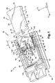
- la figure 1 est une vue schématique en perspective de trois-quarts avant qui illustre les principaux composants d'un agencement selon un mode de réalisation de l'invention et sur laquelle le support de données est illustré hors du boítier du dispositif d'échange de données ;
- la figure 2 est une vue en éclaté des principaux composants d'un dispositif d'échange de données selon le mode de réalisation de la figure 1 ;
- la figure 3 est une vue de dessus d'un agencement selon la figure 1 qui illustre l'accostage de l'organe de commande par le bord transversal avant du support de données en vue de son introduction dans le logement du boítier, l'organe de commande étant en position arrière de repos et l'organe de blocage en position escamotée ;
- la figure 4 est une vue similaire à celle de la figure 3, qui illustre un agencement dans lequel le support de données est partiellement introduit dans le logement et l'organe de commande est dans une position intermédiaire entre sa position arrière de repos et sa position extrême avant ;
- la figure 5 est une vue similaire à celle de la figure 4 qui illustre l'organe de commande au-delà de sa position intermédiaire, c'est-à-dire la position qu'il occupe lorsque l'organe de blocage quitte la position escamotée pour venir pincer latéralement le support de données dans la position intermédiaire de retenue ;
- la figure 6 est une vue similaire à celle de la figure 5 qui illustre l'organe de commande dans sa position extrême avant qui correspond, après avalement du support de données, à la position de blocage de l'organe de blocage avec le support de données en position active de lecture et dans laquelle il peut être maintenu par un organe commandé de verrouillage.
Claims (19)
- Agencement (10) pour l'échange de données entre un support de données rigide (12), ou semi-rigide, et un dispositif d'échange de données (14), notamment de lecture de données contenues dans le support, du type comportant un boítier (36) dans lequel le support (12) est introduit longitudinalement, manuellement d'arrière en avant, dans un logement (40) du boítier (36) dans lequel il occupe une position active déterminée, et du type dans lequel le dispositif (14) comporte un organe de blocage (80) qui est monté mobile longitudinalement par rapport au boítier (36,38) entre :caractérisé en ce que l'organe de blocage (80) est entraíné longitudinalement en translation vers l'avant au cours de l'introduction (I) du support de données (12) dans le logement (40) du boítier (36) et comporte un doigt de commande (90) formant suiveur de came qui coopère avec un profil de came (100) solidaire du boítier (36) pour provoquer automatiquement l'introduction du doigt de blocage (88) dans le cran (28) du support de données (12) dès que l'organe de blocage (80) atteint au moins une position longitudinale de retenue qui est intermédiaire entre la position escamotée et la position de blocage.une position de blocage dans laquelle il bloque longitudinalement le support de données (12) en position active dans le boítier (36) au moyen d'un doigt de blocage (88) qui est reçu dans un cran (28) complémentaire du support de données (12) ;et une position escamotée, vers laquelle il est rappelé élastiquement, qui permet l'extraction du support de données (12) hors du boítier (36),
- Agencement (10) selon la revendication 1, caractérisé en ce que le cran (28) complémentaire est réalisé dans au moins un bord longitudinal (20, 22) du support de données (12) et est ouvert transversalement pour recevoir le doigt de blocage (88).
- Agencement (10) selon l'une des revendications 1 ou 2, caractérisé en ce qu'il comporte un organe de commande (46) du déplacement de l'organe de blocage (80) qui est lié en translation, avec jeu longitudinal, à l'organe de blocage (80) et qui est monté mobile par rapport au boítier (36, 38) entre une position arrière de repos et une position avant de blocage.
- Agencement (10) selon la revendication 3, caractérisé en ce que le support de données (12) comporte un bord transversal avant (24) qui, lors de l'introduction dans le logement (40), coopère avec l'organe de commande (46) pour provoquer son déplacement de sa position arrière de repos jusqu'à une position correspondant au rattrapage du jeu longitudinal puis entraíner l'organe de blocage (80) vers sa position intermédiaire de retenue et enfin sa position de blocage.
- Agencement (10) selon l'une des revendications 3 ou 4, caractérisé en ce qu'il comporte un organe de rappel élastique (64) de l'organe de commande (80) vers sa position arrière de repos pour constituer au moins un organe d'éjection du support de données (12).
- Agencement (10) selon l'une des revendications 3 ou 4, caractérisé en ce que l'organe de commande (46) est rappelé élastiquement d'une part vers une position stable arrière de repos et, d'autre part, vers une position stable extrême avant, par un ressort bistable (64) qui constitue un moyen d'assistance automatique à l'introduction par effet d'avalement et à l'extraction par effet d'éjection du support de données (12).
- Agencement (10) selon l'une quelconque des revendications 3 à 6, caractérisé en ce qu'il comporte des moyens de butée arrière (42) solidaires du boítier (36) qui déterminent la position extrême avant de l'organe de commande (46) et/ou la position escamotée de l'organe de blocage (80).
- Agencement (10) selon l'une quelconque des revendications 3 à 7, caractérisé en ce que, en position arrière de repos, l'organe de commande (46) obture une fenêtre (44) d'introduction du support de données (12) dans le logement (40).
- Agencement (10) selon l'une quelconque des revendications 3 à 8, caractérisé en ce qu'il comporte des moyens de butée avant (108) solidaires du boítier (36) qui déterminent la position extrême arrière de repos de l'organe de commande (46) et/ou la position de blocage de l'organe de blocage (80).
- Agencement (10) selon l'une quelconque des revendications précédentes, caractérisé en ce que l'organe de blocage (80) comporte un bras latéral de blocage (82), d'orientation globalement longitudinale, dont une extrémité avant (86) est montée pivotante autour d'un axe globalement perpendiculaire au plan horizontal dans lequel est située la direction longitudinale d'introduction (I) du support de données (12) et dont l'extrémité arrière porte le doigt de blocage (88).
- Agencement (10) selon la revendication 10, caractérisé en ce que le doigt de commande (90) de l'organe de blocage (80) est sollicité en permanence par des moyens élastiques pour coopérer avec le profil de came (100).
- Agencement (10) selon la revendication 11, caractérisé en ce que les moyens élastiques consistent en une lame élastique transversalement formant le bras latéral de blocage (82).
- Agencement (10) selon l'une quelconque des revendications précédentes, caractérisé en ce que le profil de came (100) comporte une portion inclinée (102) formant rampe de commande du passage de la position escamotée à la position de retenue et de blocage de l'organe de blocage (80).
- Agencement (10) selon l'une quelconque des revendications précédentes, caractérisé en ce que le doigt de blocage (88) comporte un flanc transversal avant qui coopère avec un bord arrière (32) du cran (28) de forme complémentaire de manière à faciliter, lors de l'extraction du support de données (12), le passage de l'organe de blocage (80) de sa position de blocage à sa position escamotée.
- Agencement selon l'une quelconque des revendications précédentes, caractérisé en ce qu'en position active, au moins une partie arrière (34) du support de données (12) fait saillie hors du boítier (36) de manière à constituer une partie de préhension permettant de l'extraire hors du boítier (36).
- Agencement (10) selon l'une quelconque des revendications précédentes, caractérisé en ce que l'organe de blocage (80) présente une symétrie selon un plan vertical globalement perpendiculaire au plan horizontal dans lequel est située la direction longitudinale d'introduction (I) du support de données (12).
- Agencement selon l'une quelconque des revendications précédentes, caractérisé en ce que le dispositif comporte un organe (110) commandé de verrouillage de l'organe de commande (46) dans la position extrême avant ou de l'organe de blocage (80) dans la position de blocage, le support de données (12) étant en position active.
- Agencement selon la revendication précédente, caractérisé en ce que l'organe (110) commandé de verrouillage est un électroaimant dont le noyau mobile constitue un doigt de verrouillage (112) qui peut être commandé en saillie à l'extérieur du boítier de l'électroaimant pour s'étendre en regard d'une partie (58) de l'organe de commande (46) afin d'empêcher toute translation de ce dernier de sa position extrême avant de blocage vers sa position arrière de repos.
- Agencement selon l'une quelconque des revendications précédentes, caractérisé en ce qu'il équipe un véhicule automobile dont les fonctions d'antivol sont partiellement ou totalement assurées par traitement de données dont certaines, contenues dans le support de données (12), sont représentatives d'un utilisateur autorisé, ou d'un groupe d'utilisateurs autorisés, du véhicule.
Applications Claiming Priority (2)
| Application Number | Priority Date | Filing Date | Title |
|---|---|---|---|
| FR0304089A FR2853430B1 (fr) | 2003-04-02 | 2003-04-02 | Agencement pour le blocage d'un support de donnees dans un dispositif d'echange de donnees |
| FR0304089 | 2003-04-02 |
Publications (2)
| Publication Number | Publication Date |
|---|---|
| EP1467309A1 true EP1467309A1 (fr) | 2004-10-13 |
| EP1467309B1 EP1467309B1 (fr) | 2012-06-13 |
Family
ID=32865381
Family Applications (1)
| Application Number | Title | Priority Date | Filing Date |
|---|---|---|---|
| EP20040101338 Expired - Lifetime EP1467309B1 (fr) | 2003-04-02 | 2004-04-01 | Agencement pour le blocage d'un support de données dans un dispositif d'échange de données |
Country Status (2)
| Country | Link |
|---|---|
| EP (1) | EP1467309B1 (fr) |
| FR (1) | FR2853430B1 (fr) |
Citations (3)
| Publication number | Priority date | Publication date | Assignee | Title |
|---|---|---|---|---|
| US20010012712A1 (en) * | 2000-02-04 | 2001-08-09 | Alps Electric Co., Ltd | Card connector having IC card ejection mechanism |
| EP1162701A2 (fr) * | 2000-06-08 | 2001-12-12 | Hirose Electric Co., Ltd. | Connecteur de carte |
| US6332790B1 (en) * | 1999-12-27 | 2001-12-25 | Union Machinery Co., Ltd. | Card connector |
-
2003
- 2003-04-02 FR FR0304089A patent/FR2853430B1/fr not_active Expired - Fee Related
-
2004
- 2004-04-01 EP EP20040101338 patent/EP1467309B1/fr not_active Expired - Lifetime
Patent Citations (3)
| Publication number | Priority date | Publication date | Assignee | Title |
|---|---|---|---|---|
| US6332790B1 (en) * | 1999-12-27 | 2001-12-25 | Union Machinery Co., Ltd. | Card connector |
| US20010012712A1 (en) * | 2000-02-04 | 2001-08-09 | Alps Electric Co., Ltd | Card connector having IC card ejection mechanism |
| EP1162701A2 (fr) * | 2000-06-08 | 2001-12-12 | Hirose Electric Co., Ltd. | Connecteur de carte |
Also Published As
| Publication number | Publication date |
|---|---|
| FR2853430A1 (fr) | 2004-10-08 |
| FR2853430B1 (fr) | 2005-05-06 |
| EP1467309B1 (fr) | 2012-06-13 |
Similar Documents
| Publication | Publication Date | Title |
|---|---|---|
| EP0860904B1 (fr) | Connecteur pour le raccordement d'une carte à circuit(s) intégré(s) et boítier équipé d'un tel connecteur | |
| WO2015113934A1 (fr) | Connecteur et ensemble connecteur correspondant | |
| EP1003123B1 (fr) | Agencement pour le blocage d'un support de données dans un dispositif d'échange de données | |
| EP1382001A1 (fr) | Connecteur electrique pour carte | |
| EP0964358B1 (fr) | Agencement pour le blocage longitudinal d'un support de données dans un dispositif d'échange de données | |
| FR2793921A1 (fr) | Ensemble compact pour le raccordement d'une carte a circuit(s) integre(s) comportant des moyens d'ejection de la carte | |
| EP2456021A1 (fr) | Prise électrique comportant des montants latéraux mobiles en translation | |
| FR2844642A1 (fr) | Connecteur electrique pour une carte a memoire electronique a grande capacite de stockage | |
| EP1467309B1 (fr) | Agencement pour le blocage d'un support de données dans un dispositif d'échange de données | |
| FR2779254A1 (fr) | Connecteur pour le raccordement d'une carte a circuit(s) integre(s) comportant des moyens d'ejection automatique de la carte | |
| EP1473659B1 (fr) | Agencement pour le blocage d'un support de données dans un dispositif d'échange de données | |
| EP0964357B1 (fr) | Agencement pour le blocage d'un support de données dans un dispositif d'échange de données | |
| FR2722593A1 (fr) | Dispositif recepteur pour une carte a memoire electronique | |
| EP1445729B1 (fr) | Agencement pour le blocage d'un support de données dans un dispositif d'échange de données | |
| EP0785326B1 (fr) | Pène demi-tour pour serrure réversible et serrure réversible comportant un tel pène | |
| WO1995013589A1 (fr) | Connecteur electrique et lecteur de carte le comportant | |
| FR2658338A1 (fr) | Connecteur electrique pour carte portant un circuit. | |
| EP2257145B1 (fr) | Dispositif de connexion | |
| EP1091313A1 (fr) | Agencement pour la réception d'un support de données dans un dispositif d'échange de données comportant un support pivotant | |
| FR2793923A1 (fr) | Agencement perfectionne pour le blocage longitudinal d'un support de donnees rigide dans un dispositif d'echange de donnees | |
| FR2779561A1 (fr) | Agencement pour le blocage longitudinal d'un support de donnees rigide dans un dispositif d'echange de donnees | |
| WO2005075263A1 (fr) | Dispositif de demarrage moteur pour vehicule automobile | |
| FR2659919A1 (fr) | Boucle pour ceinture de securite d'un vehicule. | |
| FR2982219A1 (fr) | Mecanisme d'essuie-vitre permettant une reduction de volume de conditionnement et/ou un montage facilite | |
| FR2591648A1 (fr) | Verrou magnetique |
Legal Events
| Date | Code | Title | Description |
|---|---|---|---|
| PUAI | Public reference made under article 153(3) epc to a published international application that has entered the european phase |
Free format text: ORIGINAL CODE: 0009012 |
|
| AK | Designated contracting states |
Kind code of ref document: A1 Designated state(s): AT BE BG CH CY CZ DE DK EE ES FI FR GB GR HU IE IT LI LU MC NL PL PT RO SE SI SK TR |
|
| AX | Request for extension of the european patent |
Extension state: AL HR LT LV MK |
|
| 17P | Request for examination filed |
Effective date: 20050413 |
|
| AKX | Designation fees paid |
Designated state(s): AT BE BG CH CY CZ DE DK EE ES FI FR GB GR HU IE IT LI LU MC NL PL PT RO SE SI SK TR |
|
| RAP1 | Party data changed (applicant data changed or rights of an application transferred) |
Owner name: VALEO SECURITE HABITACLE |
|
| GRAP | Despatch of communication of intention to grant a patent |
Free format text: ORIGINAL CODE: EPIDOSNIGR1 |
|
| GRAS | Grant fee paid |
Free format text: ORIGINAL CODE: EPIDOSNIGR3 |
|
| GRAA | (expected) grant |
Free format text: ORIGINAL CODE: 0009210 |
|
| AK | Designated contracting states |
Kind code of ref document: B1 Designated state(s): AT BE BG CH CY CZ DE DK EE ES FI FR GB GR HU IE IT LI LU MC NL PL PT RO SE SI SK TR |
|
| REG | Reference to a national code |
Ref country code: GB Ref legal event code: FG4D Free format text: NOT ENGLISH |
|
| REG | Reference to a national code |
Ref country code: CH Ref legal event code: EP Ref country code: AT Ref legal event code: REF Ref document number: 562270 Country of ref document: AT Kind code of ref document: T Effective date: 20120615 |
|
| REG | Reference to a national code |
Ref country code: IE Ref legal event code: FG4D Free format text: LANGUAGE OF EP DOCUMENT: FRENCH |
|
| REG | Reference to a national code |
Ref country code: DE Ref legal event code: R096 Ref document number: 602004038166 Country of ref document: DE Effective date: 20120816 |
|
| REG | Reference to a national code |
Ref country code: NL Ref legal event code: VDEP Effective date: 20120613 |
|
| PG25 | Lapsed in a contracting state [announced via postgrant information from national office to epo] |
Ref country code: SE Free format text: LAPSE BECAUSE OF FAILURE TO SUBMIT A TRANSLATION OF THE DESCRIPTION OR TO PAY THE FEE WITHIN THE PRESCRIBED TIME-LIMIT Effective date: 20120613 Ref country code: FI Free format text: LAPSE BECAUSE OF FAILURE TO SUBMIT A TRANSLATION OF THE DESCRIPTION OR TO PAY THE FEE WITHIN THE PRESCRIBED TIME-LIMIT Effective date: 20120613 Ref country code: CY Free format text: LAPSE BECAUSE OF FAILURE TO SUBMIT A TRANSLATION OF THE DESCRIPTION OR TO PAY THE FEE WITHIN THE PRESCRIBED TIME-LIMIT Effective date: 20120613 |
|
| REG | Reference to a national code |
Ref country code: AT Ref legal event code: MK05 Ref document number: 562270 Country of ref document: AT Kind code of ref document: T Effective date: 20120613 |
|
| PG25 | Lapsed in a contracting state [announced via postgrant information from national office to epo] |
Ref country code: SI Free format text: LAPSE BECAUSE OF FAILURE TO SUBMIT A TRANSLATION OF THE DESCRIPTION OR TO PAY THE FEE WITHIN THE PRESCRIBED TIME-LIMIT Effective date: 20120613 Ref country code: GR Free format text: LAPSE BECAUSE OF FAILURE TO SUBMIT A TRANSLATION OF THE DESCRIPTION OR TO PAY THE FEE WITHIN THE PRESCRIBED TIME-LIMIT Effective date: 20120914 |
|
| PG25 | Lapsed in a contracting state [announced via postgrant information from national office to epo] |
Ref country code: RO Free format text: LAPSE BECAUSE OF FAILURE TO SUBMIT A TRANSLATION OF THE DESCRIPTION OR TO PAY THE FEE WITHIN THE PRESCRIBED TIME-LIMIT Effective date: 20120613 Ref country code: EE Free format text: LAPSE BECAUSE OF FAILURE TO SUBMIT A TRANSLATION OF THE DESCRIPTION OR TO PAY THE FEE WITHIN THE PRESCRIBED TIME-LIMIT Effective date: 20120613 Ref country code: SK Free format text: LAPSE BECAUSE OF FAILURE TO SUBMIT A TRANSLATION OF THE DESCRIPTION OR TO PAY THE FEE WITHIN THE PRESCRIBED TIME-LIMIT Effective date: 20120613 Ref country code: CZ Free format text: LAPSE BECAUSE OF FAILURE TO SUBMIT A TRANSLATION OF THE DESCRIPTION OR TO PAY THE FEE WITHIN THE PRESCRIBED TIME-LIMIT Effective date: 20120613 Ref country code: AT Free format text: LAPSE BECAUSE OF FAILURE TO SUBMIT A TRANSLATION OF THE DESCRIPTION OR TO PAY THE FEE WITHIN THE PRESCRIBED TIME-LIMIT Effective date: 20120613 |
|
| PG25 | Lapsed in a contracting state [announced via postgrant information from national office to epo] |
Ref country code: PL Free format text: LAPSE BECAUSE OF FAILURE TO SUBMIT A TRANSLATION OF THE DESCRIPTION OR TO PAY THE FEE WITHIN THE PRESCRIBED TIME-LIMIT Effective date: 20120613 Ref country code: PT Free format text: LAPSE BECAUSE OF FAILURE TO SUBMIT A TRANSLATION OF THE DESCRIPTION OR TO PAY THE FEE WITHIN THE PRESCRIBED TIME-LIMIT Effective date: 20121015 Ref country code: IT Free format text: LAPSE BECAUSE OF FAILURE TO SUBMIT A TRANSLATION OF THE DESCRIPTION OR TO PAY THE FEE WITHIN THE PRESCRIBED TIME-LIMIT Effective date: 20120613 |
|
| PG25 | Lapsed in a contracting state [announced via postgrant information from national office to epo] |
Ref country code: NL Free format text: LAPSE BECAUSE OF FAILURE TO SUBMIT A TRANSLATION OF THE DESCRIPTION OR TO PAY THE FEE WITHIN THE PRESCRIBED TIME-LIMIT Effective date: 20120613 |
|
| PLBE | No opposition filed within time limit |
Free format text: ORIGINAL CODE: 0009261 |
|
| STAA | Information on the status of an ep patent application or granted ep patent |
Free format text: STATUS: NO OPPOSITION FILED WITHIN TIME LIMIT |
|
| PG25 | Lapsed in a contracting state [announced via postgrant information from national office to epo] |
Ref country code: DK Free format text: LAPSE BECAUSE OF FAILURE TO SUBMIT A TRANSLATION OF THE DESCRIPTION OR TO PAY THE FEE WITHIN THE PRESCRIBED TIME-LIMIT Effective date: 20120613 Ref country code: ES Free format text: LAPSE BECAUSE OF FAILURE TO SUBMIT A TRANSLATION OF THE DESCRIPTION OR TO PAY THE FEE WITHIN THE PRESCRIBED TIME-LIMIT Effective date: 20120924 |
|
| 26N | No opposition filed |
Effective date: 20130314 |
|
| REG | Reference to a national code |
Ref country code: DE Ref legal event code: R097 Ref document number: 602004038166 Country of ref document: DE Effective date: 20130314 |
|
| PG25 | Lapsed in a contracting state [announced via postgrant information from national office to epo] |
Ref country code: BG Free format text: LAPSE BECAUSE OF FAILURE TO SUBMIT A TRANSLATION OF THE DESCRIPTION OR TO PAY THE FEE WITHIN THE PRESCRIBED TIME-LIMIT Effective date: 20120913 |
|
| BERE | Be: lapsed |
Owner name: VALEO SECURITE HABITACLE Effective date: 20130430 |
|
| PG25 | Lapsed in a contracting state [announced via postgrant information from national office to epo] |
Ref country code: MC Free format text: LAPSE BECAUSE OF FAILURE TO SUBMIT A TRANSLATION OF THE DESCRIPTION OR TO PAY THE FEE WITHIN THE PRESCRIBED TIME-LIMIT Effective date: 20120613 |
|
| REG | Reference to a national code |
Ref country code: CH Ref legal event code: PL |
|
| REG | Reference to a national code |
Ref country code: IE Ref legal event code: MM4A |
|
| PG25 | Lapsed in a contracting state [announced via postgrant information from national office to epo] |
Ref country code: LI Free format text: LAPSE BECAUSE OF NON-PAYMENT OF DUE FEES Effective date: 20130430 Ref country code: CH Free format text: LAPSE BECAUSE OF NON-PAYMENT OF DUE FEES Effective date: 20130430 Ref country code: BE Free format text: LAPSE BECAUSE OF NON-PAYMENT OF DUE FEES Effective date: 20130430 |
|
| PG25 | Lapsed in a contracting state [announced via postgrant information from national office to epo] |
Ref country code: IE Free format text: LAPSE BECAUSE OF NON-PAYMENT OF DUE FEES Effective date: 20130401 |
|
| PG25 | Lapsed in a contracting state [announced via postgrant information from national office to epo] |
Ref country code: TR Free format text: LAPSE BECAUSE OF FAILURE TO SUBMIT A TRANSLATION OF THE DESCRIPTION OR TO PAY THE FEE WITHIN THE PRESCRIBED TIME-LIMIT Effective date: 20120613 |
|
| PG25 | Lapsed in a contracting state [announced via postgrant information from national office to epo] |
Ref country code: LU Free format text: LAPSE BECAUSE OF NON-PAYMENT OF DUE FEES Effective date: 20130401 Ref country code: HU Free format text: LAPSE BECAUSE OF FAILURE TO SUBMIT A TRANSLATION OF THE DESCRIPTION OR TO PAY THE FEE WITHIN THE PRESCRIBED TIME-LIMIT; INVALID AB INITIO Effective date: 20040401 |
|
| REG | Reference to a national code |
Ref country code: FR Ref legal event code: PLFP Year of fee payment: 13 |
|
| REG | Reference to a national code |
Ref country code: FR Ref legal event code: PLFP Year of fee payment: 14 |
|
| REG | Reference to a national code |
Ref country code: FR Ref legal event code: PLFP Year of fee payment: 15 |
|
| PGFP | Annual fee paid to national office [announced via postgrant information from national office to epo] |
Ref country code: DE Payment date: 20180409 Year of fee payment: 15 |
|
| PGFP | Annual fee paid to national office [announced via postgrant information from national office to epo] |
Ref country code: FR Payment date: 20180426 Year of fee payment: 15 |
|
| PGFP | Annual fee paid to national office [announced via postgrant information from national office to epo] |
Ref country code: GB Payment date: 20180417 Year of fee payment: 15 |
|
| REG | Reference to a national code |
Ref country code: DE Ref legal event code: R119 Ref document number: 602004038166 Country of ref document: DE |
|
| GBPC | Gb: european patent ceased through non-payment of renewal fee |
Effective date: 20190401 |
|
| PG25 | Lapsed in a contracting state [announced via postgrant information from national office to epo] |
Ref country code: GB Free format text: LAPSE BECAUSE OF NON-PAYMENT OF DUE FEES Effective date: 20190401 Ref country code: DE Free format text: LAPSE BECAUSE OF NON-PAYMENT OF DUE FEES Effective date: 20191101 |
|
| PG25 | Lapsed in a contracting state [announced via postgrant information from national office to epo] |
Ref country code: FR Free format text: LAPSE BECAUSE OF NON-PAYMENT OF DUE FEES Effective date: 20190430 |