EP1466876A1 - Double glazing - Google Patents
Double glazing Download PDFInfo
- Publication number
- EP1466876A1 EP1466876A1 EP02783808A EP02783808A EP1466876A1 EP 1466876 A1 EP1466876 A1 EP 1466876A1 EP 02783808 A EP02783808 A EP 02783808A EP 02783808 A EP02783808 A EP 02783808A EP 1466876 A1 EP1466876 A1 EP 1466876A1
- Authority
- EP
- European Patent Office
- Prior art keywords
- glass
- bored
- lid member
- glass plate
- seal member
- Prior art date
- Legal status (The legal status is an assumption and is not a legal conclusion. Google has not performed a legal analysis and makes no representation as to the accuracy of the status listed.)
- Withdrawn
Links
- 239000011521 glass Substances 0.000 claims abstract description 139
- 239000011800 void material Substances 0.000 claims abstract description 26
- 238000007789 sealing Methods 0.000 claims abstract description 11
- 239000000463 material Substances 0.000 claims abstract description 10
- 238000002844 melting Methods 0.000 claims description 21
- 230000000452 restraining effect Effects 0.000 abstract description 4
- 239000007789 gas Substances 0.000 description 12
- 230000008018 melting Effects 0.000 description 9
- 238000000034 method Methods 0.000 description 7
- 238000010438 heat treatment Methods 0.000 description 6
- 125000006850 spacer group Chemical group 0.000 description 6
- 230000008602 contraction Effects 0.000 description 5
- 230000002093 peripheral effect Effects 0.000 description 5
- VYPSYNLAJGMNEJ-UHFFFAOYSA-N Silicium dioxide Chemical compound O=[Si]=O VYPSYNLAJGMNEJ-UHFFFAOYSA-N 0.000 description 3
- 239000005388 borosilicate glass Substances 0.000 description 3
- 238000010276 construction Methods 0.000 description 3
- 238000001816 cooling Methods 0.000 description 3
- 230000006837 decompression Effects 0.000 description 3
- 230000000694 effects Effects 0.000 description 3
- 238000004519 manufacturing process Methods 0.000 description 3
- 239000002184 metal Substances 0.000 description 3
- 239000005361 soda-lime glass Substances 0.000 description 3
- 239000000919 ceramic Substances 0.000 description 2
- 239000005357 flat glass Substances 0.000 description 2
- 239000005329 float glass Substances 0.000 description 2
- 238000009413 insulation Methods 0.000 description 2
- 229910000679 solder Inorganic materials 0.000 description 2
- CDBYLPFSWZWCQE-UHFFFAOYSA-L Sodium Carbonate Chemical compound [Na+].[Na+].[O-]C([O-])=O CDBYLPFSWZWCQE-UHFFFAOYSA-L 0.000 description 1
- UCKMPCXJQFINFW-UHFFFAOYSA-N Sulphide Chemical compound [S-2] UCKMPCXJQFINFW-UHFFFAOYSA-N 0.000 description 1
- 239000005354 aluminosilicate glass Substances 0.000 description 1
- 238000007496 glass forming Methods 0.000 description 1
- 239000005346 heat strengthened glass Substances 0.000 description 1
- 229910000816 inconels 718 Inorganic materials 0.000 description 1
- 239000000203 mixture Substances 0.000 description 1
- 238000009304 pastoral farming Methods 0.000 description 1
- 230000035699 permeability Effects 0.000 description 1
- 229910001220 stainless steel Inorganic materials 0.000 description 1
- 239000010935 stainless steel Substances 0.000 description 1
- 230000001629 suppression Effects 0.000 description 1
- 238000004381 surface treatment Methods 0.000 description 1
- 239000005341 toughened glass Substances 0.000 description 1
- XLYOFNOQVPJJNP-UHFFFAOYSA-N water Substances O XLYOFNOQVPJJNP-UHFFFAOYSA-N 0.000 description 1
Images


Classifications
-
- E—FIXED CONSTRUCTIONS
- E06—DOORS, WINDOWS, SHUTTERS, OR ROLLER BLINDS IN GENERAL; LADDERS
- E06B—FIXED OR MOVABLE CLOSURES FOR OPENINGS IN BUILDINGS, VEHICLES, FENCES OR LIKE ENCLOSURES IN GENERAL, e.g. DOORS, WINDOWS, BLINDS, GATES
- E06B3/00—Window sashes, door leaves, or like elements for closing wall or like openings; Layout of fixed or moving closures, e.g. windows in wall or like openings; Features of rigidly-mounted outer frames relating to the mounting of wing frames
- E06B3/66—Units comprising two or more parallel glass or like panes permanently secured together
- E06B3/6612—Evacuated glazing units
-
- C—CHEMISTRY; METALLURGY
- C03—GLASS; MINERAL OR SLAG WOOL
- C03C—CHEMICAL COMPOSITION OF GLASSES, GLAZES OR VITREOUS ENAMELS; SURFACE TREATMENT OF GLASS; SURFACE TREATMENT OF FIBRES OR FILAMENTS MADE FROM GLASS, MINERALS OR SLAGS; JOINING GLASS TO GLASS OR OTHER MATERIALS
- C03C27/00—Joining pieces of glass to pieces of other inorganic material; Joining glass to glass other than by fusing
- C03C27/06—Joining glass to glass by processes other than fusing
-
- E—FIXED CONSTRUCTIONS
- E06—DOORS, WINDOWS, SHUTTERS, OR ROLLER BLINDS IN GENERAL; LADDERS
- E06B—FIXED OR MOVABLE CLOSURES FOR OPENINGS IN BUILDINGS, VEHICLES, FENCES OR LIKE ENCLOSURES IN GENERAL, e.g. DOORS, WINDOWS, BLINDS, GATES
- E06B3/00—Window sashes, door leaves, or like elements for closing wall or like openings; Layout of fixed or moving closures, e.g. windows in wall or like openings; Features of rigidly-mounted outer frames relating to the mounting of wing frames
- E06B3/66—Units comprising two or more parallel glass or like panes permanently secured together
- E06B3/677—Evacuating or filling the gap between the panes ; Equilibration of inside and outside pressure; Preventing condensation in the gap between the panes; Cleaning the gap between the panes
- E06B3/6775—Evacuating or filling the gap during assembly
-
- Y—GENERAL TAGGING OF NEW TECHNOLOGICAL DEVELOPMENTS; GENERAL TAGGING OF CROSS-SECTIONAL TECHNOLOGIES SPANNING OVER SEVERAL SECTIONS OF THE IPC; TECHNICAL SUBJECTS COVERED BY FORMER USPC CROSS-REFERENCE ART COLLECTIONS [XRACs] AND DIGESTS
- Y02—TECHNOLOGIES OR APPLICATIONS FOR MITIGATION OR ADAPTATION AGAINST CLIMATE CHANGE
- Y02A—TECHNOLOGIES FOR ADAPTATION TO CLIMATE CHANGE
- Y02A30/00—Adapting or protecting infrastructure or their operation
- Y02A30/24—Structural elements or technologies for improving thermal insulation
- Y02A30/249—Glazing, e.g. vacuum glazing
-
- Y—GENERAL TAGGING OF NEW TECHNOLOGICAL DEVELOPMENTS; GENERAL TAGGING OF CROSS-SECTIONAL TECHNOLOGIES SPANNING OVER SEVERAL SECTIONS OF THE IPC; TECHNICAL SUBJECTS COVERED BY FORMER USPC CROSS-REFERENCE ART COLLECTIONS [XRACs] AND DIGESTS
- Y02—TECHNOLOGIES OR APPLICATIONS FOR MITIGATION OR ADAPTATION AGAINST CLIMATE CHANGE
- Y02B—CLIMATE CHANGE MITIGATION TECHNOLOGIES RELATED TO BUILDINGS, e.g. HOUSING, HOUSE APPLIANCES OR RELATED END-USER APPLICATIONS
- Y02B80/00—Architectural or constructional elements improving the thermal performance of buildings
- Y02B80/22—Glazing, e.g. vaccum glazing
Definitions
- the thermally meltable seal member is melted by heating and is subsequently hardened by cooling, thereby to adhere the lid member placed on the thermally meltable seal member to the bored glass plate to seal the communicating bore.
- the thermal expansion of the bored glass plate and the lid member Conventionally, no special consideration has been made as to the thermal expansion of the bored glass plate and the lid member.
- the thermally meltable seal member 7 When the thermally meltable seal member 7 is cooled in this condition to harden at approximately 380°C, for example, and adhere the lid member 6 to the bored glass plate 1, the lid member 6 and the bored glass plate 1 restrain each other from thermally contracting.
- the thermal construction of the lid member 6 When further cooled to room temperature while restraining each other from thermally contracting, the thermal construction of the lid member 6 is suppressed by the bored glass plate 1 and the lid member 6 is unable to contract to the position T as shown in (b).
- a tensile stress W2 corresponding to t2 is produced adjacent surfaces of the bored glass plate 1 where the thermally meltable seal member 7 is adhered.
- a glass plate has a property of being relatively strong against compressive stress but relatively vulnerable to tensile stress.
- the bored glass plate 1 where the tensile stress W2 is produced may suffer cracks and breaks adjacent portions where the lid member 6 is adhered.
- the present invention has been made having regard to the conventional problems described above, and its object is to provide a glass panel capable of restraining cracks and breaks from generating in a bored glass plate when a lid member is adhered to the bored glass plate by a thermally meltable seal member.
- the present invention defined in Claim 1 is characterized by a glass panel P comprising a pair of glass plates 1 and 2 opposed to each other with a void V defined therebetween, a joining seal member 4 for joining and sealing the glass plates 1 and 2 at peripheries thereof, a communicating bore 5 formed in one of the glass plates 1 and 2 for communicating with the void V, and a lid member 6 adhered to the bored glass plate 1 having the communicating bore 5 by a thermally meltable seal member 7 to seal the communicating bore 5, wherein the lid member 6 is made of a material having a thermal expansion coefficient ⁇ smaller than a thermal expansion coefficient ⁇ of the bored glass plate 1.
- the present invention defined in Claim 2 is characterized in that the thermally meltable seal member 7 is made of a material having a thermal expansion coefficient ⁇ smaller than the thermal expansion coefficient ⁇ of the bored glass plate 1 and greater than the thermal expansion coefficient ⁇ of the lid member 6.
- the present invention defined in Claim 4 is characterized in that the void V is decompressed.
- the lid member for sealing the communicating bore formed in the bored glass plate by being adhered thereto through the thermally meltable seal member is made of the material having the thermal expansion coefficient smaller than the bored glass plate.
- the thermal expansion of the lid member is relatively restricted to a small amount compared with that of the bored glass plate.
- the vicinity of the communicating bore of the bored glass plate is restrained from thermally expanding by the peripheral portions thereof as noted above, and thus has a small amount of thermal expansion compared with an inherent amount of thermal expansion thereof.
- the thermally meltable seal member is made of a material having a thermal expansion coefficient smaller than that of the bored glass plate and greater than that of the lid member.
- the thermal expansion coefficient of the thermally meltable seal member falls between the thermal expansion coefficient of the bored glass plate and the thermal expansion coefficient of the lid member.
- the thermally meltable seal member bears part of the tensile stress generated with thermal contraction of the lid member.
- the tensile stress generated in the bored glass plate is reduced by a corresponding amount, which can more effectively restrain cracks and breaks from generating in the portions of the bored glass plate where the lid member is adhered.
- the lid member is made of glass while the thermally meltable seal member is made of low temperature-melting glass.
- the lid member and the thermally meltable seal member are made of glass in addition to the pair of glass plates constituting the glass panel. This realizes good adhesion between these three components. Further, the thermally meltable seal member has a low temperature melting point and the heating temperature for adhesion can be lowered. Thus, it is possible to reduce the tensile stress per se generated in the thermally meltable seal member and the bored glass plate with thermal contraction of the lid member, thereby to more reliably restrain cracks and breaks from generating in the bored glass plate.
- a vacuum double glazing P comprises a pair of glass plates 1 and 2 and numerous spacers 3 arranged therebetween.
- the glass plates 1 and 2 are arranged opposite each other with a void V defined therebetween.
- Both of the glass plates 1 and 2 are joined at peripheries thereof by a joining seal member 4 in the form of low temperature-melting glass having a lower melting point than the glass plates 1 and 2, and low gas permeability, with the void V between the glass plates 1 and 2 being sealed in a decompressed condition.
- Float glass plates in the form of transparent soda lime glass approximately 2.65 to 3.2mm thick are used as the glass plates 1 and 2.
- the void V defined between the glass plates 1 and 2 is decompressed to 1.33Pa (1.0 ⁇ 10 -2 Torr) or less.
- one of the glass plates 1 has a suction bore 5 formed therein and having a circular section which is one example of communicating bores to communicate with the void V in order to decompress the void V by drawing and removing gas therefrom.
- the suction bore 5 acts also as a getter accommodating space for accommodating a cylindrical getter G.
- the suction bore 5 accommodates the getter G, and the suction bore 5 is sealed by a circular lid member 6 made of transparent flat glass rigidly adhered to the bored glass plate 1 having the suction bore 5 by a thermally meltable seal member 7.
- borosilicate glass As the lid member 6 for sealing the suction bore 5, borosilicate glass is used having a thermal expansion coefficient ⁇ smaller than a thermal expansion coefficient ⁇ of the soda lime glass used as the bored glass plate 1.
- the lid member 6 is rigidly adhered to the bored glass plate 1 by the thermally meltable seal member 7 made of low temperature-melting glass having a higher melting point than the low temperature-melting glass forming the joining seal member 4, and having a lower melting point than the lid member 6 and the bored glass plate 1.
- the spacers 3 preferably have a cylindrical configuration. They are made of a material having a compressive strength of at least 4.9 ⁇ 10 8 Pa (5 ⁇ 10 3 kgf/cm 2 ), e.g. stainless steel (SUS304), Inconel 718 or the like, to be capable of enduring atmospheric pressure acting on both of the glass plates 1 and 2.
- the spacers 3 are about 0.3 to 1.0mm in diameter and about 0.15 to 1.0mm in height. The intervals between the spacers 3 are set to about 20mm.
- the glass plates 1 and 2 in a substantially horizontal position are placed in an unillustrated heating furnace.
- the joining seal member 4 is melted by baking to execute a joining process for joining the glass plates 1 and 2 at the peripheries thereof by the melted joining seal member 4 to seal the void V.
- the entire lid member 6 is also heated to approximately 400°C as the thermally meltable seal member 7 is heated and melted.
- the vicinity of the suction bore 5 is heated to approximately 400°C, while the peripheral portions remote from the suction bore 5 are heated to approximately 180°C.
- the lid member 6 thermally expands relative to a room temperature position indicated as T by an amount corresponding to the heating temperature.
- the vicinity of the suction bore 5 in the bored glass plate 1 is restrained by the peripheral portions thereof and thus not allowed to thermally expand by an amount corresponding to the heating temperature.
- the relationship ⁇ is established between the thermal expansion coefficient ⁇ of the lid member 6 and the thermal expansion coefficient ⁇ of the bored glass plate 1, the amounts of thermal expansion of the lid member 6 and the vicinity of the suction bore 5 in the bored glass plate 1 approximate each other.
- the present invention provides a glass panel capable of restraining cracks and breaks from generating in a bored glass plate when a lid member is adhered to the bored glass plate by a thermally meltable seal member.
Landscapes
- Engineering & Computer Science (AREA)
- Chemical & Material Sciences (AREA)
- Civil Engineering (AREA)
- Structural Engineering (AREA)
- Ceramic Engineering (AREA)
- Life Sciences & Earth Sciences (AREA)
- Chemical Kinetics & Catalysis (AREA)
- General Chemical & Material Sciences (AREA)
- Geochemistry & Mineralogy (AREA)
- Materials Engineering (AREA)
- Organic Chemistry (AREA)
- Joining Of Glass To Other Materials (AREA)
Abstract
A glass panel (P) comprising a pair of glass plates (1, 2) opposed to each
other with a void (V) defined therebetween, a joining seal member for
joining and sealing the glass plates (1, 2) at peripheries thereof, a
communicating bore (5) formed in one of the glass plates (1, 2) for
communicating with the void (V), and a lid member (6) adhered to the
bored glass plate (1) having the communicating bore (5) by a thermally
meltable seal member (7) to seal the communicating bore (5). The lid
member (6) is made of a material having a thermal expansion coefficient
α smaller than a thermal expansion coefficient γ of the bored glass plate
(1). The glass panel is capable of restraining cracks and breaks from
generating in the bored glass plate when the lid member is adhered to
the bored glass plate by the thermally meltable seal member.
Description
The present invention relates to a glass panel comprising a pair of glass
plates opposed to each other and defining a void therebetween, a joining
seal member for joining and sealing the glass plates at peripheries
thereof, a communicating bore formed in one of the glass plates to
communicate with the void, and a lid member adhered to the bored
glass plate having the communicating bore by a thermally meltable seal
member thereby to seal the communicating bore.
In this type of glass panel, the thermally meltable seal member is
melted by heating and is subsequently hardened by cooling, thereby to
adhere the lid member placed on the thermally meltable seal member to
the bored glass plate to seal the communicating bore. Conventionally,
no special consideration has been made as to the thermal expansion of
the bored glass plate and the lid member.
Thus, as shown in Fig. 5, where low temperature-melting glass which is
meltable at 400°C or above is used as the thermally meltable seal
member 7, the low temperature-melting glass needs to be heated to
400°C or above. The lid member 6 placed over the low
temperature-melting glass is also heated as a whole to nearly 400°C and
thermally expands relative to a room temperature position indicated by
T by an amount corresponding to the heating temperature as shown in
(a).
With the bored glass plate 1, however, only the vicinity of the
communicating bore 5 is locally heated to nearly 400°C, and peripheral
portions remote from the communicating bore 5 are heated only to a
lower temperature, e.g. no more than approximately180°C. As a result,
the vicinity of the communicating bore 5 is restrained from thermally
expanding by the peripheral portions and is unable to thermally expand
by an amount corresponding to the temperature of 400°C. Thus, an
amount of thermal expansion of the vicinity of the bore becomes smaller
than the amount of thermal expansion of the lid member 6.
When the thermally meltable seal member 7 is cooled in this condition
to harden at approximately 380°C, for example, and adhere the lid
member 6 to the bored glass plate 1, the lid member 6 and the bored
glass plate 1 restrain each other from thermally contracting. When
further cooled to room temperature while restraining each other from
thermally contracting, the thermal construction of the lid member 6 is
suppressed by the bored glass plate 1 and the lid member 6 is unable to
contract to the position T as shown in (b). As a result of the
suppression of the thermal contraction by an amount indicated at t2, a
tensile stress W2 corresponding to t2 is produced adjacent surfaces of
the bored glass plate 1 where the thermally meltable seal member 7 is
adhered.
However, a glass plate has a property of being relatively strong against
compressive stress but relatively vulnerable to tensile stress. Thus, the
bored glass plate 1 where the tensile stress W2 is produced may suffer
cracks and breaks adjacent portions where the lid member 6 is adhered.
The present invention has been made having regard to the conventional
problems described above, and its object is to provide a glass panel
capable of restraining cracks and breaks from generating in a bored
glass plate when a lid member is adhered to the bored glass plate by a
thermally meltable seal member.
As shown in Figs. 1 through 4, the present invention defined in Claim 1
is characterized by a glass panel P comprising a pair of glass plates 1
and 2 opposed to each other with a void V defined therebetween, a
joining seal member 4 for joining and sealing the glass plates 1 and 2 at
peripheries thereof, a communicating bore 5 formed in one of the glass
plates 1 and 2 for communicating with the void V, and a lid member 6
adhered to the bored glass plate 1 having the communicating bore 5 by a
thermally meltable seal member 7 to seal the communicating bore 5,
wherein the lid member 6 is made of a material having a thermal
expansion coefficient α smaller than a thermal expansion coefficient γ of
the bored glass plate 1.
As shown in Figs. 1 through 4, the present invention defined in Claim 2
is characterized in that the thermally meltable seal member 7 is made
of a material having a thermal expansion coefficient β smaller than the
thermal expansion coefficient γ of the bored glass plate 1 and greater
than the thermal expansion coefficient α of the lid member 6.
As shown in Figs. 1 through 4, the present invention defined in Claim 3
is characterized in that the lid member 6 is made of glass, and the
thermally meltable seal member 7 is made of low temperature-melting
glass.
As shown in Fig. 1 through 4, the present invention defined in Claim 4
is characterized in that the void V is decompressed.
While the above description includes reference numbers and symbols for
expediency of comparison to the drawings, such inclusion does not limit
the present invention to the constructions shown in the accompanying
drawings.
According to the characteristic feature of the present invention defined
in Claim 1, the lid member for sealing the communicating bore formed
in the bored glass plate by being adhered thereto through the thermally
meltable seal member is made of the material having the thermal
expansion coefficient smaller than the bored glass plate. Thus, as the
thermally meltable seal member is heated to a melting temperature for
adhering the lid member, the thermal expansion of the lid member is
relatively restricted to a small amount compared with that of the bored
glass plate. On the other hand, the vicinity of the communicating bore
of the bored glass plate is restrained from thermally expanding by the
peripheral portions thereof as noted above, and thus has a small amount
of thermal expansion compared with an inherent amount of thermal
expansion thereof.
Thus, even when the lid member is adhered to the bored glass plate by
cooling of the thermally meltable seal member in this condition and
further cooled to room temperature with the lid member and bored glass
plate being restrained from thermally contracting with each other,
amounts of thermal contraction of the lid member and the vicinity of the
communicating bore are relatively approximate to each other. As a
result, tensile stress generated in the bored glass plate is relatively
small, which can effectively restrain cracks and breaks from generating
in portions of the bored glass plate where the lid member is adhered.
According to the characteristic feature of the present invention defined
in Claim 2, the thermally meltable seal member is made of a material
having a thermal expansion coefficient smaller than that of the bored
glass plate and greater than that of the lid member. In other words,
the thermal expansion coefficient of the thermally meltable seal member
falls between the thermal expansion coefficient of the bored glass plate
and the thermal expansion coefficient of the lid member. Thus, when
the thermally meltable seal member is heated to the melting
temperature, an amount of thermal expansion of the thermally meltable
seal member falls between the amount of thermal expansion of the lid
member and the amount of thermal expansion of the bored glass plate.
Thus, when the lid member is adhered to the bored glass plate by
cooling of the thermally meltable seal member in this condition and
further cooled to room temperature with the lid member, thermally
meltable seal member and bored glass plate being restrained from
thermal contracting with one another, the thermally meltable seal
member bears part of the tensile stress generated with thermal
contraction of the lid member. Hence, the tensile stress generated in
the bored glass plate is reduced by a corresponding amount, which can
more effectively restrain cracks and breaks from generating in the
portions of the bored glass plate where the lid member is adhered.
According to the characteristic feature of the present invention defined
in Claim 3, the lid member is made of glass while the thermally
meltable seal member is made of low temperature-melting glass. The
lid member and the thermally meltable seal member are made of glass
in addition to the pair of glass plates constituting the glass panel. This
realizes good adhesion between these three components. Further, the
thermally meltable seal member has a low temperature melting point
and the heating temperature for adhesion can be lowered. Thus, it is
possible to reduce the tensile stress per se generated in the thermally
meltable seal member and the bored glass plate with thermal
contraction of the lid member, thereby to more reliably restrain cracks
and breaks from generating in the bored glass plate.
According to the characteristic feature of the present invention defined
in Claim 4, since the void between the glass plates is decompressed, a
heat-insulation effect by decompression can be expected. Further, as
noted above, it is possible to provide the glass panel having less
possibility of suffering cracks and breaks and having an excellent
heat-insulation effect.
An embodiment of a vacuum double glazing exemplifying a glass panel
according to the present invention will be described hereinafter with
reference to the drawings.
As illustrated in Fig. 1, a vacuum double glazing P comprises a pair of
glass plates 1 and 2 and numerous spacers 3 arranged therebetween.
Thus, the glass plates 1 and 2 are arranged opposite each other with a
void V defined therebetween. Both of the glass plates 1 and 2 are
joined at peripheries thereof by a joining seal member 4 in the form of
low temperature-melting glass having a lower melting point than the
glass plates 1 and 2, and low gas permeability, with the void V between
the glass plates 1 and 2 being sealed in a decompressed condition.
Float glass plates in the form of transparent soda lime glass
approximately 2.65 to 3.2mm thick are used as the glass plates 1 and 2.
The void V defined between the glass plates 1 and 2 is decompressed to
1.33Pa (1.0×10⁻²Torr) or less.
A decompression process for the void V will be described in detail later.
As illustrated in Figs. 2 and 3, one of the glass plates 1 has a suction
bore 5 formed therein and having a circular section which is one
example of communicating bores to communicate with the void V in
order to decompress the void V by drawing and removing gas therefrom.
The suction bore 5 acts also as a getter accommodating space for
accommodating a cylindrical getter G. The suction bore 5
accommodates the getter G, and the suction bore 5 is sealed by a
circular lid member 6 made of transparent flat glass rigidly adhered to
the bored glass plate 1 having the suction bore 5 by a thermally
meltable seal member 7.
As the lid member 6 for sealing the suction bore 5, borosilicate glass is
used having a thermal expansion coefficient α smaller than a thermal
expansion coefficient γ of the soda lime glass used as the bored glass
plate 1. The lid member 6 is rigidly adhered to the bored glass plate 1
by the thermally meltable seal member 7 made of low
temperature-melting glass having a higher melting point than the low
temperature-melting glass forming the joining seal member 4, and
having a lower melting point than the lid member 6 and the bored glass
plate 1.
As the thermally meltable seal member 7, low temperature melting
glass is selected having a thermal expansion coefficient β smaller than
the thermal expansion coefficient γ of the bored glass plate 1 and greater
than the thermal expansion coefficient α of the lid member 6, where a
relationship α<β<γ is established between the thermal expansion
coefficient α of the lid member 6, the thermal expansion coefficient β of
the thermally meltable seal member 7 and the thermal expansion
coefficient γ of the bored glass plate 1.
The lid member 6 is approximately 20mm in diameter where the suction
bore 5 12mm in diameter accommodates the getter 10mm in diameter,
for example.
The spacers 3 preferably have a cylindrical configuration. They are
made of a material having a compressive strength of at least 4.9×10⁸Pa
(5×10³kgf/cm2), e.g. stainless steel (SUS304), Inconel 718 or the like, to
be capable of enduring atmospheric pressure acting on both of the glass
plates 1 and 2. In the case of the cylindrical configuration, the spacers
3 are about 0.3 to 1.0mm in diameter and about 0.15 to 1.0mm in height.
The intervals between the spacers 3 are set to about 20mm.
Next, a process for manufacturing the vacuum double glazing P will be
described.
First, one of the glass plates 2 not having the suction bore 5 formed
therein is supported in a substantially horizontal position. The joining
seal member 4 made of paste-like low temperature-melting glass is
applied to a top surface of the glass plate at the peripheries thereof, and
the numerous spacers 3 are arranged at predetermined intervals.
Then, thebored glass plate 1 is placed over the spacers. In this
arrangement, the lower glass plate 2 has a slightly larger area such that
the peripheries of the lower glass plate may protrude from the
peripheries of the upper bored glass plate 1. This is convenient for
application of the joining seal member 4.
Then, the
The glass plates 1 and 2 in a substantially horizontal position are placed
in an unillustrated heating furnace. The joining seal member 4 is
melted by baking to execute a joining process for joining the glass plates
1 and 2 at the peripheries thereof by the melted joining seal member 4
to seal the void V.
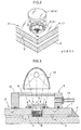
Then, as shown in Fig. 2, the getter G is inserted into the suction bore 5
of the bored glass plate 1. Around the suction bore 5 of the bored glass
plate 1 is placed the annular thermally meltable seal member 7, and the
lid member 6 is placed on the thermally meltable seal member 7. A
plurality of suction recesses 7a are formed peripherally of the thermally
meltable seal member 7. Gas can be drawn and removed from the void
V through the suction recesses 7a. With this arrangement, a suction
sealing device 8 is placed from above as shown in Fig. 3.
The suction sealing device 8 includes a tubular suction cup 10 closed by
transparent silica glass 9 at a top thereof. The suction cup 10 includes
a flexible suction pipe 11 communicating with an interior space of the
suction cup 10, and an O-ring 12 provided in a lower surface thereof for
sealing the top surface of the bored glass plate 1. A heat source 13 in
the form of a lamp, laser-beam generator or the like is provided on an
outer upper surface of the silica glass 9 of the suction cup 10.
While the void V is gradually heated with the bored glass plate 1 being
covered with the suction sealing device 8, the interior of the suction cup
10 is decompressed by using an unillustrated rotary pump or a turbo
molecular pump connected to the flexible pipe 11 thereby to execute a
baking process for drawing and removing gas from the void V through
the suction bore 5 and further decompress the interior of the void V to
1.33 Pa or less.
During the decompressing process, the thermally meltable seal member
7 is locally heated by the heat source 13 to 400°C or above, for example,
to be melted thereby to adhere the lid member 6 to the bored glass plate
1.
At about the time the void V is decompressed to a predetermined
pressure, the getter G is also heated and activated. Then, water and
gases such as CO, CO2, N2, H2, O2, namely various gases such as oxide
gas, sulfide gas, carbide gas and organic gas that have not been drawn
in the baking process are adsorbed and removed.
The entire lid member 6 is also heated to approximately 400°C as the
thermally meltable seal member 7 is heated and melted. In the bored
glass plate 1, the vicinity of the suction bore 5 is heated to
approximately 400°C, while the peripheral portions remote from the
suction bore 5 are heated to approximately 180°C.
At this time, as shown in Fig. 4(a), the lid member 6 thermally expands
relative to a room temperature position indicated as T by an amount
corresponding to the heating temperature. The vicinity of the suction
bore 5 in the bored glass plate 1 is restrained by the peripheral portions
thereof and thus not allowed to thermally expand by an amount
corresponding to the heating temperature. However, since the
relationship α<γ is established between the thermal expansion
coefficient α of the lid member 6 and the thermal expansion coefficient γ
of the bored glass plate 1, the amounts of thermal expansion of the lid
member 6 and the vicinity of the suction bore 5 in the bored glass plate
1 approximate each other.
Thus, even when the lid member 6 is adhered to the bored glass plate 1
by hardening of the melted thermally meltable seal member 7 and
further cooled to room temperature to thermally contract, the amounts
of thermal contraction of the lid member 6 and the vicinity of the suction
bore 5 in the bored glass plate 1 approximate each other. For example,
the lid member 6 is restrained from thermally contracting only by an
amount indicated by t1 in Fig. 4(b). As a result, tensile stress W1
generated in the bored glass plate 1 becomes relatively small.
The present invention provides a glass panel capable of restraining
cracks and breaks from generating in a bored glass plate when a lid
member is adhered to the bored glass plate by a thermally meltable seal
member.
Claims (4)
- A glass panel comprising a pair of glass plates opposed to each other with a void defined therebetween, a joining seal member for joining and sealing the glass plates at peripheries thereof, a communicating bore formed in one of the glass plates for communicating with the void, and a lid member adhered to the bored glass plate having the communicating bore by a thermally meltable seal member to seal the communicating bore, wherein the lid member is made of a material having a thermal expansion coefficient smaller than a thermal expansion coefficient of the bored glass plate.
- A glass panel as claimed in Claim 1, wherein the thermally meltable seal member is made of a material having a thermal expansion coefficient smaller than the thermal expansion coefficient of the bored glass plate and greater than the thermal expansion coefficient of the lid member.
- A glass panel as claimed in Claim 2, wherein the lid member is made of glass, and the thermally meltable seal member is made of low temperature-melting glass.
- A glass panel as claimed in any one of Claims 1 through 3, wherein the void is decompressed.
Applications Claiming Priority (3)
| Application Number | Priority Date | Filing Date | Title |
|---|---|---|---|
| JP2001391998 | 2001-12-25 | ||
| JP2001391998A JP2003192400A (en) | 2001-12-25 | 2001-12-25 | Glass panel |
| PCT/JP2002/012878 WO2003055819A1 (en) | 2001-12-25 | 2002-12-09 | Double glazing |
Publications (1)
| Publication Number | Publication Date |
|---|---|
| EP1466876A1 true EP1466876A1 (en) | 2004-10-13 |
Family
ID=19188584
Family Applications (1)
| Application Number | Title | Priority Date | Filing Date |
|---|---|---|---|
| EP02783808A Withdrawn EP1466876A1 (en) | 2001-12-25 | 2002-12-09 | Double glazing |
Country Status (6)
| Country | Link |
|---|---|
| US (1) | US7045181B2 (en) |
| EP (1) | EP1466876A1 (en) |
| JP (1) | JP2003192400A (en) |
| KR (1) | KR20040074057A (en) |
| CN (1) | CN1278976C (en) |
| WO (1) | WO2003055819A1 (en) |
Families Citing this family (69)
| Publication number | Priority date | Publication date | Assignee | Title |
|---|---|---|---|---|
| US6627814B1 (en) * | 2002-03-22 | 2003-09-30 | David H. Stark | Hermetically sealed micro-device package with window |
| US20060191215A1 (en) * | 2002-03-22 | 2006-08-31 | Stark David H | Insulated glazing units and methods |
| US6962834B2 (en) * | 2002-03-22 | 2005-11-08 | Stark David H | Wafer-level hermetic micro-device packages |
| US7832177B2 (en) | 2002-03-22 | 2010-11-16 | Electronics Packaging Solutions, Inc. | Insulated glazing units |
| US7599861B2 (en) | 2006-03-02 | 2009-10-06 | Convergys Customer Management Group, Inc. | System and method for closed loop decisionmaking in an automated care system |
| US7809663B1 (en) | 2006-05-22 | 2010-10-05 | Convergys Cmg Utah, Inc. | System and method for supporting the utilization of machine language |
| US8379830B1 (en) | 2006-05-22 | 2013-02-19 | Convergys Customer Management Delaware Llc | System and method for automated customer service with contingent live interaction |
| US7989040B2 (en) * | 2007-09-14 | 2011-08-02 | Electronics Packaging Solutions, Inc. | Insulating glass unit having multi-height internal standoffs and visible decoration |
| EP2324183B1 (en) | 2008-08-09 | 2014-06-25 | Eversealed Windows, Inc. | Asymmetrical flexible edge seal for vacuum insulating glass |
| WO2010083475A2 (en) | 2009-01-15 | 2010-07-22 | Eversealed Windows, Inc. | Filament-strung stand-off elements for maintaining pane separation in vacuum insulating glazing units |
| WO2010083476A2 (en) | 2009-01-15 | 2010-07-22 | Eversealed Windows, Inc | Flexible edge seal for vacuum insulating glazing unit |
| CN102020428B (en) * | 2009-09-16 | 2012-09-05 | 东元奈米应材股份有限公司 | Vacuum flat glass structure and manufacturing method thereof |
| US8950162B2 (en) | 2010-06-02 | 2015-02-10 | Eversealed Windows, Inc. | Multi-pane glass unit having seal with adhesive and hermetic coating layer |
| EP2426685B1 (en) * | 2010-09-03 | 2015-10-21 | Corning Incorporated | Process for sealing a glass package and resulting glass package |
| US9328512B2 (en) | 2011-05-05 | 2016-05-03 | Eversealed Windows, Inc. | Method and apparatus for an insulating glazing unit and compliant seal for an insulating glazing unit |
| EP2804841B1 (en) * | 2012-01-20 | 2021-04-07 | Guardian Glass, LLC | Coefficient of thermal expansion filler for vanadium-based frit materials and/or methods of making and/or using the same |
| CN104509206B (en) | 2012-09-13 | 2017-04-26 | 松下知识产权经营株式会社 | organic electroluminescent element |
| KR101708530B1 (en) * | 2013-04-02 | 2017-02-20 | (주)엘지하우시스 | Precess for producting vacuum glass panel and vacuum glass panet produced thereby |
| WO2015058174A1 (en) | 2013-10-18 | 2015-04-23 | Eversealed Windows, Inc. | Edge seal assemblies for hermetic insulating glass units and vacuum insulating glass units |
| EP3170799B1 (en) * | 2014-07-18 | 2021-03-31 | AGC Inc. | Vacuum multi-layer glass |
| JP6464593B2 (en) * | 2014-07-24 | 2019-02-06 | セイコーエプソン株式会社 | Gas cell manufacturing method |
| CN107074642B (en) * | 2014-09-30 | 2020-03-20 | 松下知识产权经营株式会社 | Method for manufacturing glass panel unit |
| US9366071B1 (en) * | 2014-12-03 | 2016-06-14 | Peter Petit | Low-friction spacer system for vacuum insulated glass |
| TWI616413B (en) * | 2016-03-31 | 2018-03-01 | 松下知識產權經營股份有限公司 | Glass plate unit and manufacturing method of door and window having the same |
| US9687087B1 (en) | 2016-06-16 | 2017-06-27 | Anthony, Inc. | Display case door assembly with vacuum panel and lighting features |
| KR101869604B1 (en) * | 2016-09-20 | 2018-07-20 | 박재일 | Method for manufacturing vacuum insulation glass panel assembly and device for manufacturing the same |
| WO2019093320A1 (en) * | 2017-11-10 | 2019-05-16 | 日本板硝子株式会社 | Glass panel |
| WO2019093321A1 (en) * | 2017-11-10 | 2019-05-16 | 日本板硝子株式会社 | Glass panel |
| US10900275B2 (en) * | 2019-01-04 | 2021-01-26 | Guardian Glass, LLC | Integrated tube for vacuum insulated glass (VIG) unit evacuation and hermetic sealing, VIG unit including integrated tube, and associated methods |
| JPWO2020217779A1 (en) * | 2019-04-26 | 2020-10-29 | ||
| WO2024112499A1 (en) | 2022-11-23 | 2024-05-30 | LuxWall, Inc. | Vacuum insulated panel with tellurium oxide and/or boron and bismuth oxide inclusive seal |
| WO2024112757A1 (en) | 2022-11-23 | 2024-05-30 | LuxWall, Inc. | Vacuum insulated panel with passivation layer |
| WO2024112485A1 (en) | 2022-11-23 | 2024-05-30 | LuxWall, Inc. | Vacuum insulated panel with layered seal |
| US12410654B2 (en) | 2022-11-23 | 2025-09-09 | LuxWall, Inc. | Vacuum insulated panel with passivation layer |
| WO2024112552A1 (en) | 2022-11-23 | 2024-05-30 | LuxWall, Inc. | Method of making vacuum insulated panel using laser processing of seal material to change stoichiometry and/or oxidation state(s) |
| WO2024112487A1 (en) | 2022-11-23 | 2024-05-30 | LuxWall, Inc. | Vacuum insulated panel with optimized compressive and/or tensile stress in glass |
| WO2024112554A1 (en) | 2022-11-23 | 2024-05-30 | LuxWall, Inc. | Method of making vacuum insulated panel with optimized laser speed |
| PL4490382T3 (en) | 2022-11-23 | 2025-08-11 | LuxWall, Inc. | Vacuum insulated panel with seal for pump-out tube and/or method of making same |
| WO2024112484A1 (en) | 2022-11-23 | 2024-05-30 | LuxWall, Inc. | Vacuum insulated panel with layered seal and/or method of making same |
| WO2024112483A1 (en) | 2022-11-23 | 2024-05-30 | LuxWall, Inc. | Vacuum insulated panel with tellurium oxide and/or vanadium oxide inclusive seal |
| WO2024112407A1 (en) | 2022-11-23 | 2024-05-30 | LuxWall, Inc. | Vacuum insulated panel with elongated getter |
| WO2024112482A1 (en) | 2022-11-23 | 2024-05-30 | LuxWall, Inc. | Vacuum insulated panel with tellurium oxide and/or vanadium oxide inclusive layered seal |
| EP4428334B1 (en) | 2022-11-23 | 2025-05-28 | Luxwall, Inc. | Vacuum insulated panel seal |
| US12467308B2 (en) | 2022-11-23 | 2025-11-11 | LuxWall, Inc. | Vacuum insulated panel with tellurium oxide and/or vanadium oxide inclusive seal |
| CA3250899A1 (en) | 2022-11-23 | 2024-05-30 | LuxWall, Inc. | Vacuum insulated panel with layered seal and/or method of making same |
| WO2024112578A1 (en) | 2022-11-23 | 2024-05-30 | LuxWall, Inc. | Method of making vacuum insulated panel with lasing duration |
| WO2024112513A1 (en) | 2022-11-23 | 2024-05-30 | LuxWall, Inc. | Method of making vacuum insulated panel with pre-heating and laser heating |
| WO2024112624A1 (en) | 2022-11-23 | 2024-05-30 | LuxWall, Inc. | Vacuum insulated panel with multi-row seal |
| WO2024112494A1 (en) | 2022-11-23 | 2024-05-30 | LuxWall, Inc. | Vacuum insulated panel with getter having ti-al-v crystalline phase and method of making same |
| WO2024112514A1 (en) | 2022-11-23 | 2024-05-30 | LuxWall, Inc. | Method of making vacuum insulated panel with optimized laser beam size |
| US12460469B2 (en) | 2022-11-23 | 2025-11-04 | LuxWall, Inc. | Vacuum insulated panel with ceramic spacers |
| WO2024112875A1 (en) | 2022-11-23 | 2024-05-30 | LuxWall, Inc. | Vacuum insulated panel with ceramic spacers |
| WO2025207127A1 (en) | 2024-03-25 | 2025-10-02 | LuxWall, Inc. | Vacuum insulated panel with seal for evacuation tube and method |
| WO2025207148A1 (en) | 2024-03-25 | 2025-10-02 | LuxWall, Inc. | Vacuum insulated panel with evacuation tube mounting structure and method |
| WO2025207128A1 (en) | 2024-03-25 | 2025-10-02 | LuxWall, Inc. | Vacuum insulated panel with hole and seal for evacuation tube and method |
| WO2025207159A1 (en) | 2024-03-25 | 2025-10-02 | LuxWall, Inc. | Vacuum insulated panel with evacuation tube mounting structure and surface roughness for tube seal |
| US20250305616A1 (en) | 2024-04-01 | 2025-10-02 | LuxWall, Inc. | Vacuum insulated panel with glass evacuation tube and method |
| WO2025212134A1 (en) | 2024-04-01 | 2025-10-09 | LuxWall, Inc. | Vacuum insulated panel with glass evacuation tube tip seal and method |
| US20250320768A1 (en) | 2024-04-11 | 2025-10-16 | LuxWall, Inc. | Vacuum insulated panel with high condensation resistance factor (crf) |
| US20250320769A1 (en) | 2024-04-12 | 2025-10-16 | LuxWall, Inc. | Vacuum insulated panel with glass removal proximate edge seal |
| US12612821B2 (en) | 2024-04-16 | 2026-04-28 | LuxWall, Inc. | Vacuum insulated panel with improved thermal performance proximate edge of glass during asymmetric thermal conditions |
| US20250333998A1 (en) | 2024-04-30 | 2025-10-30 | LuxWall, Inc. | Vacuum insulated panel with low temperature seal having low carbon content |
| US20250341129A1 (en) | 2024-05-03 | 2025-11-06 | LuxWall, Inc. | Vacuum insulated panel with glass substrates having edge(s) with reduced surface roughness and/or seal designed to reduce stress |
| US20250354431A1 (en) | 2024-05-15 | 2025-11-20 | LuxWall, Inc. | Vacuum insulated panel with trough for getter |
| US20250353278A1 (en) | 2024-05-20 | 2025-11-20 | LuxWall, Inc. | Vacuum insulated panel with thermal conductivity/diffusivity additive(s) for seal material |
| US20260028872A1 (en) | 2024-07-29 | 2026-01-29 | LuxWall, Inc. | Vacuum insulated panel configured for measurement of pressure in evacuated gap |
| WO2026147983A1 (en) | 2024-12-31 | 2026-07-09 | LuxWall, Inc. | Vacuum insulated panel with glass for seal material to improve performance and method of making same |
| WO2026148006A1 (en) | 2024-12-31 | 2026-07-09 | LuxWall, Inc. | Vacuum insulated panel with seal material for optimized cte and/or density, composite material therefor, and method of making same |
| WO2026147959A1 (en) | 2024-12-31 | 2026-07-09 | LuxWall, Inc. | Vacuum insulated panel with seal material for improved density, glass therefor, and method of making same |
Family Cites Families (6)
| Publication number | Priority date | Publication date | Assignee | Title |
|---|---|---|---|---|
| US5657607A (en) * | 1989-08-23 | 1997-08-19 | University Of Sydney | Thermally insulating glass panel and method of construction |
| FR2752012B3 (en) * | 1996-07-31 | 1998-08-21 | Saint Gobain Vitrage | PROCESS FOR MAKING A VACUUM BETWEEN TWO GLASS SHEETS AND INSULATING GLAZING |
| JP2000203892A (en) * | 1999-01-18 | 2000-07-25 | Nippon Sheet Glass Co Ltd | Glass panel |
| JP2000203891A (en) | 1999-01-18 | 2000-07-25 | Nippon Sheet Glass Co Ltd | Glass panel |
| JP2001064042A (en) | 1999-08-24 | 2001-03-13 | Central Glass Co Ltd | Low pressure double glazing and method for producing the same |
| JP2002012455A (en) * | 2000-04-27 | 2002-01-15 | Central Glass Co Ltd | Low pressure double glazing |
-
2001
- 2001-12-25 JP JP2001391998A patent/JP2003192400A/en not_active Withdrawn
-
2002
- 2002-12-09 EP EP02783808A patent/EP1466876A1/en not_active Withdrawn
- 2002-12-09 US US10/494,499 patent/US7045181B2/en not_active Expired - Fee Related
- 2002-12-09 KR KR10-2004-7007127A patent/KR20040074057A/en not_active Withdrawn
- 2002-12-09 WO PCT/JP2002/012878 patent/WO2003055819A1/en not_active Ceased
- 2002-12-09 CN CNB028260740A patent/CN1278976C/en not_active Expired - Fee Related
Non-Patent Citations (1)
| Title |
|---|
| See references of WO03055819A1 * |
Also Published As
| Publication number | Publication date |
|---|---|
| KR20040074057A (en) | 2004-08-21 |
| CN1278976C (en) | 2006-10-11 |
| US7045181B2 (en) | 2006-05-16 |
| CN1608038A (en) | 2005-04-20 |
| WO2003055819A1 (en) | 2003-07-10 |
| JP2003192400A (en) | 2003-07-09 |
| US20040265518A1 (en) | 2004-12-30 |
Similar Documents
| Publication | Publication Date | Title |
|---|---|---|
| US7045181B2 (en) | Double glazing | |
| US7553527B2 (en) | Method of manufacturing a glass panel and a glass panel manufactured by such a method | |
| JP3082046B2 (en) | Thermal insulation glass panel and method of constructing the same | |
| EP2099997B1 (en) | Vacuum ig window unit with metal member in hermetic edge seal | |
| US7141130B2 (en) | Glass panel | |
| AU2002363814B2 (en) | Glass panel | |
| JP3463171B2 (en) | Improvement of heat insulating glass panel | |
| US6506272B1 (en) | Vacuum IG unit with seal for pump-out aperture | |
| JP2003192399A (en) | Cover for glass panel suction hole and method of using the cover | |
| EP1403225B1 (en) | Method of manufacturing glass panel | |
| WO2000041980A1 (en) | Glass panel | |
| WO2000041979A1 (en) | Glass panel | |
| JP2003192401A (en) | Vacuum heating system for double glazing | |
| JP2001335346A (en) | Glass panel | |
| JPH0584787U (en) | Fire protection glass | |
| JP2003095680A (en) | How to attach a glass tube | |
| AU6549000A (en) | Evacuated glass panel having a getter |
Legal Events
| Date | Code | Title | Description |
|---|---|---|---|
| PUAI | Public reference made under article 153(3) epc to a published international application that has entered the european phase |
Free format text: ORIGINAL CODE: 0009012 |
|
| 17P | Request for examination filed |
Effective date: 20040506 |
|
| AK | Designated contracting states |
Kind code of ref document: A1 Designated state(s): AT BE BG CH CY CZ DE DK EE ES FI FR GB GR IE IT LI LU MC NL PT SE SI SK TR |
|
| STAA | Information on the status of an ep patent application or granted ep patent |
Free format text: STATUS: THE APPLICATION HAS BEEN WITHDRAWN |
|
| 18W | Application withdrawn |
Effective date: 20070904 |