EP1466799A1 - Vehicle braking control device for braking force distribution - Google Patents
Vehicle braking control device for braking force distribution Download PDFInfo
- Publication number
- EP1466799A1 EP1466799A1 EP04008345A EP04008345A EP1466799A1 EP 1466799 A1 EP1466799 A1 EP 1466799A1 EP 04008345 A EP04008345 A EP 04008345A EP 04008345 A EP04008345 A EP 04008345A EP 1466799 A1 EP1466799 A1 EP 1466799A1
- Authority
- EP
- European Patent Office
- Prior art keywords
- braking force
- braking
- wheels
- control
- pressure
- Prior art date
- Legal status (The legal status is an assumption and is not a legal conclusion. Google has not performed a legal analysis and makes no representation as to the accuracy of the status listed.)
- Granted
Links
- 238000009826 distribution Methods 0.000 title claims abstract description 30
- 230000009471 action Effects 0.000 claims abstract description 22
- 230000003247 decreasing effect Effects 0.000 claims abstract description 19
- 230000001965 increasing effect Effects 0.000 claims description 21
- 230000001105 regulatory effect Effects 0.000 claims description 13
- 230000009977 dual effect Effects 0.000 claims description 10
- 239000012530 fluid Substances 0.000 claims description 10
- 230000001276 controlling effect Effects 0.000 claims description 8
- 238000004891 communication Methods 0.000 claims description 3
- 238000012544 monitoring process Methods 0.000 claims description 3
- 230000007423 decrease Effects 0.000 abstract description 4
- 230000009467 reduction Effects 0.000 description 11
- 230000004044 response Effects 0.000 description 8
- 238000000034 method Methods 0.000 description 7
- 230000008569 process Effects 0.000 description 7
- 230000006866 deterioration Effects 0.000 description 5
- 230000002159 abnormal effect Effects 0.000 description 4
- 230000033228 biological regulation Effects 0.000 description 4
- 238000004364 calculation method Methods 0.000 description 4
- 238000012937 correction Methods 0.000 description 4
- 230000001419 dependent effect Effects 0.000 description 4
- 238000010586 diagram Methods 0.000 description 4
- 230000000694 effects Effects 0.000 description 4
- 230000006870 function Effects 0.000 description 3
- 230000008859 change Effects 0.000 description 2
- 238000010587 phase diagram Methods 0.000 description 2
- 238000009877 rendering Methods 0.000 description 2
- 230000003252 repetitive effect Effects 0.000 description 2
- 230000003466 anti-cipated effect Effects 0.000 description 1
- 230000006835 compression Effects 0.000 description 1
- 238000007906 compression Methods 0.000 description 1
- 238000011217 control strategy Methods 0.000 description 1
- 230000000881 depressing effect Effects 0.000 description 1
- 238000009795 derivation Methods 0.000 description 1
- 230000002542 deteriorative effect Effects 0.000 description 1
- 238000005562 fading Methods 0.000 description 1
- 230000014509 gene expression Effects 0.000 description 1
- 238000009499 grossing Methods 0.000 description 1
- 230000001939 inductive effect Effects 0.000 description 1
- 238000004519 manufacturing process Methods 0.000 description 1
- 238000012986 modification Methods 0.000 description 1
- 230000004048 modification Effects 0.000 description 1
- 238000009987 spinning Methods 0.000 description 1
Images




Classifications
-
- B—PERFORMING OPERATIONS; TRANSPORTING
- B60—VEHICLES IN GENERAL
- B60T—VEHICLE BRAKE CONTROL SYSTEMS OR PARTS THEREOF; BRAKE CONTROL SYSTEMS OR PARTS THEREOF, IN GENERAL; ARRANGEMENT OF BRAKING ELEMENTS ON VEHICLES IN GENERAL; PORTABLE DEVICES FOR PREVENTING UNWANTED MOVEMENT OF VEHICLES; VEHICLE MODIFICATIONS TO FACILITATE COOLING OF BRAKES
- B60T8/00—Arrangements for adjusting wheel-braking force to meet varying vehicular or ground-surface conditions, e.g. limiting or varying distribution of braking force
- B60T8/32—Arrangements for adjusting wheel-braking force to meet varying vehicular or ground-surface conditions, e.g. limiting or varying distribution of braking force responsive to a speed condition, e.g. acceleration or deceleration
- B60T8/34—Arrangements for adjusting wheel-braking force to meet varying vehicular or ground-surface conditions, e.g. limiting or varying distribution of braking force responsive to a speed condition, e.g. acceleration or deceleration having a fluid pressure regulator responsive to a speed condition
- B60T8/48—Arrangements for adjusting wheel-braking force to meet varying vehicular or ground-surface conditions, e.g. limiting or varying distribution of braking force responsive to a speed condition, e.g. acceleration or deceleration having a fluid pressure regulator responsive to a speed condition connecting the brake actuator to an alternative or additional source of fluid pressure, e.g. traction control systems
- B60T8/4809—Traction control, stability control, using both the wheel brakes and other automatic braking systems
- B60T8/4827—Traction control, stability control, using both the wheel brakes and other automatic braking systems in hydraulic brake systems
- B60T8/4863—Traction control, stability control, using both the wheel brakes and other automatic braking systems in hydraulic brake systems closed systems
- B60T8/4872—Traction control, stability control, using both the wheel brakes and other automatic braking systems in hydraulic brake systems closed systems pump-back systems
-
- B—PERFORMING OPERATIONS; TRANSPORTING
- B60—VEHICLES IN GENERAL
- B60T—VEHICLE BRAKE CONTROL SYSTEMS OR PARTS THEREOF; BRAKE CONTROL SYSTEMS OR PARTS THEREOF, IN GENERAL; ARRANGEMENT OF BRAKING ELEMENTS ON VEHICLES IN GENERAL; PORTABLE DEVICES FOR PREVENTING UNWANTED MOVEMENT OF VEHICLES; VEHICLE MODIFICATIONS TO FACILITATE COOLING OF BRAKES
- B60T8/00—Arrangements for adjusting wheel-braking force to meet varying vehicular or ground-surface conditions, e.g. limiting or varying distribution of braking force
- B60T8/17—Using electrical or electronic regulation means to control braking
- B60T8/176—Brake regulation specially adapted to prevent excessive wheel slip during vehicle deceleration, e.g. ABS
- B60T8/1761—Brake regulation specially adapted to prevent excessive wheel slip during vehicle deceleration, e.g. ABS responsive to wheel or brake dynamics, e.g. wheel slip, wheel acceleration or rate of change of brake fluid pressure
- B60T8/17616—Microprocessor-based systems
-
- B—PERFORMING OPERATIONS; TRANSPORTING
- B60—VEHICLES IN GENERAL
- B60T—VEHICLE BRAKE CONTROL SYSTEMS OR PARTS THEREOF; BRAKE CONTROL SYSTEMS OR PARTS THEREOF, IN GENERAL; ARRANGEMENT OF BRAKING ELEMENTS ON VEHICLES IN GENERAL; PORTABLE DEVICES FOR PREVENTING UNWANTED MOVEMENT OF VEHICLES; VEHICLE MODIFICATIONS TO FACILITATE COOLING OF BRAKES
- B60T8/00—Arrangements for adjusting wheel-braking force to meet varying vehicular or ground-surface conditions, e.g. limiting or varying distribution of braking force
- B60T8/17—Using electrical or electronic regulation means to control braking
- B60T8/176—Brake regulation specially adapted to prevent excessive wheel slip during vehicle deceleration, e.g. ABS
- B60T8/1766—Proportioning of brake forces according to vehicle axle loads, e.g. front to rear of vehicle
-
- B—PERFORMING OPERATIONS; TRANSPORTING
- B60—VEHICLES IN GENERAL
- B60T—VEHICLE BRAKE CONTROL SYSTEMS OR PARTS THEREOF; BRAKE CONTROL SYSTEMS OR PARTS THEREOF, IN GENERAL; ARRANGEMENT OF BRAKING ELEMENTS ON VEHICLES IN GENERAL; PORTABLE DEVICES FOR PREVENTING UNWANTED MOVEMENT OF VEHICLES; VEHICLE MODIFICATIONS TO FACILITATE COOLING OF BRAKES
- B60T8/00—Arrangements for adjusting wheel-braking force to meet varying vehicular or ground-surface conditions, e.g. limiting or varying distribution of braking force
- B60T8/26—Arrangements for adjusting wheel-braking force to meet varying vehicular or ground-surface conditions, e.g. limiting or varying distribution of braking force characterised by producing differential braking between front and rear wheels
- B60T8/266—Arrangements for adjusting wheel-braking force to meet varying vehicular or ground-surface conditions, e.g. limiting or varying distribution of braking force characterised by producing differential braking between front and rear wheels using valves or actuators with external control means
- B60T8/268—Arrangements for adjusting wheel-braking force to meet varying vehicular or ground-surface conditions, e.g. limiting or varying distribution of braking force characterised by producing differential braking between front and rear wheels using valves or actuators with external control means using the valves of an ABS, ASR or ESP system
-
- B—PERFORMING OPERATIONS; TRANSPORTING
- B60—VEHICLES IN GENERAL
- B60T—VEHICLE BRAKE CONTROL SYSTEMS OR PARTS THEREOF; BRAKE CONTROL SYSTEMS OR PARTS THEREOF, IN GENERAL; ARRANGEMENT OF BRAKING ELEMENTS ON VEHICLES IN GENERAL; PORTABLE DEVICES FOR PREVENTING UNWANTED MOVEMENT OF VEHICLES; VEHICLE MODIFICATIONS TO FACILITATE COOLING OF BRAKES
- B60T8/00—Arrangements for adjusting wheel-braking force to meet varying vehicular or ground-surface conditions, e.g. limiting or varying distribution of braking force
- B60T8/32—Arrangements for adjusting wheel-braking force to meet varying vehicular or ground-surface conditions, e.g. limiting or varying distribution of braking force responsive to a speed condition, e.g. acceleration or deceleration
- B60T8/34—Arrangements for adjusting wheel-braking force to meet varying vehicular or ground-surface conditions, e.g. limiting or varying distribution of braking force responsive to a speed condition, e.g. acceleration or deceleration having a fluid pressure regulator responsive to a speed condition
- B60T8/40—Arrangements for adjusting wheel-braking force to meet varying vehicular or ground-surface conditions, e.g. limiting or varying distribution of braking force responsive to a speed condition, e.g. acceleration or deceleration having a fluid pressure regulator responsive to a speed condition comprising an additional fluid circuit including fluid pressurising means for modifying the pressure of the braking fluid, e.g. including wheel driven pumps for detecting a speed condition, or pumps which are controlled by means independent of the braking system
- B60T8/4072—Systems in which a driver input signal is used as a control signal for the additional fluid circuit which is normally used for braking
-
- B—PERFORMING OPERATIONS; TRANSPORTING
- B60—VEHICLES IN GENERAL
- B60T—VEHICLE BRAKE CONTROL SYSTEMS OR PARTS THEREOF; BRAKE CONTROL SYSTEMS OR PARTS THEREOF, IN GENERAL; ARRANGEMENT OF BRAKING ELEMENTS ON VEHICLES IN GENERAL; PORTABLE DEVICES FOR PREVENTING UNWANTED MOVEMENT OF VEHICLES; VEHICLE MODIFICATIONS TO FACILITATE COOLING OF BRAKES
- B60T8/00—Arrangements for adjusting wheel-braking force to meet varying vehicular or ground-surface conditions, e.g. limiting or varying distribution of braking force
- B60T8/32—Arrangements for adjusting wheel-braking force to meet varying vehicular or ground-surface conditions, e.g. limiting or varying distribution of braking force responsive to a speed condition, e.g. acceleration or deceleration
- B60T8/88—Arrangements for adjusting wheel-braking force to meet varying vehicular or ground-surface conditions, e.g. limiting or varying distribution of braking force responsive to a speed condition, e.g. acceleration or deceleration with failure responsive means, i.e. means for detecting and indicating faulty operation of the speed responsive control means
- B60T8/885—Arrangements for adjusting wheel-braking force to meet varying vehicular or ground-surface conditions, e.g. limiting or varying distribution of braking force responsive to a speed condition, e.g. acceleration or deceleration with failure responsive means, i.e. means for detecting and indicating faulty operation of the speed responsive control means using electrical circuitry
Definitions
- the present invention relates to a device for controlling brakes of a vehicle such as an automobile, and more specifically, to such a device that controls braking force distribution among front and rear wheels in a vehicle.
- BFD braking force distribution
- BFD control often referred to as “Electronic Braking force Distribution Control (EBD control)"
- EBD control is executed by a computerized device operating a plurality of solenoid valves in a hydraulic circuit. Examples of devices executing EBD control are seen in Japanese Laid-Open Patent Publications (JP) Nos. 5-213169 and 2001-219834.
- JP No. 2001-219834 discloses an EBD control device, in which, after once restricted, braking force on rear wheels is pulsatively increased in response to the increase of a braking action by a driver under a certain running condition. For preventing the locking of rear wheels, however, braking force on the rear wheels could not be increased limitlessly.
- total braking force on a vehicle body may be rendered as close to the amount requested by a driver of the vehicle as possible, without inducing the locking of the rear wheels and the instability in the vehicle attitude induced therefrom.
- ABS Anti-skid
- BFD Anti-skid
- ABS control is to be executed if either of wheels is being locked (Because of BFD biased to front wheels, usually, a front wheel is more liable to be locked than a rear wheel.).
- ABS control decreasing and increasing braking pressure for a wheel to be controlled is repeated to adjust the slip ratio of the wheel, and thereby the slipping or locking of the wheel is prevented. Since a condition requiring ABS control is to be controlled urgently, ABS control will operate a hydraulic circuit of a brake system to change wheel cylinder pressures while ignoring the setting of the pressure by BFD control.
- the rear wheel braking pressure is often increased for compensating for the restriction of the front wheel braking force and obtaining total braking force on a vehicle.
- the condition in the hydraulic circuit is liable to be out of control of a driver, causing deterioration of the braking controllability of the vehicle.
- a BFD control device should be improved in order to render it compatible with ABS control without deteriorating the controllability of the vehicle as well as the advantages of both BFD and ABS controls.
- a novel braking control device for a vehicle executing BFD control compatible with ABS control.
- a vehicle equipped with the control device has front and rear wheels, a braking system including braking force generating apparatuses provided for the respective wheels; at least a sensor monitoring an operational condition of the vehicle including a detector detecting an amount of braking action by a driver of the vehicle.
- the control device executes BFD control in which braking force on the rear wheels is lowered in comparison with that on front wheels while the braking force on the front wheels is increased based upon an increment of the braking action amount by the driver detected by the detector.
- the inventive BFD control device not only restricts the increase of braking force on the rear wheels by holding the rear wheel cylinders at a holding pressure determined based upon vehicle's running conditions (e.g. by closing valves in the lines to the rear wheel cylinders), but also increases braking force on the front wheels for compensating the shortage of the rear wheel braking force and ensuring the generation of total force to be applied on a vehicle body.
- the increment of the front wheel pressure may be determined as a function of the restricted amount of the braking force on the rear wheels so as to render the resultant force increment on the front wheel equal to the force decrement on the rear wheels.
- ABS control starts for either of front wheels, first.
- the increment of the front wheel braking force requested by BFD control will be reduced.
- the process of reduction of the increment is executed gradually, avoiding abrupt variation of the front wheel braking force that would deteriorate the stability of the running condition of the vehicle; and excessive reduction of the deceleration of a vehicle which would render a driver anxious.
- the reduction of the increment is executed irrespective of the braking action by the driver (the increment for the front wheel is determined based upon the driver's operation under a normal BFD control.).
- the reduction of the increment for the front wheels is advantageous for avoiding conflict of BFD and ABS controls especially in a hydraulic braking system.
- a hydraulic braking system typically employed in a four-wheeled vehicle, has valves, provided for individual wheel cylinders, for adjusting the respective braking pressure; and at least a common hydraulic line for applying braking pressure from a pressure supply to the wheel cylinders. More specifically, such a braking system has dual circuits, the one for front wheels and the other for rear wheels (front and rear (F-R) dual circuits), or the one for front-left and rear-right wheels and the other for front-right and rear-left wheels (cross (X) dual circuits), each circuit having a common line, the pressure in which is controlled with a single valve. In those circuit systems, if one wheel in one circuit is under ABS control and the other still under BFD control, these controls will conflict with each other: the pressure variation in the common line affects on both the wheels through the repetition of opening and closing of the valves involved with ABS control.
- the reduction of the increment for the front wheel braking force requested through BFD control may be continued until the increment is reduced to 0 as long as ABS control continues. This reduction may be ceased together with the termination of ABS control: Then, BFD control will be normally executed because no longer conflict exists.
- the holding of the rear wheel braking force will be released, e.g. the valves for isolating rear wheel cylinders from the common line will be opened,.
- BFD control is to be ceased due to abnormal reason, such as a failure of sensors or detectors, however, it is possible that the increment for the front wheel still has a significant value and the common line is still under highly pressurized, so that the opening of the valves would cause an abrupt variation of the braking force on the wheels.
- the rate of the reduction is preferably faster than the rate of reduction during execution of ABS control, because it is preferable to get rid of the effect of BFD control under such an abnormal condition as soon as possible.
- an increment in front wheel braking force, required through this control may be estimated based upon a rear wheel braking pressure.
- braking force generating apparatuses for the front and rear wheels even supplied with operational fluid from a master cylinder at the same pressure, exhibit different braking performances, which decreases with the increase of a vehicle speed.
- an amount of a braking action by a driver of the vehicle and parameters indicating braking performances of braking force generating apparatuses of the front and rear wheels will be taken into account.
- the precise and appropriate control of the front wheel braking force is allowed based upon pressures in a hydraulic circuit of a braking system.
- the braking performance indicated by the parameters should have the same vehicle-speed dependence of decreasing with the increase of a vehicle speed.
- useful is a vehicle speed-dependent, braking effectiveness factor of a front wheel upon a vehicle.
- the amount of rear wheel braking force to be decremented or the holding pressure may be determined based upon a vehicle speed, a deceleration and/or other vehicle running condition at the starting of BFD control.
- a hydraulic circuit 10 Fig. 1A
- master cylinder pressure master cylinder pressure
- braking force generating apparatuses provided for the respective wheels (not shown)
- the illustrated hydraulic circuit 10 are of X dual circuit type, having two circuits, the one 10A for a pair of front left and right wheel cylinders 26FL, 26RR and the other 10B for a pair of rear left and right wheel cylinders 26FR, 26RL. It should be noted that the two circuits may have the same piping structure, otherwise noted (In an actual braking system, these may be different from each other, of course).
- a braking action of a driver of the vehicle pressurizes brake fluid in the master cylinder 14, compartmentalized into master cylinder chambers 14A and 14B with a free piston 16 movably supported with springs.
- a common line 18A, B of the corresponding circuit 10A, B respectively, leading to two branches 20i connected to the respective wheel cylinders 26i.
- solenoid valve 28i selectively allowing brake fluid from the common line 18A, B (i.e.
- a check valve 30i allowing only flow from the wheel cylinder 26i to the common line 18A, B, is provided in parallel to the solenoid valve 28i.
- the branches 20i are also connected with buffer reservoirs 38A, B, provided with the respective circuit 10A, B, via two-state, normally closed, solenoid valves 34i as shown, so that the pressure in each of the wheel cylinders can be selectively released by opening the corresponding valve 34i.
- Each circuit 10A, B further comprises a normally opened, linear pressure regulation valve 22A, B in the corresponding common line 18A, B; a motor-driven pump 42A, B with a damper 48A, B, positioned between the reservoir 38A, B and the common line 18A, B; and a normally closed, solenoid valve 60A, B selectively fluidly communicating the master cylinder chamber 14A, B to the corresponding pump input.
- These components are provided for regulating the pressure in the common line when braking pressure in a wheel cylinder 26i is to be increased beyond master cylinder pressure.
- the linear pressure regulation valve 22A, B and valve 60A, B are closed and opened, respectively, the master cylinder pressure is supplied to the pump input. Then, the pump 42A, B, when operated, pumps up brake fluid from the reservoir 38A, B and the master cylinder into the common line 18A, B. As described below in more detail, the linear pressure regulating valve 22A, B, when switched into a closed position, allows flow from the common line to the master cylinder only when the pressure in the common line exceeds a pressure determined by controlling the energization current supplied to solenoid coils in accordance with the controller 90. Further, since the master cylinder pressure is supplied through the valve 60A, B to the pump input, the pressure in the common line will not be lowered below the master cylinder pressure.
- a check valve 24A, B connected in parallel with the regulating valve 22 A, B, also prevents the common line pressure from lowering below the master cylinder pressure. Accordingly, the pressure in the common line 18A, B is regulated at a pressure beyond the master cylinder pressure under the control of the controller 90.
- Check valves 44A, B, 46A, B and 52A, B may be provided for avoiding any flow in undesirable directions.
- the damper 48A, B may be provided for smoothing out the pump output.
- Electronic controller 90 incorporates a microcomputer 92, which may be of an ordinary type including a central processor unit, a read only memory, a random access memory, input and output port means and a common bus interconnecting these elements (not shown).
- a microcomputer 92 which may be of an ordinary type including a central processor unit, a read only memory, a random access memory, input and output port means and a common bus interconnecting these elements (not shown).
- the sign of the deceleration signal Gx is defined as positive in the direction decreasing the vehicle speed.
- Fig. 2 shows a schematic diagram of the linear pressure regulating valve 22A(B), incorporating the check valve 24A(B), provided in each common line 18F, R.
- the valve comprises a housing 72 receiving an inlet line 18I connected to the master cylinder chamber 14A(B) and an outlet line 180 leading to the common line 18A(B) for the wheel cylinders 26i; a valve chamber 70; a valve body 74 movable up and down in the valve chamber; and solenoid coils 82.
- the inlet and outlet lines 18I, 180 are opened to the valve chamber 70 through internal lines 76 and 78, respectively.
- valve body 74 In the absence of enegaization of the solenoids 82, the valve body 74 is biased downwardly by a compression spring 84, opening an aperture 80 of the internal line 78 for the outlet line 180 and rendering the common line 18A(B) exposed to the master cylinder pressure.
- the solenoids When the solenoids is energized, the valve body is moved upwardly against the spring force, closing the aperture 80 and shutting out the fluid communication between the master cylinder and common line. Since, however, the common line is pressurized with the pump 42A(B), the valve body opens the aperture when the sum of the spring force and the pressure in the common line exceeds the sum of the master cylinder pressure and the electromagnetic force moving the valve body upwardly, allowing the flow from the common line to the valve chamber 70.
- the pressure in the common line 18 A(B) will be regulated by adjusting the energization current supplied to the solenoids.
- the check valve 24A(B) consisting of a valve ball biased by a spring for closing an aperture 88 opened to the valve chamber 70, is provided in parallel, allowing only the flow from the valve chamber to the common line in order to maintain the common line pressure at or above the master cylinder pressure. (The pressure regulation would not work if the common line pressure is lowered below the master cylinder pressure, because the flow from the valve chamber 70 to the common line 180 would occur upon opening the aperture 80.)
- valves in the hydraulic circuit 10 are positioned as shown in Fig. 1A under normal condition (in the absence of BFD).
- the master cylinder pressure is directly reflected in the whole wheel cylinders 26i:
- the wheel cylinder pressures Pwi are substantially equal to the master cylinder pressure Pm.
- valve 28RL, RR in the circuit 10R are closed, isolating the rear wheel cylinders 26RL, RR and holding them at a holding pressure Pc to be determined in a manner as described below.
- the regulating valves 22A, B and the valves 60A, B are closed and opened, respectively, and the pumps 42A, B are operated.
- the pressures in the common line 18A, B and wheel cylinders 26FL, FR are varied for generating braking force on the respective front wheels by adjusting the energization current fed to the solenoids in the valves 22A, B with the controller 90.
- the rear wheel cylinders are held at the holding pressure in order to prevent the locking of the rear wheels prior to the front wheels: the increase in the braking action by the driver after starting of BFD control is reflected only in the pressure in the front wheel cylinders. Under this condition, the front wheel braking pressure is increased beyond the master cylinder pressure, compensating for the shortage in the braking force due to the restriction of the pressure increase in the rear wheel cylinder.
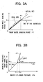
- Fig. 3A shows a phase diagram of a condition of braking force distribution among front and rear wheels, where the theoretically obtained ideal BFD line, well known in the art, (two-dot dashed line) and an actual BFD line (thin solid line ) are drawn.
- the ideal BFD line indicates a condition in which braking force is so distributed among the front and rear wheels that the front and rear wheels are simultaneously locked (Detailed of this line is described elsewhere). Thus, if a condition of braking force distribution is above this line, the possibility that a rear wheel will be locked prior to front wheels will be high.
- the actual BFD line indicates condition in which the same pressure is applied to the wheel cylinders when a vehicle runs at a certain speed. As shown, the actual BFD line linearly increases below the ideal line and intersects with the ideal line at a certain point Fc. Thus, further increase in the rear wheel braking force along the actual line would induce the locking of the rear wheel prior to the front wheels. In order to avoid this, in the embodiment, the rear wheel braking force should be held at the force of the intersecting point Fc, i.e. further increase of the rear wheel braking force is restricted.
- the force Fc corresponds to a holding pressure Pc. As seen from Fig.
- the ideal BFD line is shifted upwardly as a vehicle weight increases.
- the holding pressure is to be increased, thereby allowing the generation of larger braking force on rear wheels without exerting excessive load on the front wheels.
- the front wheel braking force is incremented for compensating for the shortage of the rear wheel braking force.
- Fig. 3B showing the braking pressures Pf, Pr in the front and rear wheel cylinders supplied with master cylinder Pm
- the increment ⁇ Pf will be determined as a function of the decrement of the rear wheel braking pressure, i.e. the difference between the master cylinder pressure and holding pressure: Pm - Pc, taking into accounts braking performances of the front and rear wheels and the vehicle speed-dependent braking effectiveness of the front wheels for the vehicle body as described in the followings.
- a braking force increment on the front wheel ⁇ Ff is equal to a force decrement on the rear wheel ⁇ Fr.
- the sectional areas and braking effective radii are determined by specifications of the front and rear wheel braking force generating apparatus, and the braking effectiveness factors are experimentally obtained.
- the calculations of expressions (2) and (3) are executed in real time with the microcomputer 92 in which all the required factors, constants and the map can be memorized to be used.
- a braking effectiveness of a rear wheel on the vehicle may be modified similarly with respect to its dependency upon a vehicle speed.
- the front wheel braking pressure is adjusted to Pm + ⁇ Pf through controlling the energization current fed to the pressure regulating valve 22 and operating the pump 42.
- BFD control for holding the rear wheels at the holding pressure Pc may be started when the master cylinder pressure Pm reaches to the holding pressure Pc on the assumption that the rear wheel braking pressure Pr is nearly equal to the master cylinder pressure in absence of BFD control and any other control for modifying braking pressure.
- a reference deceleration Gxs a positive constant
- the pressure increment for the front wheels will be calculated by regarding the master cylinder pressure Pm at the holding as the holding pressure Pc irrespective of the maps of Figs. 4A and 4B.
- BFD control lasts as long as Pm, Gx, or ⁇ Vw exceeds Pc, Gxs or ⁇ Vw.
- the BFD control may be terminated when either or all of Pm, Gx and ⁇ Vw fall below the respective reference values, Pme (a positive constant); Gxe(a positive constant); and Vwe (a positive constant).
- the reference values, Pme, Gxe, Vwe are preferably rather smaller than the corresponding Pc, Gxs, Vws, in order to avoid hunting in the control.
- ABS control When braking force on either of the wheels becomes high and renders the wheel being locked, ABS control will be executed even during BFD control. Because of BFD biased to the front wheels, a front wheel is liable to be locked so that ABS control will be normally executed for either of the front wheels. Since ABS control restricts the braking force involved therewith, thereby decreasing the total force on the vehicle, the braking pressure of the rear wheel cylinders is increased by opening the valves 28RL, RR so as to compensate for the shortage of the front wheel braking force.
- the increment for the front wheel braking pressure ⁇ Pf when ABS control for either of wheels is started, the increment for the front wheel braking pressure ⁇ Pf will be reduced.
- the increment ⁇ Pf is anticipated to be relatively high (so, a front wheel is being locked).
- instantaneous cancellation of the increment would induce an abrupt and large variation of the braking force on the front wheels, which could cause disturbance of the vehicle attitude, and therefore the process of reducing the increment is gradually or smoothly advanced.
- the braking action by the driver is not reflected in of the increment.
- a control routine shown in Fig. 6 is started by a closure of an ignition switch (not shown in Fig. 1) and cyclically repeated at a cycle time such as several milliseconds during the operation of the vehicle.
- the holding pressure Pc is calculated based upon current vehicle speed, etc. in every cycle.
- the rear wheel braking pressure is held and the variations of braking action by a driver and demand of BAC, if any, are reflected only in the front wheel braking pressure.
- steps of calculation of the holding pressure and judgment of the starting of BFD are bypassed until any condition for terminating the BFD is established.
- ABS control for either of wheels is executed, the BFD control is not started.
- step 10 the signals shown in Fig. 1B and the aforementioned parameters required in the following steps are read in. The information of presence of currently executed ABS control is also acquired.
- step 20 whether or not the BFD control has been already executed is judged. If BFD is not executed, the presence of currently executed ABS control is judged (step 22). If any of wheels is under ABS control, the process is re-started. Until ABS control is terminated, BFD control is not executed. If no ABS control is executed, a holding pressure Pc is determined in steps 30 - 50 based upon a vehicle speed V and a (the) deceleration Gx by using maps in Figs. 4A and 4B.
- steps 60 and 70 it is detected if BFD is to be executed.
- the master cylinder Pm regarded as a current rear wheel braking pressure
- the holding pressure Pc(step 60) or when the other aforementioned condition for starting BFD is established the judgment of starting of BFD is done and steps 100-120 for calculating the target front wheel braking pressure will be executed by using the aforementioned equations (2)-(3) together with the map in Fig.5.
- the holding pressure Pc is re-defined to be the value regarded as the current rear wheel braking pressure: Pc ⁇ Pm+ ⁇ Pbar, Pc ⁇ Pm(or Pwa), Pc ⁇ Pm.
- valves in the hydraulic circuit are operated in steps 130. Namely, the valves for isolating the rear wheel cylinders 28RL, RR are closed while the pressure regulating valves 22A, B and valves 60A, B are closed and opened, respectively, and the pumps 42A, B are started. Then, in order to control the front wheel braking pressure, the energization current corresponding to Pf is fed to the regulating valves 22A, B.
- Step 90 is executed directly, in which it is detected if BFD is to be terminated by checking any establishment of the aforementioned conditions for terminating BFD. If none of these conditions is established, then, step 140 for judging if ABS control for any wheel is executed. If no ABS control is executed, steps 100-130 is executed while bypassing steps 20 - 80. In step 130, the valves in the hydraulic circuit are operated so as to control only the front wheel braking pressure because the valves for holding the rear wheel cylinders has been closed in the previous cycle.
- ABS control is executed for either of the wheels, the executed BFD should be ceased as described above.
- the increment ⁇ Pf is gradually reduced by repetitively executing steps 150 - 190.
- the rear wheel braking pressure is gradually incremented since the braking force on a front wheel involved with ABS control is restricted.
- ⁇ P is set to ⁇ P2 (step 150) and ⁇ Pf is set to ⁇ Pff - ⁇ P (step 160).
- ⁇ Pff is ⁇ Pf in the previous cycle.
- ⁇ P2 may be a positive constant ( ⁇ P2 may be a value determined with the opening time of the release valves 34FL, FR.)
- step 170 the front wheel braking pressure is controlled using the decremented increment ⁇ Pf.
- step 170 When ⁇ Pf ⁇ 0 in step 170, the BFD biased to the front wheel has already disappeared and the process of the flowchart is restarted. If ABS control has been terminated during the reduction of the increment for the front wheels (step 140), steps 100 - 130 for normal BFD control are executed.
- ⁇ Pf is nearly equal to zero because, expectedly, the master cylinder pressure is almost reduced to the holding pressure Pc (see exp. (2)).
- ⁇ Pf has a significant value: the nullification of ⁇ Pf at once would cause a disturbance of the vehicle's running condition.
- the increment ⁇ Pf is gradually reduced when the terminating condition is detected.
- ⁇ P is set to ⁇ P1, which is larger than ⁇ P2 because BFD under abnormal condition should be cancelled as soon as possible.
- the increment ⁇ Pf is reduced in the following steps until ⁇ Pf ⁇ 0 in the same manner as in the case under ABS control. Together with the reduction of the increment for the front wheel, the holding of the rear wheel braking pressure is also to be released. However, there is a possibility that the front wheel braking pressure is still high enough to cause an abrupt variation in the rear wheel braking pressure. Thus, in order to avoid this, preferably, the valves 28RL, RR is opened intermittently.
- a braking system implementing the present invention may be of a type in which wheel cylinders for the respective wheels are independently controllable.
- the present invention in view of its features, is applicable to a braking system of any type.
- braking force has the identical magnitude in each of pairs of front wheels and rear wheels.
- the left and right wheels in each pair of wheels may be controlled so as to generate different forces.
- the present invention is applicable to systems where a wheel cylinder pressure sensor for each wheels is provided.
- rear wheel is held at the holding pressure by closing the corresponding valve.
- the pressure in a rear wheel cylinder may be controlled for maintaining a holding pressure through operation of the corresponding valves (pulsative or dithering increase or decrease) in lines connected toward a common line and/or a reservoir.
- the holding force and/or holding pressure for the rear wheel may be varied depending upon a vehicle speed and/or deceleration in every cycle of the control routine during BFD control.
- values for a holding pressure, Pc, Pcs or ⁇ Pc and an increment for the front wheels ⁇ Pfo, ⁇ Pf may be determined differently without deviating the scope of the present invention. Although it is preferable to take into account vehicle speed- and deceleration-dependencies and other characteristics of these values for achieving a highly accurate and appropriate control, some of those characteristics may be ignored depending upon the required accuracy of the control and/or costs of manufacturing, operating and/or maintaining a device.
Landscapes
- Engineering & Computer Science (AREA)
- Transportation (AREA)
- Mechanical Engineering (AREA)
- Physics & Mathematics (AREA)
- Fluid Mechanics (AREA)
- Microelectronics & Electronic Packaging (AREA)
- Regulating Braking Force (AREA)
- Hydraulic Control Valves For Brake Systems (AREA)
Abstract
Description
Claims (15)
- A device for controlling a braking of a vehicle having front and rear wheels, a braking system generating braking forces on the respective wheels, at least one sensor monitoring an operational condition of the vehicle including a detector detecting an amount of a braking action by a driver of the vehicle, and the device executing a braking force distribution control in which braking force on the rear wheels is lowered in comparison with braking force on the front wheels when an operational condition monitored by a sensor among the at least on sensor stratifies a predetermined condition, characterized in that braking force on the front wheels during execution of the braking force distribution control is increased, where a braking force increment on the front wheel beyond braking force corresponding to the braking action is determined based upon an increment of the braking action by the driver detected by the detector; and when anti-skid control for either of the wheels is executed, the braking force increment on the front wheel is decreased.
- A device of claim 1, characterized in that braking force on the rear wheels is increased when the anti-skid control is executed.
- A device of claim 1, characterized in that the braking force increment on the front wheel is decreased until the increment reaches to zero.
- A device of claim 1, characterized in that the decreasing of the braking force increment on the front wheel is interrupted if the anti-skid control is terminated but the increment does not reach to zero.
- A device of claim 1, wherein the braking system comprises a hydraulic circuit connected with a master cylinder and braking force generating apparatus including wheel cylinders provided for the respective wheels; and the braking action is reflected in a pressure in the master cylinder, characterized in that the decreasing of the braking force increment is executed by decreasing braking pressures in the front wheel cylinders.
- A device of claim 2, wherein the hydraulic circuit comprises a hydraulic circuit connected with a master cylinder and braking force generating apparatus including wheel cylinders provided for the respective wheels; the braking action is reflected in a pressure in the master cylinder; and valves selectively allowing fluid communication between the master cylinder and the rear wheel cylinders, characterized in that the increasing of the rear wheel braking force is executed by opening the valves.
- A device of claim 5, wherein the hydraulic circuit comprises at least a common line applying at least one of the front wheel cylinders and at least one of the rear wheel cylinders, and at least a pressure regulating valve in the common line regulating a pressure in the common line and selectively fluidly connecting the common line to master cylinder.
- A device of claim 7, wherein the hydraulic circuit is of cross dual circuit type.
- A device of claim 7, wherein the hydraulic circuit is of front-rear dual circuit type.
- A device of claim 7, wherein the hydraulic circuit comprises valves selectively allowing fluid communication between the common line and the rear wheel cylinders, characterized in that the increasing of the rear wheel braking force is executed by opening the valves.
- A device of claim 6, wherein the opening of the valves is executed intermittently.
- A device for controlling a braking of a vehicle having front and rear wheels, a braking system generating braking forces on the respective wheels, at least one sensor monitoring an operational condition of the vehicle including a detector detecting an amount of a braking action by a driver of the vehicle, the device executing a braking force distribution control in which braking force on the rear wheels is lowered in comparison with braking force on the front wheels when an operational condition monitored by a sensor among the at least one sensor stratifies a predetermined condition for starting the braking force distribution control, characterized in that braking force on the front wheels during execution of the braking force distribution control is increased during execution of the braking force distribution control, but decreased when anti-skid control for either of the wheels is executed or when an operational condition monitored by the sensor stratifies a predetermined condition for terminating the braking force distribution control.
- A device of claim 12, wherein a rate of decreasing the front wheel braking force when an operational condition monitored by a sensor among the at least one sensor stratifies a predetermined condition for terminating the braking force distribution control is faster than a rate of decreasing the front wheel braking force when anti-skid control for either of the wheels is executed.
- A device of claim 12, wherein the braking force on the front wheel is decreased until the braking force reaches to braking force requested by the braking action by the driver.
- A device of claim 12, wherein the increase of the braking force on the rear wheels is restricted during execution of the braking force distribution control but allowed when anti-skid control for either of the wheels is executed or when an operational condition monitored by a sensor among the at least one sensor stratifies a predetermined condition for terminating the braking force distribution control.
Applications Claiming Priority (2)
| Application Number | Priority Date | Filing Date | Title |
|---|---|---|---|
| JP2003103127A JP4099096B2 (en) | 2003-04-07 | 2003-04-07 | Brake control device for vehicle |
| JP2003103127 | 2003-04-07 |
Publications (2)
| Publication Number | Publication Date |
|---|---|
| EP1466799A1 true EP1466799A1 (en) | 2004-10-13 |
| EP1466799B1 EP1466799B1 (en) | 2014-05-07 |
Family
ID=32866706
Family Applications (1)
| Application Number | Title | Priority Date | Filing Date |
|---|---|---|---|
| EP04008345.3A Expired - Lifetime EP1466799B1 (en) | 2003-04-07 | 2004-04-06 | Vehicle braking control device for braking force distribution |
Country Status (3)
| Country | Link |
|---|---|
| US (1) | US8600637B2 (en) |
| EP (1) | EP1466799B1 (en) |
| JP (1) | JP4099096B2 (en) |
Cited By (2)
| Publication number | Priority date | Publication date | Assignee | Title |
|---|---|---|---|---|
| EP1967428A1 (en) * | 2006-03-10 | 2008-09-10 | Toyota Jidosha Kabushiki Kaisha | Brake controller |
| WO2009125287A1 (en) * | 2008-04-11 | 2009-10-15 | Toyota Jidosha Kabushiki Kaisha | Braking system |
Families Citing this family (8)
| Publication number | Priority date | Publication date | Assignee | Title |
|---|---|---|---|---|
| JP4508012B2 (en) * | 2005-06-30 | 2010-07-21 | 株式会社アドヴィックス | Vehicle braking control device and vehicle braking control method |
| JP5131000B2 (en) * | 2008-04-01 | 2013-01-30 | トヨタ自動車株式会社 | Brake device for vehicles with front wheel anti-skid control adapted to brake force front / rear wheel distribution control |
| US9902379B2 (en) * | 2011-05-23 | 2018-02-27 | Ford Global Technologies, Llc | Controlling wheel hop in a vehicle axle |
| DE102011118130B4 (en) | 2011-11-10 | 2013-08-01 | Knorr-Bremse Systeme für Nutzfahrzeuge GmbH | Method and device for the electronic control of the brake force distribution as a function of differential slip |
| DE102015006703A1 (en) * | 2015-05-23 | 2016-11-24 | Wabco Gmbh | Method and device for electronically controlling a vehicle deceleration as a function of differential slip between two vehicle axles |
| DE102015015922A1 (en) * | 2015-12-09 | 2017-06-14 | Wabco Gmbh | Method for adjusting brake pressures on pneumatically actuated wheel brakes of a vehicle, brake system for carrying out the method and vehicle |
| DE102017200752A1 (en) | 2016-02-26 | 2017-08-31 | Continental Teves Ag & Co. Ohg | Method for operating a brake system for motor vehicles and brake system |
| CN117162978B (en) * | 2023-08-31 | 2024-07-23 | 小米汽车科技有限公司 | Vehicle braking force control method, device, storage medium and vehicle |
Citations (5)
| Publication number | Priority date | Publication date | Assignee | Title |
|---|---|---|---|---|
| DE19518206A1 (en) | 1995-05-18 | 1996-11-21 | Bosch Gmbh Robert | ABS braking system for vehicle |
| US5826954A (en) | 1995-11-08 | 1998-10-27 | Robert Bosch Gmbh | Method and apparatus for controlling the brake system of a vehicle |
| EP1104731A2 (en) | 1999-12-03 | 2001-06-06 | WABCO GmbH & CO. OHG | Vehicle braking procedure |
| JP2001247025A (en) | 2000-03-03 | 2001-09-11 | Toyota Motor Corp | Vehicle and multi-system braking systems |
| US6474751B1 (en) | 1995-12-26 | 2002-11-05 | Denso Corporation | Hydraulic circuit having a rotary type pump and brake apparatus for a vehicle provided with the same |
Family Cites Families (15)
| Publication number | Priority date | Publication date | Assignee | Title |
|---|---|---|---|---|
| JPH05213169A (en) | 1992-02-04 | 1993-08-24 | Rhythm Corp | Hydraulic control device of brake |
| JP3497304B2 (en) | 1995-11-17 | 2004-02-16 | 本田技研工業株式会社 | Vehicle braking force control device |
| JP2000016259A (en) | 1998-07-01 | 2000-01-18 | Toyota Motor Corp | Brake control device |
| US6913326B1 (en) * | 1998-08-28 | 2005-07-05 | Toyota Jidosha Kabushiki Kaisha | Apparatus for increasing brake cylinder pressure by controlling pump motor and reducing the pressure by controlling electric energy applied to control valve |
| JP3870652B2 (en) | 2000-02-14 | 2007-01-24 | トヨタ自動車株式会社 | Brake control device for vehicle |
| DE10116353B4 (en) * | 2000-04-03 | 2006-03-30 | Aisin Seiki K.K., Kariya | Brake force distribution control device |
| DE10024848B4 (en) * | 2000-05-19 | 2010-05-20 | Lucas Varity Gmbh | Vehicle brake system with two brake circuits |
| JP4792619B2 (en) | 2000-06-15 | 2011-10-12 | トヨタ自動車株式会社 | Brake device |
| JP2002037044A (en) * | 2000-07-27 | 2002-02-06 | Aisin Seiki Co Ltd | Vehicle front / rear braking force distribution control device |
| JP3960740B2 (en) * | 2000-07-31 | 2007-08-15 | トヨタ自動車株式会社 | Brake control device for vehicle |
| US6918638B2 (en) * | 2000-08-04 | 2005-07-19 | Continental Teves Ag & Co. Ohg | Device for stabilizing a motor vehicle |
| JP2002104155A (en) * | 2000-09-29 | 2002-04-10 | Aisin Seiki Co Ltd | Vehicle motion control device |
| JP3811372B2 (en) * | 2001-05-30 | 2006-08-16 | トヨタ自動車株式会社 | Braking force control device for vehicle |
| JP4228555B2 (en) * | 2001-06-11 | 2009-02-25 | トヨタ自動車株式会社 | Brake control device for vehicle |
| JP3829925B2 (en) | 2001-11-27 | 2006-10-04 | トヨタ自動車株式会社 | Brake control device for vehicle |
-
2003
- 2003-04-07 JP JP2003103127A patent/JP4099096B2/en not_active Expired - Fee Related
-
2004
- 2004-04-02 US US10/815,765 patent/US8600637B2/en not_active Expired - Fee Related
- 2004-04-06 EP EP04008345.3A patent/EP1466799B1/en not_active Expired - Lifetime
Patent Citations (5)
| Publication number | Priority date | Publication date | Assignee | Title |
|---|---|---|---|---|
| DE19518206A1 (en) | 1995-05-18 | 1996-11-21 | Bosch Gmbh Robert | ABS braking system for vehicle |
| US5826954A (en) | 1995-11-08 | 1998-10-27 | Robert Bosch Gmbh | Method and apparatus for controlling the brake system of a vehicle |
| US6474751B1 (en) | 1995-12-26 | 2002-11-05 | Denso Corporation | Hydraulic circuit having a rotary type pump and brake apparatus for a vehicle provided with the same |
| EP1104731A2 (en) | 1999-12-03 | 2001-06-06 | WABCO GmbH & CO. OHG | Vehicle braking procedure |
| JP2001247025A (en) | 2000-03-03 | 2001-09-11 | Toyota Motor Corp | Vehicle and multi-system braking systems |
Non-Patent Citations (1)
| Title |
|---|
| PATENT ABSTRACTS OF JAPAN vol. 2000, no. 26 1 July 2002 (2002-07-01) * |
Cited By (5)
| Publication number | Priority date | Publication date | Assignee | Title |
|---|---|---|---|---|
| EP1967428A1 (en) * | 2006-03-10 | 2008-09-10 | Toyota Jidosha Kabushiki Kaisha | Brake controller |
| EP1970272A1 (en) * | 2006-03-10 | 2008-09-17 | Toyota Jidosha Kabushiki Kaisha | Brake controller |
| US7988243B2 (en) | 2006-03-10 | 2011-08-02 | Toyota Jidosha Kabushiki Kaisha | Brake controller |
| WO2009125287A1 (en) * | 2008-04-11 | 2009-10-15 | Toyota Jidosha Kabushiki Kaisha | Braking system |
| CN101998916A (en) * | 2008-04-11 | 2011-03-30 | 丰田自动车株式会社 | Braking system |
Also Published As
| Publication number | Publication date |
|---|---|
| US8600637B2 (en) | 2013-12-03 |
| JP2004306784A (en) | 2004-11-04 |
| JP4099096B2 (en) | 2008-06-11 |
| EP1466799B1 (en) | 2014-05-07 |
| US20040260446A1 (en) | 2004-12-23 |
Similar Documents
| Publication | Publication Date | Title |
|---|---|---|
| EP1466798B1 (en) | Vehicle braking control device for braking force distribution | |
| US7140699B2 (en) | Method for regulating a predetermined modifiable brake pressure | |
| US8210620B2 (en) | Braking force control system for vehicles | |
| EP0919444B1 (en) | Brake force control device | |
| JP3287259B2 (en) | Braking force control device | |
| US6572202B2 (en) | Vehicle brake control system and method therefor | |
| EP0895913B1 (en) | Braking force controller | |
| EP1466799B1 (en) | Vehicle braking control device for braking force distribution | |
| US6334655B2 (en) | Braking control apparatus for vehicles | |
| EP0895916A1 (en) | Braking force controlling device | |
| US7249807B2 (en) | Vehicle braking force control device with feedback communication between wheels | |
| JPH09136627A (en) | Vehicle braking force control device | |
| US6606548B2 (en) | Hydraulic brake pressure controller and method for pressure increase in a wheel brake cylinder | |
| JP2513184B2 (en) | Vehicle brake control device | |
| US6390568B1 (en) | Vehicle motion control system | |
| US7076357B2 (en) | Vehicle braking control device for braking force distribution | |
| US5934770A (en) | Brake control system for automotive vehicle | |
| US5620241A (en) | Hydraulic brake system with slip control | |
| US7104615B2 (en) | Vehicle motion control apparatus | |
| US5181174A (en) | Traction control method for vehicle | |
| US7246864B2 (en) | Vehicle motion control apparatus | |
| US5700069A (en) | Anti-skid control system for an automotive vehicle | |
| US5367461A (en) | Variably sensitive traction control method for vehicle | |
| JP4389296B2 (en) | Vehicle motion control device | |
| JP3275576B2 (en) | Vehicle behavior control device |
Legal Events
| Date | Code | Title | Description |
|---|---|---|---|
| PUAI | Public reference made under article 153(3) epc to a published international application that has entered the european phase |
Free format text: ORIGINAL CODE: 0009012 |
|
| AK | Designated contracting states |
Kind code of ref document: A1 Designated state(s): AT BE BG CH CY CZ DE DK EE ES FI FR GB GR HU IE IT LI LU MC NL PL PT RO SE SI SK TR |
|
| AX | Request for extension of the european patent |
Extension state: AL HR LT LV MK |
|
| 17P | Request for examination filed |
Effective date: 20040914 |
|
| AKX | Designation fees paid | ||
| RBV | Designated contracting states (corrected) |
Designated state(s): DE FR GB |
|
| REG | Reference to a national code |
Ref country code: DE Ref legal event code: 8566 |
|
| 17Q | First examination report despatched |
Effective date: 20070214 |
|
| RAP1 | Party data changed (applicant data changed or rights of an application transferred) |
Owner name: TOYOTA JIDOSHA KABUSHIKI KAISHA Owner name: ADVICS CO., LTD. |
|
| GRAP | Despatch of communication of intention to grant a patent |
Free format text: ORIGINAL CODE: EPIDOSNIGR1 |
|
| INTG | Intention to grant announced |
Effective date: 20131022 |
|
| RAP1 | Party data changed (applicant data changed or rights of an application transferred) |
Owner name: ADVICS CO., LTD. |
|
| GRAS | Grant fee paid |
Free format text: ORIGINAL CODE: EPIDOSNIGR3 |
|
| RIN1 | Information on inventor provided before grant (corrected) |
Inventor name: HAMADA, CHIAKI Inventor name: DOURA, AKIFUMI |
|
| GRAA | (expected) grant |
Free format text: ORIGINAL CODE: 0009210 |
|
| AK | Designated contracting states |
Kind code of ref document: B1 Designated state(s): DE FR GB |
|
| REG | Reference to a national code |
Ref country code: GB Ref legal event code: FG4D |
|
| REG | Reference to a national code |
Ref country code: DE Ref legal event code: R096 Ref document number: 602004045001 Country of ref document: DE Effective date: 20140618 |
|
| REG | Reference to a national code |
Ref country code: DE Ref legal event code: R097 Ref document number: 602004045001 Country of ref document: DE |
|
| PLBE | No opposition filed within time limit |
Free format text: ORIGINAL CODE: 0009261 |
|
| STAA | Information on the status of an ep patent application or granted ep patent |
Free format text: STATUS: NO OPPOSITION FILED WITHIN TIME LIMIT |
|
| 26N | No opposition filed |
Effective date: 20150210 |
|
| REG | Reference to a national code |
Ref country code: DE Ref legal event code: R084 Ref document number: 602004045001 Country of ref document: DE |
|
| REG | Reference to a national code |
Ref country code: DE Ref legal event code: R097 Ref document number: 602004045001 Country of ref document: DE Effective date: 20150210 |
|
| REG | Reference to a national code |
Ref country code: DE Ref legal event code: R084 Ref document number: 602004045001 Country of ref document: DE Effective date: 20150429 |
|
| GBPC | Gb: european patent ceased through non-payment of renewal fee |
Effective date: 20150406 |
|
| PG25 | Lapsed in a contracting state [announced via postgrant information from national office to epo] |
Ref country code: GB Free format text: LAPSE BECAUSE OF NON-PAYMENT OF DUE FEES Effective date: 20150406 |
|
| REG | Reference to a national code |
Ref country code: FR Ref legal event code: ST Effective date: 20151231 |
|
| PG25 | Lapsed in a contracting state [announced via postgrant information from national office to epo] |
Ref country code: FR Free format text: LAPSE BECAUSE OF NON-PAYMENT OF DUE FEES Effective date: 20150430 |
|
| PGFP | Annual fee paid to national office [announced via postgrant information from national office to epo] |
Ref country code: DE Payment date: 20190326 Year of fee payment: 16 |
|
| REG | Reference to a national code |
Ref country code: DE Ref legal event code: R119 Ref document number: 602004045001 Country of ref document: DE |
|
| PG25 | Lapsed in a contracting state [announced via postgrant information from national office to epo] |
Ref country code: DE Free format text: LAPSE BECAUSE OF NON-PAYMENT OF DUE FEES Effective date: 20201103 |