EP1466718A2 - Sintering using thermal image feedback - Google Patents
Sintering using thermal image feedback Download PDFInfo
- Publication number
- EP1466718A2 EP1466718A2 EP04008747A EP04008747A EP1466718A2 EP 1466718 A2 EP1466718 A2 EP 1466718A2 EP 04008747 A EP04008747 A EP 04008747A EP 04008747 A EP04008747 A EP 04008747A EP 1466718 A2 EP1466718 A2 EP 1466718A2
- Authority
- EP
- European Patent Office
- Prior art keywords
- powder
- target area
- layer
- top layer
- temperatures
- Prior art date
- Legal status (The legal status is an assumption and is not a legal conclusion. Google has not performed a legal analysis and makes no representation as to the accuracy of the status listed.)
- Granted
Links
Images


Classifications
-
- G—PHYSICS
- G05—CONTROLLING; REGULATING
- G05D—SYSTEMS FOR CONTROLLING OR REGULATING NON-ELECTRIC VARIABLES
- G05D23/00—Control of temperature
- G05D23/19—Control of temperature characterised by the use of electric means
- G05D23/27—Control of temperature characterised by the use of electric means with sensing element responsive to radiation
-
- B—PERFORMING OPERATIONS; TRANSPORTING
- B29—WORKING OF PLASTICS; WORKING OF SUBSTANCES IN A PLASTIC STATE IN GENERAL
- B29C—SHAPING OR JOINING OF PLASTICS; SHAPING OF MATERIAL IN A PLASTIC STATE, NOT OTHERWISE PROVIDED FOR; AFTER-TREATMENT OF THE SHAPED PRODUCTS, e.g. REPAIRING
- B29C64/00—Additive manufacturing, i.e. manufacturing of three-dimensional [3D] objects by additive deposition, additive agglomeration or additive layering, e.g. by 3D printing, stereolithography or selective laser sintering
- B29C64/10—Processes of additive manufacturing
- B29C64/141—Processes of additive manufacturing using only solid materials
- B29C64/153—Processes of additive manufacturing using only solid materials using layers of powder being selectively joined, e.g. by selective laser sintering or melting
-
- B—PERFORMING OPERATIONS; TRANSPORTING
- B33—ADDITIVE MANUFACTURING TECHNOLOGY
- B33Y—ADDITIVE MANUFACTURING, i.e. MANUFACTURING OF THREE-DIMENSIONAL [3-D] OBJECTS BY ADDITIVE DEPOSITION, ADDITIVE AGGLOMERATION OR ADDITIVE LAYERING, e.g. BY 3-D PRINTING, STEREOLITHOGRAPHY OR SELECTIVE LASER SINTERING
- B33Y10/00—Processes of additive manufacturing
-
- B—PERFORMING OPERATIONS; TRANSPORTING
- B33—ADDITIVE MANUFACTURING TECHNOLOGY
- B33Y—ADDITIVE MANUFACTURING, i.e. MANUFACTURING OF THREE-DIMENSIONAL [3-D] OBJECTS BY ADDITIVE DEPOSITION, ADDITIVE AGGLOMERATION OR ADDITIVE LAYERING, e.g. BY 3-D PRINTING, STEREOLITHOGRAPHY OR SELECTIVE LASER SINTERING
- B33Y30/00—Apparatus for additive manufacturing; Details thereof or accessories therefor
-
- G—PHYSICS
- G05—CONTROLLING; REGULATING
- G05D—SYSTEMS FOR CONTROLLING OR REGULATING NON-ELECTRIC VARIABLES
- G05D23/00—Control of temperature
- G05D23/19—Control of temperature characterised by the use of electric means
- G05D23/1919—Control of temperature characterised by the use of electric means characterised by the type of controller
-
- B—PERFORMING OPERATIONS; TRANSPORTING
- B29—WORKING OF PLASTICS; WORKING OF SUBSTANCES IN A PLASTIC STATE IN GENERAL
- B29C—SHAPING OR JOINING OF PLASTICS; SHAPING OF MATERIAL IN A PLASTIC STATE, NOT OTHERWISE PROVIDED FOR; AFTER-TREATMENT OF THE SHAPED PRODUCTS, e.g. REPAIRING
- B29C35/00—Heating, cooling or curing, e.g. crosslinking or vulcanising; Apparatus therefor
- B29C35/02—Heating or curing, e.g. crosslinking or vulcanizing during moulding, e.g. in a mould
- B29C35/0288—Controlling heating or curing of polymers during moulding, e.g. by measuring temperatures or properties of the polymer and regulating the process
Definitions
- This invention is in the field of freeform fabrication and is directed to the fabrication of three-dimensional objects by selective laser sintering. More specifically, it is related to temperature control in the process chamber of a laser sintering system.
- Freeform fabrication generally refers to the manufacture of articles directly from computer-aided-design (CAD) databases in an automated fashion, rather than by conventional machining of prototype articles according to engineering drawings.
- CAD computer-aided-design
- an example of a freeform fabrication technology is the selective laser sintenng process practiced in systems available from 3D Systems, Inc., in which articles are produced from a laser-fusible powder in layerwise fashion. According to this process, a thin layer of powder is dispensed and then fused, melted, or sintered, by laser energy that is directed to those portions of the powder corresponding to a cross-section of the article.
- Conventional selective laser sintering systems such as the Vanguard system available from 3D Systems, Inc., position the laser beam by way of galvanometer-driven mirrors that deflect the laser beam.
- the deflection of the laser beam is controlled, in combination with modulation of the laser itself, to direct laser energy to those locations of the fusible powder layer corresponding to the cross-section of the article to be formed in that layer.
- the computer based control system is programmed with information indicative of the desired boundaries of a plurality of cross sections of the part to be produced.
- the laser may be scanned across the powder in raster fashion, with modulation of the laser affected in combination therewith, or the laser may be directed in vector fashion.
- cross-sections of articles are formed in a powder layer by fusing powder along the outline of the cross-section in vector fashion either before or after a raster scan that "fills" the area within the vector-drawn outline.
- an additional layer of powder is then dispensed, and the process repeated, with fused portions of later layers fusing to fused portions of previous layers (as appropriate for the article), until the article is complete.
- the selective laser sintering technology has enabled the direct manufacture of three-dimensional articles of high resolution and dimensional accuracy from a variety of materials including polystyrene, some nylons, other plastics, and composite materials such as polymer coated metals and ceramics. Polystyrene parts may be used in the generation of tooling by way of the well-known "lost wax" process.
- selective laser sintering may be used for the direct fabrication of molds from a CAD database representation of the object to be molded in the fabricated molds; in this case, computer operations will "invert" the CAD database representation of the object to be formed, to directly form the negative molds from the powder.
- a laser sintering system utilizes a broad area thermal vision system, such as an infrared camera, to measure multiple temperatures across the target area and uses that temperature data as feed back to a control system.
- a broad area thermal vision system such as an infrared camera
- control system both adjusts a zoned radiant heater system and the scan speed and/or laser power to control temperatures across the target area.
- the invention includes a method for forming a three dimensional article by laser sintering comprising the steps of: dispensing a first top layer of powder on a target area; moderating the temperature of said first top layer of powder to a predetermined goal, directing an energy beam over said target area causing said first top layer of powder to fuse powder in select locations to form an integral layer; dispensing a second top layer of powder over the fused and unfused powder of said first top layer; moderating the temperature of said second top layer of powder to a predetermined goal; directing said energy beam over said target area causing said second layer of powder to form a second integral layer bonded to said first integral layer; repeating steps (a) to (f) to form additional layers that are integrally bonded to adjacent layers so as to form a three-dimensional article, wherein the temperature moderating step comprises: using a machine vision system to image multiple temperatures of the current top layer of powder and adjust those temperatures by adjusting the radiant heat output from a zoned radiant heater located above said target area.
- the invention also includes a method for forming a three dimensional article by laser sintering comprising the steps of: dispensing a first top layer of powder on a target area; moderating the temperature of the first top layer of powder to a predetermined goal; directing an energy beam over the target area causing the first top layer of powder to fuse powder in select locations to form an integral layer; dispensing a second top layer of powder over the fused and unfused powder of the first top layer; moderating the temperature of the second top layer of powder to a predetermined goal; directing the energy beam over the target area causing the second layer of powder to form a second integral layer bonded to the first integral layer; and repeating steps (a) to (f) to form additional layers that are integrally bonded to adjacent layers so as to form a three dimensional article, wherein the directing steps include the sub steps of: estimating, from known mathematical models, the desired temperatures in the region of the part being produced, then reading, from the digital output of a machine vision system the actual temperatures in the region of
- the invention also includes an apparatus for producing parts from a powder comprising: a process chamber having a target area at which an additive process is performed; a means for depositing and leveling a layer of powder on the target area; a means for fusing selected portions of a layer of the powder at the target area; a machine vision system for measuring temperatures across the x-y coordinates of the target area and a radiant heater for heating the target area to control temperatures of fused and unfused powder at top surface of the target area.
- Figure 1 illustrates, by way of background, a rendering of a conventional selective laser sintering system, indicated generally by the numeral 100 , currently sold by 3D Systems, Inc. of Valencia, California.
- Figure 1 is a rendering shown without doors for clarity.
- a carbon dioxide laser 108 and its associated scanning system 114 is shown mounted in a unit above a process chamber 102 that includes a powder bed 132 , two powder cartridge feed systems indicated generally by the numerals 124 and 126 , and a counter-rotating leveling roller 130 .
- the process chamber 102 maintains the appropriate temperature and atmospheric composition (typically an inert atmosphere such as nitrogen) for the fabrication of the article.
- an inert atmosphere such as nitrogen
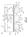
- FIG. 2 Operation of this conventional selective laser sintering system is shown in Figure 2 in a front view of the process, with no doors shown for clarity.
- a laser beam 104 is generated by laser 108 , and aimed at target area, indicated generally the numeral 110 , by way of scanning system 114, generally including laser optics and galvanometer-driven mirrors that deflect the laser beam.
- the laser and galvanometer systems are isolated from the heat of the process hot chamber 102 by a laser window 116
- the laser window 116 is situated within radiant heater elements 120 that heat the target area 110 of the powder bed 132 below. These heater elements 120 may be ring shaped (rectangular or circular) panels or radiant heater rods that surround the laser window.
- An infrared sensor or pyrometer 118 is situated at the rear of the chamber and is focused on a small area of the target surface to read and record the surface temperature. The reading from this sensor is fed into a control scheme that controls the power to the radiant heater elements 120 to maintain a constant temperature of the target surface 110 of the powder bed 132.
- the deflection of the laser beam is controlled, in combination with modulation of laser 108 itself, to direct laser energy to those locations of the fusible powder layer in the target area 110 of powder bed 132 corresponding to the cross-section of the article to be formed in that layer.
- Scanning system 114 may scan the laser beam across the powder in a raster-scan fashion, or in vector fashion.
- the two, powder cartridge feed systems feed powder into the system 100 by means of a push up piston system.
- a powder bed 132 receives powder on its horizontal part bed 131 , best seen in outline Figure 1, from the two feed pistons 125 and 127 as is described below.
- Feed system 126 first pushes up a measured amount of powder from powder 123 in system 126 by the upward movement of piston 127 and a counter-rotating roller 130 picks up and spreads the powder over the powder bed 132 in a uniform manner.
- the counter-rotating roller 130 passes completely over the target area 110 and powder bed 132 and then dumps any residual powder into an overflow container 136 .
- radiant heater elements 122 Positioned nearer the top of the process chamber 100 are radiant heater elements 122 that pre-heat the feed powder and a ring or rectangular shaped radiant heater element 120 for heating the surface of powder bed 132 in the target area 110.
- This heater element 120 has a central opening which allows laser beam 104 to pass through the optical element 116 . After a traversal of the counter-rotating roller 130 across the powder bed 132 the laser selectively fuses the layer just dispensed.
- roller 130 returns from the area of the overflow chute 136 , the feed piston 125 pushes up a prescribed amount of powder 129 in powder cartridge feed system 124 and the roller 130 dispenses powder across the powder bed 132 and the target area 110 in the opposite direction to that previously traveled and proceeds to the other overflow chute 138 to drop residual powder.
- center part bed piston 128 drops the portion of the powder bed 132 overlying its supporting part bed 131 into build chamber 106 by the desired layer thickness to make room for additional powder needed for the next layer of the article cross-section to be formed.
- the powder cartridge feed systems 124 and 126 include feed pistons 125 and 127 , controlled by motors (not shown) to move upwardly and lift (when indexed) a predetermined volume of powder into process chamber 102 .
- Part bed piston 128 is controlled by a motor (not shown) to move part bed 131 downwardly into build chamber 106 below the floor of chamber 102 by a small amount, for example 0.125 mm, to define the thickness of each layer of powder to be processed.
- Roller 130 is a counter-rotating roller that translates powder from powder cartridge feed systems 124 and 126 via feed pistons 125 and 127 onto target area 110 .
- Target area 110 refers to the top surface of heat-fusible powder (including portions previously sintered, if present) disposed above part bed 131 of Figure 1 and includes the fused and unfused powder disposed on part bed 131 which will be referred to herein with respect to Figure 3 as part powder bed 162.
- System 100 of Figure 2 also requires radiant heaters 122 over the feed pistons to pre-heat the powder to minimize any thermal shock as fresh powder is spread over the recently sintered and hot target area 110.
- This type of dual push up piston feed system with heating elements for both feed and part beds is implemented commercially in the Vanguard selective laser sintering system sold by 3D Systems, Inc. of Valencia, California.
- An alternative powder delivery system (not shown) that uses overhead hoppers can be utilized to feed powder from above and either side of powder bed 132 , in front of a delivery apparatus such as a wiper or scraper.
- An apparatus for carrying out the present invention can be seen diagrammatically in Figure 3 and is indicated generally as numeral 150 .
- a means for selectively fusing selected portions of a layer of powder is provided by a laser 154 to provide energy to selectively fuse powders having its beam directed by a scanner system 158 .
- a preferred laser is a carbon dioxide gas laser that is typically between 10 and 200 watts in power. Other lasers that provide the required energies at appropriate wavelengths can be used.
- the scanning system is typically galvanometer based but could use other approaches.
- a part powder bed 162 is heated by a zoned radiant heater system 170 .
- the zoned radiant heater system 170 can be of any shape but generally has a shape that matches the geometry of the part bed 162 and has a central open region through which the laser beam and any temperature sensors line of sight passes.
- the rectangular part bed has a rectangular arrangement of the radiant heater.
- These radiant heaters can be any number of types including, for example, quartz rods or flat panels.
- the zoned radiant heater system 170 can be configured so that the heat input to different parts of the radiant heater can be varied in either a radial or a circumferential direction.
- a machine vision system 174 is positioned to image the part powder bed 162 .
- This machine vision system 174 is preferably an infrared camera, such as those available commercially as the IRI 1002 from Irisys of Towcester, UK or the FLIR A20M model from FLIR of North Billerica, MA. However, other systems such as a standard CCD camera measuring gray scale difference could be used.
- This camera is imaging the entire part powder bed 162, including the area 178 containing the topmost fused or melted layer of the article(s) be made and provides a digital output of the actual temperatures in the region of the three-dimensional part being built or other desired areas of the part powder bed 162 .
- the image from device 174 is digitized and the part bed divided up into a part bed matrix indicated generally by the numeral 175 with an average temperature for each cell 176 of the matrix 175. These temperatures are compared to a desired set point temperature and control signals then are sent to controller 168 to adjust the zoned radiant heater to moderate the bed temperatures to minimize deviations from the set point temperatures. Any number of objective functions could be used such as for example a least squares approach - minimizing the sum of the squares of each cell's temperature deviation from set point. At the same time control signals would be sent to controller 166 to adjust the laser power based on temperature deviations from a desired set point temperature for the cells 176 associated with the fused or melted region 178 .
- This approach can be used to control the overall top layer of powder temperatures before the laser selectively fuses the next layer of powder.
- An improved level of control can then be implemented during the actual laser operation as follows.
- a historical logging of build data including parameters such as heater temperature and laser power and scanning speed is collected for the exact or similar three-dimensional parts. From this data a mathematical model is created using a custom or commercial software package for finite element thermal analysis of every cell in the part powder bed. Suitable commercial software packages that can be rewritten for use in real time for machine control include NE Nastran by Noran Engineering, Inc. of Los Alamitos, CA. and RadTherm from ThermoAnalytics, Inc. of Calumet, MI.
- an IR camera is employed in the current build to obtain the actual temperature of the top layer of powder to compare with the output of the finite element thermal analysis. Then an iterative bounding process is used to estimate the desired thermal properties of future variations of the build process from the actual temperature recordings of the IR camera compared to the mathematical model until the desired thermal properties and the variations in the build process coincide. Then that data is used to adjust the zoned radiant heater system, the energy beam power and/or the scanning speed of the laser during the laser-directing step to achieve the ideal or desired temperatures in the top layer of powder estimated from the mathematical models. The overall temperature control of this two level control process results in a dramatic improvement over historical control. Temperature control is being implemented in the layer dispensing and leveling step as well as during the laser-directing step. In this approach the mathematical model is understood to encompass the process of collecting all of the data and defining the future variations of the build process from the actual temperature recordings of the IR camera.
- This design approach improves the overall temperature control in the top layers of the part bed and acts to reduce the temperature differences, between the powder just fused and the surrounding non-fused powder, thereby reducing undesirable shrinkages that can lead to curl and distortion of fabricated articles.
- the present system affords the opportunity to adjust the energy power of the laser beam, as well as the laser scanning speed, in different areas of the powder bed to achieve temperature control over the entire powder bed and over the cross-sections of multiple parts being fabricated to obtain successful builds for all parts being fabricated with reduced and undesirable shrinkages and less resultant curl and distortion.
- zoned radiant heater system is intended to encompass multiple radiant heaters, multi-zone radiant heaters, and radiant heaters of different geometric shapes and configurations such as annular, rectangular, rod or panel. All patents and patent applications referenced herein are hereby specifically incorporated by reference in pertinent part. All modifications coming within the spirit and scope of the accompanying claims are encompassed.
Landscapes
- Engineering & Computer Science (AREA)
- Physics & Mathematics (AREA)
- Chemical & Material Sciences (AREA)
- Materials Engineering (AREA)
- Manufacturing & Machinery (AREA)
- General Physics & Mathematics (AREA)
- Automation & Control Theory (AREA)
- Optics & Photonics (AREA)
- Mechanical Engineering (AREA)
- Powder Metallurgy (AREA)
Abstract
Description
- This invention is in the field of freeform fabrication and is directed to the fabrication of three-dimensional objects by selective laser sintering. More specifically, it is related to temperature control in the process chamber of a laser sintering system.
- The field of freeform fabrication of parts has, in recent years, made significant improvements in providing high strength, high density parts for use in the design and pilot production of many useful articles. Freeform fabrication generally refers to the manufacture of articles directly from computer-aided-design (CAD) databases in an automated fashion, rather than by conventional machining of prototype articles according to engineering drawings. As a result, the time required to produce prototype parts from engineering designs has been reduced from several weeks to a matter of a few hours.
- By way of background, an example of a freeform fabrication technology is the selective laser sintenng process practiced in systems available from 3D Systems, Inc., in which articles are produced from a laser-fusible powder in layerwise fashion. According to this process, a thin layer of powder is dispensed and then fused, melted, or sintered, by laser energy that is directed to those portions of the powder corresponding to a cross-section of the article. Conventional selective laser sintering systems, such as the Vanguard system available from 3D Systems, Inc., position the laser beam by way of galvanometer-driven mirrors that deflect the laser beam. The deflection of the laser beam is controlled, in combination with modulation of the laser itself, to direct laser energy to those locations of the fusible powder layer corresponding to the cross-section of the article to be formed in that layer. The computer based control system is programmed with information indicative of the desired boundaries of a plurality of cross sections of the part to be produced. The laser may be scanned across the powder in raster fashion, with modulation of the laser affected in combination therewith, or the laser may be directed in vector fashion. In some applications, cross-sections of articles are formed in a powder layer by fusing powder along the outline of the cross-section in vector fashion either before or after a raster scan that "fills" the area within the vector-drawn outline. In any case, after the selective fusing of powder in a given layer, an additional layer of powder is then dispensed, and the process repeated, with fused portions of later layers fusing to fused portions of previous layers (as appropriate for the article), until the article is complete.
- Detailed description of the selective laser sintering technology may be found in U.S. Patent No. 4,863,538, U.S. Patent No. 5,132,143, and U.S. Patent No. 4,944,817, all assigned to Board of Regents, The University of Texas System, and in U.S. Patent No. 4,247,508, Housholder, all incorporated herein by this reference.
- The selective laser sintering technology has enabled the direct manufacture of three-dimensional articles of high resolution and dimensional accuracy from a variety of materials including polystyrene, some nylons, other plastics, and composite materials such as polymer coated metals and ceramics. Polystyrene parts may be used in the generation of tooling by way of the well-known "lost wax" process. In addition, selective laser sintering may be used for the direct fabrication of molds from a CAD database representation of the object to be molded in the fabricated molds; in this case, computer operations will "invert" the CAD database representation of the object to be formed, to directly form the negative molds from the powder.
- Current commercial laser sintering systems, such as those sold by 3D Systems, Inc. of Valencia, California, utilize dual piston cartridge feed systems with a counter-rotating roller and an infrared sensor or pyrometer to measure the thermal conditions in the process chamber and the powder bed.
- Although laser systems have proven to be very effective in delivering both powder and thermal energy in a precise and efficient way the use of a single infrared sensor focused on one point on the target surface has some known limitations. The target surface does not normally have a uniform temperature across the entire surface. Thermal gradients are possible from front to back of the process chamber and powder bed due to the presence of an observation window at the front of the system. Gradients are possible from side to side due to the presence of lower temperatures at each side of the part bed. In addition, the recently fused part in the system is hotter than the surrounding powder. Recognizing this, other investigators have proposed other approaches to temperature control in laser sintering.
- U.S. Patent Numbers 5,427,733, 5,530,221, 5,393,482, and 5,508,489, all by Benda et. al. and assigned to United Technologies address this issue with approaches based on an optics and scanning system that detects the temperature of the powder at a detection point near the sintering location and uses that information to modify the laser power and/or modify the temperature of the surrounding powder by use of a traveling defocused laser beam. In this approach and others similar to it, the control is achieved by control of the laser beam power and not by control of a radiant heater. This approach has not seen widespread commercial implementation, probably due to the required sophistication and expense of the optics system as well as issues around quality of the radiated temperature signal from the powder as different powders are employed.
- A different approach was proposed by Gibson and Ming in a paper presented at the Solid FreeForm Fabrication Symposium in 1997 and entitled "Low-Cost Machine Vision Monitoring of the SLS process". In this approach the concept described was to use a machine vision system (a CCD camera) to focus on the target surface of a laser sintering process and to measure gray scale color variation of the surface to calculate temperature and modify laser power to maintain consistent part quality. This approach resulted in a lower cost, simpler implementation, but was still based on an average temperature value measured by the camera system.
- Thus a need exists for a more complete control scheme for laser sintering; one that measures temperatures all across the target surface and makes both global (radiant heater) and local (laser) adjustments to the heat input in order to maintain uniform temperatures.
- It is an aspect of the present invention to provide a method and apparatus for fabricating objects with selective laser sintering while maintaining a more uniform temperature across the entire target surface area in the process chamber.
- It is a further aspect of the present invention to provide such a method that is reliable and with acceptable cost.
- It is a feature of the method and apparatus of the present invention that a laser sintering system utilizes a broad area thermal vision system, such as an infrared camera, to measure multiple temperatures across the target area and uses that temperature data as feed back to a control system.
- It is another feature of the present invention that the control system both adjusts a zoned radiant heater system and the scan speed and/or laser power to control temperatures across the target area.
- It is an advantage of the present invention that ideal powder layer temperatures can be estimated and used to produce three-dimensional objects with reduced distortion and curl.
- It is another advantage of the present invention that the overall temperature control in the top layers of powder in the powder bed are improved.
- The invention includes a method for forming a three dimensional article by laser sintering comprising the steps of: dispensing a first top layer of powder on a target area; moderating the temperature of said first top layer of powder to a predetermined goal, directing an energy beam over said target area causing said first top layer of powder to fuse powder in select locations to form an integral layer; dispensing a second top layer of powder over the fused and unfused powder of said first top layer; moderating the temperature of said second top layer of powder to a predetermined goal; directing said energy beam over said target area causing said second layer of powder to form a second integral layer bonded to said first integral layer; repeating steps (a) to (f) to form additional layers that are integrally bonded to adjacent layers so as to form a three-dimensional article, wherein the temperature moderating step comprises: using a machine vision system to image multiple temperatures of the current top layer of powder and adjust those temperatures by adjusting the radiant heat output from a zoned radiant heater located above said target area.
- The invention also includes a method for forming a three dimensional article by laser sintering comprising the steps of: dispensing a first top layer of powder on a target area; moderating the temperature of the first top layer of powder to a predetermined goal; directing an energy beam over the target area causing the first top layer of powder to fuse powder in select locations to form an integral layer; dispensing a second top layer of powder over the fused and unfused powder of the first top layer; moderating the temperature of the second top layer of powder to a predetermined goal; directing the energy beam over the target area causing the second layer of powder to form a second integral layer bonded to the first integral layer; and repeating steps (a) to (f) to form additional layers that are integrally bonded to adjacent layers so as to form a three dimensional article, wherein the directing steps include the sub steps of: estimating, from known mathematical models, the desired temperatures in the region of the part being produced, then reading, from the digital output of a machine vision system the actual temperatures in the region of the part being produced, and then adjusting the energy beam power and/or scan speed during the directing step based on differences between the desired and actual temperatures to achieve desired temperatures across the target area.
- The invention also includes an apparatus for producing parts from a powder comprising: a process chamber having a target area at which an additive process is performed; a means for depositing and leveling a layer of powder on the target area; a means for fusing selected portions of a layer of the powder at the target area; a machine vision system for measuring temperatures across the x-y coordinates of the target area and a radiant heater for heating the target area to control temperatures of fused and unfused powder at top surface of the target area.
- These and other aspects, features and advantages of the invention will become apparent upon consideration of the following detailed disclosure of the invention, especially when it is taken in conjunction with the accompanying drawings wherein:
- Figure 1 is a view of a prior art selective laser sintering machine;
- Figure 2 is a front view of a conventional selective laser sintering machine showing some of the mechanisms involved; and
- Figure 3 is a first view of the system of the present invention showing the use of a machine vision system.
-
- Figure 1 illustrates, by way of background, a rendering of a conventional selective laser sintering system, indicated generally by the
numeral 100, currently sold by 3D Systems, Inc. of Valencia, California. Figure 1 is a rendering shown without doors for clarity. Acarbon dioxide laser 108 and its associatedscanning system 114 is shown mounted in a unit above aprocess chamber 102 that includes apowder bed 132, two powder cartridge feed systems indicated generally by thenumerals counter-rotating leveling roller 130. Theprocess chamber 102 maintains the appropriate temperature and atmospheric composition (typically an inert atmosphere such as nitrogen) for the fabrication of the article. - Operation of this conventional selective laser sintering system is shown in Figure 2 in a front view of the process, with no doors shown for clarity. A
laser beam 104 is generated bylaser 108, and aimed at target area, indicated generally thenumeral 110, by way ofscanning system 114, generally including laser optics and galvanometer-driven mirrors that deflect the laser beam. The laser and galvanometer systems are isolated from the heat of the processhot chamber 102 by alaser window 116 Thelaser window 116 is situated withinradiant heater elements 120 that heat thetarget area 110 of thepowder bed 132 below. Theseheater elements 120 may be ring shaped (rectangular or circular) panels or radiant heater rods that surround the laser window. An infrared sensor orpyrometer 118 is situated at the rear of the chamber and is focused on a small area of the target surface to read and record the surface temperature. The reading from this sensor is fed into a control scheme that controls the power to theradiant heater elements 120 to maintain a constant temperature of thetarget surface 110 of thepowder bed 132. - The deflection of the laser beam is controlled, in combination with modulation of
laser 108 itself, to direct laser energy to those locations of the fusible powder layer in thetarget area 110 ofpowder bed 132 corresponding to the cross-section of the article to be formed in that layer.Scanning system 114 may scan the laser beam across the powder in a raster-scan fashion, or in vector fashion. - The two, powder cartridge feed systems (124,126) feed powder into the
system 100 by means of a push up piston system. Apowder bed 132 receives powder on itshorizontal part bed 131, best seen in outline Figure 1, from the twofeed pistons Feed system 126 first pushes up a measured amount of powder frompowder 123 insystem 126 by the upward movement ofpiston 127 and acounter-rotating roller 130 picks up and spreads the powder over thepowder bed 132 in a uniform manner. Thecounter-rotating roller 130 passes completely over thetarget area 110 andpowder bed 132 and then dumps any residual powder into anoverflow container 136. Positioned nearer the top of theprocess chamber 100 areradiant heater elements 122 that pre-heat the feed powder and a ring or rectangular shapedradiant heater element 120 for heating the surface ofpowder bed 132 in thetarget area 110. Thisheater element 120 has a central opening which allowslaser beam 104 to pass through theoptical element 116. After a traversal of thecounter-rotating roller 130 across thepowder bed 132 the laser selectively fuses the layer just dispensed. Then theroller 130 returns from the area of theoverflow chute 136, thefeed piston 125 pushes up a prescribed amount ofpowder 129 in powdercartridge feed system 124 and theroller 130 dispenses powder across thepowder bed 132 and thetarget area 110 in the opposite direction to that previously traveled and proceeds to theother overflow chute 138 to drop residual powder. Before theroller 130 begins each traverse of thepowder bed 132, centerpart bed piston 128 drops the portion of thepowder bed 132 overlying its supportingpart bed 131 intobuild chamber 106 by the desired layer thickness to make room for additional powder needed for the next layer of the article cross-section to be formed. - The powder
cartridge feed systems feed pistons process chamber 102.Part bed piston 128 is controlled by a motor (not shown) to movepart bed 131 downwardly intobuild chamber 106 below the floor ofchamber 102 by a small amount, for example 0.125 mm, to define the thickness of each layer of powder to be processed.Roller 130 is a counter-rotating roller that translates powder from powdercartridge feed systems feed pistons target area 110. When traveling in either direction the roller carries any residual powder not deposited on thetarget area 110 andpowder bed 132 into overflow cartridges (136,138) on either end of theprocess chamber 102.Target area 110, for purposes of the description in this disclosure, refers to the top surface of heat-fusible powder (including portions previously sintered, if present) disposed abovepart bed 131 of Figure 1 and includes the fused and unfused powder disposed onpart bed 131 which will be referred to herein with respect to Figure 3 aspart powder bed 162.System 100 of Figure 2 also requiresradiant heaters 122 over the feed pistons to pre-heat the powder to minimize any thermal shock as fresh powder is spread over the recently sintered andhot target area 110. This type of dual push up piston feed system with heating elements for both feed and part beds is implemented commercially in the Vanguard selective laser sintering system sold by 3D Systems, Inc. of Valencia, California. An alternative powder delivery system (not shown) that uses overhead hoppers can be utilized to feed powder from above and either side ofpowder bed 132, in front of a delivery apparatus such as a wiper or scraper. - An apparatus for carrying out the present invention can be seen diagrammatically in Figure 3 and is indicated generally as
numeral 150. For clarity of illustration the surrounding process chamber and machine is omitted and only the relevant mechanisms are shown. A means for selectively fusing selected portions of a layer of powder is provided by alaser 154 to provide energy to selectively fuse powders having its beam directed by ascanner system 158. A preferred laser is a carbon dioxide gas laser that is typically between 10 and 200 watts in power. Other lasers that provide the required energies at appropriate wavelengths can be used. The scanning system is typically galvanometer based but could use other approaches. Apart powder bed 162 is heated by a zonedradiant heater system 170. The zonedradiant heater system 170 can be of any shape but generally has a shape that matches the geometry of thepart bed 162 and has a central open region through which the laser beam and any temperature sensors line of sight passes. In the case illustrated in Figure 3, the rectangular part bed has a rectangular arrangement of the radiant heater. These radiant heaters can be any number of types including, for example, quartz rods or flat panels. The zonedradiant heater system 170 can be configured so that the heat input to different parts of the radiant heater can be varied in either a radial or a circumferential direction. Amachine vision system 174 is positioned to image thepart powder bed 162. Thismachine vision system 174 is preferably an infrared camera, such as those available commercially as the IRI 1002 from Irisys of Towcester, UK or the FLIR A20M model from FLIR of North Billerica, MA. However, other systems such as a standard CCD camera measuring gray scale difference could be used. This camera is imaging the entirepart powder bed 162, including thearea 178 containing the topmost fused or melted layer of the article(s) be made and provides a digital output of the actual temperatures in the region of the three-dimensional part being built or other desired areas of thepart powder bed 162. - Not shown is the means for depositing and leveling a layer of powder in the target area. A number of different approaches are possible here. One potential system is described in U.S. Patent number 5,252,264, and is practiced in commercial systems such as the aforementioned Vanguard laser sintering system. This system feeds powder from each side of the target area by means of push up powder feed systems and then levels those powders with a counter-rotating roller system. Another alternative approach is to feed powders from overhead powder bins and level with wiper blades.
- In operation the image from
device 174 is digitized and the part bed divided up into a part bed matrix indicated generally by the numeral 175 with an average temperature for eachcell 176 of thematrix 175. These temperatures are compared to a desired set point temperature and control signals then are sent tocontroller 168 to adjust the zoned radiant heater to moderate the bed temperatures to minimize deviations from the set point temperatures. Any number of objective functions could be used such as for example a least squares approach - minimizing the sum of the squares of each cell's temperature deviation from set point. At the same time control signals would be sent tocontroller 166 to adjust the laser power based on temperature deviations from a desired set point temperature for thecells 176 associated with the fused or meltedregion 178. - This approach can be used to control the overall top layer of powder temperatures before the laser selectively fuses the next layer of powder. An improved level of control can then be implemented during the actual laser operation as follows. A historical logging of build data including parameters such as heater temperature and laser power and scanning speed is collected for the exact or similar three-dimensional parts. From this data a mathematical model is created using a custom or commercial software package for finite element thermal analysis of every cell in the part powder bed. Suitable commercial software packages that can be rewritten for use in real time for machine control include NE Nastran by Noran Engineering, Inc. of Los Alamitos, CA. and RadTherm from ThermoAnalytics, Inc. of Calumet, MI. Next an IR camera is employed in the current build to obtain the actual temperature of the top layer of powder to compare with the output of the finite element thermal analysis. Then an iterative bounding process is used to estimate the desired thermal properties of future variations of the build process from the actual temperature recordings of the IR camera compared to the mathematical model until the desired thermal properties and the variations in the build process coincide. Then that data is used to adjust the zoned radiant heater system, the energy beam power and/or the scanning speed of the laser during the laser-directing step to achieve the ideal or desired temperatures in the top layer of powder estimated from the mathematical models. The overall temperature control of this two level control process results in a dramatic improvement over historical control. Temperature control is being implemented in the layer dispensing and leveling step as well as during the laser-directing step. In this approach the mathematical model is understood to encompass the process of collecting all of the data and defining the future variations of the build process from the actual temperature recordings of the IR camera.
- This design approach improves the overall temperature control in the top layers of the part bed and acts to reduce the temperature differences, between the powder just fused and the surrounding non-fused powder, thereby reducing undesirable shrinkages that can lead to curl and distortion of fabricated articles.
- Additionally, where the powder bed has multiple three-dimensional objects being fabricated in the same build, and there is non-uniformity in the powder bed temperature, the present system affords the opportunity to adjust the energy power of the laser beam, as well as the laser scanning speed, in different areas of the powder bed to achieve temperature control over the entire powder bed and over the cross-sections of multiple parts being fabricated to obtain successful builds for all parts being fabricated with reduced and undesirable shrinkages and less resultant curl and distortion.
- Having illustrated and described the principles of our invention in a preferred embodiment thereof, it should be readily apparent to those skilled in the art that the invention can be modified in arrangement and detail without departing from such principles while employing the invention in a laser sintering system. For example, it is to be understood that the zoned radiant heater system is intended to encompass multiple radiant heaters, multi-zone radiant heaters, and radiant heaters of different geometric shapes and configurations such as annular, rectangular, rod or panel. All patents and patent applications referenced herein are hereby specifically incorporated by reference in pertinent part. All modifications coming within the spirit and scope of the accompanying claims are encompassed.
Claims (13)
- A method for forming a three dimensional article by laser sintering comprising the steps of.(a) dispensing a first top layer of powder on a target area;(b) moderating the temperature of said first top layer of powder to a predetermined temperature;(c) directing an energy beam over said target area causing said first top layer of powder to fuse powder in select locations to form an integral layer;(d) dispensing a second top layer of powder over the fused and unfused powder of said first top layer;(e) moderating the temperature of said second top layer of powder to a second predetermined temperature;(f) directing said energy beam over said target area causing said second top layer of powder to form a second integral layer bonded to said first integral layer;(g) repeating steps (a) to (f) to form additional layers that are integrally bonded to adjacent layers so as to form a three dimensional article, wherein the temperature moderating steps comprise: using a machine vision system to image multiple temperatures of the current top layer of powder and adjusting those temperatures by adjusting the radiant heat output from a zoned radiant heater located above the target area.
- The method of claim 1 wherein said machine vision system is an infrared camera.
- The method of claim 2 wherein said energy beam is a carbon dioxide laser.
- A method for forming a three dimensional article by laser sintering comprising the steps of:(a) dispensing a first top layer of powder on a target area;(b) moderating the temperature of said first top layer of powder to a predetermined temperature;(c) directing an energy beam over said target area causing said first top layer of powder to fuse powder in select locations to form an integral layer;(d) dispensing a second top layer of powder over the fused and unfused powder of said first top layer;(e) moderating the temperature of said second top layer of powder to a second predetermined temperature;(f) directing said energy beam over said target area causing said second layer of powder to form a second integral layer bonded to said first integral layer;(g) repeating steps (a) to (f) to form additional layers that are integrally bonded to adjacent layers so as to form a three dimensional article, wherein the directing steps include the sub steps of:i. estimating, from known mathematical models, the desired temperatures in the region of the part being produced:ii reading, from the digital output of a machine vision system, the actual temperatures in the region of the part being produced:iii. adjusting the energy beam power and scan speed during the directing step based on differences between the desired and actual temperatures to achieve desired temperatures across said target area.
- The method of claim 4 wherein said machine vision system is an infrared camera.
- The method of claim 5 wherein said energy beam is a carbon dioxide laser.
- An apparatus for producing parts from a powder, the apparatus comprising:(a) a chamber having a target area at which an additive process is performed;(b) means for depositing and leveling a layer of powder on said target area;(c) means for fusing selected portions of a layer of the powder at said target area;(d) machine vision system for measuring temperatures across the x-y coordinates of said target area(e) radiant heater for heating said target area to control temperatures of fused and unfused powder at top surface of said target area.
- The apparatus of claim 7 wherein said machine vision system is an infrared camera.
- The apparatus of claim 8 wherein said radiant heater is a zoned radiant heater that has different zones to deliver different levels of energy to different parts of said target area.
- The apparatus of claim 9 wherein the power output of said zoned radiant heater can be varied around the circumference of said zoned radiant heater.
- The apparatus of claim 10 wherein the power output of said zoned radiant heater can be varied in a radial direction from the center of said target area.
- An apparatus for producing parts from a powder, the apparatus comprising:(a) a chamber having a target area at which an additive process is performed;(b) means for depositing and leveling a layer of powder on the target area;(c) an energy beam for fusing selected portions of a layer of the powder at the target area;(d) machine vision system for measuring temperatures across the x-y coordinates of said target area;(e) control means for adjusting said energy beam scan speed and power in response to said measured temperatures and to desired temperatures estimated from mathematical models.
- The apparatus of claim 12 wherein said machine vision system is an infrared camera.
Applications Claiming Priority (2)
| Application Number | Priority Date | Filing Date | Title |
|---|---|---|---|
| US10/410,686 US6815636B2 (en) | 2003-04-09 | 2003-04-09 | Sintering using thermal image feedback |
| US410686 | 2003-04-09 |
Publications (3)
| Publication Number | Publication Date |
|---|---|
| EP1466718A2 true EP1466718A2 (en) | 2004-10-13 |
| EP1466718A3 EP1466718A3 (en) | 2009-03-18 |
| EP1466718B1 EP1466718B1 (en) | 2011-06-15 |
Family
ID=32869212
Family Applications (1)
| Application Number | Title | Priority Date | Filing Date |
|---|---|---|---|
| EP04008747A Expired - Lifetime EP1466718B1 (en) | 2003-04-09 | 2004-04-13 | Sintering method and apparatus using thermal image feedback |
Country Status (4)
| Country | Link |
|---|---|
| US (1) | US6815636B2 (en) |
| EP (1) | EP1466718B1 (en) |
| JP (1) | JP4146385B2 (en) |
| DE (1) | DE102004017769B4 (en) |
Cited By (126)
| Publication number | Priority date | Publication date | Assignee | Title |
|---|---|---|---|---|
| WO2006105827A1 (en) * | 2005-04-06 | 2006-10-12 | Eos Gmbh Electro Optical Systems | Device and method for the production of a three-dimensional object |
| DE102004057865B4 (en) * | 2004-11-30 | 2008-01-10 | Cl Schutzrechtsverwaltungs Gmbh | Device for producing a three-dimensional object |
| DE102007056984A1 (en) | 2007-11-27 | 2009-05-28 | Eos Gmbh Electro Optical Systems | Method for producing a three-dimensional object by means of laser sintering |
| US7569174B2 (en) | 2004-12-07 | 2009-08-04 | 3D Systems, Inc. | Controlled densification of fusible powders in laser sintering |
| DE102009015282A1 (en) | 2009-04-01 | 2010-10-07 | Eos Gmbh Electro Optical Systems | Method for generative production of three-dimensional object by a device, comprises layer-wisely applying a powder material on a carrier of the device or a layer applied on the carrier, where the carrier defines a building area |
| CN103056362A (en) * | 2011-10-21 | 2013-04-24 | 普拉特及惠特尼火箭达因公司 | Real time cap flattening during heat treat |
| CN103084573A (en) * | 2011-11-04 | 2013-05-08 | 阿尔斯通技术有限公司 | Process for production of articles made of gamma-prime precipitation-strengthened nickel-base superalloy by selective laser melting (SLM) |
| EP2666612A1 (en) * | 2012-05-25 | 2013-11-27 | MTU Aero Engines GmbH | Method and device for forming at least one three-dimensional component |
| CN103485266A (en) * | 2013-10-09 | 2014-01-01 | 武汉武大卓越科技有限责任公司 | High-definition pavement image acquisition method and apparatus |
| WO2014095200A1 (en) * | 2012-12-17 | 2014-06-26 | Arcam Ab | Additive manufacturing method and apparatus |
| CN103949638A (en) * | 2014-05-09 | 2014-07-30 | 张百成 | Light-split single-light source double-scanning electron microscope type selective laser melting molding device |
| WO2014135141A1 (en) * | 2013-03-06 | 2014-09-12 | MTU Aero Engines AG | Method and device for evaluating the quality of a component produced by means of an additive laser sintering and/or laser melting method |
| WO2014143310A1 (en) * | 2013-03-15 | 2014-09-18 | Rolls-Royce Corporation | Repair of gas turbine engine components |
| FR3010785A1 (en) * | 2013-09-18 | 2015-03-20 | Snecma | METHOD FOR CONTROLLING THE ENERGY DENSITY OF A LASER BEAM BY IMAGE ANALYSIS AND CORRESPONDING DEVICE |
| US9073265B2 (en) | 2011-01-28 | 2015-07-07 | Arcam Ab | Method for production of a three-dimensional body |
| US9079248B2 (en) | 2011-12-28 | 2015-07-14 | Arcam Ab | Method and apparatus for increasing the resolution in additively manufactured three-dimensional articles |
| EP2598313B1 (en) | 2010-07-28 | 2015-08-12 | CL Schutzrechtsverwaltungs GmbH | Method and apparatus for producing a three-dimensional component |
| US9126167B2 (en) | 2012-05-11 | 2015-09-08 | Arcam Ab | Powder distribution in additive manufacturing |
| EP2942130A1 (en) * | 2014-05-09 | 2015-11-11 | MTU Aero Engines GmbH | Apparatus and method for additive manufacturing of at least a device component |
| CN105033255A (en) * | 2015-07-31 | 2015-11-11 | 南京航空航天大学 | Method for directly obtaining martensite die steel through laser 3D printing technology |
| CN105312569A (en) * | 2015-11-10 | 2016-02-10 | 西安铂力特激光成形技术有限公司 | Layered block metal material adding manufacturing method |
| US9310188B2 (en) | 2014-08-20 | 2016-04-12 | Arcam Ab | Energy beam deflection speed verification |
| CN105751516A (en) * | 2016-04-27 | 2016-07-13 | 深圳市七号科技有限公司 | 3D printer with power failure continuous printing function and printing method |
| US9399256B2 (en) | 2014-06-20 | 2016-07-26 | Velo3D, Inc. | Apparatuses, systems and methods for three-dimensional printing |
| US9399321B2 (en) | 2009-07-15 | 2016-07-26 | Arcam Ab | Method and apparatus for producing three-dimensional objects |
| US9406483B1 (en) | 2015-01-21 | 2016-08-02 | Arcam Ab | Method and device for characterizing an electron beam using an X-ray detector with a patterned aperture resolver and patterned aperture modulator |
| WO2016123549A1 (en) * | 2015-01-29 | 2016-08-04 | Alcoa Inc. | Systems and methods for modelling additively manufactured bodies |
| WO2016119889A1 (en) * | 2015-01-30 | 2016-08-04 | Hewlett-Packard Development Company, L.P. | Fabricating three dimensional objects |
| US9415443B2 (en) | 2013-05-23 | 2016-08-16 | Arcam Ab | Method and apparatus for additive manufacturing |
| CN105916665A (en) * | 2014-01-16 | 2016-08-31 | 惠普发展公司,有限责任合伙企业 | Generating three-dimensional objects |
| CN105946227A (en) * | 2016-04-27 | 2016-09-21 | 深圳市七号科技有限公司 | 3D printer having fixed layer continuous printing function and printing method thereof |
| US9468973B2 (en) | 2013-06-28 | 2016-10-18 | Arcam Ab | Method and apparatus for additive manufacturing |
| EP3095591A1 (en) * | 2015-05-19 | 2016-11-23 | MTU Aero Engines GmbH | Method and device for detecting at least sections of a contour of a layer of an object obtainable by additive processing |
| US9505172B2 (en) | 2012-12-17 | 2016-11-29 | Arcam Ab | Method and apparatus for additive manufacturing |
| US9505057B2 (en) | 2013-09-06 | 2016-11-29 | Arcam Ab | Powder distribution in additive manufacturing of three-dimensional articles |
| WO2016201390A1 (en) * | 2015-06-12 | 2016-12-15 | Materialise N.V. | System and method for ensuring consistency in additive manufacturing using thermal imaging |
| US9550207B2 (en) | 2013-04-18 | 2017-01-24 | Arcam Ab | Method and apparatus for additive manufacturing |
| US9561542B2 (en) | 2012-11-06 | 2017-02-07 | Arcam Ab | Powder pre-processing for additive manufacturing |
| US9662840B1 (en) | 2015-11-06 | 2017-05-30 | Velo3D, Inc. | Adept three-dimensional printing |
| CN106794605A (en) * | 2014-10-03 | 2017-05-31 | 惠普发展公司有限责任合伙企业 | The heating of control surface |
| US9676031B2 (en) | 2013-04-23 | 2017-06-13 | Arcam Ab | Method and apparatus for forming a three-dimensional article |
| US9676033B2 (en) | 2013-09-20 | 2017-06-13 | Arcam Ab | Method for additive manufacturing |
| CN106843321A (en) * | 2016-12-30 | 2017-06-13 | 青岛卓思三维智造技术有限公司 | Temperature control system and method |
| WO2017138915A1 (en) * | 2016-02-08 | 2017-08-17 | Hewlett-Packard Development Company, L.P. | Build layer temperature control |
| CN107206683A (en) * | 2015-01-28 | 2017-09-26 | 惠普发展公司有限责任合伙企业 | Print dead band identification |
| US9782933B2 (en) | 2008-01-03 | 2017-10-10 | Arcam Ab | Method and apparatus for producing three-dimensional objects |
| US9789541B2 (en) | 2014-03-07 | 2017-10-17 | Arcam Ab | Method for additive manufacturing of three-dimensional articles |
| US9789563B2 (en) | 2013-12-20 | 2017-10-17 | Arcam Ab | Method for additive manufacturing |
| CN107297897A (en) * | 2017-06-27 | 2017-10-27 | 湖南华曙高科技有限责任公司 | The equipment and temperature field adjusting method of a kind of Layered manufacturing three-dimensional body |
| US9802253B2 (en) | 2013-12-16 | 2017-10-31 | Arcam Ab | Additive manufacturing of three-dimensional articles |
| EP3243583A1 (en) * | 2016-05-13 | 2017-11-15 | SLM Solutions Group AG | Apparatus and method for associating a position in a construction data set with a position in a building section of the apparatus |
| US20170334138A1 (en) * | 2015-01-28 | 2017-11-23 | Hewlett-Packard Development Company, L.P. | Determining heater malfunction |
| CN107438488A (en) * | 2015-03-30 | 2017-12-05 | 瑞尼斯豪公司 | Additive Manufacturing Apparatus and Methods |
| CN107530976A (en) * | 2015-07-22 | 2018-01-02 | 惠普发展公司有限责任合伙企业 | Thermal control system and its method |
| US9919360B2 (en) | 2016-02-18 | 2018-03-20 | Velo3D, Inc. | Accurate three-dimensional printing |
| US9950367B2 (en) | 2014-04-02 | 2018-04-24 | Arcam Ab | Apparatus, method, and computer program product for fusing a workpiece |
| US9962767B2 (en) | 2015-12-10 | 2018-05-08 | Velo3D, Inc. | Apparatuses for three-dimensional printing |
| US20180126649A1 (en) | 2016-11-07 | 2018-05-10 | Velo3D, Inc. | Gas flow in three-dimensional printing |
| CN108057888A (en) * | 2017-12-15 | 2018-05-22 | 佛山租我科技有限公司 | Connection rod of automobile engine laser 3D printing technique |
| WO2018125630A1 (en) * | 2016-12-29 | 2018-07-05 | 3D Systems, Inc. | Powder-based additive manufacturing temperature control by spatial light modulation |
| EP3221076A4 (en) * | 2014-11-18 | 2018-07-18 | Sigma Labs, Inc. | Multi-sensor quality inference and control for additive manufacturing processes |
| GB2531625B (en) * | 2014-06-20 | 2018-07-25 | Velo3D Inc | Apparatuses, systems and methods for three-dimensional printing |
| CN106061713B (en) * | 2014-01-16 | 2018-08-24 | 惠普发展公司,有限责任合伙企业 | Generate 3D objects |
| WO2018172855A1 (en) * | 2017-03-22 | 2018-09-27 | Kugra Sp . Z O.O. | Method and apparatus for forming a three-dimensional article by fusion of a powdered medium in a powder bed |
| US10130993B2 (en) | 2013-12-18 | 2018-11-20 | Arcam Ab | Additive manufacturing of three-dimensional articles |
| US10144063B2 (en) | 2011-12-28 | 2018-12-04 | Arcam Ab | Method and apparatus for detecting defects in freeform fabrication |
| US10144176B1 (en) | 2018-01-15 | 2018-12-04 | Velo3D, Inc. | Three-dimensional printing systems and methods of their use |
| EP3417962A1 (en) * | 2017-06-22 | 2018-12-26 | Hamilton Sundstrand Corporation | Determining the uniformity of powder layer distribution across the build plate during a powder bed fusion process |
| US10189086B2 (en) | 2011-12-28 | 2019-01-29 | Arcam Ab | Method and apparatus for manufacturing porous three-dimensional articles |
| US10207489B2 (en) | 2015-09-30 | 2019-02-19 | Sigma Labs, Inc. | Systems and methods for additive manufacturing operations |
| WO2019034394A1 (en) * | 2017-08-17 | 2019-02-21 | Eos Gmbh Electro Optical Systems | METHOD AND DEVICE FOR ADDITIVELY PRODUCING AT LEAST ONE COMPONENT LAYER OF A COMPONENT AND STORAGE MEDIUM |
| CN109365807A (en) * | 2018-10-31 | 2019-02-22 | 西安铂力特增材技术股份有限公司 | Multi-laser one-way variable speed motion control system, control method and speed control method |
| CN109365808A (en) * | 2018-10-31 | 2019-02-22 | 西安铂力特增材技术股份有限公司 | Multi-laser unidirectional powder spreading control system, control method and speed control method |
| CN109590466A (en) * | 2018-10-31 | 2019-04-09 | 西安铂力特增材技术股份有限公司 | More laser high efficiency two-way powder laying control systems and its control method |
| US10252336B2 (en) | 2016-06-29 | 2019-04-09 | Velo3D, Inc. | Three-dimensional printing and three-dimensional printers |
| US10272525B1 (en) | 2017-12-27 | 2019-04-30 | Velo3D, Inc. | Three-dimensional printing systems and methods of their use |
| WO2019092415A1 (en) * | 2017-11-10 | 2019-05-16 | Renishaw Plc | Spatial mapping of sensor data collected during additive manufacturing |
| CN109773186A (en) * | 2019-01-30 | 2019-05-21 | 湖南华曙高科技有限责任公司 | For manufacturing the increasing material manufacturing method and its equipment, readable storage medium storing program for executing of three-dimension object |
| KR20190061017A (en) * | 2016-09-27 | 2019-06-04 | 머티어리얼리스 엔브이 | Energy density mapping in a stacked manufacturing environment |
| US10315252B2 (en) | 2017-03-02 | 2019-06-11 | Velo3D, Inc. | Three-dimensional printing of three-dimensional objects |
| WO2019120847A1 (en) * | 2017-12-18 | 2019-06-27 | Siemens Aktiengesellschaft | Method and device for the additive production of a component and component |
| US10434572B2 (en) | 2013-12-19 | 2019-10-08 | Arcam Ab | Method for additive manufacturing |
| US10449696B2 (en) | 2017-03-28 | 2019-10-22 | Velo3D, Inc. | Material manipulation in three-dimensional printing |
| US10525547B2 (en) | 2016-06-01 | 2020-01-07 | Arcam Ab | Additive manufacturing of three-dimensional articles |
| US10529070B2 (en) | 2017-11-10 | 2020-01-07 | Arcam Ab | Method and apparatus for detecting electron beam source filament wear |
| US10525531B2 (en) | 2015-11-17 | 2020-01-07 | Arcam Ab | Additive manufacturing of three-dimensional articles |
| US10549348B2 (en) | 2016-05-24 | 2020-02-04 | Arcam Ab | Method for additive manufacturing |
| CN110757805A (en) * | 2019-09-25 | 2020-02-07 | 西安电子科技大学 | A kind of conductive pattern printing multi-sensor non-contact topography detection system and method |
| US10583483B2 (en) | 2015-10-15 | 2020-03-10 | Arcam Ab | Method and apparatus for producing a three-dimensional article |
| US10611092B2 (en) | 2017-01-05 | 2020-04-07 | Velo3D, Inc. | Optics in three-dimensional printing |
| US10610930B2 (en) | 2015-11-18 | 2020-04-07 | Arcam Ab | Additive manufacturing of three-dimensional articles |
| US10786865B2 (en) | 2014-12-15 | 2020-09-29 | Arcam Ab | Method for additive manufacturing |
| US10786948B2 (en) | 2014-11-18 | 2020-09-29 | Sigma Labs, Inc. | Multi-sensor quality inference and control for additive manufacturing processes |
| US10792757B2 (en) | 2016-10-25 | 2020-10-06 | Arcam Ab | Method and apparatus for additive manufacturing |
| US10800101B2 (en) | 2018-02-27 | 2020-10-13 | Arcam Ab | Compact build tank for an additive manufacturing apparatus |
| US10799975B2 (en) | 2016-02-29 | 2020-10-13 | Rolls-Royce Corporation | Directed energy deposition for processing gas turbine engine components |
| US10807187B2 (en) | 2015-09-24 | 2020-10-20 | Arcam Ab | X-ray calibration standard object |
| US10821721B2 (en) | 2017-11-27 | 2020-11-03 | Arcam Ab | Method for analysing a build layer |
| CN112126772A (en) * | 2020-02-17 | 2020-12-25 | 中冶长天国际工程有限责任公司 | An iron-containing mixture for 3D printing sintering and its preparation method and use |
| US10913217B2 (en) | 2015-06-24 | 2021-02-09 | Airbus Operations Gmbh | Method and device for series production of components made of a fiber-reinforced composite material |
| US10987752B2 (en) | 2016-12-21 | 2021-04-27 | Arcam Ab | Additive manufacturing of three-dimensional articles |
| US11014161B2 (en) | 2015-04-21 | 2021-05-25 | Arcam Ab | Method for additive manufacturing |
| US11059123B2 (en) | 2017-04-28 | 2021-07-13 | Arcam Ab | Additive manufacturing of three-dimensional articles |
| US11072117B2 (en) | 2017-11-27 | 2021-07-27 | Arcam Ab | Platform device |
| US11123799B2 (en) | 2013-06-11 | 2021-09-21 | Renishaw Plc | Additive manufacturing apparatus and method |
| EP3759762A4 (en) * | 2018-02-26 | 2021-11-10 | Formlabs, Inc. | Heating techniques in additive fabrication and related systems and methods |
| US11185926B2 (en) | 2017-09-29 | 2021-11-30 | Arcam Ab | Method and apparatus for additive manufacturing |
| US20220032553A1 (en) * | 2020-07-29 | 2022-02-03 | Seiko Epson Corporation | Three-dimensional shaping device, method for manufacturing three-dimensional shaped object, and information processing device |
| US11247274B2 (en) | 2016-03-11 | 2022-02-15 | Arcam Ab | Method and apparatus for forming a three-dimensional article |
| US11267051B2 (en) | 2018-02-27 | 2022-03-08 | Arcam Ab | Build tank for an additive manufacturing apparatus |
| US11267047B2 (en) | 2015-01-13 | 2022-03-08 | Sigma Labs, Inc. | Material qualification system and methodology |
| US11292062B2 (en) | 2017-05-30 | 2022-04-05 | Arcam Ab | Method and device for producing three-dimensional objects |
| US11325191B2 (en) | 2016-05-24 | 2022-05-10 | Arcam Ab | Method for additive manufacturing |
| US11400519B2 (en) | 2018-03-29 | 2022-08-02 | Arcam Ab | Method and device for distributing powder material |
| US11478856B2 (en) | 2013-06-10 | 2022-10-25 | Renishaw Plc | Selective laser solidification apparatus and method |
| US11517975B2 (en) | 2017-12-22 | 2022-12-06 | Arcam Ab | Enhanced electron beam generation |
| US11607875B2 (en) | 2014-08-22 | 2023-03-21 | Sigma Additive Solutions, Inc. | Method and system for monitoring additive manufacturing processes |
| US11618217B2 (en) | 2014-01-16 | 2023-04-04 | Hewlett-Packard Development Company, L.P. | Generating three-dimensional objects |
| US11629412B2 (en) | 2020-12-16 | 2023-04-18 | Rolls-Royce Corporation | Cold spray deposited masking layer |
| US20230145246A1 (en) * | 2021-11-08 | 2023-05-11 | Research & Business Foundation Sungkyunkwan University | Stack visualization method, apparatus, and computer-readable recording medium storing instructions to perform stack visualization method |
| US11679560B2 (en) | 2014-01-16 | 2023-06-20 | Hewlett-Packard Development Company, L.P. | Generating a three-dimensional object |
| US11691343B2 (en) | 2016-06-29 | 2023-07-04 | Velo3D, Inc. | Three-dimensional printing and three-dimensional printers |
| US11980938B2 (en) | 2020-11-24 | 2024-05-14 | Rolls-Royce Corporation | Bladed disk repair process with shield |
| US11999110B2 (en) | 2019-07-26 | 2024-06-04 | Velo3D, Inc. | Quality assurance in formation of three-dimensional objects |
| US12070907B2 (en) | 2016-09-30 | 2024-08-27 | Velo3D | Three-dimensional objects and their formation |
| US12350754B2 (en) | 2017-12-22 | 2025-07-08 | Arcam Ab | Electron beam source and the use of the same |
Families Citing this family (179)
| Publication number | Priority date | Publication date | Assignee | Title |
|---|---|---|---|---|
| SE524432C2 (en) * | 2002-12-19 | 2004-08-10 | Arcam Ab | Apparatus and method for making a three-dimensional product |
| SE524439C2 (en) † | 2002-12-19 | 2004-08-10 | Arcam Ab | Apparatus and method for making a three-dimensional product |
| US20100174392A1 (en) * | 2003-06-10 | 2010-07-08 | Fink Jeffrey E | Optimal dimensional and mechanical properties of laser sintered hardware by thermal analysis and parameter optimization |
| US20040254665A1 (en) * | 2003-06-10 | 2004-12-16 | Fink Jeffrey E. | Optimal dimensional and mechanical properties of laser sintered hardware by thermal analysis and parameter optimization |
| US20050242473A1 (en) * | 2004-04-28 | 2005-11-03 | 3D Systems, Inc. | Uniform thermal distribution imaging |
| US20050263934A1 (en) * | 2004-05-28 | 2005-12-01 | 3D Systems, Inc. | Single side feed parked powder wave heating with wave flattener |
| US20050263933A1 (en) * | 2004-05-28 | 2005-12-01 | 3D Systems, Inc. | Single side bi-directional feed for laser sintering |
| US7034246B2 (en) * | 2004-08-10 | 2006-04-25 | The Boeing Company | Selective laser sintering reduced volume feed mechanism |
| US6930278B1 (en) * | 2004-08-13 | 2005-08-16 | 3D Systems, Inc. | Continuous calibration of a non-contact thermal sensor for laser sintering |
| DE102004052323B4 (en) * | 2004-10-27 | 2008-01-24 | Fraunhofer-Gesellschaft zur Förderung der angewandten Forschung e.V. | Method for separating materials with a laser beam |
| US20060214335A1 (en) * | 2005-03-09 | 2006-09-28 | 3D Systems, Inc. | Laser sintering powder recycle system |
| US7807947B2 (en) * | 2005-05-09 | 2010-10-05 | 3D Systems, Inc. | Laser sintering process chamber gas curtain window cleansing in a laser sintering system |
| US7676298B2 (en) * | 2005-06-08 | 2010-03-09 | Crc For Advanced Composite Structures Limited | Method and apparatus for surface shaping of polymer composite components |
| DE102005030067A1 (en) * | 2005-06-27 | 2006-12-28 | FHS Hochschule für Technik, Wirtschaft und soziale Arbeit St. Gallen | Apparatus for producing objects using generative method, e.g. selective laser sintering, has system for generating mist of fluid between electromagnetic component and process chamber |
| DE102005059095A1 (en) * | 2005-12-10 | 2007-06-14 | Bayerische Motoren Werke Ag | Method and device for controlling the surface activation of a plastic component |
| US7317970B2 (en) * | 2006-03-02 | 2008-01-08 | Siemens Building Technologies, Inc. | Remote sensing for building automation |
| ATE466720T1 (en) * | 2006-06-20 | 2010-05-15 | Univ Leuven Kath | METHOD AND DEVICE FOR IN-SITU MONITORING AND FEEDBACK CONTROL OF SELECTIVE LASER POWDER PROCESSING |
| GB0622232D0 (en) * | 2006-11-08 | 2006-12-20 | Rumsby Philip T | Method and apparatus for laser beam alignment for solar panel scribing |
| WO2008103985A2 (en) * | 2007-02-23 | 2008-08-28 | The Exone Company, Llc | Replaceable build box for three dimensional printer |
| US7718933B2 (en) * | 2007-04-20 | 2010-05-18 | The Boeing Company | Methods and systems for direct manufacturing temperature control |
| US7515986B2 (en) * | 2007-04-20 | 2009-04-07 | The Boeing Company | Methods and systems for controlling and adjusting heat distribution over a part bed |
| GB0816308D0 (en) | 2008-09-05 | 2008-10-15 | Mtt Technologies Ltd | Optical module |
| DE102009010025B4 (en) | 2009-02-21 | 2011-06-22 | MTU Aero Engines GmbH, 80995 | A method of manufacturing an integrally bladed rotor |
| GB0917936D0 (en) | 2009-10-13 | 2009-11-25 | 3D Printer Aps | Three-dimensional printer |
| US8728388B2 (en) * | 2009-12-04 | 2014-05-20 | Honeywell International Inc. | Method of fabricating turbine components for engines |
| DE202010005162U1 (en) * | 2010-04-17 | 2010-11-04 | Evonik Degussa Gmbh | Device for reducing the lower installation space of a laser sintering system |
| DE102011009624A1 (en) * | 2011-01-28 | 2012-08-02 | Mtu Aero Engines Gmbh | Method and device for process monitoring |
| US8691333B2 (en) | 2011-06-28 | 2014-04-08 | Honeywell International Inc. | Methods for manufacturing engine components with structural bridge devices |
| US8488994B2 (en) | 2011-09-23 | 2013-07-16 | Stratasys, Inc. | Electrophotography-based additive manufacturing system with transfer-medium service loops |
| US8879957B2 (en) | 2011-09-23 | 2014-11-04 | Stratasys, Inc. | Electrophotography-based additive manufacturing system with reciprocating operation |
| CN203811991U (en) | 2011-09-23 | 2014-09-03 | 斯特拉塔西斯公司 | Additive manufacturing system for printing three-dimensional parts |
| US20130186558A1 (en) | 2011-09-23 | 2013-07-25 | Stratasys, Inc. | Layer transfusion with heat capacitor belt for additive manufacturing |
| US8568021B2 (en) | 2011-09-29 | 2013-10-29 | Schwank Ltd. | Apparatus and method for measuring heat flux from radiant heater |
| US9080777B2 (en) | 2012-01-31 | 2015-07-14 | Schwank, Ltd. | Reflector for radiant tube heater |
| US9308690B2 (en) | 2012-07-31 | 2016-04-12 | Makerbot Industries, Llc | Fabrication of objects with enhanced structural characteristics |
| DK177499B1 (en) * | 2012-09-26 | 2013-07-29 | Othonia Curing Technology Aps | COMPUTER-CONTROLLED UV-LED Curing Apparatus |
| JP6342912B2 (en) * | 2012-11-08 | 2018-06-13 | ディーディーエム システムズ, インコーポレイテッド | Additive manufacturing and repair of metal components |
| FR3002768B1 (en) * | 2013-03-01 | 2015-02-20 | Saint Gobain | PROCESS FOR THERMALLY TREATING A COATING |
| DE102013003937A1 (en) | 2013-03-08 | 2014-09-11 | Cl Schutzrechtsverwaltungs Gmbh | Method for assessing the structural quality of three-dimensional components |
| CA2900297A1 (en) * | 2013-03-15 | 2014-09-18 | Matterfab Corp. | Cartridge for an additive manufacturing apparatus and method |
| US20140271326A1 (en) | 2013-03-15 | 2014-09-18 | 3D Systems, Inc. | Powder Distribution for Laser Sintering Systems |
| DE102013208651A1 (en) * | 2013-05-10 | 2014-11-13 | Eos Gmbh Electro Optical Systems | A method of automatically calibrating a device for generatively producing a three-dimensional object |
| US9023566B2 (en) | 2013-07-17 | 2015-05-05 | Stratasys, Inc. | ABS part material for electrophotography-based additive manufacturing |
| US9144940B2 (en) | 2013-07-17 | 2015-09-29 | Stratasys, Inc. | Method for printing 3D parts and support structures with electrophotography-based additive manufacturing |
| US9029058B2 (en) | 2013-07-17 | 2015-05-12 | Stratasys, Inc. | Soluble support material for electrophotography-based additive manufacturing |
| FR3010334B1 (en) * | 2013-09-09 | 2015-09-25 | Michelin & Cie | POWDER BED DEPOSITION DEVICE ON SURFACE PROVIDED WITH AN ELECTROMAGNETIC RESPONSE PROBE, AND CORRESPONDING METHOD |
| GB201316815D0 (en) * | 2013-09-23 | 2013-11-06 | Renishaw Plc | Additive manufacturing apparatus and method |
| US20220362857A1 (en) * | 2013-10-18 | 2022-11-17 | +Mfg, LLC | Method and apparatus for fabrication of articles by molten and semi-molten deposition |
| DE102013017792A1 (en) | 2013-10-28 | 2015-04-30 | Cl Schutzrechtsverwaltungs Gmbh | Method for producing a three-dimensional component |
| DE102013224649B4 (en) * | 2013-11-29 | 2024-05-23 | Dmg Mori Ultrasonic Lasertec Gmbh | Machine tool |
| US20150165693A1 (en) * | 2013-12-17 | 2015-06-18 | Kabir Sagoo | Systems and Methods for Rapid Qualification of Products Created by Additive Manufacturing Processes with Doped Materials |
| CN105899346B (en) * | 2014-01-16 | 2017-11-07 | 惠普发展公司,有限责任合伙企业 | Three-dimensional (3D) printing method |
| CN105934332B (en) * | 2014-01-16 | 2018-06-26 | 惠普发展公司,有限责任合伙企业 | Generate 3D objects |
| EP3094669B1 (en) | 2014-01-16 | 2022-11-23 | Hewlett-Packard Development Company, L.P. | Polymeric powder composition for three-dimensional (3d) printing |
| WO2015108560A1 (en) * | 2014-01-16 | 2015-07-23 | Hewlett-Packard Development Company, L.P. | Temperature determination based on emissivity |
| DE112014006179T5 (en) | 2014-01-16 | 2016-11-17 | Hewlett-Packard Development Company, L.P. | Create three-dimensional objects |
| US10252474B2 (en) | 2014-01-16 | 2019-04-09 | Hewlett-Packard Development Company, L.P. | Temperature determination based on emissivity |
| US20160375676A1 (en) * | 2014-01-24 | 2016-12-29 | Verrana, Llc | Use of 3D printing for anticounterfeiting |
| US9770869B2 (en) | 2014-03-18 | 2017-09-26 | Stratasys, Inc. | Additive manufacturing with virtual planarization control |
| US10011071B2 (en) | 2014-03-18 | 2018-07-03 | Evolve Additive Solutions, Inc. | Additive manufacturing using density feedback control |
| US9868255B2 (en) | 2014-03-18 | 2018-01-16 | Stratasys, Inc. | Electrophotography-based additive manufacturing with pre-sintering |
| US9643357B2 (en) | 2014-03-18 | 2017-05-09 | Stratasys, Inc. | Electrophotography-based additive manufacturing with powder density detection and utilization |
| US10144175B2 (en) | 2014-03-18 | 2018-12-04 | Evolve Additive Solutions, Inc. | Electrophotography-based additive manufacturing with solvent-assisted planarization |
| US9919479B2 (en) | 2014-04-01 | 2018-03-20 | Stratasys, Inc. | Registration and overlay error correction of electrophotographically formed elements in an additive manufacturing system |
| US9688027B2 (en) | 2014-04-01 | 2017-06-27 | Stratasys, Inc. | Electrophotography-based additive manufacturing with overlay control |
| CN103978307B (en) * | 2014-04-30 | 2015-08-05 | 中国科学院化学研究所 | A kind of macromolecular material Ultra-Violet Laser 3D Method of printing for accurate temperature controlling and device |
| CN104029395B (en) * | 2014-05-31 | 2016-01-06 | 大连理工大学 | The method of laser power is determined fast in the clean forming process of a kind of Laser Near |
| KR101665939B1 (en) * | 2014-07-18 | 2016-10-25 | 한국생산기술연구원 | A material supply apparatus for 3D manufacturing, a rapid 3D printer therewith, and 3D manufacturing method using it. |
| WO2016026706A1 (en) | 2014-08-20 | 2016-02-25 | Etxe-Tar, S.A. | Method and system for additive manufacturing using a light beam |
| DE102014216567A1 (en) | 2014-08-21 | 2016-02-25 | MTU Aero Engines AG | Method for determining the quality of an additively manufactured component |
| CN106715036B (en) * | 2014-08-26 | 2019-12-10 | 密执安州立大学董事会 | Apparatus and method for direct writing of single crystal superalloys and metals |
| DE102014112446A1 (en) | 2014-08-29 | 2016-03-03 | Exone Gmbh | Method and device for unpacking a component |
| DE102014112447B4 (en) | 2014-08-29 | 2025-04-24 | Exone Gmbh | 3D printer, 3D printer arrangement and generative manufacturing process |
| CN104259458B (en) * | 2014-09-29 | 2017-01-18 | 湖南华曙高科技有限责任公司 | Rapid prototyping device for three-dimensional object manufacture and heating device thereof |
| US10723115B2 (en) | 2014-09-30 | 2020-07-28 | Hewlett-Packard Development Company, L.P. | Cooling times for three-dimensional objects |
| US10112262B2 (en) | 2014-10-28 | 2018-10-30 | General Electric Company | System and methods for real-time enhancement of build parameters of a component |
| CN104353833A (en) * | 2014-11-07 | 2015-02-18 | 中国石油大学(华东) | 3D (3-dimnesional) printing manufacturing method for PDC (primary domain controller) drill bit body |
| US10668532B2 (en) * | 2015-02-12 | 2020-06-02 | Raytheon Technologies Corporation | Additively manufactured non-contact support |
| US10589466B2 (en) * | 2015-02-28 | 2020-03-17 | Xerox Corporation | Systems and methods for implementing multi-layer addressable curing of ultraviolet (UV) light curable inks for three dimensional (3D) printed parts and components |
| DE102015103127A1 (en) * | 2015-03-04 | 2016-09-08 | Trumpf Laser- Und Systemtechnik Gmbh | Irradiation system for a device for additive manufacturing |
| DE102015204800B3 (en) | 2015-03-17 | 2016-12-01 | MTU Aero Engines AG | Method and device for quality evaluation of a component produced by means of an additive manufacturing method |
| EP3082102A1 (en) | 2015-04-13 | 2016-10-19 | MTU Aero Engines GmbH | Method of evaluating at least one component layer produced by means of a generative powder layer |
| RU2602329C2 (en) * | 2015-04-13 | 2016-11-20 | Общество с ограниченной ответственностью Научно-производственный центр "Лазеры и аппаратура ТМ" | Device for production of 3d articles |
| WO2016195665A1 (en) * | 2015-06-02 | 2016-12-08 | Hewlett-Packard Development Company, L.P. | Sacrificial objects based on a temperature threshold |
| CN107548349A (en) * | 2015-06-10 | 2018-01-05 | 惠普发展公司有限责任合伙企业 | Build temperature modulation |
| CN107530961B (en) | 2015-07-21 | 2020-02-18 | 惠普发展公司有限责任合伙企业 | Object Generates Temperature Measurements |
| BR112017023040A2 (en) | 2015-07-30 | 2018-07-03 | Hewlett Packard Development Co | controlled heating for 3d printing. |
| EP3261821B1 (en) | 2015-07-30 | 2022-10-05 | Hewlett-Packard Development Company, L.P. | Color calibration for three-dimensional printing |
| EP3271154A4 (en) * | 2015-08-20 | 2018-12-05 | Hewlett-Packard Development Company, L.P. | Filtering temperature distribution data of build material |
| US10500675B2 (en) * | 2015-11-02 | 2019-12-10 | General Electric Company | Additive manufacturing systems including an imaging device and methods of operating such systems |
| CN108463300A (en) | 2015-11-16 | 2018-08-28 | 瑞尼斯豪公司 | Module for increasing material manufacturing device and method |
| US10688733B2 (en) * | 2015-11-25 | 2020-06-23 | The Boeing Company | Method and apparatus for three-dimensional printing |
| US11278988B2 (en) | 2015-12-17 | 2022-03-22 | Eos Of North America, Inc. | Additive manufacturing method using large and small beam sizes |
| US10583529B2 (en) | 2015-12-17 | 2020-03-10 | Eos Of North America, Inc. | Additive manufacturing method using a plurality of synchronized laser beams |
| CN105522283B (en) * | 2015-12-31 | 2017-09-01 | 中国航空工业集团公司北京航空制造工程研究所 | A kind of control method of the parameters of laser cutting based on temperature field, apparatus and system |
| US10831180B2 (en) * | 2016-02-25 | 2020-11-10 | General Electric Company | Multivariate statistical process control of laser powder bed additive manufacturing |
| DE112017001196T5 (en) * | 2016-03-09 | 2018-11-22 | Panasonic Intellectual Property Management Co., Ltd. | Process for producing a three-dimensional molded article |
| CN108698324B (en) | 2016-03-10 | 2020-09-18 | 惠普发展公司,有限责任合伙企业 | Structural layer coverage analysis |
| DE102016105172A1 (en) | 2016-03-21 | 2017-09-21 | CIRP GmbH | Laser sintering method and apparatus for performing a laser sintering process |
| CN105903961B (en) * | 2016-04-20 | 2018-05-15 | 华南理工大学 | A kind of scanning moulding method for improving metal parts increasing material manufacturing Forming Quality |
| US10722946B2 (en) | 2016-04-25 | 2020-07-28 | Thomas Strangman | Methods of fabricating turbine engine components |
| US20170304944A1 (en) * | 2016-04-26 | 2017-10-26 | Velo3D, Inc. | Three dimensional objects comprising robust alloys |
| WO2017186278A1 (en) * | 2016-04-26 | 2017-11-02 | Hewlett-Packard Development Company, L P | Adjusting operational characteristics of additive manufacturing apparatus |
| CN108712956B (en) * | 2016-05-12 | 2020-11-20 | 惠普发展公司,有限责任合伙企业 | form three-dimensional objects |
| WO2017196327A1 (en) * | 2016-05-12 | 2017-11-16 | Hewlett-Packard Development Company, L.P. | Build material spreading apparatuses for additive manufacturing |
| US20190061267A1 (en) * | 2016-05-12 | 2019-02-28 | Hewlett-Packard Development Company, L.P. | Thermal imaging device calibration |
| KR102192779B1 (en) * | 2016-05-12 | 2020-12-21 | 휴렛-팩커드 디벨롭먼트 컴퍼니, 엘.피. | Quality prediction of 3D object parts |
| US10953599B2 (en) | 2016-05-12 | 2021-03-23 | Hewlett-Packard Development Company, L.P. | Printer warming device control |
| US20170334144A1 (en) * | 2016-05-17 | 2017-11-23 | Board Of Regents, The University Of Texas System | Real-time laser control for powder bed fusion |
| US10596754B2 (en) * | 2016-06-03 | 2020-03-24 | The Boeing Company | Real time inspection and correction techniques for direct writing systems |
| US20170355019A1 (en) * | 2016-06-14 | 2017-12-14 | Hamilton Sundstrand Corporation | Thermal control for additive manufacturing |
| CN106001567B (en) * | 2016-07-06 | 2020-01-03 | 中北大学 | Laser rapid prototyping supplies powder device in succession |
| CN106312062B (en) * | 2016-08-02 | 2018-09-25 | 西安铂力特增材技术股份有限公司 | A kind of method and increasing material manufacturing equipment for examining powdering quality |
| DE102016218241A1 (en) | 2016-09-22 | 2018-03-22 | Siemens Aktiengesellschaft | Plant for an additive manufacturing process and method for monitoring the properties of an energy beam of this manufacturing process |
| US11292195B2 (en) | 2016-09-28 | 2022-04-05 | Hewlett-Packard Development Company, L.P. | Operational characteristics of screens in thermal imaging |
| US10674101B2 (en) | 2016-10-28 | 2020-06-02 | General Electric Company | Imaging devices for use with additive manufacturing systems and methods of imaging a build layer |
| CN106424724A (en) * | 2016-11-22 | 2017-02-22 | 中北大学 | Selective laser melting (SLM) formation oriented heating device |
| CN106493366A (en) * | 2016-12-07 | 2017-03-15 | 中北大学 | Various metals dusty material selective laser melting forming device |
| US10919286B2 (en) * | 2017-01-13 | 2021-02-16 | GM Global Technology Operations LLC | Powder bed fusion system with point and area scanning laser beams |
| SG10201700299QA (en) * | 2017-01-13 | 2018-08-30 | Otsaw Digital Pte Ltd | Three-dimensional mapping of an environment |
| KR102266754B1 (en) * | 2017-01-18 | 2021-06-21 | 휴렛-팩커드 디벨롭먼트 컴퍼니, 엘.피. | Deviation Control in Additive Manufacturing |
| EP3538352B1 (en) | 2017-01-27 | 2025-12-03 | Peridot Print LLC | Predicting a distribution of values of a property of a layer to be printed by three-dimensional printing |
| DE102017104506A1 (en) * | 2017-03-03 | 2018-09-06 | Cl Schutzrechtsverwaltungs Gmbh | Device for the additive production of three-dimensional objects |
| US11117194B2 (en) | 2017-03-15 | 2021-09-14 | Applied Materials, Inc. | Additive manufacturing having energy beam and lamp array |
| US20180264598A1 (en) * | 2017-03-15 | 2018-09-20 | General Electric Company | Constantly varying hatch for additive manufacturing |
| US10688560B1 (en) * | 2017-03-21 | 2020-06-23 | United States Of America As Represented By The Administrator Of Nasa | Method of mapping melt pattern during directed energy fabrication |
| US11426943B2 (en) | 2017-04-19 | 2022-08-30 | Hewlett-Packard Development Company, L.P. | Selection of powder control temperature regions in 3D printing |
| US11312069B2 (en) | 2017-04-25 | 2022-04-26 | Hexcel Corporation | System for selective laser sintering |
| US20180311760A1 (en) * | 2017-04-28 | 2018-11-01 | Divergent Technologies, Inc. | Powder-bed fusion beam scanning |
| US11532760B2 (en) | 2017-05-22 | 2022-12-20 | Howmedica Osteonics Corp. | Device for in-situ fabrication process monitoring and feedback control of an electron beam additive manufacturing process |
| KR101887620B1 (en) * | 2017-05-29 | 2018-08-10 | (주)센트롤 | Three-dimensional object |
| DE102017210994A1 (en) * | 2017-06-28 | 2019-01-03 | Eos Gmbh Electro Optical Systems | Measuring system for a device for the generative production of a three-dimensional object |
| US10479020B2 (en) | 2017-08-01 | 2019-11-19 | Sigma Labs, Inc. | Systems and methods for measuring radiated thermal energy during an additive manufacturing operation |
| US10710307B2 (en) | 2017-08-11 | 2020-07-14 | Applied Materials, Inc. | Temperature control for additive manufacturing |
| US11511373B2 (en) | 2017-08-25 | 2022-11-29 | Massachusetts Institute Of Technology | Sensing and control of additive manufacturing processes |
| US10710159B2 (en) * | 2017-09-06 | 2020-07-14 | General Electric Company | Apparatus and method for additive manufacturing with real-time and in-situ adjustment of growth parameters |
| EP3668702B1 (en) | 2017-10-04 | 2022-12-21 | Hewlett-Packard Development Company, L.P. | Additive manufacturing temperature |
| US11260454B2 (en) | 2017-11-07 | 2022-03-01 | Sigma Labs, Inc. | Correction of non-imaging thermal measurement devices |
| DE102018127678B4 (en) | 2017-11-07 | 2025-04-30 | Divergent Technologies, Inc. | Methods and systems for quality inference and quality control in additive manufacturing processes |
| US10845506B2 (en) | 2017-11-16 | 2020-11-24 | The Boeing Company | Topological insulator protected optical elements |
| US10814600B2 (en) | 2017-11-16 | 2020-10-27 | The Boeing Company | Methods of and systems for forming coatings that comprise non-carbon-based topological insulators |
| US10987825B2 (en) | 2017-11-16 | 2021-04-27 | The Boeing Company | Topological insulator nanotube device and methods of employing the nanotube device |
| US10186351B1 (en) | 2017-11-16 | 2019-01-22 | The Boeing Company | Topological insulator tubes applied to signal transmission systems |
| US10887996B2 (en) | 2017-11-16 | 2021-01-05 | The Boeing Company | Electronic components coated with a topological insulator |
| US10405465B2 (en) | 2017-11-16 | 2019-09-03 | The Boeing Company | Topological insulator thermal management systems |
| US10444883B2 (en) | 2017-11-16 | 2019-10-15 | The Boeing Company | Touch screen display including topological insulators |
| CN107876766A (en) * | 2017-11-23 | 2018-04-06 | 攀钢集团攀枝花钢铁研究院有限公司 | Laser sintered scan method |
| DE102018200721A1 (en) * | 2018-01-17 | 2019-07-18 | Realizer Gmbh | A method for obtaining data for improved control of a device for producing objects according to the method of selective powder melting and apparatus therefor |
| US20210276266A1 (en) * | 2018-01-29 | 2021-09-09 | Hewlett-Packard Development Company, L.P. | Additive manufacturing temperature control |
| CN108372659B (en) * | 2018-02-07 | 2019-12-13 | 西安康拓医疗技术有限公司 | Mask-based partition preheating equipment and partition preheating method thereof |
| US10786850B2 (en) | 2018-02-21 | 2020-09-29 | Sigma Labs, Inc. | Photodetector array for additive manufacturing operations |
| DE112019000498B4 (en) | 2018-02-21 | 2022-06-09 | Sigma Labs, Inc. | Additive manufacturing process |
| US20200406552A1 (en) * | 2018-03-13 | 2020-12-31 | Hewlett-Packard Development Company, L.P. | Detection of abnormal temperatures for thermal control during additive manufacturing |
| CN112088083B (en) * | 2018-05-29 | 2022-07-29 | 惠普发展公司,有限责任合伙企业 | Fused three-dimensional (3D) parts |
| CN118181766A (en) * | 2018-06-13 | 2024-06-14 | 株式会社尼康 | Computing device |
| WO2020018605A1 (en) * | 2018-07-16 | 2020-01-23 | Massachusetts Institute Of Technology | Additive manufacturing via optical aperture division multiplexing |
| US11117195B2 (en) | 2018-07-19 | 2021-09-14 | The University Of Liverpool | System and process for in-process electron beam profile and location analyses |
| EP3860830A4 (en) * | 2018-10-05 | 2022-06-22 | Velo3d Inc. | COORDINATED CONTROL TO MANUFACTURE THREE-DIMENSIONAL OBJECTS |
| EP3837106B1 (en) | 2018-10-29 | 2025-09-03 | Peridot Print LLC | Thermal mapping for additive manufacturing |
| US12121964B2 (en) | 2018-11-07 | 2024-10-22 | James J. Myrick | Processes, compositions and systems for 2D and 3D printing |
| US11534961B2 (en) | 2018-11-09 | 2022-12-27 | General Electric Company | Melt pool monitoring system and method for detecting errors in a multi-laser additive manufacturing process |
| CN109514069B (en) * | 2018-11-15 | 2021-07-27 | 中国航空制造技术研究院 | Stress deformation control method and device for electron beam fuse additive manufacturing process |
| EP3656489A1 (en) * | 2018-11-22 | 2020-05-27 | Siemens Aktiengesellschaft | Control method for additive manufacturing |
| EP3671381A1 (en) * | 2018-12-20 | 2020-06-24 | Etxe-Tar, S.A. | Methods and systems for operating a machine in a manufacturing process |
| FR3093332B1 (en) | 2019-03-01 | 2021-10-08 | Univ De Lorraine | Device for three-dimensional printing of a small glass object |
| US11346938B2 (en) | 2019-03-15 | 2022-05-31 | Msa Technology, Llc | Safety device for providing output to an individual associated with a hazardous environment |
| CN110125402A (en) * | 2019-05-29 | 2019-08-16 | 中国航空制造技术研究院 | A kind of efficient low stress electron beam fuse deposition formation method |
| WO2020255136A1 (en) | 2019-06-18 | 2020-12-24 | 3Dm Digital Manufacturing Ltd. | Methods for use in printing |
| US11885566B2 (en) * | 2019-09-11 | 2024-01-30 | Quantum IR Technologies, LLC | Rotary kiln preheater thermal monitoring systems |
| US11225027B2 (en) | 2019-10-29 | 2022-01-18 | Applied Materials, Inc. | Melt pool monitoring in multi-laser systems |
| CN112792335A (en) * | 2019-11-14 | 2021-05-14 | 中国科学院沈阳自动化研究所 | Melt pool temperature feedback control method and system for laser selective melting technology |
| CN111674048B (en) * | 2020-05-13 | 2022-05-06 | 广东工业大学 | A 3D printer broken wire alarm device and alarm method based on machine vision |
| RU2750994C1 (en) * | 2020-06-02 | 2021-07-07 | федеральное государственное автономное образовательное учреждение высшего образования "Пермский национальный исследовательский политехнический университет" | Method for controlling surfacing process |
| JP7510522B2 (en) * | 2020-06-22 | 2024-07-03 | ニコン エスエルエム ソルーションズ アクチェンゲゼルシャフト | Method of operating an apparatus for manufacturing a three-dimensional workpiece and an apparatus for manufacturing a three-dimensional workpiece - Patents.com |
| DE102020120319A1 (en) | 2020-07-31 | 2022-02-03 | Carl Zeiss Industrielle Messtechnik Gmbh | Method and device for the additive manufacturing of a workpiece |
| US12263636B2 (en) | 2020-11-02 | 2025-04-01 | General Electric Company | In-process optical based monitoring and control of additive manufacturing processes |
| US12243215B2 (en) | 2021-04-19 | 2025-03-04 | Univeristy Of Washington | Method for segmenting images |
| CN114290712B (en) * | 2022-01-24 | 2024-04-05 | 广东鑫球新材料科技有限公司 | High-precision temperature-control fiber rod heating forming device |
| TWI875289B (en) * | 2023-11-03 | 2025-03-01 | 財團法人工業技術研究院 | Thermal imaging surface processing auxiliary system and method |
Citations (1)
| Publication number | Priority date | Publication date | Assignee | Title |
|---|---|---|---|---|
| WO2001081031A1 (en) | 2000-04-27 | 2001-11-01 | Arcam Ab | Device and arrangement for producing a three-dimensional object |
Family Cites Families (12)
| Publication number | Priority date | Publication date | Assignee | Title |
|---|---|---|---|---|
| US4247508B1 (en) * | 1979-12-03 | 1996-10-01 | Dtm Corp | Molding process |
| DE3750931T3 (en) * | 1986-10-17 | 1999-12-02 | Board Of Regents, The University Of Texas System | METHOD AND DEVICE FOR PRODUCING MOLDED BODIES BY PARTIAL INTERSTERING. |
| US4863538A (en) * | 1986-10-17 | 1989-09-05 | Board Of Regents, The University Of Texas System | Method and apparatus for producing parts by selective sintering |
| US4944817A (en) * | 1986-10-17 | 1990-07-31 | Board Of Regents, The University Of Texas System | Multiple material systems for selective beam sintering |
| US5637175A (en) * | 1988-10-05 | 1997-06-10 | Helisys Corporation | Apparatus for forming an integral object from laminations |
| US5252264A (en) * | 1991-11-08 | 1993-10-12 | Dtm Corporation | Apparatus and method for producing parts with multi-directional powder delivery |
| US5393482A (en) * | 1993-10-20 | 1995-02-28 | United Technologies Corporation | Method for performing multiple beam laser sintering employing focussed and defocussed laser beams |
| US5427733A (en) * | 1993-10-20 | 1995-06-27 | United Technologies Corporation | Method for performing temperature-controlled laser sintering |
| DE19516972C1 (en) * | 1995-05-09 | 1996-12-12 | Eos Electro Optical Syst | Device for producing a three-dimensional object by means of laser sintering |
| US5786023A (en) * | 1996-02-13 | 1998-07-28 | Maxwell; James L. | Method and apparatus for the freeform growth of three-dimensional structures using pressurized precursor flows and growth rate control |
| DE10108612C1 (en) * | 2001-02-22 | 2002-06-27 | Daimler Chrysler Ag | Selective laser sintering of a powder used as a rapid prototyping process comprises adding the powder to an encapsulated chamber, and forming a powder cake |
| SE524439C2 (en) * | 2002-12-19 | 2004-08-10 | Arcam Ab | Apparatus and method for making a three-dimensional product |
-
2003
- 2003-04-09 US US10/410,686 patent/US6815636B2/en not_active Expired - Lifetime
-
2004
- 2004-04-09 JP JP2004114924A patent/JP4146385B2/en not_active Expired - Lifetime
- 2004-04-13 DE DE102004017769A patent/DE102004017769B4/en not_active Expired - Lifetime
- 2004-04-13 EP EP04008747A patent/EP1466718B1/en not_active Expired - Lifetime
Patent Citations (1)
| Publication number | Priority date | Publication date | Assignee | Title |
|---|---|---|---|---|
| WO2001081031A1 (en) | 2000-04-27 | 2001-11-01 | Arcam Ab | Device and arrangement for producing a three-dimensional object |
Cited By (261)
| Publication number | Priority date | Publication date | Assignee | Title |
|---|---|---|---|---|
| DE102004057865B4 (en) * | 2004-11-30 | 2008-01-10 | Cl Schutzrechtsverwaltungs Gmbh | Device for producing a three-dimensional object |
| DE102004064050B4 (en) * | 2004-11-30 | 2008-01-24 | Cl Schutzrechtsverwaltungs Gmbh | Device for producing a three-dimensional object |
| US7569174B2 (en) | 2004-12-07 | 2009-08-04 | 3D Systems, Inc. | Controlled densification of fusible powders in laser sintering |
| DE102005015870B3 (en) * | 2005-04-06 | 2006-10-26 | Eos Gmbh Electro Optical Systems | Device and method for producing a three-dimensional object |
| RU2337822C1 (en) * | 2005-04-06 | 2008-11-10 | Эос Гмбх Электро Оптикал Системз | Method and device for making three-dimensional object |
| WO2006105827A1 (en) * | 2005-04-06 | 2006-10-12 | Eos Gmbh Electro Optical Systems | Device and method for the production of a three-dimensional object |
| US8137739B2 (en) | 2005-04-06 | 2012-03-20 | Eos Gmbh Electro Optical Systems | Apparatus and method for the manufacture of a three-dimensional object |
| WO2009068165A1 (en) * | 2007-11-27 | 2009-06-04 | Eos Gmbh Electro Optical Systems | Method for producing a three-dimensional object by means of laser sintering |
| CN101678613A (en) * | 2007-11-27 | 2010-03-24 | Eos有限公司电镀光纤系统 | Method for manufacturing three-dimensional objects by means of laser sintering |
| RU2424118C2 (en) * | 2007-11-27 | 2011-07-20 | Эос Гмбх Электро Оптикал Системз | Method of producing 3d objects by laser sintering |
| US8784721B2 (en) | 2007-11-27 | 2014-07-22 | Eos Gmbh Electro Optical Systems | Method of manufacturing three-dimensional objects by laser sintering |
| DE102007056984A1 (en) | 2007-11-27 | 2009-05-28 | Eos Gmbh Electro Optical Systems | Method for producing a three-dimensional object by means of laser sintering |
| US9782933B2 (en) | 2008-01-03 | 2017-10-10 | Arcam Ab | Method and apparatus for producing three-dimensional objects |
| DE102009015282A1 (en) | 2009-04-01 | 2010-10-07 | Eos Gmbh Electro Optical Systems | Method for generative production of three-dimensional object by a device, comprises layer-wisely applying a powder material on a carrier of the device or a layer applied on the carrier, where the carrier defines a building area |
| US10369662B2 (en) | 2009-07-15 | 2019-08-06 | Arcam Ab | Method and apparatus for producing three-dimensional objects |
| US9399321B2 (en) | 2009-07-15 | 2016-07-26 | Arcam Ab | Method and apparatus for producing three-dimensional objects |
| US11904413B2 (en) | 2010-07-28 | 2024-02-20 | Concept Laser Gmbh | Method for producing a three-dimensional component |
| EP2598313B1 (en) | 2010-07-28 | 2015-08-12 | CL Schutzrechtsverwaltungs GmbH | Method and apparatus for producing a three-dimensional component |
| US10759117B2 (en) | 2010-07-28 | 2020-09-01 | Concept Laser Gmbh | Method for producing a three-dimensional component |
| US11292060B2 (en) | 2010-07-28 | 2022-04-05 | Concept Laser Gmbh | Method for producing a three-dimensional component |
| US11701740B2 (en) | 2010-07-28 | 2023-07-18 | Concept Laser Gmbh | Method for producing a three-dimensional component |
| US10265912B2 (en) | 2010-07-28 | 2019-04-23 | Cl Schutzrechtsverwaltungs Gmbh | Method for producing a three-dimensional component |
| US9073265B2 (en) | 2011-01-28 | 2015-07-07 | Arcam Ab | Method for production of a three-dimensional body |
| CN103056362A (en) * | 2011-10-21 | 2013-04-24 | 普拉特及惠特尼火箭达因公司 | Real time cap flattening during heat treat |
| CN103084573A (en) * | 2011-11-04 | 2013-05-08 | 阿尔斯通技术有限公司 | Process for production of articles made of gamma-prime precipitation-strengthened nickel-base superalloy by selective laser melting (SLM) |
| US9844812B2 (en) | 2011-11-04 | 2017-12-19 | Ansaldo Energia Ip Uk Limited | Process for the production of articles made of a gamma-prime precipitation-strengthened nickel-base superalloy by selective laser melting (SLM) |
| CN103084573B (en) * | 2011-11-04 | 2015-10-21 | 阿尔斯通技术有限公司 | The process of the article be made up of γ ' precipitation strength nickel based super alloy is produced by SLM |
| US11141790B2 (en) | 2011-12-28 | 2021-10-12 | Arcam Ab | Method and apparatus for manufacturing porous three-dimensional articles |
| US9079248B2 (en) | 2011-12-28 | 2015-07-14 | Arcam Ab | Method and apparatus for increasing the resolution in additively manufactured three-dimensional articles |
| US10189086B2 (en) | 2011-12-28 | 2019-01-29 | Arcam Ab | Method and apparatus for manufacturing porous three-dimensional articles |
| US11161177B2 (en) | 2011-12-28 | 2021-11-02 | Arcam Ab | Method and apparatus for detecting defects in freeform fabrication |
| US10144063B2 (en) | 2011-12-28 | 2018-12-04 | Arcam Ab | Method and apparatus for detecting defects in freeform fabrication |
| US9126167B2 (en) | 2012-05-11 | 2015-09-08 | Arcam Ab | Powder distribution in additive manufacturing |
| EP2666612A1 (en) * | 2012-05-25 | 2013-11-27 | MTU Aero Engines GmbH | Method and device for forming at least one three-dimensional component |
| EP2666612B1 (en) | 2012-05-25 | 2018-11-28 | MTU Aero Engines AG | Method and device for imaging at least one three-dimensional component |
| US9561542B2 (en) | 2012-11-06 | 2017-02-07 | Arcam Ab | Powder pre-processing for additive manufacturing |
| US10406599B2 (en) | 2012-12-17 | 2019-09-10 | Arcam Ab | Additive manufacturing method and apparatus |
| US9718129B2 (en) | 2012-12-17 | 2017-08-01 | Arcam Ab | Additive manufacturing method and apparatus |
| GB2522388A (en) * | 2012-12-17 | 2015-07-22 | Arcam Ab | Additive manufacturing method and apparatus |
| US9505172B2 (en) | 2012-12-17 | 2016-11-29 | Arcam Ab | Method and apparatus for additive manufacturing |
| GB2522388B (en) * | 2012-12-17 | 2017-08-23 | Arcam Ab | Additive manufacturing method and apparatus |
| WO2014095200A1 (en) * | 2012-12-17 | 2014-06-26 | Arcam Ab | Additive manufacturing method and apparatus |
| US10520427B2 (en) | 2013-03-06 | 2019-12-31 | MTU Aero Engines AG | Method and device for evaluating the quality of a component produced by means of an additive laser sintering and/or laser melting method |
| US11931955B2 (en) | 2013-03-06 | 2024-03-19 | MTU Aero Engines AG | Method for evaluating the quality of a component produced by an additive sintering and/or melting method |
| US10900890B2 (en) | 2013-03-06 | 2021-01-26 | MTU Aero Engines AG | Method and device for evaluating the quality of a component produced by means of an additive laser sintering and/or laser melting method |
| EP2964449B1 (en) | 2013-03-06 | 2018-05-30 | MTU Aero Engines GmbH | Method and device for evaluating the quality of a component produced by means of an additive laser sintering and/or laser melting method |
| WO2014135141A1 (en) * | 2013-03-06 | 2014-09-12 | MTU Aero Engines AG | Method and device for evaluating the quality of a component produced by means of an additive laser sintering and/or laser melting method |
| EP2969383B1 (en) | 2013-03-15 | 2018-08-01 | Rolls-Royce Corporation | Repair of gas turbine engine components |
| US9943933B2 (en) | 2013-03-15 | 2018-04-17 | Rolls-Royce Corporation | Repair of gas turbine engine components |
| WO2014143310A1 (en) * | 2013-03-15 | 2014-09-18 | Rolls-Royce Corporation | Repair of gas turbine engine components |
| US9950366B2 (en) | 2013-04-18 | 2018-04-24 | Arcam Ab | Apparatus for additive manufacturing |
| US9713844B2 (en) | 2013-04-18 | 2017-07-25 | Arcam Ab | Method and apparatus for additive manufacturing |
| US9550207B2 (en) | 2013-04-18 | 2017-01-24 | Arcam Ab | Method and apparatus for additive manufacturing |
| US9676031B2 (en) | 2013-04-23 | 2017-06-13 | Arcam Ab | Method and apparatus for forming a three-dimensional article |
| US9415443B2 (en) | 2013-05-23 | 2016-08-16 | Arcam Ab | Method and apparatus for additive manufacturing |
| US11478856B2 (en) | 2013-06-10 | 2022-10-25 | Renishaw Plc | Selective laser solidification apparatus and method |
| US11123799B2 (en) | 2013-06-11 | 2021-09-21 | Renishaw Plc | Additive manufacturing apparatus and method |
| US9468973B2 (en) | 2013-06-28 | 2016-10-18 | Arcam Ab | Method and apparatus for additive manufacturing |
| US9505057B2 (en) | 2013-09-06 | 2016-11-29 | Arcam Ab | Powder distribution in additive manufacturing of three-dimensional articles |
| FR3010785A1 (en) * | 2013-09-18 | 2015-03-20 | Snecma | METHOD FOR CONTROLLING THE ENERGY DENSITY OF A LASER BEAM BY IMAGE ANALYSIS AND CORRESPONDING DEVICE |
| WO2015040327A1 (en) | 2013-09-18 | 2015-03-26 | Snecma | Method for monitoring the energy density of a laser beam by image analysis and corresponding device |
| US10434598B2 (en) | 2013-09-18 | 2019-10-08 | Safran Aircraft Engines | Method for monitoring the energy density of a laser beam by image analysis and corresponding device |
| CN105555444A (en) * | 2013-09-18 | 2016-05-04 | 斯奈克玛 | Method for monitoring the energy density of a laser beam by image analysis and corresponding device |
| US9676032B2 (en) | 2013-09-20 | 2017-06-13 | Arcam Ab | Method for additive manufacturing |
| US9676033B2 (en) | 2013-09-20 | 2017-06-13 | Arcam Ab | Method for additive manufacturing |
| US10814393B2 (en) | 2013-09-20 | 2020-10-27 | Arcam Ab | Apparatus for additive manufacturing |
| US10814392B2 (en) | 2013-09-20 | 2020-10-27 | Arcam Ab | Apparatus for additive manufacturing |
| CN103485266A (en) * | 2013-10-09 | 2014-01-01 | 武汉武大卓越科技有限责任公司 | High-definition pavement image acquisition method and apparatus |
| US9919361B2 (en) | 2013-12-16 | 2018-03-20 | Arcam Ab | Additive manufacturing of three-dimensional articles |
| US9802253B2 (en) | 2013-12-16 | 2017-10-31 | Arcam Ab | Additive manufacturing of three-dimensional articles |
| US10099289B2 (en) | 2013-12-16 | 2018-10-16 | Arcam Ab | Additive manufacturing of three-dimensional articles |
| US10974448B2 (en) | 2013-12-18 | 2021-04-13 | Arcam Ab | Additive manufacturing of three-dimensional articles |
| US10130993B2 (en) | 2013-12-18 | 2018-11-20 | Arcam Ab | Additive manufacturing of three-dimensional articles |
| US10434572B2 (en) | 2013-12-19 | 2019-10-08 | Arcam Ab | Method for additive manufacturing |
| US11517964B2 (en) | 2013-12-19 | 2022-12-06 | Arcam Ab | Method for additive manufacturing |
| US9789563B2 (en) | 2013-12-20 | 2017-10-17 | Arcam Ab | Method for additive manufacturing |
| US11618217B2 (en) | 2014-01-16 | 2023-04-04 | Hewlett-Packard Development Company, L.P. | Generating three-dimensional objects |
| CN106061713B (en) * | 2014-01-16 | 2018-08-24 | 惠普发展公司,有限责任合伙企业 | Generate 3D objects |
| CN105916665A (en) * | 2014-01-16 | 2016-08-31 | 惠普发展公司,有限责任合伙企业 | Generating three-dimensional objects |
| US10220564B2 (en) | 2014-01-16 | 2019-03-05 | Hewlett-Packard Development Company, L.P. | Generating three-dimensional objects |
| US11673314B2 (en) | 2014-01-16 | 2023-06-13 | Hewlett-Packard Development Company, L.P. | Generating three-dimensional objects |
| US11679560B2 (en) | 2014-01-16 | 2023-06-20 | Hewlett-Packard Development Company, L.P. | Generating a three-dimensional object |
| US10071424B2 (en) | 2014-03-07 | 2018-09-11 | Arcam Ab | Computer program products configured for additive manufacturing of three-dimensional articles |
| US9789541B2 (en) | 2014-03-07 | 2017-10-17 | Arcam Ab | Method for additive manufacturing of three-dimensional articles |
| US10058921B2 (en) | 2014-04-02 | 2018-08-28 | Arcam Ab | Apparatus, method, and computer program product for fusing a workpiece |
| US10821517B2 (en) | 2014-04-02 | 2020-11-03 | Arcam Ab | Apparatus, method, and computer program product for fusing a workpiece |
| US9950367B2 (en) | 2014-04-02 | 2018-04-24 | Arcam Ab | Apparatus, method, and computer program product for fusing a workpiece |
| US11084098B2 (en) | 2014-04-02 | 2021-08-10 | Arcam Ab | Apparatus for fusing a workpiece |
| US10071423B2 (en) | 2014-04-02 | 2018-09-11 | Arcam Ab | Apparatus, method, and computer program product for fusing a workpiece |
| CN103949638A (en) * | 2014-05-09 | 2014-07-30 | 张百成 | Light-split single-light source double-scanning electron microscope type selective laser melting molding device |
| EP2942130A1 (en) * | 2014-05-09 | 2015-11-11 | MTU Aero Engines GmbH | Apparatus and method for additive manufacturing of at least a device component |
| US9403235B2 (en) | 2014-06-20 | 2016-08-02 | Velo3D, Inc. | Apparatuses, systems and methods for three-dimensional printing |
| US9821411B2 (en) | 2014-06-20 | 2017-11-21 | Velo3D, Inc. | Apparatuses, systems and methods for three-dimensional printing |
| US9586290B2 (en) | 2014-06-20 | 2017-03-07 | Velo3D, Inc. | Systems for three-dimensional printing |
| US10507549B2 (en) | 2014-06-20 | 2019-12-17 | Velo3D, Inc. | Apparatuses, systems and methods for three-dimensional printing |
| US9573193B2 (en) | 2014-06-20 | 2017-02-21 | Velo3D, Inc. | Apparatuses, systems and methods for three-dimensional printing |
| US9399256B2 (en) | 2014-06-20 | 2016-07-26 | Velo3D, Inc. | Apparatuses, systems and methods for three-dimensional printing |
| GB2531625B (en) * | 2014-06-20 | 2018-07-25 | Velo3D Inc | Apparatuses, systems and methods for three-dimensional printing |
| US10195693B2 (en) | 2014-06-20 | 2019-02-05 | Vel03D, Inc. | Apparatuses, systems and methods for three-dimensional printing |
| US9486878B2 (en) | 2014-06-20 | 2016-11-08 | Velo3D, Inc. | Apparatuses, systems and methods for three-dimensional printing |
| US10493564B2 (en) | 2014-06-20 | 2019-12-03 | Velo3D, Inc. | Apparatuses, systems and methods for three-dimensional printing |
| US9573225B2 (en) | 2014-06-20 | 2017-02-21 | Velo3D, Inc. | Apparatuses, systems and methods for three-dimensional printing |
| US9897513B2 (en) | 2014-08-20 | 2018-02-20 | Arcam Ab | Energy beam size verification |
| US9915583B2 (en) | 2014-08-20 | 2018-03-13 | Arcam Ab | Energy beam position verification |
| US9664504B2 (en) | 2014-08-20 | 2017-05-30 | Arcam Ab | Energy beam size verification |
| US9310188B2 (en) | 2014-08-20 | 2016-04-12 | Arcam Ab | Energy beam deflection speed verification |
| US9341467B2 (en) | 2014-08-20 | 2016-05-17 | Arcam Ab | Energy beam position verification |
| US9664505B2 (en) | 2014-08-20 | 2017-05-30 | Arcam Ab | Energy beam position verification |
| US9347770B2 (en) | 2014-08-20 | 2016-05-24 | Arcam Ab | Energy beam size verification |
| US12172371B2 (en) | 2014-08-22 | 2024-12-24 | Divergent Technologies, Inc. | Defect detection for additive manufacturing systems |
| US11858207B2 (en) | 2014-08-22 | 2024-01-02 | Sigma Additive Solutions, Inc. | Defect detection for additive manufacturing systems |
| US11607875B2 (en) | 2014-08-22 | 2023-03-21 | Sigma Additive Solutions, Inc. | Method and system for monitoring additive manufacturing processes |
| CN106794605A (en) * | 2014-10-03 | 2017-05-31 | 惠普发展公司有限责任合伙企业 | The heating of control surface |
| EP3221076A4 (en) * | 2014-11-18 | 2018-07-18 | Sigma Labs, Inc. | Multi-sensor quality inference and control for additive manufacturing processes |
| US11931956B2 (en) | 2014-11-18 | 2024-03-19 | Divergent Technologies, Inc. | Multi-sensor quality inference and control for additive manufacturing processes |
| US11478854B2 (en) | 2014-11-18 | 2022-10-25 | Sigma Labs, Inc. | Multi-sensor quality inference and control for additive manufacturing processes |
| US10786948B2 (en) | 2014-11-18 | 2020-09-29 | Sigma Labs, Inc. | Multi-sensor quality inference and control for additive manufacturing processes |
| US12296533B2 (en) | 2014-11-18 | 2025-05-13 | Divergent Technologies, Inc. | Multi-sensor quality inference and control for additive manufacturing processes |
| US12036730B2 (en) | 2014-12-15 | 2024-07-16 | Arcam Ab | Method for additive manufacturing |
| US10786865B2 (en) | 2014-12-15 | 2020-09-29 | Arcam Ab | Method for additive manufacturing |
| US11267047B2 (en) | 2015-01-13 | 2022-03-08 | Sigma Labs, Inc. | Material qualification system and methodology |
| US9721755B2 (en) | 2015-01-21 | 2017-08-01 | Arcam Ab | Method and device for characterizing an electron beam |
| US9543116B2 (en) | 2015-01-21 | 2017-01-10 | Arcam Ab | Method for verifying characteristics of an electron beam |
| US10586683B2 (en) | 2015-01-21 | 2020-03-10 | Arcam Ab | Method and device for characterizing an electron beam |
| US9406483B1 (en) | 2015-01-21 | 2016-08-02 | Arcam Ab | Method and device for characterizing an electron beam using an X-ray detector with a patterned aperture resolver and patterned aperture modulator |
| US20170334138A1 (en) * | 2015-01-28 | 2017-11-23 | Hewlett-Packard Development Company, L.P. | Determining heater malfunction |
| CN107206683A (en) * | 2015-01-28 | 2017-09-26 | 惠普发展公司有限责任合伙企业 | Print dead band identification |
| EP3250364A4 (en) * | 2015-01-28 | 2018-10-03 | Hewlett-Packard Development Company, L.P. | Determining heater malfunction |
| EP3250365A4 (en) * | 2015-01-28 | 2018-10-03 | Hewlett-Packard Development Company, L.P. | Print dead zone identification |
| WO2016123549A1 (en) * | 2015-01-29 | 2016-08-04 | Alcoa Inc. | Systems and methods for modelling additively manufactured bodies |
| CN107206495A (en) * | 2015-01-29 | 2017-09-26 | 奥科宁克有限公司 | System and method for simulating addition manufacture body |
| CN107206495B (en) * | 2015-01-29 | 2019-07-02 | 奥科宁克有限公司 | Method for creating a 3D volumetric mass model |
| CN107206698B (en) * | 2015-01-30 | 2021-03-12 | 惠普发展公司有限责任合伙企业 | Method, apparatus and temperature controller for manufacturing a three-dimensional object |
| WO2016119889A1 (en) * | 2015-01-30 | 2016-08-04 | Hewlett-Packard Development Company, L.P. | Fabricating three dimensional objects |
| CN107206698A (en) * | 2015-01-30 | 2017-09-26 | 惠普发展公司有限责任合伙企业 | make three-dimensional objects |
| CN107438488B (en) * | 2015-03-30 | 2019-11-01 | 瑞尼斯豪公司 | Additive Manufacturing Equipment and Methods |
| US11780161B2 (en) | 2015-03-30 | 2023-10-10 | Renishaw Plc | Additive manufacturing apparatus and methods |
| US10479018B2 (en) | 2015-03-30 | 2019-11-19 | Renishaw Plc | Additive manufacturing apparatus and methods |
| US11446863B2 (en) | 2015-03-30 | 2022-09-20 | Renishaw Plc | Additive manufacturing apparatus and methods |
| CN107438488A (en) * | 2015-03-30 | 2017-12-05 | 瑞尼斯豪公司 | Additive Manufacturing Apparatus and Methods |
| US11014161B2 (en) | 2015-04-21 | 2021-05-25 | Arcam Ab | Method for additive manufacturing |
| US12036731B2 (en) | 2015-04-21 | 2024-07-16 | Arcam Ab | Method for additive manufacturing |
| US10070069B2 (en) | 2015-05-19 | 2018-09-04 | MTU Aero Engines AG | Method and device for determining a contour, at least in regions, of at least one additively manufactured component layer |
| EP3095591A1 (en) * | 2015-05-19 | 2016-11-23 | MTU Aero Engines GmbH | Method and device for detecting at least sections of a contour of a layer of an object obtainable by additive processing |
| WO2016201390A1 (en) * | 2015-06-12 | 2016-12-15 | Materialise N.V. | System and method for ensuring consistency in additive manufacturing using thermal imaging |
| CN107848209A (en) * | 2015-06-12 | 2018-03-27 | 物化股份有限公司 | Systems and methods for ensuring consistency in additive manufacturing using thermal imaging |
| US10913217B2 (en) | 2015-06-24 | 2021-02-09 | Airbus Operations Gmbh | Method and device for series production of components made of a fiber-reinforced composite material |
| CN107530976A (en) * | 2015-07-22 | 2018-01-02 | 惠普发展公司有限责任合伙企业 | Thermal control system and its method |
| CN107530976B (en) * | 2015-07-22 | 2019-09-10 | 惠普发展公司有限责任合伙企业 | Thermal control system and its method |
| US20180133971A1 (en) * | 2015-07-22 | 2018-05-17 | Pere Tuset | Thermal control systems and methods therefor |
| CN105033255A (en) * | 2015-07-31 | 2015-11-11 | 南京航空航天大学 | Method for directly obtaining martensite die steel through laser 3D printing technology |
| US11806800B2 (en) | 2015-09-24 | 2023-11-07 | Arcam Ab | X-ray calibration standard object |
| US10807187B2 (en) | 2015-09-24 | 2020-10-20 | Arcam Ab | X-ray calibration standard object |
| US11674904B2 (en) | 2015-09-30 | 2023-06-13 | Sigma Additive Solutions, Inc. | Systems and methods for additive manufacturing operations |
| US10207489B2 (en) | 2015-09-30 | 2019-02-19 | Sigma Labs, Inc. | Systems and methods for additive manufacturing operations |
| US12292384B2 (en) | 2015-09-30 | 2025-05-06 | Divergent Technologies, Inc. | Systems and methods for additive manufacturing operations |
| US10717264B2 (en) | 2015-09-30 | 2020-07-21 | Sigma Labs, Inc. | Systems and methods for additive manufacturing operations |
| US12019026B2 (en) | 2015-09-30 | 2024-06-25 | Divergent Technologies, Inc. | Systems and methods for additive manufacturing operations |
| US10583483B2 (en) | 2015-10-15 | 2020-03-10 | Arcam Ab | Method and apparatus for producing a three-dimensional article |
| US11571748B2 (en) | 2015-10-15 | 2023-02-07 | Arcam Ab | Method and apparatus for producing a three-dimensional article |
| US9662840B1 (en) | 2015-11-06 | 2017-05-30 | Velo3D, Inc. | Adept three-dimensional printing |
| US10357957B2 (en) | 2015-11-06 | 2019-07-23 | Velo3D, Inc. | Adept three-dimensional printing |
| US10065270B2 (en) | 2015-11-06 | 2018-09-04 | Velo3D, Inc. | Three-dimensional printing in real time |
| US9676145B2 (en) | 2015-11-06 | 2017-06-13 | Velo3D, Inc. | Adept three-dimensional printing |
| CN105312569A (en) * | 2015-11-10 | 2016-02-10 | 西安铂力特激光成形技术有限公司 | Layered block metal material adding manufacturing method |
| US10525531B2 (en) | 2015-11-17 | 2020-01-07 | Arcam Ab | Additive manufacturing of three-dimensional articles |
| US10610930B2 (en) | 2015-11-18 | 2020-04-07 | Arcam Ab | Additive manufacturing of three-dimensional articles |
| US11623282B2 (en) | 2015-11-18 | 2023-04-11 | Arcam Ab | Additive manufacturing of three-dimensional articles |
| US9962767B2 (en) | 2015-12-10 | 2018-05-08 | Velo3D, Inc. | Apparatuses for three-dimensional printing |
| US10183330B2 (en) | 2015-12-10 | 2019-01-22 | Vel03D, Inc. | Skillful three-dimensional printing |
| US10207454B2 (en) | 2015-12-10 | 2019-02-19 | Velo3D, Inc. | Systems for three-dimensional printing |
| US10286603B2 (en) | 2015-12-10 | 2019-05-14 | Velo3D, Inc. | Skillful three-dimensional printing |
| US10071422B2 (en) | 2015-12-10 | 2018-09-11 | Velo3D, Inc. | Skillful three-dimensional printing |
| US10688722B2 (en) | 2015-12-10 | 2020-06-23 | Velo3D, Inc. | Skillful three-dimensional printing |
| WO2017138915A1 (en) * | 2016-02-08 | 2017-08-17 | Hewlett-Packard Development Company, L.P. | Build layer temperature control |
| US11192306B2 (en) | 2016-02-08 | 2021-12-07 | Hewlett-Packard Development Company, L.P. | Build layer temperature control |
| US10252335B2 (en) | 2016-02-18 | 2019-04-09 | Vel03D, Inc. | Accurate three-dimensional printing |
| US9919360B2 (en) | 2016-02-18 | 2018-03-20 | Velo3D, Inc. | Accurate three-dimensional printing |
| US9931697B2 (en) | 2016-02-18 | 2018-04-03 | Velo3D, Inc. | Accurate three-dimensional printing |
| US10434573B2 (en) | 2016-02-18 | 2019-10-08 | Velo3D, Inc. | Accurate three-dimensional printing |
| US10799975B2 (en) | 2016-02-29 | 2020-10-13 | Rolls-Royce Corporation | Directed energy deposition for processing gas turbine engine components |
| US11247274B2 (en) | 2016-03-11 | 2022-02-15 | Arcam Ab | Method and apparatus for forming a three-dimensional article |
| CN105751516A (en) * | 2016-04-27 | 2016-07-13 | 深圳市七号科技有限公司 | 3D printer with power failure continuous printing function and printing method |
| CN105751516B (en) * | 2016-04-27 | 2018-10-02 | 深圳市七号科技有限公司 | A kind of 3D printer and Method of printing with controlling cashier power-cut-off contiuous printing function |
| CN105946227A (en) * | 2016-04-27 | 2016-09-21 | 深圳市七号科技有限公司 | 3D printer having fixed layer continuous printing function and printing method thereof |
| EP3243583A1 (en) * | 2016-05-13 | 2017-11-15 | SLM Solutions Group AG | Apparatus and method for associating a position in a construction data set with a position in a building section of the apparatus |
| CN109070222A (en) * | 2016-05-13 | 2018-12-21 | Slm方案集团股份公司 | For the device and method associated with the position in the construction section of equipment of the position in data set will to be built |
| JP2019525991A (en) * | 2016-05-13 | 2019-09-12 | エスエルエム ソルーションズ グループ アーゲー | Apparatus and method for associating a position in a structure data set with a position in a structure shaping section of the apparatus |
| WO2017194238A1 (en) * | 2016-05-13 | 2017-11-16 | SLM Solutions Group AG | Apparatus and method for associating a position in a construction data set with a position in a building section of the apparatus |
| US11325191B2 (en) | 2016-05-24 | 2022-05-10 | Arcam Ab | Method for additive manufacturing |
| US10549348B2 (en) | 2016-05-24 | 2020-02-04 | Arcam Ab | Method for additive manufacturing |
| US10525547B2 (en) | 2016-06-01 | 2020-01-07 | Arcam Ab | Additive manufacturing of three-dimensional articles |
| US10286452B2 (en) | 2016-06-29 | 2019-05-14 | Velo3D, Inc. | Three-dimensional printing and three-dimensional printers |
| US11691343B2 (en) | 2016-06-29 | 2023-07-04 | Velo3D, Inc. | Three-dimensional printing and three-dimensional printers |
| US10252336B2 (en) | 2016-06-29 | 2019-04-09 | Velo3D, Inc. | Three-dimensional printing and three-dimensional printers |
| US10259044B2 (en) | 2016-06-29 | 2019-04-16 | Velo3D, Inc. | Three-dimensional printing and three-dimensional printers |
| KR20190061017A (en) * | 2016-09-27 | 2019-06-04 | 머티어리얼리스 엔브이 | Energy density mapping in a stacked manufacturing environment |
| US11260455B2 (en) | 2016-09-27 | 2022-03-01 | Materialise N.V. | Energy density mapping in additive manufacturing environments |
| US12070907B2 (en) | 2016-09-30 | 2024-08-27 | Velo3D | Three-dimensional objects and their formation |
| US10792757B2 (en) | 2016-10-25 | 2020-10-06 | Arcam Ab | Method and apparatus for additive manufacturing |
| US20180126649A1 (en) | 2016-11-07 | 2018-05-10 | Velo3D, Inc. | Gas flow in three-dimensional printing |
| US10661341B2 (en) | 2016-11-07 | 2020-05-26 | Velo3D, Inc. | Gas flow in three-dimensional printing |
| US10987752B2 (en) | 2016-12-21 | 2021-04-27 | Arcam Ab | Additive manufacturing of three-dimensional articles |
| WO2018125630A1 (en) * | 2016-12-29 | 2018-07-05 | 3D Systems, Inc. | Powder-based additive manufacturing temperature control by spatial light modulation |
| US11718030B2 (en) | 2016-12-29 | 2023-08-08 | 3D Systems, Inc | Spatial light modulation of powder-based additive manufacturing with temperature control including by sensor feedback |
| CN106843321A (en) * | 2016-12-30 | 2017-06-13 | 青岛卓思三维智造技术有限公司 | Temperature control system and method |
| CN106843321B (en) * | 2016-12-30 | 2018-09-07 | 青岛卓思三维智造技术有限公司 | Temperature control system and method |
| US10611092B2 (en) | 2017-01-05 | 2020-04-07 | Velo3D, Inc. | Optics in three-dimensional printing |
| US10315252B2 (en) | 2017-03-02 | 2019-06-11 | Velo3D, Inc. | Three-dimensional printing of three-dimensional objects |
| US10888925B2 (en) | 2017-03-02 | 2021-01-12 | Velo3D, Inc. | Three-dimensional printing of three-dimensional objects |
| US10357829B2 (en) | 2017-03-02 | 2019-07-23 | Velo3D, Inc. | Three-dimensional printing of three-dimensional objects |
| US10442003B2 (en) | 2017-03-02 | 2019-10-15 | Velo3D, Inc. | Three-dimensional printing of three-dimensional objects |
| US10369629B2 (en) | 2017-03-02 | 2019-08-06 | Veo3D, Inc. | Three-dimensional printing of three-dimensional objects |
| WO2018172855A1 (en) * | 2017-03-22 | 2018-09-27 | Kugra Sp . Z O.O. | Method and apparatus for forming a three-dimensional article by fusion of a powdered medium in a powder bed |
| US11077618B2 (en) | 2017-03-22 | 2021-08-03 | Nxt Factory Inc. | Method and apparatus for forming a three-dimensional article by fusion of a powdered medium in a powder bed |
| US11724457B2 (en) | 2017-03-22 | 2023-08-15 | NEXA3D Inc. | Method for forming a three-dimensional article by fusion of a powdered medium in a powder bed |
| US10449696B2 (en) | 2017-03-28 | 2019-10-22 | Velo3D, Inc. | Material manipulation in three-dimensional printing |
| US11059123B2 (en) | 2017-04-28 | 2021-07-13 | Arcam Ab | Additive manufacturing of three-dimensional articles |
| US11292062B2 (en) | 2017-05-30 | 2022-04-05 | Arcam Ab | Method and device for producing three-dimensional objects |
| US10562229B2 (en) | 2017-06-22 | 2020-02-18 | Hamilton Sundstrand Corporation | Determining the uniformity of powder layer distribution across the build plate during a powder bed fusion process |
| EP3417962A1 (en) * | 2017-06-22 | 2018-12-26 | Hamilton Sundstrand Corporation | Determining the uniformity of powder layer distribution across the build plate during a powder bed fusion process |
| CN107297897B (en) * | 2017-06-27 | 2019-10-01 | 湖南华曙高科技有限责任公司 | A kind of equipment and temperature field adjusting method of Layered manufacturing three-dimension object |
| CN107297897A (en) * | 2017-06-27 | 2017-10-27 | 湖南华曙高科技有限责任公司 | The equipment and temperature field adjusting method of a kind of Layered manufacturing three-dimensional body |
| WO2019034394A1 (en) * | 2017-08-17 | 2019-02-21 | Eos Gmbh Electro Optical Systems | METHOD AND DEVICE FOR ADDITIVELY PRODUCING AT LEAST ONE COMPONENT LAYER OF A COMPONENT AND STORAGE MEDIUM |
| US11993008B2 (en) | 2017-09-29 | 2024-05-28 | Arcam Ab | Method and apparatus for additive manufacturing |
| US11185926B2 (en) | 2017-09-29 | 2021-11-30 | Arcam Ab | Method and apparatus for additive manufacturing |
| CN111315512A (en) * | 2017-11-10 | 2020-06-19 | 瑞尼斯豪公司 | Spatial mapping of sensor data collected during additive manufacturing |
| WO2019092415A1 (en) * | 2017-11-10 | 2019-05-16 | Renishaw Plc | Spatial mapping of sensor data collected during additive manufacturing |
| US12103099B2 (en) | 2017-11-10 | 2024-10-01 | Renishaw Plc | Spatial mapping of sensor data collected during additive manufacturing |
| CN111315512B (en) * | 2017-11-10 | 2023-03-28 | 瑞尼斯豪公司 | Spatial mapping of sensor data collected during additive manufacturing |
| EP3482855A3 (en) * | 2017-11-10 | 2019-07-24 | Renishaw plc | Spatial mapping of sensor data collected during additive manufacturing |
| US10529070B2 (en) | 2017-11-10 | 2020-01-07 | Arcam Ab | Method and apparatus for detecting electron beam source filament wear |
| US10821721B2 (en) | 2017-11-27 | 2020-11-03 | Arcam Ab | Method for analysing a build layer |
| US11072117B2 (en) | 2017-11-27 | 2021-07-27 | Arcam Ab | Platform device |
| CN108057888A (en) * | 2017-12-15 | 2018-05-22 | 佛山租我科技有限公司 | Connection rod of automobile engine laser 3D printing technique |
| WO2019120847A1 (en) * | 2017-12-18 | 2019-06-27 | Siemens Aktiengesellschaft | Method and device for the additive production of a component and component |
| US12350754B2 (en) | 2017-12-22 | 2025-07-08 | Arcam Ab | Electron beam source and the use of the same |
| US11517975B2 (en) | 2017-12-22 | 2022-12-06 | Arcam Ab | Enhanced electron beam generation |
| US10272525B1 (en) | 2017-12-27 | 2019-04-30 | Velo3D, Inc. | Three-dimensional printing systems and methods of their use |
| US10144176B1 (en) | 2018-01-15 | 2018-12-04 | Velo3D, Inc. | Three-dimensional printing systems and methods of their use |
| EP3759762A4 (en) * | 2018-02-26 | 2021-11-10 | Formlabs, Inc. | Heating techniques in additive fabrication and related systems and methods |
| US11267051B2 (en) | 2018-02-27 | 2022-03-08 | Arcam Ab | Build tank for an additive manufacturing apparatus |
| US10800101B2 (en) | 2018-02-27 | 2020-10-13 | Arcam Ab | Compact build tank for an additive manufacturing apparatus |
| US11458682B2 (en) | 2018-02-27 | 2022-10-04 | Arcam Ab | Compact build tank for an additive manufacturing apparatus |
| US11400519B2 (en) | 2018-03-29 | 2022-08-02 | Arcam Ab | Method and device for distributing powder material |
| US11724316B2 (en) | 2018-03-29 | 2023-08-15 | Arcam Ab | Method and device for distributing powder material |
| CN109590466A (en) * | 2018-10-31 | 2019-04-09 | 西安铂力特增材技术股份有限公司 | More laser high efficiency two-way powder laying control systems and its control method |
| CN109365807A (en) * | 2018-10-31 | 2019-02-22 | 西安铂力特增材技术股份有限公司 | Multi-laser one-way variable speed motion control system, control method and speed control method |
| CN109365808B (en) * | 2018-10-31 | 2020-12-04 | 西安铂力特增材技术股份有限公司 | Multi-laser unidirectional powder spreading control system, control method and speed control method |
| CN109365808A (en) * | 2018-10-31 | 2019-02-22 | 西安铂力特增材技术股份有限公司 | Multi-laser unidirectional powder spreading control system, control method and speed control method |
| CN109773186A (en) * | 2019-01-30 | 2019-05-21 | 湖南华曙高科技有限责任公司 | For manufacturing the increasing material manufacturing method and its equipment, readable storage medium storing program for executing of three-dimension object |
| CN109773186B (en) * | 2019-01-30 | 2021-07-02 | 湖南华曙高科技有限责任公司 | Additive manufacturing method for manufacturing three-dimensional object, apparatus thereof, and readable storage medium |
| US11999110B2 (en) | 2019-07-26 | 2024-06-04 | Velo3D, Inc. | Quality assurance in formation of three-dimensional objects |
| CN110757805A (en) * | 2019-09-25 | 2020-02-07 | 西安电子科技大学 | A kind of conductive pattern printing multi-sensor non-contact topography detection system and method |
| CN112126772A (en) * | 2020-02-17 | 2020-12-25 | 中冶长天国际工程有限责任公司 | An iron-containing mixture for 3D printing sintering and its preparation method and use |
| US20220032553A1 (en) * | 2020-07-29 | 2022-02-03 | Seiko Epson Corporation | Three-dimensional shaping device, method for manufacturing three-dimensional shaped object, and information processing device |
| US11584088B2 (en) * | 2020-07-29 | 2023-02-21 | Seiko Epson Corporation | Three-dimensional shaping device, method for manufacturing three-dimensional shaped object, and information processing device |
| US11980938B2 (en) | 2020-11-24 | 2024-05-14 | Rolls-Royce Corporation | Bladed disk repair process with shield |
| US11629412B2 (en) | 2020-12-16 | 2023-04-18 | Rolls-Royce Corporation | Cold spray deposited masking layer |
| US20230145246A1 (en) * | 2021-11-08 | 2023-05-11 | Research & Business Foundation Sungkyunkwan University | Stack visualization method, apparatus, and computer-readable recording medium storing instructions to perform stack visualization method |
| US12422818B2 (en) * | 2021-11-08 | 2025-09-23 | Research & Business Foundation Sungkyunkwan University | Stack visualization method, apparatus, and computer-readable recording medium storing instructions to perform stack visualization method |
Also Published As
| Publication number | Publication date |
|---|---|
| EP1466718B1 (en) | 2011-06-15 |
| JP4146385B2 (en) | 2008-09-10 |
| US6815636B2 (en) | 2004-11-09 |
| DE102004017769B4 (en) | 2008-01-03 |
| EP1466718A3 (en) | 2009-03-18 |
| US20040200816A1 (en) | 2004-10-14 |
| JP2004306612A (en) | 2004-11-04 |
| DE102004017769A1 (en) | 2004-12-09 |
Similar Documents
| Publication | Publication Date | Title |
|---|---|---|
| US6815636B2 (en) | Sintering using thermal image feedback | |
| EP1634694B1 (en) | Continuous calibration of a non-contact thermal sensor for laser sintering | |
| US10710307B2 (en) | Temperature control for additive manufacturing | |
| EP1600282B1 (en) | Method and apparatus for heating and flattening a parked powder wave | |
| US20050263933A1 (en) | Single side bi-directional feed for laser sintering | |
| US11806925B2 (en) | Additive manufacturing process | |
| EP3650141B1 (en) | Melt pool monitoring system and method for detecting errors in a multi-laser additive manufacturing process | |
| US20040056022A1 (en) | Method and device for the selective laser sintering of metallic substances | |
| US20190134911A1 (en) | Apparatus and methods for build surface mapping | |
| JP2003531034A (en) | Apparatus and method for manufacturing three-dimensional products | |
| EP1583626A1 (en) | Arrangement and method for producing a three-dimensional product | |
| KR20130139247A (en) | Method for producing three-dimensional object | |
| WO2019217438A1 (en) | Temperature control for additive manufacturing | |
| US20190134891A1 (en) | Dmlm build platform and surface flattening | |
| KR20220105651A (en) | Powder bed fusion coaters with heat source for thermal management | |
| US20230008341A1 (en) | Closed-Loop Automatic Setting Adjustments for Additive Manufacturing Based on Layer Imaging | |
| JP2019018419A (en) | Additive manufacturing apparatus | |
| US20250326182A1 (en) | Method and Device for Generating Control Data for a Device for Additively Manufacturing a Component | |
| US20250178284A1 (en) | Method and Control Device for Controlling an Irradiation in a Manufacturing Process for the Additive Manufacturing of Objects | |
| US20240066598A1 (en) | Devices, systems, and methods for monitoring a spot quality of an electron beam |
Legal Events
| Date | Code | Title | Description |
|---|---|---|---|
| PUAI | Public reference made under article 153(3) epc to a published international application that has entered the european phase |
Free format text: ORIGINAL CODE: 0009012 |
|
| 17P | Request for examination filed |
Effective date: 20040714 |
|
| AK | Designated contracting states |
Kind code of ref document: A2 Designated state(s): AT BE BG CH CY CZ DE DK EE ES FI FR GB GR HU IE IT LI LU MC NL PL PT RO SE SI SK TR |
|
| AX | Request for extension of the european patent |
Extension state: AL HR LT LV MK |
|
| RAP1 | Party data changed (applicant data changed or rights of an application transferred) |
Owner name: 3D SYSTEMS, INC. |
|
| PUAL | Search report despatched |
Free format text: ORIGINAL CODE: 0009013 |
|
| AK | Designated contracting states |
Kind code of ref document: A3 Designated state(s): AT BE BG CH CY CZ DE DK EE ES FI FR GB GR HU IE IT LI LU MC NL PL PT RO SE SI SK TR |
|
| AX | Request for extension of the european patent |
Extension state: AL HR LT LV MK |
|
| AKX | Designation fees paid |
Designated state(s): DE ES FR GB IT |
|
| 17Q | First examination report despatched |
Effective date: 20100723 |
|
| GRAP | Despatch of communication of intention to grant a patent |
Free format text: ORIGINAL CODE: EPIDOSNIGR1 |
|
| RTI1 | Title (correction) |
Free format text: SINTERING METHOD AND APPARATUS USING THERMAL IMAGE FEEDBACK |
|
| GRAS | Grant fee paid |
Free format text: ORIGINAL CODE: EPIDOSNIGR3 |
|
| GRAA | (expected) grant |
Free format text: ORIGINAL CODE: 0009210 |
|
| AK | Designated contracting states |
Kind code of ref document: B1 Designated state(s): DE ES FR GB IT |
|
| REG | Reference to a national code |
Ref country code: GB Ref legal event code: FG4D |
|
| REG | Reference to a national code |
Ref country code: DE Ref legal event code: R096 Ref document number: 602004033029 Country of ref document: DE Effective date: 20110721 |
|
| PLBE | No opposition filed within time limit |
Free format text: ORIGINAL CODE: 0009261 |
|
| STAA | Information on the status of an ep patent application or granted ep patent |
Free format text: STATUS: NO OPPOSITION FILED WITHIN TIME LIMIT |
|
| 26N | No opposition filed |
Effective date: 20120316 |
|
| REG | Reference to a national code |
Ref country code: DE Ref legal event code: R097 Ref document number: 602004033029 Country of ref document: DE Effective date: 20120316 |
|
| PG25 | Lapsed in a contracting state [announced via postgrant information from national office to epo] |
Ref country code: ES Free format text: LAPSE BECAUSE OF FAILURE TO SUBMIT A TRANSLATION OF THE DESCRIPTION OR TO PAY THE FEE WITHIN THE PRESCRIBED TIME-LIMIT Effective date: 20110926 |
|
| REG | Reference to a national code |
Ref country code: FR Ref legal event code: PLFP Year of fee payment: 13 |
|
| REG | Reference to a national code |
Ref country code: DE Ref legal event code: R079 Ref document number: 602004033029 Country of ref document: DE Free format text: PREVIOUS MAIN CLASS: B29C0067000000 Ipc: B29C0064106000 |
|
| REG | Reference to a national code |
Ref country code: FR Ref legal event code: PLFP Year of fee payment: 14 |
|
| REG | Reference to a national code |
Ref country code: FR Ref legal event code: PLFP Year of fee payment: 15 |
|
| PGFP | Annual fee paid to national office [announced via postgrant information from national office to epo] |
Ref country code: IT Payment date: 20230419 Year of fee payment: 20 Ref country code: FR Payment date: 20230425 Year of fee payment: 20 Ref country code: DE Payment date: 20230427 Year of fee payment: 20 |
|
| PGFP | Annual fee paid to national office [announced via postgrant information from national office to epo] |
Ref country code: GB Payment date: 20230427 Year of fee payment: 20 |
|
| REG | Reference to a national code |
Ref country code: DE Ref legal event code: R071 Ref document number: 602004033029 Country of ref document: DE |
|
| REG | Reference to a national code |
Ref country code: GB Ref legal event code: PE20 Expiry date: 20240412 |
|
| PG25 | Lapsed in a contracting state [announced via postgrant information from national office to epo] |
Ref country code: GB Free format text: LAPSE BECAUSE OF EXPIRATION OF PROTECTION Effective date: 20240412 |
|
| PG25 | Lapsed in a contracting state [announced via postgrant information from national office to epo] |
Ref country code: GB Free format text: LAPSE BECAUSE OF EXPIRATION OF PROTECTION Effective date: 20240412 |