EP1466516A1 - Machine agricole comportant au moins une roue - Google Patents
Machine agricole comportant au moins une roue Download PDFInfo
- Publication number
- EP1466516A1 EP1466516A1 EP04360035A EP04360035A EP1466516A1 EP 1466516 A1 EP1466516 A1 EP 1466516A1 EP 04360035 A EP04360035 A EP 04360035A EP 04360035 A EP04360035 A EP 04360035A EP 1466516 A1 EP1466516 A1 EP 1466516A1
- Authority
- EP
- European Patent Office
- Prior art keywords
- agricultural machine
- machine according
- articulation
- wheel
- hydraulic module
- Prior art date
- Legal status (The legal status is an assumption and is not a legal conclusion. Google has not performed a legal analysis and makes no representation as to the accuracy of the status listed.)
- Granted
Links
Images


Classifications
-
- A—HUMAN NECESSITIES
- A01—AGRICULTURE; FORESTRY; ANIMAL HUSBANDRY; HUNTING; TRAPPING; FISHING
- A01B—SOIL WORKING IN AGRICULTURE OR FORESTRY; PARTS, DETAILS, OR ACCESSORIES OF AGRICULTURAL MACHINES OR IMPLEMENTS, IN GENERAL
- A01B63/00—Lifting or adjusting devices or arrangements for agricultural machines or implements
- A01B63/02—Lifting or adjusting devices or arrangements for agricultural machines or implements for implements mounted on tractors
- A01B63/10—Lifting or adjusting devices or arrangements for agricultural machines or implements for implements mounted on tractors operated by hydraulic or pneumatic means
-
- A—HUMAN NECESSITIES
- A01—AGRICULTURE; FORESTRY; ANIMAL HUSBANDRY; HUNTING; TRAPPING; FISHING
- A01B—SOIL WORKING IN AGRICULTURE OR FORESTRY; PARTS, DETAILS, OR ACCESSORIES OF AGRICULTURAL MACHINES OR IMPLEMENTS, IN GENERAL
- A01B73/00—Means or arrangements to facilitate transportation of agricultural machines or implements, e.g. folding frames to reduce overall width
- A01B73/02—Folding frames
- A01B73/04—Folding frames foldable about a horizontal axis
Definitions
- Such an agricultural machine is known from document EP 0 513 939 .
- This known machine is a combined agricultural machine for working the soil and sowing. It makes it possible to carry out several jobs simultaneously and in a single pass, for example the preparation of the seedbed and the sowing. It therefore includes tools for the preparation of the seedbed mounted on a frame and a sowing device. Said machine is coupled to a towing vehicle by means of a three-point hitch system.
- the known machine also has a very wide working width important for growing and sowing larger plots in one minimum time. This working width is often greater than the width maximum allowed for driving on the road. When moving from farm to field, it is often necessary to carry such suits on the road.
- the combined machines are thus equipped with mechanisms allowing the reduction in overall dimensions. This known machine is therefore a large combined machine. Moving this combined machine large width on the road causes an overload on the tractor. Indeed, the rear tires of the tractor are very flattened causing instability when transport of this combined machine.
- the working units of the machine being folded up for transport also increases the sloshing of said transport machine.
- the object of the present invention is to remedy the drawbacks of the known agricultural machine while ensuring a simple, reliable and cheap.
- the agricultural machine must allow movement on the roads with better stability and increased security. Said machine must also respect the regulations in force for traffic on the roads.
- the agricultural machine according to the present invention is characterized in that a supporting structure supports at least one wheel and is linked to said frame via a second articulation, the pivoting of said support structure around said second articulation being controlled by a first hydraulic module.
- Such agricultural machines equipped with at least one wheel lighten the load the tractor and comply with the road regulations in force, particularly the overall width, the overall height and the maximum axle load for the towing vehicle.
- the wheel is not used at work so there are no traces on the seedbed.
- the agricultural machine can perfectly follow the relief of the soil to ensure a regular working depth like a mounted machine.
- the agricultural machine has a pivoting coupling head which is blocked during job.
- the agricultural machine is amortized during transport thanks to a jack and a pneumatic accumulator.
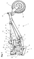
- FIG. 1 shows a first example of production of a part of an agricultural machine (1) comprising a frame (2) provided a three-point hitch system (3). It is an agricultural machine of the type scope.
- This three-point hitch system (3) is known to those skilled in the art, it allows to attach an agricultural machine (1) to the rear linkage of a tractor.
- yokes or other coupling devices can be provided. Only the upper yoke (3a) has been shown in Figure 1. The two lower yokes do not appear in the figures but their respective housings (3b, 3c) is indicated.
- the agricultural machine (1) is a machine very wide as shown in Figure 3, it has a width of work greater than the maximum width authorized to circulate on the roads.
- said agricultural machine (1) is therefore foldable. It thus comprises several parts and preferably two parts strictly identical intended to receive work units (4). These two parts are connected to said frame (2). The parts correspond in the example of embodiment shown in Figures 2 and 3 to frames (6).
- the two frames (6) are connected to said frame (2) via first respective joints (7) of axes directed in the direction of travel (A). They are arranged on either side of said frame (2) and perpendicular to the direction of advance (A). This is how these two chassis (6) are foldable towards the high for road transport (figure 4).
- the stowed position or the position of transport is obtained using articulated folding hydraulic cylinders (8) each between said frame (2) and said corresponding chassis (6).
- the supporting structure (1) is provided with at least one wheel (9). Therefore, the agricultural machine is of the type semi-transported.
- the traffic condition on the public highway of this agricultural machine (1) concerning the maximum permissible axle load rear of the tractor is therefore respected.
- the wheel (9) is arranged in the center of the machine, in the extension of said frame (2) and the tractor.
- Figure 1 shows a part of the agricultural machine (1) with its wheel (9) in the transport position.
- Figure 4 shows an agricultural machine in the configuration of transport.
- Said wheel (9) moves on the ground and pivots around an axis of rotation (9a) substantially horizontal and substantially perpendicular to the direction in advance (A).
- This wheel (9) is advantageously disposed at the rear of the agricultural machine (1).
- the wheel (9) is located as close as possible to said frame (2). This distance will be adapted according to of the work unit (4) mounted on an agricultural machine (1).
- the wheel (9) is linked to the frame (2) by means of a supporting structure (10).
- Said supporting structure (10) is connected to said frame (2) by means of second articulations (11) of axis substantially horizontal and substantially perpendicular to the direction of advance (AT).
- the direction of said second articulation (11) is therefore horizontal and orthogonal to the direction of said first articulation (7).
- This wheel (9) is connected to said support structure (10) via a fifth articulation (12) of axis substantially vertical during transport.
- Said fifth articulation (12) allows the wheel (9) to follow the movements of the tractor during movement.
- said fifth articulation (12) is located in front of the axis of rotation (9a) taking into account the direction of advance (A).
- This wheel (9) is a transport assistance wheel. She supports part of the weight of the agricultural machine (1) in the transport configuration.
- Said wheel (9) is advantageously equipped with a braking system to assist the tractor braking system during transport.
- This first hydraulic module (13) is composed of a jack double acting hydraulic (14) and a single acting hydraulic cylinder (15).
- the double-acting hydraulic cylinder (14) for lowering or raising the wheel (9) in order to be in the transport or work configuration.
- the hydraulic cylinder simple effect (15) is, for its part, mainly active during transport, being connected to an oleopneumatic accumulator (16), it advantageously allows the depreciation of the agricultural machine (1) during transport.
- This hydraulic cylinder single-acting (15) with the oleopneumatic accumulator (16) makes it possible to absorb a large part of the shocks suffered by the wheel (9) during transport.
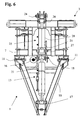
- the first hydraulic module (13) is linked to said support structure (10) via a sixth joint (17) with a horizontal axis and perpendicular to the direction in advance (A).
- the other end is linked to said frame (2) via a seventh joint (18) with a horizontal axis and perpendicular to the direction of advance (A).
- This end is advantageously linked to a yoke (19) belonging to said frame (2).
- This yoke (19) is placed at the rear of said frame (2).
- said screed (19) is located substantially in the middle of the second joints (11) of the supporting structure (10) and at a certain distance above said second joints (11).
- the seventh joint (18) and the second joints (11) are placed in such a way as to be substantially aligned with the coupling points the three-point hitch system (3).
- the two cylinders (14, 15) forming the first hydraulic module (13) have a common body (20). This one is blocked in rotation by means of a part (21). This part (21) is screwed onto said body common (20) and more particularly on the part of the body (20) forming the jack single acting hydraulic (15).
- the other end of the part (21) has a oblong hole (22). Said oblong hole (22) is linked to said clevis (19) by means of the seventh joint (18).
- the length of the oblong hole (22) is substantially greater than the stroke of the single-acting hydraulic cylinder (15) to allow the depreciation of the agricultural machine (1) during transport.
- Cylinder stroke double acting hydraulic (14) is greater than the stroke of the hydraulic cylinder single effect (15).
- the system three-point hitch (3) has a pivoting hitch head (23).
- This head coupling (23) is advantageously linked to the yoke (3a) via a fourth articulation (24) of substantially horizontal axis and substantially transverse to the direction of advance (A).
- the coupling head (23) can thus pivot forwards or backwards around the fourth joint (24).
- This coupling head (23) is intended to be linked to the connecting rod of the third point (not shown) of the tractor.
- Sure the front part of the coupling head (23) is formed a series of holes, these holes allow an adaptation of the agricultural machine (1) to different categories hitch. These different holes are aligned on the same straight line.
- the pivoting thereof is limited.
- the agricultural machine (1) is more or less free to orient themselves around the third axis formed by the two points lower hitch. It is known to modify the length of the connecting rod of the third point to increase or reduce the stitching angle of the working units (4) in the working configuration.
- the connecting rod of the third point is replaced by a hydraulic cylinder.
- the user will be able to change the cylinder length from the tractor cab.
- Said agricultural machine (1) of the present invention behaves like a machine carried in the working configuration. It is thus necessary to block the pivoting of the agricultural machine (1) in order to follow the unevenness of the field and ensure a constant working depth. In a way particularly advantageous, this pivoting around said fourth articulation (24) is blocked by a second hydraulic module (25). This last is articulated between the coupling head (23) and the yoke (19) via an eighth and a ninth joint (26, 27). Note that the different joints (7, 11, 12, 17, 18, 24, 26, 27) are pivot type joints. Furthermore during the transport, it is important that this second hydraulic module (25) is free. So when the tractor with the agricultural machine passes bumps and hollows, the stresses on the rod of the third point are zero and the machine (1) can pivot freely around said third axis.
- Said second hydraulic module (25) consists of a common body (28), a first and a second rod.
- the first rod forms with the body common (28), a first cylinder (29) and the second rod form with the body common (28) a second cylinder (30).
- Each cylinder (29, 30) is advantageously a single acting hydraulic cylinder.
- the stroke and volume of the cylinders (29, 30) are different, however it is not excluded that these two cylinders (29, 30) are identical.
- the common body (28) of said second module hydraulic (25) is locked in rotation by means of said part (21).
- Said second hydraulic module (25) advantageously makes it possible to easily find the middle position of the coupling head (23) i.e. when the holes are confused with a vertical plane.
- This position is obtained when the two jacks (29, 30) are supplied with hydraulic fluid and the pistons are in abutments. It would be imaginable to find the middle position with position sensors.
- the cylinders (29, 30) are constantly supplied with fluid, they therefore remain in abutment which makes it possible to lock the pivoting of the agricultural machine (1).
- the cylinder (29) is advantageously elongated while the jack (30) is retracted.
- the first and the second hydraulic module (13, 25) have been symbolically represented in order to deduce the position of each cylinder (14, 15, 29, 30) in the working position.
- Said agricultural machine (1) behaves like a semi-mounted machine in the transport configuration.
- the agricultural machine (1) is coupled by means of the three-point hitch system (3) and said wheel (9) rests on the ground, it is then necessary to release the agricultural machine (1) to follow the unevenness of the road. This avoids subjecting the rod of the third point to efforts important up to rupture when passing bumps.
- the cylinders (29, 30) are not supplied during transport, so they are free to lengthen or retract depending on the route.
- the different cylinders (14, 15, 29, 30) are connected via pipes respective forming a hydraulic circuit. Said hydraulic circuit is linked to the tractor hydraulic unit. This hydraulic circuit allows among other things manage the different sequences for the transition from the work configuration to the transport configuration and vice versa.
- the agricultural machine (1) is put in transport position in three phases, first of all the two frames (6) are folded around the first joints (7) by means of the corresponding folding cylinder (8). Then the wheel (9) is positioned on the ground via the first hydraulic module (13), it is the double-acting hydraulic cylinder (14) which lengthens. And finally the head coupling (23) which is unlocked, that is to say that the rods of the jacks (29, 30) are free.
- the different phases take place automatically from the control of the unfolding cylinder (8).
- the transition from the transport position to the working position, i.e. the unfolding of the agricultural machine (1) is done in reverse order, i.e. the head hitch (23) is locked by supplying the second hydraulic module (25) then the double-acting hydraulic cylinder (14) retracts causing the withdrawal of the wheel (9) and finally the folding cylinders (8) are extended to unfold the chassis respective (6).
- the machine agricultural (1) is advantageously a combined agricultural machine for work soil and sowing (100).
- Each chassis (6) is thus provided with working units (4) composed of soil working organs and an associated reference organ (101).
- AT the rear of the reference member (101) is a seed bar (102) connected to said chassis (6) corresponding using a connecting structure (103).
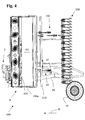
- FIG. 2 shows, in side view, the combined agricultural machine (100) according to the invention in a working position.
- Each chassis (6) is consisting of a rotary harrow beam and the soil working devices are power harrow tools (104) rotated around vertical axes.
- a casing mounted on said frame (2) makes it possible to transmit to each chassis (6) the rotational movement from the tractor PTO. This transmission is obtained using a respective drive shaft. Such training is known per se.
- Each reference member (101), for example consisting of a roller reconsolidation, is mounted on the corresponding frame (6) using an arm (105). This the latter is articulated on said chassis (6) around a localized articulation (106) of on either side of the reference member (101).
- the joint (106) has an axis transverse to the direction of advance (A). It is this arm (105) which supports the axis of rotation (101a) of said reference member (101) and which makes it possible to define the position of the latter relative to the corresponding chassis (6).
- said chassis (6) is provided with a stop means (107) against which the arm (105) comes to bear when the reference member (101) rolls on the ground.
- the stop means (107) is preferably movable in different positions and is made with all means known.
- each reference member (101) defines the depth of work, that is to say the penetration into the ground of the corresponding tools (104).
- a such an adjustment mechanism is already known.
- the arm (105) also comprises a support (108) comprising means for cleaning the reference member (101). In the example shown in figures, it is a stripper of the consolidation roller.
- the support (108) is by example fixed on the arm (105) with any known means, for example screws (109).
- Each seed bar (102) consists of a crosspiece (110) extending transverse to the direction of advance (A).
- the crossmember (110) supports coulters seedlings (111), which are connected via conduits (not shown) to a dispensing head (112), partially shown, of a seed drill pneumatic.
- the distribution head (112) distributes the seeds to be sown in each corresponding conduit and coulter (111).
- the distribution head (112) is of course supplied in a known manner by a pipe in communication with a hopper (not shown in the figures) mounted for example on a linkage front of the tractor.
- Each seed bar (102) is linked to the corresponding frame (6) by through a connecting structure (113) allowing said seed bar (102) to move in height with respect to said chassis (6) and with respect to the corresponding reference member (101).
- the connecting structure (113) is formed by a beam (114) fitted with holding devices (115) for the crosspieces (110).
- the seed bar (102) being in two parts, each mounted on a beam corresponding (114).
- Said beams (114) are linked to said link arms (105) the reference member (101) to said chassis (6) by means of articulations (116).
- the position of each beam (114) is adjustable around said joints (116) at the by means of a hydraulic position cylinder (117).
- Holding devices (115) are fixed on the one hand on the beam (114) and on the other hand on the crosspiece (110). So the seed coulters (111) with their respective crosspiece (110) can be placed or removed from their working position via the hydraulic cylinders of position (117) articulated between said respective chassis (6) and said device respective hold (115).
- the seed coulters (111) mounted on the crossbars (110) are not shown in their entirety so as not to unnecessarily overload the figures.
- the holding devices (115) also serve as a support for a power harrow.
- corresponding cover (118) intended to follow the sowing coulters (111). of the mounting and adjustment means suitable for each harrow (118) can also be provided.
- the pneumatic seed drill is replaced by a mechanical seed drill.
- the combined agricultural machine (100) also comprises a control means serving to raise and lower a seed bar (102) relative to the reference member (101) corresponding.
- the lifting of said seed bar (102) with respect to said reference member (101) can be useful during maneuvers after plot or to carry out only a tillage operation (without sowing) with the combined agricultural machine (100). This can be useful for specific preparations for a seedbed.
- the combined agricultural machine (100) also has a retaining means for the two vertically folding parts for transport on roads.
- Such relative movements between said seed bar (102) and the frame (6) corresponding would indeed generate, during transport, harmful shocks, terms, for the various articulations and for the stability of the agricultural machine combined (100).
- each seed bar (102) relative to the corresponding reference (101) allows the user to perform the maneuvers at the end of the plots, but also to carry out exclusively a tillage operation.
- the machine agricultural (1) is supported by a double wheel (9 ').
- this double wheel (9 ') is equipped with a braking system integrated allowing assistance during transport.
- An agricultural machine (1) provided with such a double wheel (9 ') is more stable during maneuvers.
- the agricultural machine (1) is a machine for harvesting fodder.
- the work unit supported by the chassis is a mowing group. This can be done with a cutter bar alone, a bar cutting and a packaging device with or without swath grouper.
- the wheels (9, 9 ') being arranged above the machine during work and cutting and / or assembling the forage does not deteriorate the quality fodder.
Landscapes
- Life Sciences & Earth Sciences (AREA)
- Engineering & Computer Science (AREA)
- Mechanical Engineering (AREA)
- Soil Sciences (AREA)
- Environmental Sciences (AREA)
- Agricultural Machines (AREA)
Abstract
Description
- un cadre destiné à être accroché à un tracteur au moyen d'un système d'attelage trois points comportant deux points d'attelage inférieurs et un point d'attelage supérieur ;
- au moins deux châssis reliés audit cadre de manière repliable autour d'une première articulation respective ;
- au moins une unité de travail montée sur chacun desdits châssis.
- la figure 1 représente selon un premier exemple de réalisation d'une machine agricole conforme à la présente invention ;
- la figure 2 représente selon un deuxième exemple de réalisation une vue de profil d'une machine agricole combinée conforme à l'invention, placée dans une position de travail ;
- la figure 3 représente une vue de dessus d'une machine agricole combinée de la figure 2, placée dans une position de travail ;
- la figure 4 représente, en vue de côté, la machine agricole combinée placée en position repliée de transport ;
- la figure 5 représente la machine agricole de la figure 1 dans la configuration de travail ;
- la figure 6 représente une vue de dessus, à une plus grande échelle, de la figure 5.
Claims (20)
- Machine agricole (1 ; 100) comprenant :caractérisée en ce qu'une structure porteuse (10) supporte au moins une roue (9) et est liée audit cadre (2) via une deuxième articulation (11), le pivotement de ladite structure porteuse (10) autour de ladite deuxième articulation (11) étant commandé par un premier module hydraulique (13).un cadre (2) destiné à être accroché à un tracteur au moyen d'un système d'attelage trois points (3) comportant deux points d'attelage inférieurs et un point d'attelage supérieur ;au moins deux châssis (6) reliés audit cadre (2) de manière repliable autour d'une première articulation (7) respective ;au moins une unité de travail (4) montée sur chacun desdits châssis (6) ;
- Machine agricole selon la revendication 1, caractérisée en ce que ladite(lesdites) roue(s) (9) n'est(ne sont) pas utilisée(s) au travail.
- Machine agricole selon la revendication 1 ou 2, caractérisée en ce qu'au transport ladite machine agricole (1 ; 100) pivote librement autour d'un troisième axe formé par les deux points d'attelage inférieurs.
- Machine agricole selon la revendication 3, caractérisée en ce que le pivotement de ladite machine agricole (1 ; 100) est limité par un deuxième module hydraulique (25).
- Machine agricole selon la revendication 4, caractérisée en ce que ledit cadre (2) comporte une tête d'attelage (23) pivotante définissant le point d'attelage supérieur.
- Machine agricole selon l'une quelconque des revendications 3 à 5, caractérisée en ce que ladite tête d'attelage (23) pivote autour d'une quatrième articulation (24) sensiblement parallèle audit troisième axe formé par les deux points d'attelage inférieurs.
- Machine agricole selon l'une quelconque des revendications 4 à 6, caractérisée en ce que ledit deuxième module hydraulique (25) est articulé entre ladite tête d'attelage (23) et ledit cadre (2).
- Machine agricole selon l'une quelconque des revendications 4 à 7, caractérisée en ce que le pivotement de ladite tête d'attelage (23) est bloqué par ledit deuxième module hydraulique (25) au travail.
- Machine agricole selon l'une quelconque des revendications 4 à 8, caractérisée en ce que la position médiane de la tête d'attelage (23) est définie grâce audit deuxième module hydraulique (25).
- Machine agricole selon l'une quelconque des revendications 4 à 9, caractérisée en ce que ledit deuxième module hydraulique (25) est composé de deux vérins (29, 30).
- Machine agricole selon l'une quelconque des revendications 1 à 10, caractérisée en ce que ledit premier module hydraulique (13) comporte deux vérins (14, 15).
- Machine agricole selon la revendication 10 et 11, caractérisée en ce que lesdits vérins (14, 15) dudit premier module hydraulique (13) comportent un corps commun (20) et que lesdits vérins (29, 30) dudit deuxième module hydraulique (25) comportent aussi un corps commun (28).
- Machine agricole selon les revendications 1 et 12, caractérisée en ce que l'un des vérins (14 ; 15) dudit premier module hydraulique (13) est relié à un accumulateur oléopneumatique (16).
- Machine agricole selon l'une quelconque des revendications 1 à 13, caractérisée en ce que ladite première articulation (7) comporte un axe sensiblement dans la direction d'avance (A) et ladite deuxième articulation (11) comporte un axe sensiblement horizontal et orthogonal à ladite première articulation (7).
- Machine agricole selon l'une quelconque des revendications 1 à 14, caractérisée en ce que ladite(lesdites) roue(s) (9) est(sont) pivotante autour d'une cinquième articulation (12).
- Machine agricole selon l'une quelconque des revendications 1 à 15, caractérisée en ce que ladite cinquième articulation (12) se trouve devant l'axe de rotation (9a) de ladite(lesdites) roue(s) (9).
- Machine agricole selon l'une quelconque des revendications 1 à 16, caractérisée en ce que ladite cinquième articulation (12) est sensiblement verticale au transport.
- Machine agricole selon l'une quelconque des revendications 1 à 17, caractérisée en ce que ladite(lesdites) roue(s) (9) permet(tent) l'assistance au freinage pour le transport sur route.
- Machine agricole selon l'une quelconque des revendications 1 à 18, caractérisée en ce que la roue (9) est une roue double (9').
- Machine agricole selon la revendication 1 à 19, caractérisée en ce que le passage de la position de travail à la position de transport et inversement est géré de manière séquentielle.
Applications Claiming Priority (2)
| Application Number | Priority Date | Filing Date | Title |
|---|---|---|---|
| FR0304280A FR2853204B1 (fr) | 2003-04-07 | 2003-04-07 | Machine agricole portee comportant au moins une roue d'assistance au transport |
| FR0304280 | 2003-04-07 |
Publications (2)
| Publication Number | Publication Date |
|---|---|
| EP1466516A1 true EP1466516A1 (fr) | 2004-10-13 |
| EP1466516B1 EP1466516B1 (fr) | 2013-08-28 |
Family
ID=32865385
Family Applications (1)
| Application Number | Title | Priority Date | Filing Date |
|---|---|---|---|
| EP20040360035 Expired - Lifetime EP1466516B1 (fr) | 2003-04-07 | 2004-04-06 | Machine agricole comportant au moins une roue |
Country Status (3)
| Country | Link |
|---|---|
| EP (1) | EP1466516B1 (fr) |
| DK (1) | DK1466516T3 (fr) |
| FR (1) | FR2853204B1 (fr) |
Cited By (2)
| Publication number | Priority date | Publication date | Assignee | Title |
|---|---|---|---|---|
| WO2013134836A1 (fr) * | 2012-03-15 | 2013-09-19 | Stara S/A. Indústria De Implementos Agrícolas | Système de transmission de mouvement, adapté en système de roulement auto-compensateur dans le sens longitudinal, trouvant une application dans des machines et des outils agricoles |
| EP4124221A1 (fr) | 2021-07-28 | 2023-02-01 | Kverneland Group Soest GmbH | Machine agricole et combinaison de machines agricoles |
Citations (6)
| Publication number | Priority date | Publication date | Assignee | Title |
|---|---|---|---|---|
| DE3033848A1 (de) * | 1980-09-09 | 1982-03-18 | Rabewerk Heinrich Clausing, 4515 Bad Essen | Kombinationsgeraet fuer die bodenbearbeitung |
| DE3605975A1 (de) * | 1985-11-04 | 1987-08-27 | Otto Fritz Ulrich Dipl Agr Ing | Nachlaeuferkombination fuer wendepacker |
| EP0513939A2 (fr) | 1986-11-04 | 1992-11-19 | C. van der Lely N.V. | Machine pour le travail du sol |
| US5577563A (en) * | 1995-07-27 | 1996-11-26 | Holen; Kurt | Stack-folding toolbar with floating wings |
| US20010045294A1 (en) * | 1998-10-30 | 2001-11-29 | Mayerle Dean J. | Agricultural ground working implement with hydraulic downpressure circuit |
| US6345490B1 (en) * | 1998-10-30 | 2002-02-12 | Kuhn S.A. | Agricultural machine including a locking mechanism for preventing a double-rod ram from rotating around its longitudinal axis |
-
2003
- 2003-04-07 FR FR0304280A patent/FR2853204B1/fr not_active Expired - Fee Related
-
2004
- 2004-04-06 DK DK04360035T patent/DK1466516T3/da active
- 2004-04-06 EP EP20040360035 patent/EP1466516B1/fr not_active Expired - Lifetime
Patent Citations (6)
| Publication number | Priority date | Publication date | Assignee | Title |
|---|---|---|---|---|
| DE3033848A1 (de) * | 1980-09-09 | 1982-03-18 | Rabewerk Heinrich Clausing, 4515 Bad Essen | Kombinationsgeraet fuer die bodenbearbeitung |
| DE3605975A1 (de) * | 1985-11-04 | 1987-08-27 | Otto Fritz Ulrich Dipl Agr Ing | Nachlaeuferkombination fuer wendepacker |
| EP0513939A2 (fr) | 1986-11-04 | 1992-11-19 | C. van der Lely N.V. | Machine pour le travail du sol |
| US5577563A (en) * | 1995-07-27 | 1996-11-26 | Holen; Kurt | Stack-folding toolbar with floating wings |
| US20010045294A1 (en) * | 1998-10-30 | 2001-11-29 | Mayerle Dean J. | Agricultural ground working implement with hydraulic downpressure circuit |
| US6345490B1 (en) * | 1998-10-30 | 2002-02-12 | Kuhn S.A. | Agricultural machine including a locking mechanism for preventing a double-rod ram from rotating around its longitudinal axis |
Cited By (3)
| Publication number | Priority date | Publication date | Assignee | Title |
|---|---|---|---|---|
| WO2013134836A1 (fr) * | 2012-03-15 | 2013-09-19 | Stara S/A. Indústria De Implementos Agrícolas | Système de transmission de mouvement, adapté en système de roulement auto-compensateur dans le sens longitudinal, trouvant une application dans des machines et des outils agricoles |
| EP4124221A1 (fr) | 2021-07-28 | 2023-02-01 | Kverneland Group Soest GmbH | Machine agricole et combinaison de machines agricoles |
| WO2023006233A1 (fr) | 2021-07-28 | 2023-02-02 | Kverneland Group Soest Gmbh | Machine agricole et combinaison de machines agricoles |
Also Published As
| Publication number | Publication date |
|---|---|
| EP1466516B1 (fr) | 2013-08-28 |
| FR2853204B1 (fr) | 2006-02-03 |
| FR2853204A1 (fr) | 2004-10-08 |
| DK1466516T3 (da) | 2013-12-02 |
Similar Documents
| Publication | Publication Date | Title |
|---|---|---|
| EP0429381B1 (fr) | Machine agricole avec dispositif de suspension du groupe d'organes de travail perfectionné | |
| EP1366650B1 (fr) | Machine agricole comportant un dispositif de mise en transport | |
| EP1965630B1 (fr) | Engin agricole comportant un attelage perfectionne | |
| EP2699074B1 (fr) | Machine agricole avec un dispositif de repliage perfectionne | |
| FR2746576A1 (fr) | Machine agricole du genre faneuse a rateaux rotatifs multiples, convertible d'une position de travail deployee a une position de transport ramassee | |
| EP2538762B1 (fr) | Semoir repliable perfectionne | |
| EP1959722B1 (fr) | Combiné de semis | |
| EP2361491B1 (fr) | Semoir avec dispositifs de réglage à encombrement réduit | |
| EP2353351A1 (fr) | Charrue semi-portée réversible hors raie | |
| EP1466516B1 (fr) | Machine agricole comportant au moins une roue | |
| EP1639880A1 (fr) | Andaineuse de végétaux | |
| EP2547189A1 (fr) | Semoir avec un chassis traine | |
| EP1029432B1 (fr) | Semoir | |
| FR2693345A1 (fr) | Faucheuse destinée à être liée à un véhicule moteur et comportant un dispositif de dépose perfectionné. | |
| EP0966875B1 (fr) | Semoir | |
| FR2831387A1 (fr) | Machine agricole travaillant sur plusieurs rangees avec des outils | |
| FR2544161A1 (fr) | Machine pour l'epandage pneumatique notamment de matieres en grains | |
| EP0486415B1 (fr) | Faucheuse à châssis indépendant comportant un dispositif de suspension et un dispositif d'allègement perfectionnés | |
| EP2106681B1 (fr) | Machine agricole avec un chariot perfectionné | |
| FR2901452A1 (fr) | Machine agricole pouvant etre attelee a l'arriere d'un tracteur par l'intermediaire d'une poutre semi-portee | |
| FR2920947A1 (fr) | Andaineuse |
Legal Events
| Date | Code | Title | Description |
|---|---|---|---|
| PUAI | Public reference made under article 153(3) epc to a published international application that has entered the european phase |
Free format text: ORIGINAL CODE: 0009012 |
|
| AK | Designated contracting states |
Kind code of ref document: A1 Designated state(s): AT BE BG CH CY CZ DE DK EE ES FI FR GB GR HU IE IT LI LU MC NL PL PT RO SE SI SK TR |
|
| AX | Request for extension of the european patent |
Extension state: AL HR LT LV MK |
|
| 17P | Request for examination filed |
Effective date: 20050413 |
|
| AKX | Designation fees paid |
Designated state(s): AT BE BG CH CY CZ DE DK EE ES FI FR GB GR HU IE IT LI LU MC NL PL PT RO SE SI SK TR |
|
| 17Q | First examination report despatched |
Effective date: 20081029 |
|
| GRAP | Despatch of communication of intention to grant a patent |
Free format text: ORIGINAL CODE: EPIDOSNIGR1 |
|
| GRAP | Despatch of communication of intention to grant a patent |
Free format text: ORIGINAL CODE: EPIDOSNIGR1 |
|
| GRAS | Grant fee paid |
Free format text: ORIGINAL CODE: EPIDOSNIGR3 |
|
| GRAA | (expected) grant |
Free format text: ORIGINAL CODE: 0009210 |
|
| INTG | Intention to grant announced |
Effective date: 20130701 |
|
| AK | Designated contracting states |
Kind code of ref document: B1 Designated state(s): AT BE BG CH CY CZ DE DK EE ES FI FR GB GR HU IE IT LI LU MC NL PL PT RO SE SI SK TR |
|
| REG | Reference to a national code |
Ref country code: GB Ref legal event code: FG4D Free format text: NOT ENGLISH |
|
| REG | Reference to a national code |
Ref country code: CH Ref legal event code: EP |
|
| REG | Reference to a national code |
Ref country code: AT Ref legal event code: REF Ref document number: 628749 Country of ref document: AT Kind code of ref document: T Effective date: 20130915 |
|
| REG | Reference to a national code |
Ref country code: IE Ref legal event code: FG4D Free format text: LANGUAGE OF EP DOCUMENT: FRENCH |
|
| REG | Reference to a national code |
Ref country code: DE Ref legal event code: R096 Ref document number: 602004043175 Country of ref document: DE Effective date: 20131024 |
|
| REG | Reference to a national code |
Ref country code: DK Ref legal event code: T3 Effective date: 20131128 |
|
| REG | Reference to a national code |
Ref country code: NL Ref legal event code: VDEP Effective date: 20130828 |
|
| PG25 | Lapsed in a contracting state [announced via postgrant information from national office to epo] |
Ref country code: PT Free format text: LAPSE BECAUSE OF FAILURE TO SUBMIT A TRANSLATION OF THE DESCRIPTION OR TO PAY THE FEE WITHIN THE PRESCRIBED TIME-LIMIT Effective date: 20131230 Ref country code: SE Free format text: LAPSE BECAUSE OF FAILURE TO SUBMIT A TRANSLATION OF THE DESCRIPTION OR TO PAY THE FEE WITHIN THE PRESCRIBED TIME-LIMIT Effective date: 20130828 Ref country code: CY Free format text: LAPSE BECAUSE OF FAILURE TO SUBMIT A TRANSLATION OF THE DESCRIPTION OR TO PAY THE FEE WITHIN THE PRESCRIBED TIME-LIMIT Effective date: 20130703 |
|
| REG | Reference to a national code |
Ref country code: NL Ref legal event code: VDEP Effective date: 20130828 |
|
| PG25 | Lapsed in a contracting state [announced via postgrant information from national office to epo] |
Ref country code: PL Free format text: LAPSE BECAUSE OF FAILURE TO SUBMIT A TRANSLATION OF THE DESCRIPTION OR TO PAY THE FEE WITHIN THE PRESCRIBED TIME-LIMIT Effective date: 20130828 Ref country code: GR Free format text: LAPSE BECAUSE OF FAILURE TO SUBMIT A TRANSLATION OF THE DESCRIPTION OR TO PAY THE FEE WITHIN THE PRESCRIBED TIME-LIMIT Effective date: 20131129 Ref country code: FI Free format text: LAPSE BECAUSE OF FAILURE TO SUBMIT A TRANSLATION OF THE DESCRIPTION OR TO PAY THE FEE WITHIN THE PRESCRIBED TIME-LIMIT Effective date: 20130828 Ref country code: ES Free format text: LAPSE BECAUSE OF FAILURE TO SUBMIT A TRANSLATION OF THE DESCRIPTION OR TO PAY THE FEE WITHIN THE PRESCRIBED TIME-LIMIT Effective date: 20130828 Ref country code: SI Free format text: LAPSE BECAUSE OF FAILURE TO SUBMIT A TRANSLATION OF THE DESCRIPTION OR TO PAY THE FEE WITHIN THE PRESCRIBED TIME-LIMIT Effective date: 20130828 |
|
| PG25 | Lapsed in a contracting state [announced via postgrant information from national office to epo] |
Ref country code: CY Free format text: LAPSE BECAUSE OF FAILURE TO SUBMIT A TRANSLATION OF THE DESCRIPTION OR TO PAY THE FEE WITHIN THE PRESCRIBED TIME-LIMIT Effective date: 20130828 |
|
| PG25 | Lapsed in a contracting state [announced via postgrant information from national office to epo] |
Ref country code: EE Free format text: LAPSE BECAUSE OF FAILURE TO SUBMIT A TRANSLATION OF THE DESCRIPTION OR TO PAY THE FEE WITHIN THE PRESCRIBED TIME-LIMIT Effective date: 20130828 Ref country code: RO Free format text: LAPSE BECAUSE OF FAILURE TO SUBMIT A TRANSLATION OF THE DESCRIPTION OR TO PAY THE FEE WITHIN THE PRESCRIBED TIME-LIMIT Effective date: 20130828 Ref country code: CZ Free format text: LAPSE BECAUSE OF FAILURE TO SUBMIT A TRANSLATION OF THE DESCRIPTION OR TO PAY THE FEE WITHIN THE PRESCRIBED TIME-LIMIT Effective date: 20130828 Ref country code: SK Free format text: LAPSE BECAUSE OF FAILURE TO SUBMIT A TRANSLATION OF THE DESCRIPTION OR TO PAY THE FEE WITHIN THE PRESCRIBED TIME-LIMIT Effective date: 20130828 Ref country code: NL Free format text: LAPSE BECAUSE OF FAILURE TO SUBMIT A TRANSLATION OF THE DESCRIPTION OR TO PAY THE FEE WITHIN THE PRESCRIBED TIME-LIMIT Effective date: 20130828 |
|
| REG | Reference to a national code |
Ref country code: DE Ref legal event code: R097 Ref document number: 602004043175 Country of ref document: DE |
|
| PLBE | No opposition filed within time limit |
Free format text: ORIGINAL CODE: 0009261 |
|
| STAA | Information on the status of an ep patent application or granted ep patent |
Free format text: STATUS: NO OPPOSITION FILED WITHIN TIME LIMIT |
|
| 26N | No opposition filed |
Effective date: 20140530 |
|
| REG | Reference to a national code |
Ref country code: DE Ref legal event code: R097 Ref document number: 602004043175 Country of ref document: DE Effective date: 20140530 |
|
| PG25 | Lapsed in a contracting state [announced via postgrant information from national office to epo] |
Ref country code: MC Free format text: LAPSE BECAUSE OF FAILURE TO SUBMIT A TRANSLATION OF THE DESCRIPTION OR TO PAY THE FEE WITHIN THE PRESCRIBED TIME-LIMIT Effective date: 20130828 Ref country code: LU Free format text: LAPSE BECAUSE OF FAILURE TO SUBMIT A TRANSLATION OF THE DESCRIPTION OR TO PAY THE FEE WITHIN THE PRESCRIBED TIME-LIMIT Effective date: 20140406 |
|
| REG | Reference to a national code |
Ref country code: CH Ref legal event code: PL |
|
| GBPC | Gb: european patent ceased through non-payment of renewal fee |
Effective date: 20140406 |
|
| REG | Reference to a national code |
Ref country code: IE Ref legal event code: MM4A |
|
| PG25 | Lapsed in a contracting state [announced via postgrant information from national office to epo] |
Ref country code: LI Free format text: LAPSE BECAUSE OF NON-PAYMENT OF DUE FEES Effective date: 20140430 Ref country code: CH Free format text: LAPSE BECAUSE OF NON-PAYMENT OF DUE FEES Effective date: 20140430 Ref country code: GB Free format text: LAPSE BECAUSE OF NON-PAYMENT OF DUE FEES Effective date: 20140406 |
|
| PG25 | Lapsed in a contracting state [announced via postgrant information from national office to epo] |
Ref country code: IE Free format text: LAPSE BECAUSE OF NON-PAYMENT OF DUE FEES Effective date: 20140406 |
|
| REG | Reference to a national code |
Ref country code: FR Ref legal event code: PLFP Year of fee payment: 13 |
|
| PG25 | Lapsed in a contracting state [announced via postgrant information from national office to epo] |
Ref country code: BG Free format text: LAPSE BECAUSE OF FAILURE TO SUBMIT A TRANSLATION OF THE DESCRIPTION OR TO PAY THE FEE WITHIN THE PRESCRIBED TIME-LIMIT Effective date: 20130828 |
|
| PG25 | Lapsed in a contracting state [announced via postgrant information from national office to epo] |
Ref country code: HU Free format text: LAPSE BECAUSE OF FAILURE TO SUBMIT A TRANSLATION OF THE DESCRIPTION OR TO PAY THE FEE WITHIN THE PRESCRIBED TIME-LIMIT; INVALID AB INITIO Effective date: 20040406 Ref country code: BE Free format text: LAPSE BECAUSE OF FAILURE TO SUBMIT A TRANSLATION OF THE DESCRIPTION OR TO PAY THE FEE WITHIN THE PRESCRIBED TIME-LIMIT Effective date: 20140430 Ref country code: TR Free format text: LAPSE BECAUSE OF FAILURE TO SUBMIT A TRANSLATION OF THE DESCRIPTION OR TO PAY THE FEE WITHIN THE PRESCRIBED TIME-LIMIT Effective date: 20130828 |
|
| PGFP | Annual fee paid to national office [announced via postgrant information from national office to epo] |
Ref country code: IT Payment date: 20160324 Year of fee payment: 13 Ref country code: AT Payment date: 20160323 Year of fee payment: 13 |
|
| REG | Reference to a national code |
Ref country code: FR Ref legal event code: PLFP Year of fee payment: 14 |
|
| REG | Reference to a national code |
Ref country code: AT Ref legal event code: MM01 Ref document number: 628749 Country of ref document: AT Kind code of ref document: T Effective date: 20170406 |
|
| PG25 | Lapsed in a contracting state [announced via postgrant information from national office to epo] |
Ref country code: AT Free format text: LAPSE BECAUSE OF NON-PAYMENT OF DUE FEES Effective date: 20170406 |
|
| REG | Reference to a national code |
Ref country code: FR Ref legal event code: PLFP Year of fee payment: 15 |
|
| PG25 | Lapsed in a contracting state [announced via postgrant information from national office to epo] |
Ref country code: IT Free format text: LAPSE BECAUSE OF NON-PAYMENT OF DUE FEES Effective date: 20170406 |
|
| PGFP | Annual fee paid to national office [announced via postgrant information from national office to epo] |
Ref country code: PT Payment date: 20190222 Year of fee payment: 16 |
|
| REG | Reference to a national code |
Ref country code: DK Ref legal event code: EBP Effective date: 20200430 |
|
| PG25 | Lapsed in a contracting state [announced via postgrant information from national office to epo] |
Ref country code: DK Free format text: LAPSE BECAUSE OF NON-PAYMENT OF DUE FEES Effective date: 20200430 |
|
| PGFP | Annual fee paid to national office [announced via postgrant information from national office to epo] |
Ref country code: FR Payment date: 20210426 Year of fee payment: 18 Ref country code: DE Payment date: 20210428 Year of fee payment: 18 |
|
| REG | Reference to a national code |
Ref country code: DE Ref legal event code: R119 Ref document number: 602004043175 Country of ref document: DE |
|
| PG25 | Lapsed in a contracting state [announced via postgrant information from national office to epo] |
Ref country code: FR Free format text: LAPSE BECAUSE OF NON-PAYMENT OF DUE FEES Effective date: 20220430 Ref country code: DE Free format text: LAPSE BECAUSE OF NON-PAYMENT OF DUE FEES Effective date: 20221103 |