EP1465774B1 - Method for reducing variations in print density - Google Patents
Method for reducing variations in print density Download PDFInfo
- Publication number
- EP1465774B1 EP1465774B1 EP03705654A EP03705654A EP1465774B1 EP 1465774 B1 EP1465774 B1 EP 1465774B1 EP 03705654 A EP03705654 A EP 03705654A EP 03705654 A EP03705654 A EP 03705654A EP 1465774 B1 EP1465774 B1 EP 1465774B1
- Authority
- EP
- European Patent Office
- Prior art keywords
- nozzles
- print density
- output
- drops
- Prior art date
- Legal status (The legal status is an assumption and is not a legal conclusion. Google has not performed a legal analysis and makes no representation as to the accuracy of the status listed.)
- Expired - Lifetime
Links
- 238000000034 method Methods 0.000 title claims abstract description 35
- 239000000758 substrate Substances 0.000 claims description 15
- 230000002950 deficient Effects 0.000 claims description 10
- 238000012937 correction Methods 0.000 description 15
- 238000013459 approach Methods 0.000 description 14
- 230000001186 cumulative effect Effects 0.000 description 3
- 238000010586 diagram Methods 0.000 description 3
- 238000012986 modification Methods 0.000 description 2
- 230000004048 modification Effects 0.000 description 2
- 230000015556 catabolic process Effects 0.000 description 1
- 125000004122 cyclic group Chemical group 0.000 description 1
- 238000006731 degradation reaction Methods 0.000 description 1
- 238000001739 density measurement Methods 0.000 description 1
- 238000006073 displacement reaction Methods 0.000 description 1
- 230000000694 effects Effects 0.000 description 1
- 238000010304 firing Methods 0.000 description 1
- 238000009499 grossing Methods 0.000 description 1
- 238000012423 maintenance Methods 0.000 description 1
- 230000003287 optical effect Effects 0.000 description 1
- 230000000737 periodic effect Effects 0.000 description 1
- 238000009877 rendering Methods 0.000 description 1
- 238000005096 rolling process Methods 0.000 description 1
- 238000012216 screening Methods 0.000 description 1
- 230000000007 visual effect Effects 0.000 description 1
Images




Classifications
-
- B—PERFORMING OPERATIONS; TRANSPORTING
- B41—PRINTING; LINING MACHINES; TYPEWRITERS; STAMPS
- B41J—TYPEWRITERS; SELECTIVE PRINTING MECHANISMS, i.e. MECHANISMS PRINTING OTHERWISE THAN FROM A FORME; CORRECTION OF TYPOGRAPHICAL ERRORS
- B41J2/00—Typewriters or selective printing mechanisms characterised by the printing or marking process for which they are designed
- B41J2/005—Typewriters or selective printing mechanisms characterised by the printing or marking process for which they are designed characterised by bringing liquid or particles selectively into contact with a printing material
- B41J2/01—Ink jet
- B41J2/21—Ink jet for multi-colour printing
- B41J2/2132—Print quality control characterised by dot disposition, e.g. for reducing white stripes or banding
- B41J2/2139—Compensation for malfunctioning nozzles creating dot place or dot size errors
Definitions
- the present invention relates to the field of printing and, in particular, it concerns a method for reducing variations in print density particularly suitable for use in inkjet printers.
- any problem of non-uniformity of the printed output which is caused by features of the print head will appear in the printed output as a regular pattern corresponding to the movements of the print head over the substrate.
- One well known technique for reducing the visibility of these cyclic variations is multi-pass printing in which the print head passes over each region of the substrate to be printed two or more times with overlapping swaths. Although this technique tends to attenuate the variations and increases the spatial frequency of the variations, it does not achieve uniformity of output.
- Hiramatsu et al. While the approach of Hiramatsu et al. is theoretically correct, implementation of this approach is in most cases complicated and over costly. Specifically, a typical inkjet printer has thousands, and often tens of thousands, of nozzles operating simultaneously. The hardware requirements to enable selective adjustment of either the actuating voltage or the pulse duration for individual nozzles are typically prohibitively expensive.
- Document US 5,528,270 describes an image forming apparatus comprising correction means for the recording elements of a recording head.
- the present invention is a method for reducing variations in output print density from an inkjet printer.
- a method for reducing variations in print density in a printed output on a substrate resulting from defective nozzles of a print head comprising: (a) obtaining a print density distribution for at least part of the print head, the print density distribution being indicative of at least one region of reduced print density due to defective nozzles; (b) assigning output reduction factors between 1% and 99% to a plurality of nozzles which are positioned within the print head so as to contribute to print density within the at least one region; (c) receiving data corresponding to an image to be printed; and (d) applying drops of ink to the substrate while passing the print head over the substrate, wherein numbers of ink drops applied to the substrate along lines traveled by each of the plurality of nozzles are increased as a function of a corresponding one of the output reduction factors.
- each of the output reduction factors is generated as a function of print density over a region covered by a plurality of nozzles.
- each of the output reduction factors is generated as a function of print density as measured by scanning a sample output at a resolution lower than the printing resolution of the print head.
- the numbers of drops are increased by printing selected dots along the lines twice using two distinct nozzles during two passes of the print head.
- the numbers of drops are increased by modifying screen values in a portion of a screen associated with locations to be printed by the plurality of nozzles.
- the present invention is a method for reducing variations in output print density from an inkjet printer.
- Figures 1-4 describe a schematic example of the problem to which the invention relates.
- a printed output of uniform 50% print density is desired.
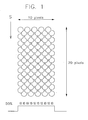
- An idealized representation of the desired output is shown in Figure 1 .
- the illustrated pattern is assumed to be produced by a line of 10 nozzles passing in a scanning direction S. Each nozzle ejects a drop at alternate pixel positions such that, in the illustrated region of 20 pixels length, each nozzle prints 10 dots.
- the resultant printed density when all nozzles are working properly, is considered to be 50% nominal coverage.
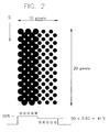
- Figure 2 illustrates the results of an attempt to print the pattern of Figure 1 with an imperfect print head in which the five nozzles responsible for printing the five rows on the left-hand-side of the figure are operating properly and the five nozzles responsible for printing the five rows on the right-hand-side of the figure are producing a reduced output.
- the resultant print density on the right side of the output may be assumed to be approximately 0.83 of the intended 50% density, namely 41.5%. The result would be clear bands of reduced density in the printed output.
- Figures 3A-3C and 4 show the results of printing with the same print head in two passes with a two-pixel offset.
- the first pass shown in Figure 3A , prints half the data for 8 rows in the region of interest (as well as 2 rows outside to the left which are not shown). Of these, three rows print regular size drops and five print small drops. Each row prints alternate drops of the 50% pattern of Figure 1 (i.e., one drop every four pixels).
- the second pass shown in Figure 3B , prints half the data for all 10 rows, five using regular drops and five using small drops.
- the third pass shown in Figure 3C , prints the remaining half of the data for the last two rows using regular size drops.
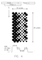
- Figure 4 shows the cumulative effect of these outputs. Referring to the rows by numbers 1-10 from left to right, rows 1-3 have each received their full quota of 10 regular size drops, rows 4, 5, 9 and 10 have received 5 regular drops and 5 small drops, and rows 6-8 have received 10 small drops. The result is a somewhat smoothed variation of printed density, but with the same range of variation from the intended 50% down to 41.5% and consequent degradation of the printed output.
- the invention provides a method for reducing undesired variations of print density in a printed output by selectively increasing the number of drops of ink deposited in rows traveled by nozzles corresponding to a reduced-output region of the print head compared to the pattern of drops which would be deposited if all nozzles were operating normally.
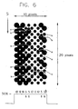
- FIG. 5A-5C and 6 The approach of the present invention is represented schematic in Figures 5A-5C and 6 . Specifically, by comparing Figures 5A and 5B with Figures 3A and 3B , respectively, it will be noted that a number of additional drops X have been deposited in rows printed by the reduced-output nozzles. In this case, each row printed by a reduced-output nozzle has one additional small drop added for each 5 small drops printed.
- Figure 6 shows the resulting overall print density in which rows 1-3 have 10 regular drops, rows 4, 5, 9 and 10 have 5 regular drops and 6 small drops, and rows 6-8 have 12 small drops. The overall result is a substantially uniform 50% coverage which, when viewed from a normal viewing distance, closely approximates to the visual effect of the ideal pattern of Figure 1 .
- the method includes obtaining a print density distribution for at least part of the print head which is indicative of at least one region of reduced print density due to defective nozzles (step 10) and assigning output reduction factors between 1% and 99% to a plurality of nozzles which are positioned within the print head so as to contribute to print density within the region of reduced print density (step 12).
- the method After receiving data corresponding to an image to be printed (step 14), the method then applies drops of ink to the substrate while passing the print head over the substrate (step 18) in such a manner as to ensure that numbers of ink drops applied to the substrate along lines traveled by each of the nozzles are increased as a function of the corresponding output reduction factor.
- the drop distribution is allocated in a step 16 at which a "corrected drop pattern" is generated.
- the present invention offers a highly advantageous solution to the problem of uneven print density.
- By adding extra drops it is possible to compensate partially or fully for regions of reduced density output from malfunctioning inkjet nozzles.
- additional discrete dots the need for nozzle-by-nozzle adjustment of the actuating voltage or pulse duration is avoided, thereby rendering the methods of the present invention easier to implement than the techniques of the Hiramatsu et al. reference discussed above.
- steps 10 and 12 may be regarded as part of a setup or maintenance procedure 20 which may be performed intermittently on demand, or may be automated to be performed on a regular basis.
- the remaining steps 14, 16 and 18 are here shown as part of a printing procedure 22 which is performed each time data is received for printing. It should be noted, however, that this subdivision is not absolute. For example, as will be discussed below, certain hardware implementation of the drop pattern correction may enable much of the correction to be performed as part of the setup procedure 20.
- the output reduction factor is an indication of the correction required, and is not necessarily set solely according to the quantity of ink ejected in each drop. For example, a misalignment of a nozzle may cause displacement of a drop so as to overlie an adjacent drop such that a proportion of the pixel to be printed by that nozzle always remains empty. This may result in an apparent "low density" region in the output despite the fact that the correct quantity of ink was actually delivered.
- the correction factors of the present invention are preferably generated as a function of print density over a region covered by a plurality of nozzles.
- correction is performed as a function of the overall print density effect in the corresponding region of the output without any need to determine which specific nozzles within that region are responsible for the print density reduction.
- One approach to achieving this result is by scanning a sample output at a resolution lower than the printing resolution of the print head. This may inherently ensure that corrections are made on the basis of variations on a scale visible to the eye.
- a similar result may be achieved by numerical techniques such as by smoothing (e.g. by a rolling average) print density measurements scanned at a high resolution.
- the correction factor is referred to herein as an "output reduction factor", it will be readily appreciated that the factor may be equivalently expressed in various different forms, including as a correction factor which is the reciprocal of the "reduction factor”. All such numerical manipulations should be clearly understood to fall within the scope of the "output reduction factor” terminology. Furthermore, any numerical factor which facilitates performance of a correction according to the teachings of the present invention will clearly be understood to be an equivalent of the recited factor.
- step 16 for generating a "corrected drop pattern" in the case of a multiple-pass printer (i.e., in which printing is performed in two or more passes).
- the received image data is processed, typically in a conventional manner, to generate driver information corresponding to which dots are to be generated during which pass of the print head.
- the dots to be printed by nozzles corresponding to reduced print density regions in each pass are identified.
- Data is then added to the driver information at step 28 to designate selected dots to be printed in duplicate during at least one other pass of the print head.
- a proportion of the dots to be printed by each nozzle with a non-zero reduction factor are printed at least twice, thereby increasing the darkness and/or coverage for those dots.
- certain dots may be printed more than two times.
- the proportion of reduced density dots duplicated is chosen according to the density reduction factor so as to provide as near as possible to optimal compensation in the overall printed image.
- Figure 8 offers a number of significant advantages. Firstly, since every dot is printed in the location in which a dot was anyway meant to be in the "ideal" output, corruption of the printed output is avoided. Secondly, this approach offers very wide dynamic range up to approaching twice the "normal" printed output, thereby allowing correction of relatively severe density irregularities. Finally, this approach may be implemented primarily through software with no modification of the hardware for driving the print head.
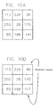
- FIGS 9 , 10A and 10B illustrate an alternative preferred implementation of the method of the present invention in which the numbers of drops is increased by selectively modifying screen values in a portion of a screen associated with locations to be printed by the defective nozzle.
- Figure 10A illustrates schematically a 3 x 3 screen element which can be applied to groups of 9 pixels each taking a values between 0 and 255 to generate 10 levels of output density.
- the values are evenly dispersed as 28, 56, 85, 113 etc.
- Figure 10B shows a similar screen element modified according to the present invention for a case in which the pixels corresponding to the right-hand column of the screen element are to be printed by a nozzle or nozzles designated as a defective nozzle group with a output reduction factor of 17%.
- the screen values of the corresponding column are reduced by 0.83, thereby correspondingly increasing the number of dots to be printed along the lines traveled by the defective nozzle group.
- step 16 of Figure 7 is effectively subdivided as shown in Figure 9 into a setup procedure 16a in which the appropriate screen values are modified and a calculation step 16 b which is essentially the standard screening procedure but performed with the modified screen values.
- the modified screen value approach has one notable advantage over the implementation of Figure 8 in that it can be used even with single-pass printing.
- a notable disadvantage is the limited dynamic range of the correction since the maximum achievable density is not enhanced by this approach.
- the increased number of dots could optionally be achieved by providing additional firing pulses to selectively "double-up" a dot.
- This approach would take advantage of the capability of inkjet nozzles to intermittently fire two drops in quick succession at a frequency greater than the normal repeat frequency. This approach would also be possible in single-pass printing.
Landscapes
- Engineering & Computer Science (AREA)
- Quality & Reliability (AREA)
- Ink Jet (AREA)
- Particle Formation And Scattering Control In Inkjet Printers (AREA)
- Facsimile Image Signal Circuits (AREA)
- Silver Salt Photography Or Processing Solution Therefor (AREA)
- Accessory Devices And Overall Control Thereof (AREA)
- Color, Gradation (AREA)
Abstract
Description
- The present invention relates to the field of printing and, in particular, it concerns a method for reducing variations in print density particularly suitable for use in inkjet printers.
- It is known that output from inkjet printers often suffers from problems of non-uniform print density. In other words, regions of the output which are intended to appear a uniform shade actually exhibit variations in shade. This is caused by a number of factors including: lack of uniformity of drop size fired by different nozzles of the print head, and varying precision of drop position from different nozzles which result in uneven coverage of the substrate.
- Any problem of non-uniformity of the printed output which is caused by features of the print head will appear in the printed output as a regular pattern corresponding to the movements of the print head over the substrate. One well known technique for reducing the visibility of these cyclic variations is multi-pass printing in which the print head passes over each region of the substrate to be printed two or more times with overlapping swaths. Although this technique tends to attenuate the variations and increases the spatial frequency of the variations, it does not achieve uniformity of output.
- A number of approaches have been proposed for providing print quality feedback to modify operation of a print head. Of most relevance to the present invention is
U.S. Patent No. 5,798,773 to Hiramatsu et al . which discloses an apparatus and method for correction of density unevenness. The apparatus employs a reader to identify unevenness in a printed calibration pattern and then performs an unevenness correction. This correction is described as being implemented "by correcting the drive signal (signal duration or voltage) of the required nozzles of the recording head" (column 5, lines 24-26), thereby varying the size of drops ejected by the inkjet nozzles in selected locations. - While the approach of Hiramatsu et al. is theoretically correct, implementation of this approach is in most cases complicated and over costly. Specifically, a typical inkjet printer has thousands, and often tens of thousands, of nozzles operating simultaneously. The hardware requirements to enable selective adjustment of either the actuating voltage or the pulse duration for individual nozzles are typically prohibitively expensive.
- There is therefore a need for a method for reducing variations in print density which would at least partially compensate for unevenness of output from a print head without requiring the complicated hardware modifications required by the Hiramatsu et al. technique.
- Document
US 5,528,270 describes an image forming apparatus comprising correction means for the recording elements of a recording head. - The present invention is a method for reducing variations in output print density from an inkjet printer.
- According to the teachings of the present invention there is provided, a method for reducing variations in print density in a printed output on a substrate resulting from defective nozzles of a print head, the method comprising: (a) obtaining a print density distribution for at least part of the print head, the print density distribution being indicative of at least one region of reduced print density due to defective nozzles; (b) assigning output reduction factors between 1% and 99% to a plurality of nozzles which are positioned within the print head so as to contribute to print density within the at least one region; (c) receiving data corresponding to an image to be printed; and (d) applying drops of ink to the substrate while passing the print head over the substrate, wherein numbers of ink drops applied to the substrate along lines traveled by each of the plurality of nozzles are increased as a function of a corresponding one of the output reduction factors.
- According to a further feature of the present invention, each of the output reduction factors is generated as a function of print density over a region covered by a plurality of nozzles.
- According to a further feature of the present invention, each of the output reduction factors is generated as a function of print density as measured by scanning a sample output at a resolution lower than the printing resolution of the print head.
- According to a further feature of the present invention, the numbers of drops are increased by printing selected dots along the lines twice using two distinct nozzles during two passes of the print head.
- According to a further feature of the present invention, the numbers of drops are increased by modifying screen values in a portion of a screen associated with locations to be printed by the plurality of nozzles.
- The invention is herein described, by way of example only, with reference to the accompanying drawings, wherein:
-
FIG. 1 is a schematic representation of an idealized printed output of uniform 50% print density which will be used to illustrate the principles of the present invention; -
FIG. 2 is a schematic representation of an actual output produced by an imperfect print head on attempting to print the pattern ofFigure 1 in a single pass; -
FIGS. 3A, 3B and 3C are schematic representations of partial printed outputs produced by the print head ofFigure 2 on attempting to print the pattern ofFigure 1 in a two-pass system; -
FIG. 4 is a schematic representation of the cumulative effect of the outputs ofFigures 3A, 3B and 3C ; -
FIGS. 5A, 5B and 5C are schematic representations of partial printed outputs produced by the print head ofFigure 2 actuated according to the teachings of the present invention to print the pattern ofFigure 1 in a two-pass system; -
FIG. 6 is a schematic representation of the cumulative effect of the outputs ofFigures 5A, 5B and 5C ; -
FIG. 7 is a flow diagram illustrating a first preferred implementation of the method of the present invention; -
FIG. 8 is a detailed flow diagram illustrating a first implementation of a step for generating a corrected drop pattern fromFigure 7 ; -
FIG. 9 is a flow diagram similar toFigure 7 modified to illustrate a second implementation of the present invention; and -
FIGS. 10A and 10B are schematic representations of screen value matrices for a group of normally functioning nozzles and for a group including reduced output nozzles according to the implementation ofFigure 9 . - The present invention is a method for reducing variations in output print density from an inkjet printer.
- The principles and operation of methods according to the present invention may be better understood with reference to the drawings and the accompanying description.
- Before addressing the invention itself, it will be useful to refer briefly to
Figures 1-4 which describe a schematic example of the problem to which the invention relates. Specifically, for the purpose of illustration, reference will be made to a case in which a printed output of uniform 50% print density is desired. An idealized representation of the desired output is shown inFigure 1 . The illustrated pattern is assumed to be produced by a line of 10 nozzles passing in a scanning direction S. Each nozzle ejects a drop at alternate pixel positions such that, in the illustrated region of 20 pixels length, each nozzle prints 10 dots. The resultant printed density, when all nozzles are working properly, is considered to be 50% nominal coverage. - At the base of this figure, as well as in
Figures 2 ,4 and6 , there is shown a schematic representation of the print density distribution. In each case, the percentage value for a given row is the sum of the drop sizes relative to the theoretical maximum of 20 full size drops. Thus, a row of 10 normal drops is defined as a nominal print density of 50%. If each drop of a given row is reduced by 17%, the percentage drops to (10 x 0.83)/20 = 41.5%, as will be discussed below with reference toFigure 2 . -
Figure 2 illustrates the results of an attempt to print the pattern ofFigure 1 with an imperfect print head in which the five nozzles responsible for printing the five rows on the left-hand-side of the figure are operating properly and the five nozzles responsible for printing the five rows on the right-hand-side of the figure are producing a reduced output. Specifically, if the defective nozzles are each producing a drop 17% smaller than the normal drop size, the resultant print density on the right side of the output may be assumed to be approximately 0.83 of the intended 50% density, namely 41.5%. The result would be clear bands of reduced density in the printed output. -
Figures 3A-3C and4 show the results of printing with the same print head in two passes with a two-pixel offset. The first pass, shown inFigure 3A , prints half the data for 8 rows in the region of interest (as well as 2 rows outside to the left which are not shown). Of these, three rows print regular size drops and five print small drops. Each row prints alternate drops of the 50% pattern ofFigure 1 (i.e., one drop every four pixels). The second pass, shown inFigure 3B , prints half the data for all 10 rows, five using regular drops and five using small drops. The third pass, shown inFigure 3C , prints the remaining half of the data for the last two rows using regular size drops. -
Figure 4 shows the cumulative effect of these outputs. Referring to the rows by numbers 1-10 from left to right, rows 1-3 have each received their full quota of 10 regular size drops,rows - Turning now to the teachings of the present invention, in its most general form, the invention provides a method for reducing undesired variations of print density in a printed output by selectively increasing the number of drops of ink deposited in rows traveled by nozzles corresponding to a reduced-output region of the print head compared to the pattern of drops which would be deposited if all nozzles were operating normally.
- The approach of the present invention is represented schematic in
Figures 5A-5C and6 . Specifically, by comparingFigures 5A and 5B withFigures 3A and 3B , respectively, it will be noted that a number of additional drops X have been deposited in rows printed by the reduced-output nozzles. In this case, each row printed by a reduced-output nozzle has one additional small drop added for each 5 small drops printed.Figure 6 shows the resulting overall print density in which rows 1-3 have 10 regular drops,rows Figure 1 . - It will be apparent to one skilled in the art that care must be taken when implementing the present invention in order to avoid corruption of the printed information. Specifically, the additional drops must not unduly darken regions of the output which are meant to be light, and they must be distributed in a dispersed and non-periodic manner so as to avoid generating unwanted artifacts. A number of specific preferred implementations will now be described with reference to
Figures 7-10 . It should be appreciated, however, that the invention in its most general form is not limited to these specific examples and may be implemented in numerous other forms, as will be clear to one ordinarily skilled in the art. - Turning now to
Figure 7 , this illustrates a first preferred implementation of a method according to the present invention for reducing variations in print density in a printed output on a substrate resulting from defective nozzles of a print head. Generally speaking, the method includes obtaining a print density distribution for at least part of the print head which is indicative of at least one region of reduced print density due to defective nozzles (step 10) and assigning output reduction factors between 1% and 99% to a plurality of nozzles which are positioned within the print head so as to contribute to print density within the region of reduced print density (step 12). After receiving data corresponding to an image to be printed (step 14), the method then applies drops of ink to the substrate while passing the print head over the substrate (step 18) in such a manner as to ensure that numbers of ink drops applied to the substrate along lines traveled by each of the nozzles are increased as a function of the corresponding output reduction factor. In the implementation shown here, the drop distribution is allocated in astep 16 at which a "corrected drop pattern" is generated. - It will be readily appreciated that the present invention offers a highly advantageous solution to the problem of uneven print density. By adding extra drops, it is possible to compensate partially or fully for regions of reduced density output from malfunctioning inkjet nozzles. At the same time, by employing additional discrete dots, the need for nozzle-by-nozzle adjustment of the actuating voltage or pulse duration is avoided, thereby rendering the methods of the present invention easier to implement than the techniques of the Hiramatsu et al. reference discussed above. This and other advantages of the present invention will become clearer from the following description.
- Turning now to the features of the method of
Figure 7 in more detail, it will be appreciated thatsteps maintenance procedure 20 which may be performed intermittently on demand, or may be automated to be performed on a regular basis. The remainingsteps printing procedure 22 which is performed each time data is received for printing. It should be noted, however, that this subdivision is not absolute. For example, as will be discussed below, certain hardware implementation of the drop pattern correction may enable much of the correction to be performed as part of thesetup procedure 20. - The specific technique used for obtaining the print density distribution and determining appropriate output reduction factors is not generally critical to the present invention. Most preferably, regions of reduced print density are identified, and the corresponding reduction factors quantified, by optical scanning and subsequent analysis of a sample printed output from the print head. In this context, it should be noted that the output reduction factor is an indication of the correction required, and is not necessarily set solely according to the quantity of ink ejected in each drop. For example, a misalignment of a nozzle may cause displacement of a drop so as to overlie an adjacent drop such that a proportion of the pixel to be printed by that nozzle always remains empty. This may result in an apparent "low density" region in the output despite the fact that the correct quantity of ink was actually delivered.
- It should be noted that the correction factors of the present invention are preferably generated as a function of print density over a region covered by a plurality of nozzles. In other words, correction is performed as a function of the overall print density effect in the corresponding region of the output without any need to determine which specific nozzles within that region are responsible for the print density reduction. One approach to achieving this result is by scanning a sample output at a resolution lower than the printing resolution of the print head. This may inherently ensure that corrections are made on the basis of variations on a scale visible to the eye. Clearly, a similar result may be achieved by numerical techniques such as by smoothing (e.g. by a rolling average) print density measurements scanned at a high resolution.
- Reference is made herein to output reduction factors taking values between 1% and 99%. Clearly, a reduction of 0% corresponds to a nozzle in a region which is fully functional. A reduction factor of 100% would indicate a region containing a number of completely inoperative nozzles. The issue of inoperative nozzles is addressed by various other systems known in the art, and is not directly addressed per se by the present invention. Clearly, the present invention may optionally be implemented to advantage in combination with a system for clearing blocked nozzles.
- Although the correction factor is referred to herein as an "output reduction factor", it will be readily appreciated that the factor may be equivalently expressed in various different forms, including as a correction factor which is the reciprocal of the "reduction factor". All such numerical manipulations should be clearly understood to fall within the scope of the "output reduction factor" terminology. Furthermore, any numerical factor which facilitates performance of a correction according to the teachings of the present invention will clearly be understood to be an equivalent of the recited factor.
- Turning now to
Figure 8 , this shows a particularly preferred implementation ofstep 16 for generating a "corrected drop pattern" in the case of a multiple-pass printer (i.e., in which printing is performed in two or more passes). Firstly, atstep 24, the received image data is processed, typically in a conventional manner, to generate driver information corresponding to which dots are to be generated during which pass of the print head. Then, atstep 26, the dots to be printed by nozzles corresponding to reduced print density regions in each pass are identified. Data is then added to the driver information atstep 28 to designate selected dots to be printed in duplicate during at least one other pass of the print head. In other words, a proportion of the dots to be printed by each nozzle with a non-zero reduction factor are printed at least twice, thereby increasing the darkness and/or coverage for those dots. Optionally, certain dots may be printed more than two times. The proportion of reduced density dots duplicated is chosen according to the density reduction factor so as to provide as near as possible to optimal compensation in the overall printed image. - The specific implementation of
Figure 8 offers a number of significant advantages. Firstly, since every dot is printed in the location in which a dot was anyway meant to be in the "ideal" output, corruption of the printed output is avoided. Secondly, this approach offers very wide dynamic range up to approaching twice the "normal" printed output, thereby allowing correction of relatively severe density irregularities. Finally, this approach may be implemented primarily through software with no modification of the hardware for driving the print head. - Turning now to
Figures 9 ,10A and 10B , these illustrate an alternative preferred implementation of the method of the present invention in which the numbers of drops is increased by selectively modifying screen values in a portion of a screen associated with locations to be printed by the defective nozzle. - To illustrate this approach,
Figure 10A illustrates schematically a 3 x 3 screen element which can be applied to groups of 9 pixels each taking a values between 0 and 255 to generate 10 levels of output density. In the standard screen element ofFigure 10A , the values are evenly dispersed as 28, 56, 85, 113 etc. -
Figure 10B shows a similar screen element modified according to the present invention for a case in which the pixels corresponding to the right-hand column of the screen element are to be printed by a nozzle or nozzles designated as a defective nozzle group with a output reduction factor of 17%. In order to compensate for the reduced output along this line, the screen values of the corresponding column are reduced by 0.83, thereby correspondingly increasing the number of dots to be printed along the lines traveled by the defective nozzle group. - It will be noted that this approach can only be applied when the screen is directly associated with specific nozzles of the print head. As a result, this approach is typically most suited for hardware implementation where the screen has selectively re-programmable values. In this case, step 16 of
Figure 7 is effectively subdivided as shown inFigure 9 into asetup procedure 16a in which the appropriate screen values are modified and acalculation step 16b which is essentially the standard screening procedure but performed with the modified screen values. - The modified screen value approach has one notable advantage over the implementation of
Figure 8 in that it can be used even with single-pass printing. A notable disadvantage is the limited dynamic range of the correction since the maximum achievable density is not enhanced by this approach. - Although the invention has been illustrated with reference to two preferred examples, it should be noted that the invention is not limited to these examples. Thus, for instance, the increased number of dots could optionally be achieved by providing additional firing pulses to selectively "double-up" a dot. This approach would take advantage of the capability of inkjet nozzles to intermittently fire two drops in quick succession at a frequency greater than the normal repeat frequency. This approach would also be possible in single-pass printing.
- It will be appreciated that the above descriptions are intended only to serve as examples, and that many other embodiments are possible within the scope of the present invention, as defined in the appended claims.
Claims (5)
- A method for reducing variations in print density in a printed output on a substrate resulting from defective nozzles of a print head, the method comprising:(i) obtaining a print density distribution for at least part of the print head, said print density distribution being indicative of at least one region of reduced print density due to defective nozzles;(ii) assigning output reduction factors between 1% and 99% to a plurality of nozzles which are positioned within the print head so as to contribute to print density within said at least one region;(iii) receiving data corresponding to an image to be printed; and(iv) applying drops of ink to the substrate while passing the print head over the substrate, characterized in thatnumbers of ink drops applied to said substrate along lines traveled by each of said plurality of nozzles are increased as a function of a corresponding one of said output reduction factors.
- The method of claim 1, wherein each of said output reduction factors is generated as a function of print density over a region covered by a plurality of nozzles.
- The method of claim 1, wherein each of said output reduction factors is generated as a function of print density as measured by scanning a sample output at a resolution lower than the printing resolution of the print head.
- The method of claim 1, wherein said numbers of drops are increased by printing selected dots along said lines twice using two distinct nozzles during two passes of said print head.
- The method of claim 1, wherein said numbers of drops are increased by modifying screen values in a portion of a screen associated with locations to be printed by said plurality of nozzles.
Applications Claiming Priority (3)
| Application Number | Priority Date | Filing Date | Title |
|---|---|---|---|
| US10/043,107 US6508531B1 (en) | 2002-01-14 | 2002-01-14 | Method for reducing variations in print density |
| US43107 | 2002-01-14 | ||
| PCT/US2003/000124 WO2003059634A2 (en) | 2002-01-14 | 2003-01-03 | Method for reducing variations in print density |
Publications (3)
| Publication Number | Publication Date |
|---|---|
| EP1465774A2 EP1465774A2 (en) | 2004-10-13 |
| EP1465774A4 EP1465774A4 (en) | 2009-02-25 |
| EP1465774B1 true EP1465774B1 (en) | 2009-12-02 |
Family
ID=21925528
Family Applications (1)
| Application Number | Title | Priority Date | Filing Date |
|---|---|---|---|
| EP03705654A Expired - Lifetime EP1465774B1 (en) | 2002-01-14 | 2003-01-03 | Method for reducing variations in print density |
Country Status (7)
| Country | Link |
|---|---|
| US (1) | US6508531B1 (en) |
| EP (1) | EP1465774B1 (en) |
| JP (1) | JP2005515087A (en) |
| AT (1) | ATE450379T1 (en) |
| AU (1) | AU2003207447A1 (en) |
| DE (1) | DE60330308D1 (en) |
| WO (1) | WO2003059634A2 (en) |
Families Citing this family (14)
| Publication number | Priority date | Publication date | Assignee | Title |
|---|---|---|---|---|
| US6830306B2 (en) * | 2003-05-06 | 2004-12-14 | Eastman Kodak Company | Compensating for drop volume variation in an inkjet printer |
| EP1536370A1 (en) * | 2003-11-27 | 2005-06-01 | Océ-Technologies B.V. | Method of camouflaging defects of printing elements in a printer |
| EP1536371B1 (en) * | 2003-11-27 | 2007-05-02 | Océ-Technologies B.V. | Method of camouflaging defects of printing elements in a printer |
| KR20070000685A (en) * | 2005-06-28 | 2007-01-03 | 삼성전자주식회사 | Bad pixel compensation device and method |
| JP2007083704A (en) * | 2005-08-25 | 2007-04-05 | Seiko Epson Corp | Printing apparatus, printing program, printing method and image processing apparatus, image processing program, image processing method, and recording medium recording the program |
| US7338144B2 (en) * | 2005-09-29 | 2008-03-04 | Xerox Corporation | Ink jet printer having print head with partial nozzle redundancy |
| KR100739759B1 (en) * | 2005-11-23 | 2007-07-13 | 삼성전자주식회사 | Defective nozzle compensation method, apparatus and recording medium of inkjet image forming apparatus |
| JP5458474B2 (en) * | 2007-04-13 | 2014-04-02 | 凸版印刷株式会社 | Discharge pattern generator |
| JP5791407B2 (en) * | 2010-07-30 | 2015-10-07 | キヤノン株式会社 | Inkjet recording method and inkjet recording apparatus |
| US8419160B2 (en) | 2011-06-08 | 2013-04-16 | Xerox Corporation | Method and system for operating a printhead to compensate for failed inkjets |
| US8824014B1 (en) | 2013-02-11 | 2014-09-02 | Xerox Corporation | System and method for adjustment of coverage parameters for different colors in image data |
| JP6139273B2 (en) * | 2013-05-30 | 2017-05-31 | 理想科学工業株式会社 | Printing device |
| US10308039B2 (en) | 2015-05-29 | 2019-06-04 | The Boeing Company | System for printing images on a surface and method thereof |
| US9452616B1 (en) * | 2015-05-29 | 2016-09-27 | The Boeing Company | System and method for printing an image on a surface |
Family Cites Families (5)
| Publication number | Priority date | Publication date | Assignee | Title |
|---|---|---|---|---|
| US4907013A (en) | 1989-01-19 | 1990-03-06 | Pitney Bowes Inc | Circuitry for detecting malfunction of ink jet printhead |
| JP3049663B2 (en) | 1991-02-20 | 2000-06-05 | キヤノン株式会社 | Recording device and recording method |
| JP2974468B2 (en) * | 1991-09-11 | 1999-11-10 | キヤノン株式会社 | Image forming apparatus and image forming method |
| JP3117849B2 (en) | 1992-08-24 | 2000-12-18 | キヤノン株式会社 | Recording apparatus having recording density unevenness correction function and recording density unevenness correction method |
| US6273542B1 (en) * | 1998-12-22 | 2001-08-14 | Eastman Kodak Company | Method of compensating for malperforming nozzles in an inkjet printer |
-
2002
- 2002-01-14 US US10/043,107 patent/US6508531B1/en not_active Expired - Fee Related
-
2003
- 2003-01-03 EP EP03705654A patent/EP1465774B1/en not_active Expired - Lifetime
- 2003-01-03 AT AT03705654T patent/ATE450379T1/en not_active IP Right Cessation
- 2003-01-03 AU AU2003207447A patent/AU2003207447A1/en not_active Abandoned
- 2003-01-03 JP JP2003559776A patent/JP2005515087A/en active Pending
- 2003-01-03 DE DE60330308T patent/DE60330308D1/en not_active Expired - Lifetime
- 2003-01-03 WO PCT/US2003/000124 patent/WO2003059634A2/en not_active Ceased
Also Published As
| Publication number | Publication date |
|---|---|
| JP2005515087A (en) | 2005-05-26 |
| AU2003207447A1 (en) | 2003-07-30 |
| DE60330308D1 (en) | 2010-01-14 |
| WO2003059634A3 (en) | 2004-06-10 |
| ATE450379T1 (en) | 2009-12-15 |
| EP1465774A4 (en) | 2009-02-25 |
| WO2003059634A2 (en) | 2003-07-24 |
| AU2003207447A8 (en) | 2003-07-30 |
| EP1465774A2 (en) | 2004-10-13 |
| US6508531B1 (en) | 2003-01-21 |
Similar Documents
| Publication | Publication Date | Title |
|---|---|---|
| DE60209287T2 (en) | Image correction method in an ink jet recording apparatus | |
| CN108621557B (en) | Missing nozzle correction by multiple gratings | |
| DE60200444T2 (en) | Image correction method for ink jet recording system | |
| JP3981367B2 (en) | Hard copy apparatus and method | |
| US9375964B2 (en) | Method for compensating for failed printing nozzles in inkjet printing systems | |
| US6508531B1 (en) | Method for reducing variations in print density | |
| EP3570530B1 (en) | Compensation for density fluctuations | |
| US20090278882A1 (en) | Method of calculating correction value, method of ejecting liquid, and liquid ejecting apparatus | |
| US20040223015A1 (en) | Compensating for drop volume variation in an inkjet printer | |
| US6688726B2 (en) | System and method for producing print masks to eliminate step advance and swath height error banding | |
| JP2010137553A (en) | Device for recording image and method for processing the same | |
| JP2018079614A (en) | Image processing system and image processing method | |
| US8675251B2 (en) | Multilevel printing process and device using a raster bitmap and assignment method for multilevel screens | |
| DE102016201245A1 (en) | Adjustment of drop size for density compensation | |
| US7347524B2 (en) | Printing method and printing apparatus | |
| US7556335B2 (en) | Print-control method, printing system, and print-control apparatus | |
| US11285734B2 (en) | Compensation method and device for nozzle abnormality, and printer | |
| US7503641B2 (en) | Ink jet printing apparatus having a programmed controller that minimizes banding artifacts | |
| US7513597B2 (en) | Computer readable medium with a program for minimizing banding artifacts in an ink jet printing apparatus | |
| US20170232732A1 (en) | Systems and methods to activate print elements of print heads in an ink printing apparatus | |
| US7410235B2 (en) | Printing darkness non-uniformities correction method and printing darkness non-uniformities correction apparatus | |
| US20040090477A1 (en) | Printing device and control method thereof | |
| EP2616245B1 (en) | Method of camouflaging artefacts in high coverage areas in images to be printed | |
| US6945624B2 (en) | Droplet deposition apparatus | |
| JP2018065302A (en) | Image processing device, printing system, image processing method, and program |
Legal Events
| Date | Code | Title | Description |
|---|---|---|---|
| PUAI | Public reference made under article 153(3) epc to a published international application that has entered the european phase |
Free format text: ORIGINAL CODE: 0009012 |
|
| 17P | Request for examination filed |
Effective date: 20040715 |
|
| AK | Designated contracting states |
Kind code of ref document: A2 Designated state(s): AT BE BG CH CY CZ DE DK EE ES FI FR GB GR HU IE IT LI LU MC NL PT SE SI SK TR |
|
| AX | Request for extension of the european patent |
Extension state: AL LT LV MK RO |
|
| RAP1 | Party data changed (applicant data changed or rights of an application transferred) |
Owner name: HEWLETT-PACKARD INDUSTRIAL PRINTING |
|
| A4 | Supplementary search report drawn up and despatched |
Effective date: 20090128 |
|
| RIC1 | Information provided on ipc code assigned before grant |
Ipc: B41J 2/21 20060101AFI20090122BHEP Ipc: B41J 2/045 20060101ALI20090122BHEP |
|
| GRAP | Despatch of communication of intention to grant a patent |
Free format text: ORIGINAL CODE: EPIDOSNIGR1 |
|
| GRAS | Grant fee paid |
Free format text: ORIGINAL CODE: EPIDOSNIGR3 |
|
| GRAA | (expected) grant |
Free format text: ORIGINAL CODE: 0009210 |
|
| AK | Designated contracting states |
Kind code of ref document: B1 Designated state(s): AT BE BG CH CY CZ DE DK EE ES FI FR GB GR HU IE IT LI LU MC NL PT SE SI SK TR |
|
| REG | Reference to a national code |
Ref country code: GB Ref legal event code: FG4D |
|
| REG | Reference to a national code |
Ref country code: CH Ref legal event code: EP |
|
| REG | Reference to a national code |
Ref country code: IE Ref legal event code: FG4D |
|
| REF | Corresponds to: |
Ref document number: 60330308 Country of ref document: DE Date of ref document: 20100114 Kind code of ref document: P |
|
| REG | Reference to a national code |
Ref country code: NL Ref legal event code: VDEP Effective date: 20091202 |
|
| PG25 | Lapsed in a contracting state [announced via postgrant information from national office to epo] |
Ref country code: SE Free format text: LAPSE BECAUSE OF FAILURE TO SUBMIT A TRANSLATION OF THE DESCRIPTION OR TO PAY THE FEE WITHIN THE PRESCRIBED TIME-LIMIT Effective date: 20091202 Ref country code: FI Free format text: LAPSE BECAUSE OF FAILURE TO SUBMIT A TRANSLATION OF THE DESCRIPTION OR TO PAY THE FEE WITHIN THE PRESCRIBED TIME-LIMIT Effective date: 20091202 |
|
| PG25 | Lapsed in a contracting state [announced via postgrant information from national office to epo] |
Ref country code: CY Free format text: LAPSE BECAUSE OF FAILURE TO SUBMIT A TRANSLATION OF THE DESCRIPTION OR TO PAY THE FEE WITHIN THE PRESCRIBED TIME-LIMIT Effective date: 20091202 Ref country code: SI Free format text: LAPSE BECAUSE OF FAILURE TO SUBMIT A TRANSLATION OF THE DESCRIPTION OR TO PAY THE FEE WITHIN THE PRESCRIBED TIME-LIMIT Effective date: 20091202 |
|
| PG25 | Lapsed in a contracting state [announced via postgrant information from national office to epo] |
Ref country code: AT Free format text: LAPSE BECAUSE OF FAILURE TO SUBMIT A TRANSLATION OF THE DESCRIPTION OR TO PAY THE FEE WITHIN THE PRESCRIBED TIME-LIMIT Effective date: 20091202 |
|
| PG25 | Lapsed in a contracting state [announced via postgrant information from national office to epo] |
Ref country code: NL Free format text: LAPSE BECAUSE OF FAILURE TO SUBMIT A TRANSLATION OF THE DESCRIPTION OR TO PAY THE FEE WITHIN THE PRESCRIBED TIME-LIMIT Effective date: 20091202 Ref country code: EE Free format text: LAPSE BECAUSE OF FAILURE TO SUBMIT A TRANSLATION OF THE DESCRIPTION OR TO PAY THE FEE WITHIN THE PRESCRIBED TIME-LIMIT Effective date: 20091202 Ref country code: ES Free format text: LAPSE BECAUSE OF FAILURE TO SUBMIT A TRANSLATION OF THE DESCRIPTION OR TO PAY THE FEE WITHIN THE PRESCRIBED TIME-LIMIT Effective date: 20100313 Ref country code: PT Free format text: LAPSE BECAUSE OF FAILURE TO SUBMIT A TRANSLATION OF THE DESCRIPTION OR TO PAY THE FEE WITHIN THE PRESCRIBED TIME-LIMIT Effective date: 20100402 Ref country code: BG Free format text: LAPSE BECAUSE OF FAILURE TO SUBMIT A TRANSLATION OF THE DESCRIPTION OR TO PAY THE FEE WITHIN THE PRESCRIBED TIME-LIMIT Effective date: 20100302 |
|
| PG25 | Lapsed in a contracting state [announced via postgrant information from national office to epo] |
Ref country code: SK Free format text: LAPSE BECAUSE OF FAILURE TO SUBMIT A TRANSLATION OF THE DESCRIPTION OR TO PAY THE FEE WITHIN THE PRESCRIBED TIME-LIMIT Effective date: 20091202 Ref country code: MC Free format text: LAPSE BECAUSE OF NON-PAYMENT OF DUE FEES Effective date: 20100131 Ref country code: CZ Free format text: LAPSE BECAUSE OF FAILURE TO SUBMIT A TRANSLATION OF THE DESCRIPTION OR TO PAY THE FEE WITHIN THE PRESCRIBED TIME-LIMIT Effective date: 20091202 Ref country code: BE Free format text: LAPSE BECAUSE OF FAILURE TO SUBMIT A TRANSLATION OF THE DESCRIPTION OR TO PAY THE FEE WITHIN THE PRESCRIBED TIME-LIMIT Effective date: 20091202 |
|
| REG | Reference to a national code |
Ref country code: CH Ref legal event code: PL |
|
| PLBE | No opposition filed within time limit |
Free format text: ORIGINAL CODE: 0009261 |
|
| STAA | Information on the status of an ep patent application or granted ep patent |
Free format text: STATUS: NO OPPOSITION FILED WITHIN TIME LIMIT |
|
| REG | Reference to a national code |
Ref country code: FR Ref legal event code: ST Effective date: 20100930 |
|
| PG25 | Lapsed in a contracting state [announced via postgrant information from national office to epo] |
Ref country code: FR Free format text: LAPSE BECAUSE OF NON-PAYMENT OF DUE FEES Effective date: 20100202 Ref country code: LI Free format text: LAPSE BECAUSE OF NON-PAYMENT OF DUE FEES Effective date: 20100131 Ref country code: GR Free format text: LAPSE BECAUSE OF FAILURE TO SUBMIT A TRANSLATION OF THE DESCRIPTION OR TO PAY THE FEE WITHIN THE PRESCRIBED TIME-LIMIT Effective date: 20100303 Ref country code: CH Free format text: LAPSE BECAUSE OF NON-PAYMENT OF DUE FEES Effective date: 20100131 |
|
| 26N | No opposition filed |
Effective date: 20100903 |
|
| PG25 | Lapsed in a contracting state [announced via postgrant information from national office to epo] |
Ref country code: DK Free format text: LAPSE BECAUSE OF FAILURE TO SUBMIT A TRANSLATION OF THE DESCRIPTION OR TO PAY THE FEE WITHIN THE PRESCRIBED TIME-LIMIT Effective date: 20091202 Ref country code: IE Free format text: LAPSE BECAUSE OF NON-PAYMENT OF DUE FEES Effective date: 20100103 |
|
| PG25 | Lapsed in a contracting state [announced via postgrant information from national office to epo] |
Ref country code: IT Free format text: LAPSE BECAUSE OF FAILURE TO SUBMIT A TRANSLATION OF THE DESCRIPTION OR TO PAY THE FEE WITHIN THE PRESCRIBED TIME-LIMIT Effective date: 20091202 |
|
| PG25 | Lapsed in a contracting state [announced via postgrant information from national office to epo] |
Ref country code: LU Free format text: LAPSE BECAUSE OF NON-PAYMENT OF DUE FEES Effective date: 20100103 Ref country code: HU Free format text: LAPSE BECAUSE OF FAILURE TO SUBMIT A TRANSLATION OF THE DESCRIPTION OR TO PAY THE FEE WITHIN THE PRESCRIBED TIME-LIMIT Effective date: 20100603 |
|
| PG25 | Lapsed in a contracting state [announced via postgrant information from national office to epo] |
Ref country code: TR Free format text: LAPSE BECAUSE OF FAILURE TO SUBMIT A TRANSLATION OF THE DESCRIPTION OR TO PAY THE FEE WITHIN THE PRESCRIBED TIME-LIMIT Effective date: 20091202 |
|
| PGFP | Annual fee paid to national office [announced via postgrant information from national office to epo] |
Ref country code: GB Payment date: 20131223 Year of fee payment: 12 |
|
| PGFP | Annual fee paid to national office [announced via postgrant information from national office to epo] |
Ref country code: DE Payment date: 20131219 Year of fee payment: 12 |
|
| REG | Reference to a national code |
Ref country code: DE Ref legal event code: R119 Ref document number: 60330308 Country of ref document: DE |
|
| GBPC | Gb: european patent ceased through non-payment of renewal fee |
Effective date: 20150103 |
|
| PG25 | Lapsed in a contracting state [announced via postgrant information from national office to epo] |
Ref country code: DE Free format text: LAPSE BECAUSE OF NON-PAYMENT OF DUE FEES Effective date: 20150801 Ref country code: GB Free format text: LAPSE BECAUSE OF NON-PAYMENT OF DUE FEES Effective date: 20150103 |