EP1465266A1 - Raccordement électrique d'une connexion sur une borne - Google Patents
Raccordement électrique d'une connexion sur une borne Download PDFInfo
- Publication number
- EP1465266A1 EP1465266A1 EP04290874A EP04290874A EP1465266A1 EP 1465266 A1 EP1465266 A1 EP 1465266A1 EP 04290874 A EP04290874 A EP 04290874A EP 04290874 A EP04290874 A EP 04290874A EP 1465266 A1 EP1465266 A1 EP 1465266A1
- Authority
- EP
- European Patent Office
- Prior art keywords
- connection
- pin
- orifice
- generator
- output terminal
- Prior art date
- Legal status (The legal status is an assumption and is not a legal conclusion. Google has not performed a legal analysis and makes no representation as to the accuracy of the status listed.)
- Granted
Links
- 238000000034 method Methods 0.000 claims abstract description 15
- 238000004519 manufacturing process Methods 0.000 claims abstract description 6
- 239000011521 glass Substances 0.000 claims description 9
- 238000003466 welding Methods 0.000 claims description 9
- 238000005520 cutting process Methods 0.000 claims description 4
- 239000000463 material Substances 0.000 claims description 4
- 238000003825 pressing Methods 0.000 claims description 4
- 239000003792 electrolyte Substances 0.000 description 11
- 229910052751 metal Inorganic materials 0.000 description 11
- 239000002184 metal Substances 0.000 description 11
- 241000920340 Pion Species 0.000 description 6
- 239000011244 liquid electrolyte Substances 0.000 description 4
- 206010061876 Obstruction Diseases 0.000 description 3
- 238000005553 drilling Methods 0.000 description 3
- 238000010292 electrical insulation Methods 0.000 description 3
- 238000009413 insulation Methods 0.000 description 2
- 238000007789 sealing Methods 0.000 description 2
- WHXSMMKQMYFTQS-UHFFFAOYSA-N Lithium Chemical compound [Li] WHXSMMKQMYFTQS-UHFFFAOYSA-N 0.000 description 1
- 239000000428 dust Substances 0.000 description 1
- 239000011262 electrochemically active material Substances 0.000 description 1
- 238000009432 framing Methods 0.000 description 1
- 229910052744 lithium Inorganic materials 0.000 description 1
- 238000012423 maintenance Methods 0.000 description 1
- 230000000717 retained effect Effects 0.000 description 1
Images


Classifications
-
- H—ELECTRICITY
- H01—ELECTRIC ELEMENTS
- H01M—PROCESSES OR MEANS, e.g. BATTERIES, FOR THE DIRECT CONVERSION OF CHEMICAL ENERGY INTO ELECTRICAL ENERGY
- H01M50/00—Constructional details or processes of manufacture of the non-active parts of electrochemical cells other than fuel cells, e.g. hybrid cells
- H01M50/10—Primary casings; Jackets or wrappings
- H01M50/183—Sealing members
- H01M50/186—Sealing members characterised by the disposition of the sealing members
-
- H—ELECTRICITY
- H01—ELECTRIC ELEMENTS
- H01M—PROCESSES OR MEANS, e.g. BATTERIES, FOR THE DIRECT CONVERSION OF CHEMICAL ENERGY INTO ELECTRICAL ENERGY
- H01M50/00—Constructional details or processes of manufacture of the non-active parts of electrochemical cells other than fuel cells, e.g. hybrid cells
- H01M50/10—Primary casings; Jackets or wrappings
- H01M50/183—Sealing members
- H01M50/19—Sealing members characterised by the material
- H01M50/191—Inorganic material
-
- H—ELECTRICITY
- H01—ELECTRIC ELEMENTS
- H01M—PROCESSES OR MEANS, e.g. BATTERIES, FOR THE DIRECT CONVERSION OF CHEMICAL ENERGY INTO ELECTRICAL ENERGY
- H01M50/00—Constructional details or processes of manufacture of the non-active parts of electrochemical cells other than fuel cells, e.g. hybrid cells
- H01M50/50—Current conducting connections for cells or batteries
- H01M50/528—Fixed electrical connections, i.e. not intended for disconnection
-
- H—ELECTRICITY
- H01—ELECTRIC ELEMENTS
- H01M—PROCESSES OR MEANS, e.g. BATTERIES, FOR THE DIRECT CONVERSION OF CHEMICAL ENERGY INTO ELECTRICAL ENERGY
- H01M50/00—Constructional details or processes of manufacture of the non-active parts of electrochemical cells other than fuel cells, e.g. hybrid cells
- H01M50/50—Current conducting connections for cells or batteries
- H01M50/543—Terminals
-
- H—ELECTRICITY
- H01—ELECTRIC ELEMENTS
- H01M—PROCESSES OR MEANS, e.g. BATTERIES, FOR THE DIRECT CONVERSION OF CHEMICAL ENERGY INTO ELECTRICAL ENERGY
- H01M50/00—Constructional details or processes of manufacture of the non-active parts of electrochemical cells other than fuel cells, e.g. hybrid cells
- H01M50/60—Arrangements or processes for filling or topping-up with liquids; Arrangements or processes for draining liquids from casings
- H01M50/609—Arrangements or processes for filling with liquid, e.g. electrolytes
-
- Y—GENERAL TAGGING OF NEW TECHNOLOGICAL DEVELOPMENTS; GENERAL TAGGING OF CROSS-SECTIONAL TECHNOLOGIES SPANNING OVER SEVERAL SECTIONS OF THE IPC; TECHNICAL SUBJECTS COVERED BY FORMER USPC CROSS-REFERENCE ART COLLECTIONS [XRACs] AND DIGESTS
- Y02—TECHNOLOGIES OR APPLICATIONS FOR MITIGATION OR ADAPTATION AGAINST CLIMATE CHANGE
- Y02E—REDUCTION OF GREENHOUSE GAS [GHG] EMISSIONS, RELATED TO ENERGY GENERATION, TRANSMISSION OR DISTRIBUTION
- Y02E60/00—Enabling technologies; Technologies with a potential or indirect contribution to GHG emissions mitigation
- Y02E60/10—Energy storage using batteries
-
- Y—GENERAL TAGGING OF NEW TECHNOLOGICAL DEVELOPMENTS; GENERAL TAGGING OF CROSS-SECTIONAL TECHNOLOGIES SPANNING OVER SEVERAL SECTIONS OF THE IPC; TECHNICAL SUBJECTS COVERED BY FORMER USPC CROSS-REFERENCE ART COLLECTIONS [XRACs] AND DIGESTS
- Y02—TECHNOLOGIES OR APPLICATIONS FOR MITIGATION OR ADAPTATION AGAINST CLIMATE CHANGE
- Y02P—CLIMATE CHANGE MITIGATION TECHNOLOGIES IN THE PRODUCTION OR PROCESSING OF GOODS
- Y02P70/00—Climate change mitigation technologies in the production process for final industrial or consumer products
- Y02P70/50—Manufacturing or production processes characterised by the final manufactured product
-
- Y—GENERAL TAGGING OF NEW TECHNOLOGICAL DEVELOPMENTS; GENERAL TAGGING OF CROSS-SECTIONAL TECHNOLOGIES SPANNING OVER SEVERAL SECTIONS OF THE IPC; TECHNICAL SUBJECTS COVERED BY FORMER USPC CROSS-REFERENCE ART COLLECTIONS [XRACs] AND DIGESTS
- Y10—TECHNICAL SUBJECTS COVERED BY FORMER USPC
- Y10T—TECHNICAL SUBJECTS COVERED BY FORMER US CLASSIFICATION
- Y10T29/00—Metal working
- Y10T29/49—Method of mechanical manufacture
- Y10T29/49002—Electrical device making
- Y10T29/49108—Electric battery cell making
- Y10T29/4911—Electric battery cell making including sealing
-
- Y—GENERAL TAGGING OF NEW TECHNOLOGICAL DEVELOPMENTS; GENERAL TAGGING OF CROSS-SECTIONAL TECHNOLOGIES SPANNING OVER SEVERAL SECTIONS OF THE IPC; TECHNICAL SUBJECTS COVERED BY FORMER USPC CROSS-REFERENCE ART COLLECTIONS [XRACs] AND DIGESTS
- Y10—TECHNICAL SUBJECTS COVERED BY FORMER USPC
- Y10T—TECHNICAL SUBJECTS COVERED BY FORMER US CLASSIFICATION
- Y10T29/00—Metal working
- Y10T29/49—Method of mechanical manufacture
- Y10T29/49002—Electrical device making
- Y10T29/49108—Electric battery cell making
- Y10T29/49114—Electric battery cell making including adhesively bonding
-
- Y—GENERAL TAGGING OF NEW TECHNOLOGICAL DEVELOPMENTS; GENERAL TAGGING OF CROSS-SECTIONAL TECHNOLOGIES SPANNING OVER SEVERAL SECTIONS OF THE IPC; TECHNICAL SUBJECTS COVERED BY FORMER USPC CROSS-REFERENCE ART COLLECTIONS [XRACs] AND DIGESTS
- Y10—TECHNICAL SUBJECTS COVERED BY FORMER USPC
- Y10T—TECHNICAL SUBJECTS COVERED BY FORMER US CLASSIFICATION
- Y10T29/00—Metal working
- Y10T29/49—Method of mechanical manufacture
- Y10T29/49002—Electrical device making
- Y10T29/49117—Conductor or circuit manufacturing
- Y10T29/49204—Contact or terminal manufacturing
Definitions
- the present invention relates to the electrical connection of a electrode connection to a current output terminal, and in particular a terminal of the so-called "glass-to-metal crossing" type usually used in small format electrochemical generators.
- the invention relates in particular to electrochemical generators for portable equipment, the capacity of which is generally less than 20Ah, in particular but not exclusively to waterproof lithium generators.
- the invention further extends to the method of making this connection.
- An electrochemical generator comprises an electrochemical bundle comprising an alternation of positive and negative electrodes framing a separator impregnated with electrolyte.
- Each electrode is most often composed of a metal current collector supporting on at least one of its faces the electrochemically active material.
- the electrode is electrically connected to a current output which provides electrical continuity between the electrode and the external application with which the generator is associated.
- This current output can be the generator container or a current output terminal.
- the generator housing carries orifices accommodating devices making it possible to relate the electrochemical beam and its environment to the outside, such as current input and output terminals and a safety device in the event of internal overpressure.
- the housing can also carry a through hole for the introduction of a liquid electrolyte.
- the terminals of an electrochemical generator have a double function: on the one hand to ensure the electrical continuity between the electrodes of the electrochemical generator and the external application with which it is associated, on the other hand to contribute to the sealing of closing the generator.
- the terminal crosses the wall of the generator container: the part located outside the container receives the connections from the application, the part located inside is connected to the electrodes.
- This terminal can be integral or attached to the container. When attached to the container, a seal and electrical insulation is usually provided between the current outlet and the generator container.
- Terminals of the so-called "glass-to-metal" type consist of a central metal pin, which ensures electrical continuity, surrounded by a glass gasket connected tightly on the one hand to the central pin and on the other hand to the wall of the container, for example the cover, into which the terminal is inserted.
- These TVM terminals are generally small, and the central pin has a diameter less than its length. For example, its diameter is between 1.5 and 2mm and its length is between 5 and 8mm, the diameter of the terminal being between 10 and 17mm.
- One of these ways is the use of a conductive strip or thin metal strip, one end of which is welded to the edge of the electrode collector and the other end of which is welded to the part of the terminal located at the inside the container.
- a conductive strip or thin metal strip one end of which is welded to the edge of the electrode collector and the other end of which is welded to the part of the terminal located at the inside the container.
- the electrochemical generator contains a liquid electrolyte
- a filling orifice generally carried by the cover.
- this orifice can be arranged inside the current output terminal in order to save space on the cover.
- the filling orifice is closed by a rod inserted in the tube, then a narrowing of the tube is achieved by matting, finally the orifice is closed by laser welding.
- the electrical connection is made by a connection fixed on the cylindrical lateral surface of the internal part of the pin.
- the positioning of the strip vis-à-vis the internal part of the terminal as well as its maintenance before its fixing proves to be difficult. Closing the cover then generates a complex folding of the connection. During this operation, the fixing of the strip on the terminal, or even the strip itself, may be damaged. The resulting risks are, on the one hand, the occurrence of short circuits and, on the other hand, the obstruction of the lower part of the electrolyte filling orifice.
- the object of the present invention is to eliminate the drawbacks of the art anterior and, in particular, the risk of blockage of the orifice for introducing the electrolyte. To this end, it offers an electrochemical generator in which the electrical connection of the connection to the terminal eliminates this risk. She also proposes a method of manufacturing this generator.
- the object of the present invention is an electrical connection system for a flat connection on a current output terminal comprising a hollow conductive pin of tubular shape.
- the connection has an orifice and it is fixed on a cross section of the pin so as to make this orifice communicate with the inside of the pin.
- the connection is welded to the pin to ensure reliable electrical contact.
- the resistance to tearing of such a fastening is much greater than that observed for a welded connection on the lateral surface of the pin.
- the invention also relates to an electrochemical generator including an electrical connection system for a flat connection, electrically connected to one of the electrodes, on a current output terminal comprising a central conductive pin, said pin having the shape of a tube, one end of which opens outwards and the other end of which opens towards the inside of said generator, characterized in that said connection has an orifice and is welded to the internal transverse face of said pin so as to make it coincide said orifice with the interior of said pawn.
- the length of the connection necessary for the establishment of the connection, is less than in known generators. A shorter length makes it easier to position the connection inside the generator when it is closed. This avoids short circuits.
- said current output terminal consists of at least one tubular conductive central pin surrounded by an annular glass seal.
- the invention also relates to a method of producing an electrical connection system for a flat connection on a current output terminal comprising a tubular conductive pin.
- the process comprises the following stages: the connection is placed on a transverse end of the pin, then the connection is fixed on the end, and finally the connection is drilled.
- the connection is first placed on a transverse end of the pin which is held in place with pliers.
- the position of the connection on the terminal has the advantage of preserving the visibility of the location where the fixing takes place throughout the duration of the operation.
- the connection is welded to the pin so as to ensure reliable fixing.
- the connection is electrically welded to the pin.
- the clamp may constitute a first welding electrode, the position of which remains fixed during the welding operation, and the connection is electrically welded to the pin using a second welding electrode which can be moved to come place precisely in the weld position.
- said connection is drilled using a tool inserted inside said pin in order to produce an orifice.
- this orifice is obtained by cutting and pressing in material in order to obtain a puncture.
- drilling does not produce shavings or metallic dust which may remain inside the generator and cause short circuits.
- the drilling of the connection after fixing it on the pin guarantees alignment of the interior of the tube and the orifice produced.
- the inner channel of the pin is closed with a metal rod.
- the inside diameter of the connection hole is less than the diameter inside the pawn.
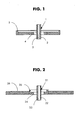
- FIG. 1 there is shown in section a current output terminal 1 of the type "glass-to-metal crossing" (TVM).
- the terminal is composed of a hollow central pin 2 comprising an internal channel 3 serving as a passage for the introduction of the electrolyte during filling.
- the central tubular pin 2 is surrounded by an annular gasket 4 made of glass which serves as the connection with the cover 5 of the accumulator.
- the cover 5 is metallic and can be used as a terminal for the opposite polarity.
- FIG. 2 represents a variant 21 of the same type of terminal, but intended to be used for generators of larger dimensions.
- the terminal comprises a central pin 22 , provided with an internal channel 23 for the passage of the electrolyte, and surrounded by a glass seal 24 .
- This seal is connected to a metal cup 25 which can for example be welded to the cover b of a generator.
- FIGS. 3 and 4 show an electrical connection according to the prior art between a connection 31 connected to the electrochemical bundle 32 and a terminal 33 for current output inserted in the cover 34 of a generator 35.
- the connection 31 must have a sufficient length to be able to be placed on the lateral surface 36 of the pin 37 of the terminal 33 .
- the connection 31 is then welded to the lateral surface 36 of the pin 37 between a fixed electrode 38 and a mobile electrode 39 .
- the cover 34 is then folded down to close the generator 35.
- Figure 4 is a sectional view of the generator 35 once the cover 34 is closed. We see the pin 37 surrounded by a glass gasket 40 which connects it to the cover 34.
- connection 31 When closing, the connection 31 takes the form of a flattened "S" so as to be able to be housed between the electrochemical bundle 32 and the cover 34 by passing under the base of the pin 37 at the risk of preventing the passage of the electrolyte.
- the electrical insulation between the cover 34 and the connection 31 is provided by an upper insulating washer 41.
- An insulating washer 42 in the form of a cup is necessary to ensure the insulation between the connection 31 and the electrochemical bundle 32 .
- a nail 43 is inserted into the internal channel 44 of the pin 37 and its upper end 45 is welded to seal the generator 35 .
- FIGS. 5 to 7 show an electrical connection according to the invention between a connection 50 connected to the electrochemical bundle 51 and a terminal 52 of current output inserted in the cover 53 of a generator 54.
- the connection 50 has a length much less than the connection 31 of Figure 3. This length is however sufficient to allow it to be placed on the transverse surface 55 of the pin 56 surrounded by a glass gasket 57 forming the terminal 52.
- the connection 50 is then welded to the end 55 of the pin 56 between a clamp serving as a fixed counter-electrode 58 and a mobile electrode 59 .
- a metal rod 60 is then introduced into the hollow internal part 61 of the pin 56 , as shown in FIG. 6, and a pressure in the direction of the arrows 62 is exerted on the rod 60 in order to create an orifice 63.
- the cover 53 is then folded down to close the generator 54.
- Figure 7 is a section of the generator 54 once the cover 53 is closed.
- the connection 50 takes the form of a "U" lying to be housed between the electrochemical bundle 51 and the cover 53.
- the shape adopted by connection 50 eliminates any risk vis-à-vis the obstruction of the electrolyte introduction channel.
- the electrical insulation between the cover 53 and the connection 50 is provided by an upper insulating washer 64 .
- a flat insulating washer 65 is sufficient to provide insulation between the connection 50 and the electrochemical bundle 51 . After introduction of the electrolyte a nail 66 is inserted into the inner channel 67 of the pin 56 and its upper end 68 is welded to ensure the sealing of the generator.
Landscapes
- Chemical & Material Sciences (AREA)
- Chemical Kinetics & Catalysis (AREA)
- Electrochemistry (AREA)
- General Chemical & Material Sciences (AREA)
- Inorganic Chemistry (AREA)
- Connection Of Batteries Or Terminals (AREA)
Abstract
Description
Le boítier du générateur porte des orifices accueillant des dispositifs permettant de mettre en relation le faisceau électrochimique et son environnement avec l'extérieur, comme des bornes d'entrée et de sortie du courant et un dispositif de sécurité en cas de surpression interne. Le boítier peut porter également un orifice traversant pour l'introduction d'un électrolyte liquide.
Les bornes d'un générateur électrochimique ont une double fonction: d'une part d'assurer la continuité électrique entre les électrodes du générateur électrochimique et l'application extérieure à laquelle il est associé, d'autre part de contribuer à l'étanchéité de la fermeture du générateur. La borne traverse la paroi du conteneur du générateur : la partie située à l'extérieur du conteneur reçoit les connexions provenant de l'application, la partie située à l'intérieur est reliée aux électrodes. Cette borne peut être solidaire ou rapportée au conteneur. Lorsqu'elle est rapportée au conteneur, un joint d'étanchéité et d'isolation électrique est usuellement prévu entre la sortie de courant et le conteneur du générateur. Les bornes du type dit "traversée verre-métal" (TVM) sont constituée d'un pion central métallique, qui assure la continuité électrique, entouré d'un joint en verre relié de manière étanche d'une part au pion central et d'autre part à la paroi du conteneur, par exemple le couvercle, dans laquelle la borne est insérée. Ces bornes TVM sont généralement de petite taille, et le pion central a un diamètre inférieur à sa longueur. A titre d'exemple son diamètre est compris entre 1,5 et 2mm et sa longueur est comprise entre 5 et 8mm, le diamètre de la borne étant compris entre 10 et 17mm.
Il existe plusieurs façons de raccorder électriquement une électrode à une borne de sortie de courant. L'une de ces façons est l'utilisation d'une lamelle conductrice ou mince bande métallique dont une extrémité est soudée sur le bord du collecteur de l'électrode et l'autre extrémité est soudée à la partie de la borne située à l'intérieur du conteneur. En pratique, pour connecter une électrode à une sortie de courant, par exemple à une borne qui traverse un couvercle, l'extrémité de la lamelle est positionnée, maintenue et fixée sur la partie interne de la borne. Le générateur est ensuite fermé à l'aide du couvercle.
Dans ce mode de réalisation, le positionnement de la lamelle vis-à-vis de la partie interne de la borne ainsi que son maintien avant sa fixation s'avère mal aisé. La fermeture du couvercle engendre ensuite un pliage complexe de la connexion. Au cours de cette opération, la fixation de la lamelle sur la borne, voire la lamelle elle-même, risque d'être détériorée. Les risques qui en découlent sont d'une part la survenue de courts-circuits et d'autre part l'obturation de la partie inférieure de l'orifice de remplissage en électrolyte.
Ainsi la hauteur totale du pion, donc l'encombrement du système, peut être réduite par rapport à un système dans lequel la connexion serait fixée sur une surface latérale du pion.
De préférence la connexion est soudée sur le pion afin d'assurer un contact électrique fiable. En outre on constate que la tenue à l'arrachement d'une telle fixation est de beaucoup supérieure à celle observée pour une connexion soudée sur la surface latérale du pion.
Dans ce cas la longueur de la connexion, nécessaire à la mise en place du raccordement, est moindre que dans les générateurs connus. Une longueur plus courte facilite le positionnement de la connexion à l'intérieur du générateur lors de sa fermeture. On évite ainsi les courts-circuits. En outre le risque d'obstruction du canal interne du pion est éliminé du fait de la présence d'un orifice dans la connexion et du maintien en place de cet orifice par rapport au pion.
De préférence ladite borne de sortie de courant est constituée d'au moins un pion central conducteur tubulaire entouré d'un joint annulaire en verre.
La connexion est d'abord placée sur une extrémité transversale du pion qui est maintenu à l'aide d'une pince. La position de la connexion sur la borne présente l'avantage de préserver la visibilité de l'emplacement où s'effectue la fixation pendant toute la durée de l'opération.
Avantageusement on soude la connexion sur le pion de manière à assurer une fixation fiable. De préférence on soude électriquement la connexion sur le pion. Dans ce cas la pince peut constituer une première électrode de soudure dont la position reste fixe au cours de l'opération de soudure, et la connexion est soudée électriquement sur le pion à l'aide d'une seconde électrode de soudure déplaçable pour venir se placer précisément en position de soudure.
Enfin on perce ladite connexion à l'aide d'un outil introduit à l'intérieur dudit pion afin de réaliser un orifice. Avantageusement cet orifice est obtenu par découpe et enfoncement de matière afin d'obtenir un crevé. Ainsi le perçage ne produit pas de copeaux, ni de poussières métalliques susceptibles de rester à l'intérieur du générateur et de provoquer des courts-circuits. En outre le perçage de la connexion après fixation de celle-ci sur le pion garanti l'alignement de l'intérieur du tube et de l'orifice réalisé.
- on maintient ledit pion à l'aide d'une pince constituant une première électrode de soudure, dont le position est de préférence fixe,
- on place ladite connexion sur l'extrémité transversale interne dudit pion,
- on soude électriquement ladite connexion sur ladite extrémité à l'aide d'une seconde électrode, de préférence mobile pour être amenée en position de soudure,
- on perce ladite connexion à l'aide d'un outil introduit à l'intérieur dudit pion de manière à réaliser un orifice par découpe et enfoncement de matière.
- la figure 1 est une vue en coupe d'une borne de sortie de courant du type "traversée verre-métal" (TVM) dont le pion central comprend un canal intérieur pour l'introduction d'un électrolyte liquide,
- la figure 2 est une vue en coupe du couvercle d'un générateur électrochimique comportant une borne de sortie de courant du type TVM dont le pion central comprend un canal intérieur pour l'introduction d'un électrolyte liquide,
- la figure 3 montre l'opération de raccordement électriquement d'une connexion d'électrode à une borne TVM selon l'art antérieur,
- la figure 4 représente une vue partielle en coupe d'un générateur électrochimique dans lequel l'électrode est raccordée électriquement à une borne TVM selon l'art antérieur,
- la figure 5 montre l'opération de raccordement électriquement d'une connexion d'électrode à une borne TVM selon la présente invention,
- la figure 6 montre l'opération de perçage de la connexion après fixation sur le pion,
- la figure 7 représente une vue partielle en coupe d'un générateur électrochimique dans lequel l'électrode est raccordée électriquement à une borne TVM selon la présente invention.
On voit sur la figure 3 que la connexion 31 doit avoir une longueur suffisante pour pouvoir être placée sur la surface latérale 36 du pion 37 de la borne 33. La connexion 31 est alors soudée sur la surface latérale 36 du pion 37 entre une électrode fixe 38 et une électrode mobile 39. Le couvercle 34 est ensuite rabattu pour fermer le générateur 35.
La figure 4 est une vue en coupe du générateur 35 une fois le couvercle 34 refermé. On y voit le pion 37 entouré d'un joint de verre 40 qui le relie au couvercle 34. Lors de la fermeture, la connexion 31 prend une forme de "S" aplati afin de pouvoir se loger entre le faisceau électrochimique 32 et le couvercle 34 en passant sous la base du pion 37 au risque d'empêcher le passage de l'électrolyte. L'isolation électrique entre le couvercle 34 et la connexion 31 est assurée par une rondelle isolante supérieure 41. Une rondelle isolante 42 en forme de coupelle est nécessaire pour assurer l'isolation entre la connexion 31 et le faisceau électrochimique 32. Après introduction de l'électrolyte un clou 43 est insérée dans le canal intérieur 44 du pion 37 et son extrémité supérieure 45 est soudée pour assurer l'étanchéité du générateur 35.
On voit sur la figure 5 que la connexion 50 a une longueur très inférieure à la connexion 31 de la figure 3. Cette longueur est cependant suffisante pour lui permettre de se placer sur la surface transversale 55 du pion 56 entouré d'un joint de verre 57 formant la borne 52. La connexion 50 est alors soudée sur l'extrémité 55 du pion 56 entre une pince servant de contre-électrode fixe 58 et une électrode mobile 59.
La figure 7 est une coupe du générateur 54 une fois le couvercle 53 refermé. On y voit le pion 56 entouré du joint de verre 57 qui le relie au couvercle 53. Lors de fermeture, la connexion 50 prend une forme de "U" couché pour se loger entre le faisceau électrochimique 51 et le couvercle 53. La forme adoptée par la connexion 50 écarte tout risque vis-à-vis de l'obstruction du canal d'introduction de l'électrolyte. L'isolation électrique entre le couvercle 53 et la connexion 50 est assurée par une rondelle isolante supérieure 64. Une rondelle isolante 65 plane suffit à assurer l'isolation entre la connexion 50 et le faisceau électrochimique 51. Après introduction de l'électrolyte un clou 66 est inséré dans le canal intérieur 67 du pion 56 et son extrémité supérieure 68 est soudée pour assurer l'étanchéité du générateur.
Claims (14)
- Système de raccordement électrique d'une connexion plane sur une borne de sortie de courant comprenant un pion conducteur tubulaire, caractérisé en ce que ladite connexion comporte un orifice et en ce que ladite connexion est fixée sur une section transversale dudit pion de manière à faire communiquer ledit orifice avec l'intérieur dudit tube.
- Système selon la revendication 1, dans lequel ladite connexion est soudée sur ledit pion.
- Générateur incluant un système de raccordement selon l'une des revendications 1 et 2, comportant une connexion plane reliée électriquement à une des électrodes et une borne de sortie de courant comprenant un pion central conducteur entouré d'un joint annulaire en verre, ledit pion ayant la forme d'un tube dont une extrémité s'ouvre vers l'extérieur et l'autre extrémité s'ouvre vers l'intérieur dudit générateur, caractérisé en ce que ladite connexion comporte un orifice et est soudée sur la face transversale interne dudit pion de manière à faire coïncider ledit orifice avec l'intérieur dudit pion.
- Générateur selon la revendication 3, dans lequel ladite borne de sortie de courant est constituée d'au moins un pion central conducteur tubulaire entouré d'un joint annulaire en verre.
- Générateur selon l'une des revendications 3 et 4, dans lequel le diamètre intérieur de dudit orifice est moindre que le diamètre intérieur dudit pion.
- Procédé de réalisation d'un système de raccordement selon l'une des revendications 1 et 2, comportant une connexion plane et une borne de sortie de courant comprenant un pion conducteur tubulaire, ledit procédé comprenant les étapes suivantes :on place ladite connexion sur une extrémité transversale dudit pion,on fixe ladite connexion sur ladite extrémité,on perce ladite connexion.
- Procédé selon la revendication 6, dans lequel ledit pion est maintenu à l'aide d'une pince.
- Procédé selon l'une des revendications 6 et 7, dans lequel on soude ladite connexion sur ledit pion.
- Procédé selon l'une des revendications 6 à 8, dans lequel on soude électriquement ladite connexion sur ledit pion.
- Procédé selon la revendication 9, dans lequel ladite pince constitue une première électrode de soudure.
- Procédé selon l'une des revendications 9 et 10, dans lequel ladite connexion est soudée électriquement sur ledit pion à l'aide d'une seconde électrode de soudure.
- Procédé selon lune des revendications 6 à 11, dans lequel on perce ladite connexion à l'aide d'un outil introduit à l'intérieur dudit pion.
- Procédé selon lune des revendications 6 à 12, dans lequel on réalise un orifice dans ladite connexion par découpe et enfoncement de matière.
- Procédé de fabrication d'un générateur électrochimique selon l'une des revendications 3 à 5 comportant une connexion plane et une borne de sortie de courant comprenant un pion conducteur tubulaire, ledit procédé comprenant les étapes suivantes :on maintient ledit pion à l'aide d'une pince constituant une première électrode de soudure,on place ladite connexion sur l'extrémité transversale interne dudit pion,on soude électriquement ladite connexion sur ladite extrémité à l'aide d'une seconde électrode,on perce ladite connexion à l'aide d'un outil introduit à l'intérieur dudit pion de manière à réaliser un orifice par découpe et enfoncement de matière.
Applications Claiming Priority (2)
| Application Number | Priority Date | Filing Date | Title |
|---|---|---|---|
| FR0304260A FR2853455B1 (fr) | 2003-04-04 | 2003-04-04 | Raccordement electrique d'une connexion sur une borne |
| FR0304260 | 2003-04-04 |
Publications (2)
| Publication Number | Publication Date |
|---|---|
| EP1465266A1 true EP1465266A1 (fr) | 2004-10-06 |
| EP1465266B1 EP1465266B1 (fr) | 2006-04-19 |
Family
ID=32843150
Family Applications (1)
| Application Number | Title | Priority Date | Filing Date |
|---|---|---|---|
| EP04290874A Expired - Lifetime EP1465266B1 (fr) | 2003-04-04 | 2004-04-02 | Raccordement électrique d'une connexion sur une borne |
Country Status (4)
| Country | Link |
|---|---|
| US (2) | US7335443B2 (fr) |
| EP (1) | EP1465266B1 (fr) |
| DE (1) | DE602004000662T2 (fr) |
| FR (1) | FR2853455B1 (fr) |
Families Citing this family (3)
| Publication number | Priority date | Publication date | Assignee | Title |
|---|---|---|---|---|
| US10224521B2 (en) | 2011-02-18 | 2019-03-05 | Schott Ag | Feed-through |
| US11462789B2 (en) | 2011-02-18 | 2022-10-04 | Schott Ag | Base body for feeding through of a conductor, and a housing component of a housing, in particular a battery housing comprising said base body |
| KR101981811B1 (ko) | 2011-02-18 | 2019-05-23 | 쇼오트 아게 | 특히 배터리용 피드스루 및 초음파 용접에 의해 하우징에 피드스루를 통합하는 방법 |
Citations (6)
| Publication number | Priority date | Publication date | Assignee | Title |
|---|---|---|---|---|
| US4042756A (en) * | 1976-04-12 | 1977-08-16 | Gte Laboratories Incorporated | Electrochemical cells |
| US4347293A (en) * | 1980-04-29 | 1982-08-31 | Gte Products Corporation | Electrochemical cell |
| FR2513806A1 (fr) * | 1981-09-25 | 1983-04-01 | Europ Composants Electron | Condensateurs electrolytiques munis d'une traversee metal/verre a etancheite renforcee |
| EP0118657A1 (fr) * | 1983-01-14 | 1984-09-19 | Kabushiki Kaisha Toshiba | Cellule électrochimique non aqueuse |
| FR2585185A1 (fr) * | 1985-07-16 | 1987-01-23 | Accumulateurs Fixes | Capot metallique pour piles electriques et piles electriques en faisant application |
| JPH09153368A (ja) * | 1995-11-30 | 1997-06-10 | Sanyo Electric Co Ltd | 非水電解液リチウム電池およびその製造方法 |
Family Cites Families (1)
| Publication number | Priority date | Publication date | Assignee | Title |
|---|---|---|---|---|
| US6670074B2 (en) * | 2001-04-23 | 2003-12-30 | Wilson Greatbatch Ltd. | Glass to metal seal |
-
2003
- 2003-04-04 FR FR0304260A patent/FR2853455B1/fr not_active Expired - Fee Related
-
2004
- 2004-04-02 EP EP04290874A patent/EP1465266B1/fr not_active Expired - Lifetime
- 2004-04-02 DE DE602004000662T patent/DE602004000662T2/de not_active Expired - Lifetime
- 2004-04-02 US US10/815,685 patent/US7335443B2/en not_active Expired - Fee Related
-
2007
- 2007-12-17 US US12/000,711 patent/US20080092368A1/en not_active Abandoned
Patent Citations (6)
| Publication number | Priority date | Publication date | Assignee | Title |
|---|---|---|---|---|
| US4042756A (en) * | 1976-04-12 | 1977-08-16 | Gte Laboratories Incorporated | Electrochemical cells |
| US4347293A (en) * | 1980-04-29 | 1982-08-31 | Gte Products Corporation | Electrochemical cell |
| FR2513806A1 (fr) * | 1981-09-25 | 1983-04-01 | Europ Composants Electron | Condensateurs electrolytiques munis d'une traversee metal/verre a etancheite renforcee |
| EP0118657A1 (fr) * | 1983-01-14 | 1984-09-19 | Kabushiki Kaisha Toshiba | Cellule électrochimique non aqueuse |
| FR2585185A1 (fr) * | 1985-07-16 | 1987-01-23 | Accumulateurs Fixes | Capot metallique pour piles electriques et piles electriques en faisant application |
| JPH09153368A (ja) * | 1995-11-30 | 1997-06-10 | Sanyo Electric Co Ltd | 非水電解液リチウム電池およびその製造方法 |
Also Published As
| Publication number | Publication date |
|---|---|
| FR2853455A1 (fr) | 2004-10-08 |
| FR2853455B1 (fr) | 2005-06-17 |
| US7335443B2 (en) | 2008-02-26 |
| US20080092368A1 (en) | 2008-04-24 |
| US20040219425A1 (en) | 2004-11-04 |
| DE602004000662D1 (de) | 2006-05-24 |
| EP1465266B1 (fr) | 2006-04-19 |
| DE602004000662T2 (de) | 2007-04-05 |
Similar Documents
| Publication | Publication Date | Title |
|---|---|---|
| EP1596449B1 (fr) | Raccordement électrique à un faisceau de connexion pour électrodes | |
| EP0822605B1 (fr) | Générateur électrochimique cylindrique à électrodes enroulées en spirale | |
| EP0003133B1 (fr) | Dispositif de traversée étanche d'une paroi simple ou double en matière plastique par une connexion électrique et application à une batterie de générateurs électrochimiques | |
| EP1221728B1 (fr) | Soupape refermable et générateur électrochimique comprenant une telle soupape | |
| FR3004368A1 (fr) | Brasage sans outillage | |
| FR2947960A1 (fr) | Dispositif de connexion a sertir pour cable electrique et procede de fabrication d'un tel dispositif | |
| EP2938512B1 (fr) | Detection d'avarie d'une bande de captage | |
| EP1465266B1 (fr) | Raccordement électrique d'une connexion sur une borne | |
| CA1038446A (fr) | Generateur electrochimique a boitier etanche | |
| EP3035411B1 (fr) | Procede de connexion dans un accumulateur et accumulateur ainsi connecte | |
| FR2614750A1 (fr) | Electrode tubulaire pour torche a plasma et torche a plasma pourvue de telles electrodes | |
| CA2847105C (fr) | Ensemble de stockage d'energie longue duree a piece de connexion intermediaire | |
| BE897625A (fr) | Perfectionnements aux piles electrochimiques | |
| EP2812936A1 (fr) | Couvercle pour ensemble de stockage d'energie, ensemble de stockage d'energie comportant ledit couvercle, et procede de fabrication d'un tel ensemble de stockage d'energie | |
| FR2752092A1 (fr) | Generateur electrochimique a electrodes spiralees | |
| EP3316350B1 (fr) | Piece de connexion electrique pour accumulateur | |
| FR2983648A1 (fr) | Contact de connecteur electrique pour la connexion a un fil d'un composant electronique | |
| EP0867961A1 (fr) | Générateur électrochimique à bobineau spiralé | |
| EP2239802A1 (fr) | Accumulateur et procede de fabrication | |
| FR2942079A1 (fr) | Borne de sortie de courant pour accumulateur. | |
| EP4602677B1 (fr) | Cellule électrique et son procédé de fabrication | |
| FR2860103A1 (fr) | Procede de raccordement electrique d'une connexion sur une sortie de courant | |
| JP2006019220A (ja) | 電池 | |
| EP4095878A1 (fr) | Dispositif de coupure d'un appareil électrique | |
| EP1861650A1 (fr) | Cartouche pour fluide sous pression |
Legal Events
| Date | Code | Title | Description |
|---|---|---|---|
| PUAI | Public reference made under article 153(3) epc to a published international application that has entered the european phase |
Free format text: ORIGINAL CODE: 0009012 |
|
| AK | Designated contracting states |
Kind code of ref document: A1 Designated state(s): AT BE BG CH CY CZ DE DK EE ES FI FR GB GR HU IE IT LI LU MC NL PL PT RO SE SI SK TR |
|
| AX | Request for extension of the european patent |
Extension state: AL HR LT LV MK |
|
| 17P | Request for examination filed |
Effective date: 20050406 |
|
| 17Q | First examination report despatched |
Effective date: 20050512 |
|
| AKX | Designation fees paid |
Designated state(s): DE FR GB |
|
| GRAP | Despatch of communication of intention to grant a patent |
Free format text: ORIGINAL CODE: EPIDOSNIGR1 |
|
| GRAS | Grant fee paid |
Free format text: ORIGINAL CODE: EPIDOSNIGR3 |
|
| GRAA | (expected) grant |
Free format text: ORIGINAL CODE: 0009210 |
|
| AK | Designated contracting states |
Kind code of ref document: B1 Designated state(s): DE FR GB |
|
| REG | Reference to a national code |
Ref country code: GB Ref legal event code: FG4D Free format text: NOT ENGLISH |
|
| REF | Corresponds to: |
Ref document number: 602004000662 Country of ref document: DE Date of ref document: 20060524 Kind code of ref document: P |
|
| GBT | Gb: translation of ep patent filed (gb section 77(6)(a)/1977) |
Effective date: 20060517 |
|
| PLBE | No opposition filed within time limit |
Free format text: ORIGINAL CODE: 0009261 |
|
| STAA | Information on the status of an ep patent application or granted ep patent |
Free format text: STATUS: NO OPPOSITION FILED WITHIN TIME LIMIT |
|
| 26N | No opposition filed |
Effective date: 20070122 |
|
| REG | Reference to a national code |
Ref country code: FR Ref legal event code: PLFP Year of fee payment: 13 |
|
| REG | Reference to a national code |
Ref country code: FR Ref legal event code: PLFP Year of fee payment: 14 |
|
| PGFP | Annual fee paid to national office [announced via postgrant information from national office to epo] |
Ref country code: FR Payment date: 20170407 Year of fee payment: 14 Ref country code: DE Payment date: 20170411 Year of fee payment: 14 Ref country code: GB Payment date: 20170412 Year of fee payment: 14 |
|
| REG | Reference to a national code |
Ref country code: DE Ref legal event code: R119 Ref document number: 602004000662 Country of ref document: DE |
|
| GBPC | Gb: european patent ceased through non-payment of renewal fee |
Effective date: 20180402 |
|
| PG25 | Lapsed in a contracting state [announced via postgrant information from national office to epo] |
Ref country code: DE Free format text: LAPSE BECAUSE OF NON-PAYMENT OF DUE FEES Effective date: 20181101 |
|
| PG25 | Lapsed in a contracting state [announced via postgrant information from national office to epo] |
Ref country code: GB Free format text: LAPSE BECAUSE OF NON-PAYMENT OF DUE FEES Effective date: 20180402 |
|
| PG25 | Lapsed in a contracting state [announced via postgrant information from national office to epo] |
Ref country code: FR Free format text: LAPSE BECAUSE OF NON-PAYMENT OF DUE FEES Effective date: 20180430 |