The present invention relates to an information
storage medium such as an optical disk formed with a
wobbled track. The present invention also relates to
an information storage medium evaluation method and
information storage medium evaluation apparatus, which
evaluate the quality of such information storage
medium. The present invention relates to an
information reproduction apparatus and information
reproduction method, which reproduce information from
such information storage medium. Furthermore, the
present invention relates to an information recording
apparatus for recording information on such information
storage medium.
As is well known, in recent years, optical disks
having a single-layer/single-sided size of 4.7 GB are
commercially available as those which can achieve
high-density recording of information. For example, a
DVD-ROM as a read-only optical disk, and a rewritable
DVD+RW (ECMA-337), DVD-RW (ECMA-338), and DVD-RAM
(ECMA-330) are available.
An information recording layer is formed on a
transparent substrate on each of these optical disks.
An information recording layer of such optical disk has
a guide groove called a "groove". Recording/reproduction
of information on/from an optical disk is
made along this guide groove. By focusing a laser beam
on the guide groove of the information recording layer,
information is recorded on this guide groove or
information recorded on that guide groove is
reproduced.
For example, physical addresses used to specify a
spatial position where information is to be recorded/reproduced
are recorded on the DVD-RAM. For example,
these physical addresses are formed to obstruct the
guide groove.
By contrast, on a +RW disk, physical addresses are
reflected on the guide groove using groove wobble
modulation (to be referred to as wobble modulation
hereinafter) that radially slightly wobbles the guide
groove. This method changes the wobble phase in
correspondence with information to be recorded
(physical address), and its technique is disclosed in,
e.g., Jpn. Pat. Appln. KOKAI Publication No. 10-283738.
Physical addresses which are recorded by such wobble
modulation do not obstruct the recording track.
That is, the physical addresses recorded by wobble
modulation do not limit the recording area of user
information on a disk. Hence, wobble modulation can
assure high format efficiency, and can easily achieve
compatibility to read-only media.
As an evaluation measure of the quality of a
wobble signal formed by optically reproducing the
groove wobbles, the Narrow Band Signal to Noise Ratio
(NBSNR) of the wobble signal is known. This value is
used to evaluate the ratio of the amplitude of a
carrier that carries the wobble signal to that of
noise, and indicates a higher demodulation ratio with
increasing NBSNR. This NBSNR is also called a Carrier
to Noise Ratio (CNR).
Normally, the NBSNR of a wobble signal is measured
by inputting a wobble signal to a frequency component
analysis device such as a spectrum analyzer or the
like, and calculating the difference between the peak
value of a carrier frequency and the noise level near
the carrier frequency. However, when the wobble signal
contains modulated components, the peak value of the
carrier frequency becomes lower than the actual one.
Also, the frequency of the modulated components raises
the signal level near the carrier frequency. Hence,
when the wobble signal contains modulated components,
the NBSNR of the wobble signal cannot be accurately
measured.
On the other hand, a wobble signal obtained from a
+RW disk contains two different components, i.e.,
non-modulated and modulated components, and most of
components are non-modulated components. For this
reason, the NBSNR of the wobble signal can be measured
by practically disregarding modulated components.
However, when a modulated region is reduced, an
information size that can be recorded becomes smaller.
Hence, when a recording capacity of information by
wobble modulation is increased, this method cannot be
used.
In order to maintain a high-quality wobbled track,
the NBSNR of a wobble signal must be accurately
measured. If the NBSNR of the wobble signal cannot be
accurately measured, the quality of a wobble track may
deteriorate. If a wobble track has poor quality,
physical address information reflected on the wobble
track cannot be normally reproduced. Hence, correct
information may not consequently reproduced from a
disk. Likewise, correct information may not be
recorded on a disk.
It is an object of the present invention to
provide an information storage medium evaluation method
and evaluation apparatus, which allow accurate
performance evaluation. It is another object of the
present invention to provide an information storage
medium formed with a high-quality wobbled track by
accurate performance evaluation of a wobble signal. It
is still another object of the present invention to
provide an information reproduction apparatus and
information reproduction method, which can reproduce
correct information from an information storage medium
formed with a high-quality wobbled track by accurate
performance evaluation of a wobble signal. It is still
another object of the present invention to provide an
information recording method which can record correct
information on an information storage medium formed
with a high-quality wobbled track by accurate
performance evaluation of a wobble signal.
According to embodiments of the present invention,
there is provided an information storage medium
evaluation method for evaluating an information storage
medium, which comprises a wobbled track that is used to
guide a light beam and is wobbled in correspondence
with a frequency, a phase of which is modulated at
predetermined timings to reflect predetermined
information, comprising squaring (double-multiplying) a
reproduction signal corresponding to the wobbled track,
obtained from reflected light of the light beam with
which the wobbled track is irradiated, and evaluating
quality of the wobbled track on the basis of frequency
characteristics of the squared (double-multiplied)
reproduction signal.
According to embodiments of the present invention,
there is provided an information storage medium
evaluation apparatus for evaluating an information
storage medium, which comprises a wobbled track that is
used to guide a light beam and is wobbled in
correspondence with a frequency, a phase of which is
modulated at predetermined timings to reflect
predetermined information, comprising a detection unit
configured to detect reflected light of a light beam
with which the wobbled track formed on the information
storage medium is irradiated, a filter unit configured
to suppress noise from a reproduction signal
corresponding to the wobbled track on the basis of the
reflected light detected by the detection unit, a
squaring unit configured to square the reproduction
signal from which the noise is suppressed by the filter
unit, and an evaluation unit configured to evaluate
quality of the wobbled track on the basis of frequency
characteristics of the squared reproduction signal
squared by the squaring unit.
According to embodiments of the present invention,
there is provided an information storage medium for
storing information, comprising an information storage
area for storing information, and a wobbled track which
is used to guide a light beam on the information
storage area, and is wobbled in correspondence with
a frequency, a phase of which is modulated at
predetermined timings to reflect predetermined
information, wherein the wobbled track is formed so
that when a reproduction signal corresponding to the
wobbled track obtained from reflected light of a light
beam, with which the wobbled track is irradiated, is
squared, and the squared reproduction signal is
evaluated on the basis of frequency characteristics of
the squared reproduction signal, a difference between
peak and noise levels obtained from the frequency
characteristics of the squared reproduction signal
becomes not less than 17 dB.
According to embodiments of the present invention,
there is provided an information reproduction apparatus
for reproducing information from an information storage
medium on which a wobbled track, which is wobbled at a
frequency, a phase of which is modulated at predetermined
timings to reflect predetermined information, is
formed, so that an evaluation result based on frequency
characteristics of a squared reproduction signal
obtained by squaring a reproduction signal
corresponding to the wobbled track, obtained from
reflected light of a light beam with which the wobbled
track is irradiated, meets a predetermined evaluation
measure, comprising a detection unit configured to
detect the reflected light of the light beam with which
the wobbled track formed on the information storage
medium is irradiated, and a reproduction unit
configured to reproduce the predetermined information
reflected on the wobbled track on the basis of the
reflected light detected by the detection unit.
According to embodiments of the present invention,
there is provided an information reproduction method
for reproducing information from an information storage
medium on which a wobbled track, which is wobbled at a
frequency, a phase of which is modulated at predetermined
timings to reflect predetermined information, is
formed, so that an evaluation result based on frequency
characteristics of a squared reproduction signal
obtained by squaring a reproduction signal
corresponding to the wobbled track, obtained from
reflected light of a light beam with which the wobbled
track is irradiated, meets a predetermined evaluation
measure, comprising detecting the reflected light of
the light beam with which the wobbled track formed on
the information storage medium is irradiated, and
reproducing the predetermined information reflected on
the wobbled track on the basis of the detected
reflected light.
According to embodiments of the present invention,
there is provided an information recording method for
recording information on an information storage medium
on which a wobbled track, which is wobbled at a
frequency, a phase of which is modulated at predetermined
timings to reflect predetermined information, is
formed, so that an evaluation result based on frequency
characteristics of a squared reproduction signal
obtained by squaring a reproduction signal
corresponding to the wobbled track, obtained from
reflected light of a light beam with which the wobbled
track is irradiated, meets a predetermined evaluation
measure, comprising detecting the reflected light of
the light beam with which the wobbled track formed on
the information storage medium is irradiated,
reproducing the predetermined information reflected
on the wobbled track on the basis of the detected
reflected light, and recording information on the
information storage medium on the basis of the
reproduced predetermined information.
This summary of the invention does not necessarily
describe all necessary features so that the invention
may also be a sub-combination of these described
features.
The invention can be more fully understood from
the following detailed description when taken in
conjunction with the accompanying drawings, in which:
A preferred embodiment of the present invention
will be described hereinafter with reference to the
accompanying drawings.
FIG. 1 is a schematic block diagram showing the
arrangement of an optical disk apparatus according to
an embodiment of the present invention. The optical
disk apparatus shown in FIG. 1 serves as an information
reproduction apparatus and also an information
recording apparatus. That is, this optical disk
apparatus records recording data on an optical disk D1
and reproduces recording data recorded on the optical
disk D1.
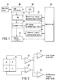
As shown in FIG. 1, the optical disk apparatus
comprises a controller 10, recording signal processing
circuit 20, laser driver (LDD) 30, pickup head (PUH)
40, photodetector (PD) 50, preamplifier 60, servo
circuit 70, RF signal processing circuit 80, address
signal processing unit 90, and the like.
This optical disk apparatus records/reproduces
information by focusing a laser beam emitted by the PUH
40 on an information recording layer of the optical
disk D1. Light reflected by optical disk D1 passes
through an optical system of the PUH 40, and is
detected as an electrical signal by the PD 50.
The PD 50 has two or more photodetection elements.
A signal obtained by summing of a plurality of
electrical signals detected by respective elements is
called a sum signal, and a signal obtained by
subtraction of a plurality of electrical signals
detected by respective elements is called a difference
signal. Especially, a sum signal appended with
high-frequency information such as user information or
the like is called an RF signal. Also, a signal
obtained by subtraction of signals obtained from
respective elements which are optically arranged in the
radial direction of the optical disk is called a radial
push-pull signal.
FIG. 2 shows an example of a 4-split PD. As shown
in FIG. 2, the PD 50 comprises 4-split photodetection
elements 51, adders 52, 53, and 54, and a subtractor
55. Two out of four signals detected by the photodetection
elements 51 are added by the adder 52, and
the remaining two signals are added by the adder 53.
The adder 54 adds the sum signals output from the
adders 52 and 53 to generate a sum signal. That is,
the sum signal is obtained by adding all four signals
detected by the photodetection elements 51. On the
other hand, the subtractor 55 subtracts the sum signal
output from the adder 53 from that output from the
adder 52 to generate a difference signal. This
difference signal is a radial push-pull signal.
The electrical signals detected by the PD 50 are
amplified by the preamplifier 60, and are sent to the
servo circuit 70, RF signal processing circuit 80, and
address signal processing unit 90.
The servo circuit 70 generates focusing, tracking,
and tilt servo signals and the like on the basis of the
electrical signals detected by the PD 50, and outputs
these servo signals to focusing, tracking, and tilt
actuators of the PUH 40.
The RF signal processing circuit 80 mainly
processes the sum signal of the electrical signals
detected by the PD 50 to reproduce recorded user
information and the like. As a demodulation method in
this case, a slice method or PRML (Partial Response
Maximum Likelihood) method may be used.
The address signal processing unit 90 reads out
physical address information indicating a recording
position on the optical disk by processing the
electrical signals detected by the PD 50, and outputs
that information to the controller 10. The controller
10 reads out user information or the like at a desired
position, or records user information or the like at
a desired position on the basis of this address
information. In this case, user information is
modulated to a signal suited for optical disk recording
by the recording signal processing circuit 20. For
example, modulation rules such as (1, 10)RLL,
(2, 10)RLL, and the like are applied. RLL is an
abbreviation for run length limitation, and (1, 10)RLL
is a rule for limiting the upper limit of the runlength
of channel bits "0" to 10, and the lower limit of the
runlength to 1. That is, on a disk which is recorded
under the condition of (1, 10)RLL, channel bits "0"
successively appear within the runlength range of 1 to
10. Likewise, on a disk which is recorded under the
condition of (2, 10)RLL, channel bits "0" successively
appear within the runlength range of 2 to 10.
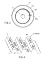
The optical disk D1 according to an embodiment
of the present invention comprises a transparent
substrate, and an information recording layer stacked
on this transparent substrate. As shown in FIG. 3, the
optical disk D1 (information recording layer) includes
an information recording area D12, which includes a
guide groove (track D13) called a groove. The guide
groove is called a track, and information recording/reproduction
is made along this track. The track
includes a spiral track D13 which continues from the
inner periphery to the outer periphery of the disk, as
shown in FIG. 3, and concentric tracks formed of a
plurality of concentric circles.
FIG. 4 shows a locally enlarged portion D13a of
the track D13 shown in FIG. 3. As shown in FIG. 4, the
track D13 is formed by concave and convex portions of
the information recording layer. The concave portion
is called a groove (groove track GT), and the convex
portion is called a land (land track LT). As a
recording method, a land-groove method, and groove
(land) only method are available. FIG. 4 shows an
example of the land-groove method. As shown in FIG. 4,
the land-groove method records information (recording
marks RM) on both the land track LT and groove track
GT. By contrast, the groove (land) only recording
method records information only on either type of
track. The present invention can be applied to both
the methods.
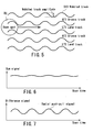
FIG. 5 is a top view of the track formed on the
optical disk. As shown in FIG. 5, groove and land
tracks GT and LT are alternately formed. That is, a
land track LT1 is formed between groove tracks GT1 and
GT2, and a groove track GT2 is formed between land
tracks LT1 and LT2.
The track (groove and land tracks GT and LT)
formed on the optical disk of the present invention
slightly wobbles in the radial direction. Such track
is called a wobbled track D13. By scanning a focused
beam spot BS along this wobbled track D13, the beam
spot goes nearly straight along the center of the
wobbled track since the frequency of wobbles is higher
than the frequency band of a tracking servo signal. At
this time, the sum signal remains nearly unchanged, as
shown in FIG. 6. By contrast, the difference signal in
the radial direction, i.e., only the radial push-pull
signal changes in correspondence with wobbles, as shown
in FIG. 7. This signal is called a wobble signal. The
wobble signal is used in adjustment of the rotation
frequency of a spindle, reference of recording clocks,
recording of physical address information, and the
like.
The optical disk of the present invention is
formed with the wobbled track, which is wobbled in
correspondence with a frequency, the phase of which
is modulated at predetermined timings to reflect
management information such as physical address
information and the like. That is, management
information such as physical address information and
the like can be reproduced from a wobble signal
obtained in correspondence with the wobbled track
formed on the optical disk. For example, a wobbled
track, which is wobbled in correspondence with a
phase-modulated frequency, shown in FIG. 8 or 9, is
formed. FIG. 8 shows an example in which the
phase-modulated frequency is reflected over the entire
track. FIG. 9 shows an example in which the
phase-modulated frequency is reflected on given
portions of the track, and a non-phase-modulated
frequency is reflected on other portions. In either
case, the address information processing unit 90 can
read management information such as physical address
information and the like reflected on the track. As
shown in FIG. 10, the address information processing
unit 90 comprises a band-pass filter 91, wobble PLL 92,
symbol clock generator 93, phase comparator 94,
low-pass filter 95, binarizer 96, and address
information processing circuit 97. The address
information processing unit 90 reads management
information such as physical address information and
the like reflected on the wobbled track from the radial
push-pull signal supplied from the PD 50.
FIG. 11 shows the frequency characteristics of a
non-modulated, single-frequency wobble signal. The
frequency characteristics have a peak at a carrier
frequency (f1) of the wobble signal, and other portions
correspond to noise components. As shown in FIG. 11,
the NBSNR (or CNR) can be measured by calculating the
difference between the peak value and noise level.
FIG. 12 shows the frequency characteristics of a
binary phase-modulated wobble signal in which the phase
difference between symbols is about 180°. The
frequency characteristics rise in the vicinity of a
carrier frequency (f2), but peaks are generated on the
two sides of the carrier frequency and their peripheral
portions of these peaks are also raised due to the
influence of modulated components. Therefore, the
NBSNR of the wobble signal cannot be measured unlike in
FIG. 11.
FIG. 13 shows the frequency characteristics of
a wobble signal which includes modulated and
non-modulated regions at a ratio of 1 : 4. Since a
long non-modulated region appears, the frequency
characteristics have a peak at a carrier frequency
(f3), but the peak value is reduced and its peripheral
portions are raised due to the influence of modulated
components. Therefore, in this case, the NBSNR of the
wobble signal cannot be accurately measured as in
FIG. 12.
In order to accurately measure the NBSNR of the
wobble signal, the present invention defines a NBSNR of
squared wobble signal. This NBSNR of squared wobble
signal indicates the difference between the noise level
and a peak value which appears at a frequency twice the
wobble carrier frequency from the frequency characteristics
of the squared result of the wobble signal.
FIG. 14 shows the frequency characteristics of
a squared wobble signal obtained by squaring a
non-modulated, single-frequency wobble signal. FIG. 15
shows the frequency characteristics of a squared wobble
signal obtained by squaring a binary phase-modulated
wobble signal in which the phase difference between
symbols is about 180°. FIG. 16 shows the frequency
characteristics of a squared wobble signal obtained by
squaring a locally modulated wobble signal. As can be
seen from FIGS. 14, 15, and 16, each squared wobble
signal has simple frequency characteristics which have
only one peak at 2 × f1, 2 × f2, or 2 × f3. This is to
extract only a carrier component of the wobble signal
by squaring the wobble signal. Therefore, when the
difference between the noise level and a peak value
which appears at a frequency twice the carrier
frequency in the squared frequency characteristics is
calculated as the NBSNR of squared wobble signal, and
that NBSNR of squared wobble signal is evaluated,
accurate performance of the wobble signal can be
recognized. Also, since this NBSNR of squared wobble
signal assumes a value obtained by subtracting about 6
dB from the NBSNR of the wobble signal before squaring,
the NBSNR can be estimated by adding 6 dB to the
measured NBSNR of squared wobble signal. However, when
the NBSNR of squared wobble signal is measured using a
circuit, a difference of around 7 dB appears due to the
influence of noise and the like.
In addition, the NBSNR of squared wobble signal
allows performance evaluation of the wobble signal in
more detail than the normal NBSNR. Normally, in the
performance evaluation of a modulated wobble signal,
the phase difference between symbols must be evaluated
in addition to the aforementioned NBSNR of a carrier.
This is for the following reason. For example, upon
demodulating a binary phase-modulated wobble signal in
which the phase difference between symbols is about
180°, if the phase difference of an actual wobble
signal is reduced to be equal to or smaller than 180°,
the demodulation error rate upon demodulation
increases.
FIG. 17 shows the frequency characteristics of
a squared wobble signal obtained by squaring a locally
modulated wobble signal when the phase difference of
the wobble signal is reduced to about 160°. If the
phase difference is 180°, a carrier frequency can be
extracted from modulated components by squaring, as
shown in FIG. 15 or 16. However, if the phase
difference deviates from 180°, a carrier frequency
cannot be perfectly extracted. As a result, a peak
slightly lowers, as shown in FIG. 17, and small bulges
are generated near the peak. As a result, the measured
NBSNR of squared wobble signal lowers. Hence, the
deviation of the phase difference between symbols can
be estimated from the drop of the NBSNR of squared
wobble signal. In this way, the NBSNR of squared
wobble signal can evaluate not only a decrease in
amplitude of basic components but also the phase
difference of modulated components at the same time.
FIG. 18 is a block diagram showing an example of a
measurement unit which measures the NBSNR of a wobble
signal obtained in correspondence with the wobbled
track, which is wobbled in correspondence with a
phase-modulated frequency. As shown in FIG. 18, a
measurement unit 100 comprises a low-noise removal/amplifier
101, band-pass filter 102, multiplier circuit
(squaring circuit) 103, and frequency characteristic
measurement circuit (spectrum analyzer) 104. By
combining the measurement unit 100 shown in FIG. 18 and
the optical disk apparatus shown in FIG. 1, a
reproduction signal evaluation apparatus shown in
FIG. 19 can be formed. For example, when this
measurement unit 100 is connected to the optical disk
apparatus so that the output from the preamplifier 60
shown in FIG. 1 is input to the low-noise removal/amplifier
101 of the measurement unit 100, and the
output from the frequency characteristic measurement
circuit 104 of the measurement unit 100 is input to the
controller 10 shown in FIG. 1, the reproduction signal
evaluation apparatus shown in FIG. 19 can be formed.
That is, the low-noise removal/amplifier 101 of
the reproduction signal evaluation apparatus receives a
radial push-pull signal, i.e., a wobble signal, output
from the preamplifier 60. The low-noise removal/amplifier
101 removes the DC component contained in the
wobble signal, and appropriately amplifies the wobble
signal. Then, the low-noise removal/amplifier 101
supplies this wobble signal to the band-pass filter
102. The band-pass filter 102 removes extra frequency
components contained in the received wobble signal, and
supplies that wobble signal to the multiplier circuit
103. Note that the extra frequency components mean
frequency components sufficiently separated from the
carrier frequency. The squaring circuit 103 squares
(double-multiplies) the received wobble signal to
generate, e.g., a squared wobble signal, and supplies
this squared wobble signal to the frequency
characteristic measurement circuit 104. The frequency
characteristic measurement circuit 104 measures the
NBSNR of the squared wobble signal.
Furthermore, in order to accurately measure the
NBSNR of squared wobble signal, this measurement unit
has the following features. The first feature lies in
the frequency band of the low-noise removal/amplifier
101 and multiplier circuit 103. The low-noise removal/amplifier
101 and multiplier circuit 103 have a
frequency band six times or more the carrier frequency
of the wobble signal to be measured, as shown in
FIG. 20. More specifically, if the carrier frequency
of the wobble signal is about 700 kHz, a frequency at
which the amplitude (level) ratio of the input and
output signals in the low-noise removal/amplifier 101
and multiplier circuit 103 lowers 3 dB is around 4 MHz
to 5 MHz.
The second feature lies in the residual level in
carrier components contained in the squared wobble
signal. When an ideal sine wave is squared, peak
levels which appear at predetermined frequencies (f1,
f2, f3) in this sine wave appear at frequencies (2 ×
f1, 2 × f2, 2 × f3) twice the predetermined frequencies
in the squared signal. That is, a peak level at a
predetermined frequency obtained from the frequency
characteristics of a wobble signal appears at a
frequency twice the predetermined frequency in the
frequency characteristics of the squared wobble signal.
However, in practice, due to the residual noise or DC
component of the wobble signal, not only a peak level
appears only at the frequency twice the carrier
frequency but also a peak level (residual peak level)
corresponding to the residual level of the carrier
frequency appears. This peak level corresponding to
the residual level of the carrier frequency becomes
noise in measurement of the NBSNR of squared wobble
signal. For this reason, the frequency characteristic
measurement circuit 104 must sufficiently reduce such
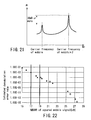
residual carrier component. Hence, as shown in
FIG. 21, the frequency characteristic measurement
circuit 104 sets the peak level which appears in
correspondence with the residual level of the carrier
frequency of the squared signal to be 30 dB or more
lower than the original peak level which appears at the
frequency twice the carrier frequency. In other words,
the circuit characteristics such as the frequency
characteristics, delay, and the like are adjusted so
that the residual peak level becomes 30 dB or more
lower than the original peak level which appears at the
frequency twice the predetermined frequency. More
specifically, the difference between the first and
second peaks of an output signal upon inputting an
ideal sine wave becomes 30 dB or more. In this way,
the NBSNR of squared wobble signal can be accurately
measured.
The third feature lies in the amplitude decreasing
rate after squaring. Normally, when a sine wave is
squared, its amplitude is nearly halved. Hence, the
CNR apparently lowers about 6 dB. However, if the
circuit has poor delay and frequency characteristics,
the decreasing amount of the amplitude after squaring
increases. If this decreasing amount is large, it
becomes difficult to accurately measure the NBSNR of
squared wobble signal. Therefore, upon reception of a
single-frequency wobble signal or an input signal
obtained by adding a noise component to an ideal sine
wave, the frequency characteristic measurement circuit
104 is adjusted so that the difference between the
NBSNR of original signal and NBSNR of squared signal
values is 7 dB or less. That is, upon inputting a
non-modulated sine wave with the NBSNR = 30 dB, the
NBSNR of squared sine signal becomes 23 dB or more. By
satisfying at least one of the aforementioned three
features, the NBSNR of squared signal can be accurately
measured.
FIG. 22 shows the relationship between the
measurement result of the NBSNR of squared wobble
signal, and the demodulation error rate of the
modulated wobble signal. The demodulation error rate
of the wobble signal is measured by, e.g., the address
information processing unit shown in FIGS. 1 and 10,
and the NBSNR of squared wobble signal is measured by,
e.g., the measurement unit shown in FIG. 18.
When physical address information or the like is
to be acquired from the wobble signal, it is generally
required that the demodulation error rate of a wobble
signal is 1.0 × 10⁻³ or less. If demodulation errors
more than this error rate have occurred, the address
information cannot be accurately read out. As a
result, it may become impossible to read out user
information, and information may be recorded at a wrong
recording destination (address). Conversely, if the
demodulation error rate is 1.0 × 10⁻³ or less, a
physical address can be nearly accurately specified by
error correction or confirming continuity of
neighboring addresses.
As can be seen from FIG. 22, in order to assure a
demodulation error rate of 1.0 × 10⁻³ or more, a
minimum of a NBSNR of squared wobble signal of 17 dB or
more is required. At this time, the NBSNR before
squaring requires about 23 dB to 24 dB. More
specifically, when the NBSNR of squared wobble signal
of the frequency characteristics obtained from the
wobbled track of the information storage medium shown
in FIG. 3 is 17 dB or more, physical addresses can be
accurately specified on this information storage
medium.
Upon measuring the NBSNR of squared wobble signal,
a measurement circuit may cause an error or read error
of around 1 dB. For this reason, a NBSNR of squared
wobble signal of 18 dB or more is preferably assured as
a measured value. That is, when the measurement result
of the squared wobble signal's NBSNR of the frequency
characteristics obtained from the wobbled track of the
information storage medium shown in FIG. 3 is 18 dB or
more, an actual NBSNR of squared wobble signal of 17 dB
or more can be reliably assured even when a read error
or the like occurs. Hence, physical addresses can be
accurately specified on this information storage
medium.
Upon reflecting address information or the like on
the wobble signal, it is often difficult to reflect
error correction codes together with the address
information or it is often required to determine the
read accuracy of a single physical address without
regarding the continuity of neighboring addresses so
as to improve the access speed. In such case, a
demodulation error rate of 1.0 × 10⁻⁵ or less must be
assured. The relationship in FIG. 22 reveals that a
NBSNR of squared wobble signal of 19 dB or more is
required to assure a demodulation error rate of 1.0 ×
10-5 or less. That is, when the NBSNR of squared
wobble signal of the frequency characteristics obtained
from the wobbled track of the information storage
medium shown in FIG. 3 is 19 dB or more, physical
addresses can be accurately assured and high-speed
access to a desired address is allowed on this
information storage medium, even when this information
storage medium has no error correction codes.
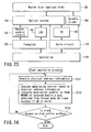
FIG. 23 is a block diagram showing an example of a
mastering apparatus as a part of a manufacturing system
for manufacturing the information storage medium shown
in FIG. 3. The optical disk of the present invention
is fabricated in master disk preparation, stamper
preparation, molding, medium film formation, and
adhesion processes. In the master disk preparation
process, a regist is applied to a flat master disk D0,
and is exposed by the mastering apparatus shown in
FIG. 23. Furthermore, the exposed regist is removed by
development, thus preparing a master disk having the
same three-dimensional pattern as that of the
information recording layer of the final optical disk
medium. In the stamper preparation process, Ni plating
or the like is applied to the master disk to form a
sufficiently thick metal disk, and the master disk is
peeled to prepare a stamper. At this time, the
three-dimensional pattern formed on the stamper is
inverted to that formed on the master disk. In the
molding process, a resin such as polycarbonate or the
like is poured using the stamper as a mold, thus
molding a substrate. The three-dimensional pattern on
the surface of the molded substrate is obtained by
copying that of the stamper, i.e., the substrate has
substantially the same three-dimensional pattern as
that of the master disk. Next, a film of a recording
material is formed on this three-dimensional pattern by
sputtering or the like, and another substrate is
adhered to that substrate to protect the formed film,
thus completing an optical disk D1. That is, the
wobbled track D13 is recorded by the mastering
apparatus shown in FIG. 23.
As shown in FIG. 23, the mastering apparatus
comprises a controller 110, formatter 120, wobble
control circuit 130, laser driver (LDD) 140, optical
system unit 150, photodetector (PD) 160, servo circuit
170, and spindle slider 180.
FIG. 24 is a flow chart showing an overview of the
mastering process by the mastering apparatus. The
controller 110 controls the overall mastering process.
The formatter 120 acquires physical address information
(ST11). Based on a signal output from this formatter
120 to the LDD 140, the amount of a laser beam emitted
by the optical system unit 150 is controlled. The
laser beam passes through an AO modulator, objective
lens, and the like included in the optical system unit
150, and strikes the master disk D0. Focusing,
tracking, and the like of the irradiated beam, rotation
of the disk, and the like are controlled by the servo
circuit 170. A portion irradiated with the laser beam
on the master disk D0 is exposed, and becomes a guide
groove (groove track) or the like.
The formatter 120 outputs a signal to the wobble
control circuit 130 on the basis of physical address
information and the like to be recorded on the optical
disk. The wobble control circuit 130 can slightly move
the spot of the beam that strikes the master disk in
the radial direction by controlling the AO modulator
and the like in the optical system unit. That is, the
wobble control circuit 130 controls the AO modulator
and the like in the optical system unit so that the
NBSNR of squared wobble signal NBSNR obtained from a
wobbled track formed on the disk becomes 17 dB or more
(ST12). Steps ST11 and ST12 are repeated until the
wobbled track is formed on the entire surface of the
disk (ST13). The optical disk prepared by the
aforementioned mastering process becomes an information
storage medium from which physical addresses can be
accurately read.
Next, quality evaluation of a reproduction signal
by the reproduction signal evaluation apparatus will
be explained below with reference to FIG. 25. As
described above, the reproduction signal evaluation
apparatus is formed by combining the measurement unit
shown in FIG. 18 and the optical disk apparatus shown
in FIG. 1. The PUH 40 irradiates the wobbled track D13
of the optical disk D1 with a light beam (ST21). The
PD 50 detects light reflected by the wobbled track D13
(ST22). A radial push-pull signal generated from the
signal detected by the PD 50, i.e., a wobble signal, is
input to the measurement unit shown in FIG. 18. The
squaring circuit 103 of the measurement unit squares
the wobble signal (ST23). The frequency characteristic
measurement circuit 104 checks based on the frequency
characteristics of a squared wobble signal if the
evaluation result of this squared wobble signal meets a
predetermined evaluation measure (ST24). That is,
it is determined whether or not the difference (NBSNR
of squared wobble signal) between the peak and noise
levels obtained from the frequency characteristics of
the squared wobble signal is 17 dB or more. If the
predetermined evaluation measure is met, i.e., if the
NBSNR of squared wobble signal is 17 dB or more (ST25,
YES), it is determined that the quality of the wobbled
track poses no problems (ST26). Hence, physical
addresses can be accurately read from the wobbled
track of this optical disk. Conversely, if the
predetermined evaluation measure is not met, i.e., if
the NBSNR of squared wobble signal is less than 17 dB
(ST25, NO), it is determined that the quality of the
wobbled track may pose problems (ST27). Hence,
physical addresses may not be accurately read from the
wobbled track of this optical disk.
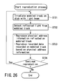
The reproduction process by the optical disk
apparatus shown in FIG. 1 will be described below with
reference to FIG. 26. An optical disk which is to
undergo the reproduction process is a disk which is
prepared via the aforementioned mastering process, and
is determined by the reproduction signal quality
evaluation process that the quality of its wobbled
track poses no problems. The PUH 40 irradiates the
wobbled track D13 of the optical disk D1 with a light
beam (ST31). The PD 50 detects light reflected by the
wobbled track D13 (ST32). A radial push-pull signal
generated from the signal detected by the PD 50, i.e.,
a wobble signal, is input to the address signal
processing unit 90. On the other hand, a sum signal
generated from the signal detected by the PD 50, i.e.,
an RF signal, is input to the RF signal processing
circuit 80. The address signal processing unit 90
reproduces physical address information on the basis of
the wobble signal (ST33). The RF signal processing
circuit 80 reproduces recorded data on the basis of the
RF signal. This optical disk is a disk which is
prepared via the aforementioned mastering process, and
is determined by the reproduction signal quality
evaluation process that the quality of its wobbled
track poses no problems. Hence, since a correct
address is read out from the wobbled track of this
optical disk, target information can be accurately
readout. Steps ST31 to ST33 are repeated until the
reproduction process of target data is completed
(ST34).
The recording process by the optical disk
apparatus shown in FIG. 1 will be described below with
reference to FIG. 27. An optical disk which is to
undergo the reproduction process is a disk which is
prepared via the aforementioned mastering process, and
is determined by the reproduction signal quality
evaluation process that the quality of its wobbled
track poses no problems. The PUH 40 irradiates the
wobbled track D13 of the optical disk D1 with a light
beam (ST41). The PD 50 detects light reflected by the
wobbled track D13 (ST42). A radial push-pull signal
generated from the signal detected by the PD 50, i.e.,
a wobble signal, is input to the address signal
processing unit 90. The address signal processing unit
90 reproduces physical address information on the basis
of the wobble signal (ST43). Based on the reproduced
physical address information, a target recording
position is recognized, and the PUH 40 records recording
data at the recognized target recording position
(ST44). This optical disk is a disk which is prepared
via the aforementioned mastering process, and is
determined by the reproduction signal quality evaluation
process that the quality of its wobbled track
poses no problems. Hence, since a correct address is
read out from the wobbled track of this optical disk,
target recording data can be accurately recorded at a
target position. Steps ST41 to ST44 are repeated until
the recording process of target data is completed
(ST45).