BACKGROUND OF THE INVENTION
Field of the Invention
-
The present invention relates to an anamorphic
converter suitable for a film camera, a television
camera, a video camera or the like which is disposed
on an image side of an imaging optical system in
order to convert an aspect ratio to photograph an
image having an aspect ratio different from that of
an image pickup element, a lens device using the same,
and an image pickup device such as a film camera, a
television camera, or a video camera using the same.
Related Background Art
-
As a technique for converting an aspect ratio
of an image to record and reproduce the resultant
image, up to this time, various techniques have been
proposed. In particular, for use in a motion picture,
a system in which an image is optically compressed
horizontally using an anamorphic lens to be
photographed on a film, and during the reproduction,
the image on the film is optically horizontally
magnified to be projected using an anamorphic lens as
well is generally used as a system for recording and
reproducing an image in compliance with the
CinemaScope form having an aspect ratio of 2.35 : 1.
As an anamorphic converter, a large number of front
converters each mounted on a side of an object of an
imaging optical system were proposed (refer to
Japanese Patent Application Laid-Open Nos. 48-24048,
2-13916, 3-25407, 5-188271, 5-188272, 6-82691 and
Japanese Patent No. 2,817,074 for example).
-
In addition, a rear converter mounted to an
image side of an imaging optical system was proposed
(refer to Japanese Patent No. 3,021,985 for example).
-
In recent years, promotion of high image
quality of the video technique has progressed, and a
digital cinema system for making a film of a scene
with an HDTV (High Definition Television) system is
in the progress of being popularized. In a digital
cinema system, an image pickup element having an
aspect ratio of 16 : 9 (1.78 : 1) is generally used.
However, for the photographing complying with the
CinemaScope form having the aspect ratio of 2.35 : 1,
there has been demanded an anamorphic converter for
effectively utilizing pixels on an image pickup
element to enhance image quality.
-
It is required for an anamorphic converter for
the cinema that the suitable aspect ratio conversion
is made, no eclipse is generated, an effective image
surface of an imaging optical system can be
sufficiently utilized, reduction in a quantity of
marginal ray is less, and high optical performance is
provided throughout zooming and focusing.
-
As described in Japanese Patent Application
Laid-Open Nos. 2-13916, 6-82691, and Japanese Patent
No. 2,817,074, the front converter type has
advantages that a structure is simple, and an
effective diameter is ensured irrespective of a
conversion ratio to avoid generation of the eclipse.
On the other hand, there is encountered a problem
that the size is large, and a change in astigmatism
due to focusing occurs.
-
In addition, as a technique for correction of
astigmatism due to focusing, there were proposed the
techniques described in Japanese Patent Application
Laid-Open Nos. 48-24048, 3-25407, 5-188271 and
5-188272. In these techniques, however, there is
encountered a problem that correction means within a
converter must be driven in conjunction with focusing
in an imaging optical system, and hence a complicated
mechanism is required.
-
The rear converter type has an advantage that
there occurs no change in astigmatism due to focusing.
However, a problem arises that when a conversion
magnification on a vertical side and a conversion
magnification are not suitably set, the eclipse is
generated and a field angle of an imaging optical
system is changed so that an effective image surface
can not be sufficiently utilized.
-
As the rear converter type, there are a system
having no primary image formation as shown in FIG. 31,
and a system having primary image formation as shown
in FIG. 32.
-
In FIGS. 31 and 32, α1 is an emission
inclination angle of axial marginal ray from an
imaging optical system, and α2 and α3 are emission
inclination angles of axial marginal ray from an
anamorphic converter AC.
-
In case of the rear converter type having no
primary image formation, as shown in FIG. 31, an
axial marginal ray from the imaging optical system
needs to be made nearly afocal with a negative lens.
At the same time, since an off-axial chief ray is
leapt up, an off-axial chief ray emission height hb2
from a converter final surface becomes large. Hence,
a problem occurs that vignetting is increased to
reduce a quantity of axial marginal ray, and an off-axial
chief ray emission inclination angle αb2 is
increased to shorten an exit pupil, and thus an
influence of the color shading by a color separation
optical system becomes easy to be generated.
-
The system having no primary image formation,
i.e., the rear converter in which both focal length
conversion magnifications βx and βy are positive
values is proposed in JP 3,021,985 B. In this case,
however, since the rear converter is prescribed so
that a positive refracting power is obtained in a
horizontal direction, and a negative refracting power
is obtained in a vertical direction, the rear
converter has an effect of lengthening a focal length
in addition to an effect of converting an aspect
ratio. As a result, there is a problem that a field
angle becomes narrow, and if the field angle is tried
to be ensured, then an image pickup means having a
larger image size is required, and if the image
pickup means having the larger image size is used,
then an exit pupil position becomes relatively short
so that an exit angle of an off-axial chief ray of a
peripheral portion of a screen becomes large, and
hence the shading or the like is generated.
SUMMARY OF THE INVENTION
-
In the light of the foregoing, it is an object
of the present invention to provide an anamorphic
converter of a rear converter system which is
especially most suitable for a converter for the
cinema, and which is miniature and excellent in
optical performance.
-
According to a first aspect of the present
invention, there is provided an anamorphic converter
uding at least an anamorphic lens and adapted to be disposed on an
image side of an imaging optical system,
in which when a focal length conversion
magnification in an arbitrary cross section X
containing an optical axis of the anamorphic
converter is assigned βx, a focal length conversion
magnification in a cross section Y containing an
optical axis and being perpendicular to the cross
section X is assigned βy, an aspect ratio of an image
pickup range in an image surface of the imaging
optical system is assigned AR1, and an aspect ratio
of an effective area of image pickup means is
assigned AR2, the following relationship is
established:
0.9 < (AR1 × βx) / (AR2 × βy) < 1.1
-
According to a second aspect of the present
invention, in the anamorphic converter according to
the first aspect of the invention, the anamorphic
lens is provided within an afocal group.
-
According to a third aspect of the present
invention, in the anamorphic converter according to
the first aspect of the invention, both βx and βy are
positive values, and the anamorphic converter has
positive refracting powers in the cross section X and
in the cross section Y.
-
According to a fourth aspect of the present
invention, the anamorphic converter according to the
third aspect of the invention further includes, from
the imaging optical system side in a stated order, a
first group of lenses having a negative refracting
power, a second group of lenses including at least
two or more anamorphic lenses, and a third group of
lenses having a positive refracting power.
-
According to a fifth aspect of the present
invention, in the anamorphic converter according to
the third aspect of the invention, the following
relationship is established:
1 ≤ (AR22 + 1) × βy/ (AR12 + 1) < 2.6
-
According to a sixth aspect of the present
invention, in the anamorphic converter according to
the first aspect of the invention, both βx and βy are
negative values, and the anamorphic converter further
includes at least one negative lens and two or more
anamorphic lenses.
-
According to a seventh aspect of the present
invention, there is provided an anamorphic converter
including at least an anamorphic lens disposed on an
image side of an imaging optical system,
in which when a focal length conversion
magnification in an arbitrary cross section X
containing an optical axis of the anamorphic
converter is assigned βx, and a focal length
conversion magnification in a cross section Y
containing an optical axis and being perpendicular to
the cross section X is assigned βy, both βx and βy
are negative values.
-
According to an eighth aspect of the present
invention, there is provided a lens device,
including:
- the anamorphic converter according to any one
of the first to seventh aspects of the invention; and
- the imaging optical system disposed on an
object side with respect to the anamorphic converter.
-
-
According to a ninth aspect of the present
invention, there is provided an image pickup device,
including:
- the anamorphic converter according to any one
of the first to seventh aspects of the invention;
- an imaging optical system disposed on an object
side with respect to the anamorphic converter; and
- image pickup means disposed on the object side
with respect to the anamorphic converter.
-
-
According to a tenth aspect of the present
invention, there is provided an anamorphic converter
including at least an anamorphic lens disposed on an
image side of an imaging optical system,
in which when a focal length conversion
magnification in an arbitrary cross section X
containing an optical axis of the anamorphic
converter is assigned βx, a focal length conversion
magnification in a cross section Y containing an
optical axis and being perpendicular to the cross
section X is assigned βy, an aspect ratio of an image
pickup range in an image surface of the imaging
optical system is assigned AR1, and an aspect ratio
of an effective area of image pickup means is
assigned AR2, the following relationships are
established:
0.9 < (AR1 × βx)/(AR2 × βy) < 1.1
(AR22 + 1) × βy2/ (AR12 + 1) < 1
-
According to an eleventh aspect of the present
invention, in the anamorphic converter according to
the tenth aspect of the invention, the anamorphic
lens is provided within an afocal group.
-
According to a twelfth aspect of the present
invention, in the anamorphic converter according to
the tenth aspect of the invention, both βx and βy are
positive values, and the anamorphic converter has
positive refracting powers in the cross section X and
in the cross section Y.
-
According to a thirteenth aspect of the present
invention, the anamorphic converter according to the
twelfth aspect of the invention further includes,
from the imaging optical system side in a stated
order, a first group of lenses having a negative
refracting power, a second group of lenses including
at least two or more anamorphic lenses, and a third
group of lenses having a positive refracting power.
-
According to a fourteenth aspect of the present
invention, in the anamorphic converter according to
the tenth aspect of the invention, both βx and βy are
negative values, and the anamorphic converter further
includes at least one negative lens and two or more
anamorphic lenses.
-
According to a fifteenth aspect of the present
invention, there is provided a lens device,
including:
- the anamorphic converter according to any one
of the tenth to fourteenth aspects of the invention;
and
- the imaging optical system disposed on an
object side with respect to the anamorphic converter.
-
-
According to a sixteenth aspect of the present
invention, there is provided an image pickup device,
including:
- the anamorphic converter according to any one
of the tenth to fourteenth aspects of the invention;
- the imaging optical system disposed on an
object side with respect to the anamorphic converter;
and
- image pickup means disposed on the object side
with respect to the anamorphic converter.
-
BRIEF DESCRIPTION OF THE DRAWINGS
-
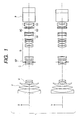
- FIG. 1 is a cross sectional view of a wide
angle end of Numerical Example 1 in an X direction
and in a Y direction;
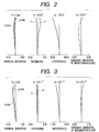
- FIG. 2 is a longitudinal aberration view of
Numerical Example 1 in the X direction under a
condition in which fx is 9.7 mm, fy is 12.9 mm, and
an object distance is 2.5 m;
- FIG. 3 is a longitudinal aberration view of
Numerical Example 1 in the Y direction under a
condition in which fx is 9.7 mm, fy is 12.9 mm, and
an object distance is 2.5 m;
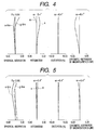
- FIG. 4 is a longitudinal aberration view of
Numerical Example 1 in the X direction under a
condition in which fx is 37.3 mm, fy is 49.3 mm and
the object distance is 2.5 m;
- FIG. 5 is a longitudinal aberration view of
Numerical Example 1 in the Y direction under a
condition in which fx is 37.3 mm, fy is 49.3 mm and
the object distance is 2.5 m;
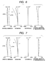
- FIG. 6 is a longitudinal aberration view of
Numerical Example 1 in the X direction under a
condition in which fx is 142.9 mm, fy is 189.0 mm and
the object distance is 2.5 m;
- FIG. 7 is a longitudinal aberration view of
Numerical Example 1 in the Y direction under a
condition in which fx is 142.9 mm, fy is 189.0 mm and
the object distance is 2.5 m;
- FIG. 8 is a cross sectional view of a wide
angle end of Numerical Example 2 in the X direction
and in the Y direction;
- FIG. 9 is a longitudinal aberration view of
Numerical Example 2 in the X direction under a
condition in which fx is 9.7 mm, fy is 12.9 mm and
the object distance is 2.5 m;
- FIG. 10 is a longitudinal aberration view of
Numerical Example 2 in the Y direction under a
condition in which fx is 9.7 mm, fy is 12.9 mm and
the object distance is 2.5 m;
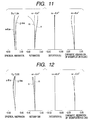
- FIG. 11 is a longitudinal aberration view of
Numerical Example 2 in the X direction under a
condition in which fx is 37.3 mm, fy is 49.3 mm and
the object distance is 2.5 m;
- FIG. 12 is a longitudinal aberration view of
Numerical Example 2 in the Y direction under a
condition in which fx is 37.3 mm, fy is 49.3 mm and
the object distance is 2.5 m;
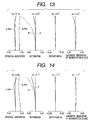
- FIG. 13 is a longitudinal aberration view of
Numerical Example 2 in the X direction under a
condition in which fx is 142.9 mm, fy is 189.0 mm and
the object distance is 2.5 m;
- FIG. 14 is a longitudinal aberration view of
Numerical Example 2 in the Y direction under a
condition in which fx is 142.9 mm, fy is 189.0 mm and
the object distance is 2.5 m;
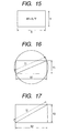
- FIG. 15 is a conceptual diagram of an aspect
ratio;
- FIG. 16 is a conceptual diagram of an image
circle and an image pickup range in an image surface
of an imaging optical system;
- FIG. 17 is a conceptual diagram of an image
circle and an image pickup range after conversion
made by a converter of the present invention;
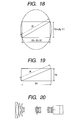
- FIG. 18 is a conceptual diagram of an effective
area of an image pickup means;
- FIG. 19 is a conceptual diagram of a display
area of an output image in projecting an image;
- FIG. 20 is a cross sectional view in a wide
angle end before insertion of an anamorphic converter
of Numerical Examples 1, 2, and 3;
- FIG. 21 is a longitudinal aberration view under
a condition in which f is 10.3 mm and the object
distance is 2.5 m before insertion of the anamorphic
converter of Numerical Examples 1, 2, and 3;
- FIG. 22 is a longitudinal aberration view under
a condition in which f is 39.5 mm and the object
distance is 2.5 m before insertion of the anamorphic
converter of Numerical Examples 1, 2, and 3;
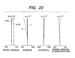
- FIG. 23 is a longitudinal aberration view under
a condition in which f is 151.1 mm and the object
distance is 2.5 m before insertion of the anamorphic
converter of Numerical Examples 1, 2, and 3;
- FIG. 24 is a cross sectional view in a wide
angle end of Numerical Example 3 in the X direction
and in the Y direction;
- FIG. 25 is a longitudinal aberration view of
Numerical Example 3 in the X direction under a
condition in which fx is -9.7 mm, fy is -12.9 mm and
the object distance is 2.5 m;
- FIG. 26 is a longitudinal aberration view of
Numerical Example 3 in the Y direction under a
condition in which fx is -9.7 mm, fy is -12.9 mm and
the object distance is 2.5 m;
- FIG. 27 is a longitudinal aberration view of
Numerical Example 3 in the X direction under a
condition in which fx is -37.3 mm, fy is -49.3 mm and
the object distance is 2.5 m;
- FIG. 28 is a longitudinal aberration view of
Numerical Example 3 in the Y direction under a
condition in which fx is -37.3 mm, fy is -49.3 mm and
the object distance is 2.5 m;
- FIG. 29 is a longitudinal aberration view of
Numerical Example 3 in the X direction under a
condition in which fx is -142.9 mm, fy is -189.0 mm
and the object distance is 2.5 m;
- FIG. 30 is a longitudinal aberration view of
Numerical Example 3 in the Y direction under a
condition in which fx is -142.9 mm, fy is -189.0 mm
and the object distance is 2.5 m;
- FIG. 31 is a conceptual view of an anamorphic
converter of a type having no primary image
formation;
- FIG. 32 is a conceptual view of an anamorphic
converter of a type having primary image formation;
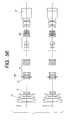
- FIG. 33 is a cross sectional view in a wide
angle end of Numerical Example 4 in the X direction
and in the Y direction;
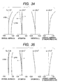
- FIG. 34 is a longitudinal aberration view of
Numerical Example 4 in the X direction under a
condition in which fx is 7.90 mm, fy is 10.44 mm and
the object distance is 2.5 m;
- FIG. 35 is a longitudinal aberration view of
Numerical Example 4 in the Y direction under a
condition in which fx is 7.90 mm, fy is 10.44 mm and
the object distance is 2.5 m;
- FIG. 36 is a longitudinal aberration view of
Numerical Example 4 in the X direction under a
condition in which fx is 30.24 mm, fy is 39.98 mm and
the object distance is 2.5 m;
- FIG. 37 is a longitudinal aberration view of
Numerical Example 4 in the Y direction under a
condition in which fx is 30.24 mm, fy is 39.98 mm and
the object distance is 2.5 m;
- FIG. 38 is a longitudinal aberration view of
Numerical Example 4 in the X direction under a
condition in which fx is 115.83 mm, fy is 153.12 mm
and the object distance is 2.5 m;
- FIG. 39 is a longitudinal aberration view of
Numerical Example 4 in the Y direction under a
condition in which fx is 115.83 mm, fy is 153.12 mm
and the object distance is 2.5 m;
- FIG. 40 is a cross sectional view in a wide
angle and of Numerical Example 5 in the X direction
and in the Y direction;
- FIG. 41 is a longitudinal aberration view of
Numerical Example 5 in the X direction under a
condition in which fx is 7.34 mm, fy is 9.71 mm and
the object distance is 2.5 m;
- FIG. 42 is a longitudinal aberration view of
Numerical Example 5 in the Y direction under a
condition in which fx is 7.34 mm, fy is 9.71 mm and
the object distance is 2.5 m;
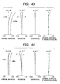
- FIG. 43 is a longitudinal aberration view of
Numerical Example 5 in the X direction under a
condition in which fx is 28.12 mm, fy is 37.18 mm and
the object distance is 2.5 m;
- FIG. 44 is a longitudinal aberration view of
Numerical Example 5 in the Y direction under a
condition in which fx is 28.12 mm, fy is 37.18 mm and
the object distance is 2.5 m;
- FIG. 45 is a longitudinal aberration view of
Numerical Example 5 in the X direction under a
condition in which fx is 107.72 mm, fy is 142.41 mm
and the object distance is 2.5 m;
- FIG. 46 is a longitudinal aberration view of
Numerical Example 5 in the Y direction under a
condition in which fx is 107.72 mm, fy is 142.41 mm
and the object distance is 2.5 m;
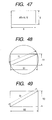
- FIG. 47 is a conceptual diagram of an aspect
ratio;
- FIG. 48 is a conceptual diagram of an image
circle and an image pickup range in an image surface
of a main lens;
- FIG. 49 is a conceptual diagram of an image
circle and an image pickup range after conversion
made by a converter of the present invention;
- FIG. 50 is a conceptual diagram of an effective
area of an image pickup means;
- FIG. 51 is a conceptual diagram of a display
area of an output image in projecting an image;
- FIG. 52 is a cross sectional view in a wide
angle end before insertion of an anamorphic converter
of Numerical Examples 4, 5, and 6;
- FIG. 53 is a longitudinal aberration view under
a condition in which f is 10.3 mm and the object
distance is 2.5 m before insertion of the anamorphic
converter of Numerical Examples 4, 5, and 6;
- FIG. 54 is a longitudinal aberration view under
a condition in which f is 39.5 mm and the object
distance is 2.5 m before insertion of the anamorphic
converter of Numerical Examples 4, 5, and 6;
- FIG. 55 is a longitudinal aberration view under
a condition in which f is 151.1 mm and the object
distance is 2.5 m before insertion of the anamorphic
converter of Numerical Examples 4, 5, and 6;
- FIG. 56 is a cross sectional view in a wide
angle end of Numerical Example 6 in the X direction
and in the Y direction;
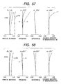
- FIG. 57 is a longitudinal aberration view of
Numerical Example 6 in the X direction under a
condition in which fx is -7.11 mm, fy is -9.40 mm and
the object distance is 2.5 m;
- FIG. 58 is a longitudinal aberration view of
Numerical Example 6 in the Y direction under a
condition in which fx is -7.11 mm, fy is -9.40 mm and
the object distance is 2.5 m;
- FIG. 59 is a longitudinal aberration view of
Numerical Example 6 in the X direction under a
condition in which fx is -27.25 mm, fy is -36.01 mm
and the object distance is 2.5 m;
- FIG. 60 is a longitudinal aberration view of
Numerical Example 6 in the Y direction under a
condition in which fx is -27.25 mm, fy is -36.01 mm
and the object distance is 2.5 m;
- FIG. 61 is a longitudinal aberration view of
Numerical Example 6 in the X direction under a
condition in which fx is -104.37 mm, fy is -137.96 mm
and the object distance is 2.5 m;
- FIG. 62 is a longitudinal aberration view of
Numerical Example 6 in the Y direction under a
condition in which fx is -104.37 mm, fy is -137.96 mm
and the object distance is 2.5 m;
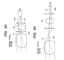
- FIG. 63 is a conceptual view of an anamorphic
converter of a type having no primary image
formation; and
- FIG. 64 is a conceptual view of an anamorphic
converter of a type having primary image formation.
-
DETAILED DESCRIPTION OF THE PREFERRED EMBODIMENTS
(Operation 1)
Aspect 1
-
An anamorphic converter according to the
present invention includes at least an anamorphic
lens disposed on an image side of an imaging optical
system, and the anamorphic converter is characterized
in that when a focal length conversion magnification
in an arbitrary cross section X containing an optical
axis of the anamorphic converter is assigned βx, a
focal length conversion magnification in a cross
section Y containing an optical axis and being
perpendicular to the cross section X is assigned βy,
an aspect ratio of an image pickup range in an image
surface of the imaging optical system is assigned AR1,
and an aspect ratio of an effective area of image
pickup means is assigned AR2, the following
relationship is established:
0.9 < (AR1 × βx)/(AR2 × βy) < 1.1
-
Aspect 1 is concerned with a condition under
which the conversion magnification of the anamorphic
converter is suitably prescribed to thereby carry out
the suitable conversion of an aspect ratio without
generation of an eclipse.
-
Equation 1 exhibits with a condition under
which the suitable aspect ratio conversion is carried
out. When as shown in FIG. 15, a transverse length
of an image surface is assigned X, a longitudinal
length of the image surface is assigned Y, an aspect
ratio AR is expressed by Equation 2:
AR = X/Y
A schematic diagram of an image pickup range of an
imaging optical system is shown in FIG. 16, and a
schematic diagram of an image pickup range of an
image pickup means is shown in FIG. 17. When from
FIG. 16, a transverse length of a size of an
effective picture of the image pickup range in the
image surface of the imaging optical system is
assigned X1, a longitudinal length of the size of
that effective picture is assigned Y1, and an aspect
ratio is assigned AR1, and from FIG. 17, a transverse
length of the image pickup range of the image pickup
means is assigned X2, a longitudinal length of that
image pickup range is assigned Y2, and an aspect
ratio is assigned AR2, a ratio of AR1/AR2 is
expressed by Equation 3:
AR1/AR2 = (X1 × Y2)/(X2 × Y1)
In addition, a conceptual diagram of an image pickup
range after the conversion of the aspect ratio made
by the anamorphic converter is shown in FIG. 18. In
order that the aspect ratio may be suitably converted,
it is desirable that a conversion magnifications βx
of the anamorphic converter in a transverse direction,
and a conversion magnification βy of the anamorphic
converter in a longitudinal direction are expressed
by Equations 4 and 5, respectively:
βx = X2/X1
βy = Y2/Y1
From Equations 3 to 5, the condition for ideal aspect
ratio conversion is expressed as follows:
(AR1 × βx) / (AR2 × βy) = 1
Since in actual, an influence of an error of about
10% is visually small, Equation 1 is met to thereby
allow the suitable aspect ratio conversion to be
realized.
-
Also, a conceptual diagram of an output image
in projecting an image is shown in FIG. 19. It is
necessary that in projecting an image, the conversion
of the aspect ratio reverse to that in capturing an
image is carried out to return the current aspect
ratio back to the original aspect ratio.
Consequently, a transverse length X4 and a
longitudinal length Y4 in FIG. 19 are expressed as
follows, respectively:
X4 = βx' × X2
Y4 = βy' × Y2
Here, the conversion magnifications βx' and βy', when
an arbitrary constant is assigned m, are expressed as
follows, respectively:
βx' = m/βx
βy' = m/βy
Aspect 2
-
There is provided an anamorphic converter
according to Aspect 1, in which the anamorphic lens
is provided within an afocal group.
Aspect 3
-
There is provided an anamorphic converter
according to Aspect 1 or 2, characterized in that
both βx and βy are positive values, and the
anamorphic converter has positive refracting powers
in the cross section X and in the cross section Y.
Aspect 4
-
There is provided an anamorphic converter
according to Aspect 3, further including, from the
imaging optical system side in a stated order, a
first group of lenses having a negative refracting
power, a second group of lenses including at least
two or more anamorphic lenses, and a third group of
lenses having a positive refracting power.
Aspect 5
-
There is provided an anamorphic converter
according to Aspect 3 or 4, characterized in that the
following relationship is established:
1 ≤ (AR22 + 1) × βy2/ (AR12 + 1) < 2.6
-
Aspect 4 is concerned with a condition under
which the power disposition of the anamorphic
converter for carrying out the aspect ratio
conversion without the primary image formation by an
imaging optical system is suitably prescribed to make
the optical performance excellent.
-
In order that the primary imaging may be
prevented from being made, it is necessary that both
the focal length conversion magnifications βx and βy
are positive values. Moreover, the cross section X
and the cross section Y have positive refracting
powers, respectively, to thereby reduce the effect of
lengthening a focal length. As a result, there is
obtained the anamorphic converter of a type having no
primary image formation in which for the single
imaging optical system, the field angle is prevented
from becoming too narrow, and the exit pupil can be
held for long.
-
In Aspect 4, the suitable structure in Aspect 3
is prescribed. In order that the cross section X and
the cross section Y may have different conversion
magnifications, it is necessary to form an afocal
converter (anamorphic converter) having different
angular magnifications in the cross section X and the
cross section Y by using at least two so-called toric
lenses each having different curvatures in the cross
section X and the cross section Y, or at least two
cylindrical lenses having a curvature in a certain
cross section. In addition, in order that the
converter may be disposed on an image side of the
imaging optical system, there are required a first
group of lenses having a negative refracting power
for causing a converged ray from the imaging optical
system to diverge, and a group of lenses having a
positive refracting power for imaging that ray.
Consequently, an optical property of a portion
between the first group of lenses having a negative
refracting power and the group of lenses having a
positive refracting power is made nearly afocal, and
a group of lenses including an anamorphic lens is
introduced as the second group of lenses, whereby it
is possible to attain an anamorphic converter having
no primary image formation.
-
In Aspect 5, there is prescribed a relationship
among the focal length conversion magnification βy,
and the aspect ratios AR1 and AR2 for preventing the
field angle from becoming too narrow while preventing
generation of the eclipse in Aspect 3 or Aspect 4.
-
Equation (11) exhibits a condition under which
reduction in the field angle is suppressed while
preventing generation of the eclipse following the
aspect ratio conversion. When the converter is
disposed on an image side of the imaging optical
system, since an image circle is regulated on the
basis of the effective diameter on the side of the
imaging optical system, the wide angle can not be
obtained even if the conversion magnification is made
smaller than 1. Consequently, the eclipse is
generated in the periphery of the picture.
-
As shown in FIG. 16, an image circle I1 of the
imaging optical system is expressed by Equation 12:
I1 = (X12 + Y12) ½ = Y1 × (AR12 + 1)½
In addition, as shown in FIG. 17, a width I2 across
corners of the image pickup means is expressed by
Equation 13:
I2 = (X22 + Y22) ½
= βy × Y1 × (AR22 + 1) ½
Here, as shown in FIG. 18, a width I3 across corners
of the image which is subjected to the aspect ratio
conversion in the anamorphic converter is expressed
by Equation 14:
I3 = {(βx × X1)2 + (βy × Y1)2}½
= βy × Y1 × (AR22 + 1) ½
Consequently, in order that the image after the
aspect ratio conversion may contain the width across
corners of the image pickup means to prevent
generation of the eclipse, a relationship of I3 ≥ I2
must be established. Thus, from Equations 13 and 14,
Equations 15 and 11-2 are obtained:
I32/I22 ≥ 1
{βy2 × (AR22 + 1)}/(AR12 + 1) ≥ 1
As a result, if the lower limit in Equation (11) is
exceeded, the eclipse will be generated.
-
In addition, if the upper limit in Equation 11
is exceeded, then the field angle obtained through
the conversion made by the converter becomes narrower
than that in the single imaging optical system, so
that the image pickup range of the imaging optical
system becomes unable to be effectively utilized.
Aspect 6
-
There is provided an anamorphic converter
according to Aspect 1 or 2, in which both βx and βy
are negative values, and the anamorphic converter
includes at least one negative lens and two or more
anamorphic lenses.
Aspect 7
-
There is provided an anamorphic converter
including at least an anamorphic lens disposed on an
image side of an imaging optical system, in which
when a focal length conversion magnification in an
arbitrary cross section X containing an optical axis
of the anamorphic converter is assigned βx, and a
focal length conversion magnification in a cross
section Y containing an optical axis and being
perpendicular to the cross section X is assigned βy,
both βx and βy are negative values.
-
Aspects 6 and 7 are concerned with a condition
in which a structure of the anamorphic converter for
obtaining the primary image formation through the
imaging optical system to convert the aspect ratio is
suitably prescribed to make the optical performance
excellent.
-
A conceptual view of the anamorphic converter
of a type having primary image formation is shown in
FIG. 32. For the optical system for reimaging the
primary image of the imaging optical system, it is
necessary that both the focal length conversion
magnifications βx and βy are negative values. In
addition, in order to contain the marginal ray of the
imaging optical system, it is necessary that an
entrance pupil nearly agrees with the exit pupil of
the imaging optical system. Lenses for broadcasting
including a lens for a digital cinema become an
optical system which has a long exit pupil and hence
is nearly telecentric on the image side since they
are established on the assumption that the color
separation optical system is used. Consequently, an
optical system which is at least nearly telecentric
on the both sides is required for the converter. As
shown in FIG. 32, in case of the anamorphic converter
of a type having primary image formation, since an
emitted ray from the imaging optical system is made
nearly afocal using the positive lens, an increase in
an off-axial chief ray emitted height hb3 from the
converter final surface is suppressed to prevent a
quantity of marginal light from being reduced. Thus,
an off-axial chief ray emitted inclination angle αb3
can be made small. As a result, there is an
advantage that the exit pupil becomes long, and hence
an influence of the color shading due to the color
separation optical system is hardly generated. As
shown in FIG. 32, from the condition in which the
converter is telecentric on the both sides, the
anamorphic converter of a type having primary image
formation is constituted by at least two groups of
positive lenses, and the refracting power of the
whole converter takes a minute value in the vicinity
of zero.
-
In addition, since for the primary image
obtained through the imaging optical system, the
various aberrations such as the chromatic aberration,
the antigmatism and the curvature of field are
satisfactorily corrected, the chromatic aberration,
the antigmatism, the curvature of field and the like
of the converter must also be satisfactorily
corrected. When a refracting power of an i-th lens
of lenses within the converter is assigned Φi, an
Abbe's number of the i-th lens of the lenses is
assigned vi, and a refracting index of the i-th lens
of the lenses is assigned Ni, a chromatic aberration
correction condition is expressed as follows:
Σ (Φi/νi) ≈ 0
Also, a Petzval's condition is expressed as follows:
Σ (Φi/Ni) ≈ 0
Here, since in the general optical materials, νi > 0
and Ni > 0 are established, in order to meet
Equations (16) and (17), the anamorphic converter
having primary image formation must have at least an
negative lens in terms of its structure. Moreover,
any one of the intervals within the converter is made
nearly afocal, and the lens group including the
above-mentioned anamorphic lens is introduced,
whereby it is possible to attain the anamorphic
converter of a primary image formation type.
Aspect 8
-
There is provided a lens device, including: the
anamorphic converter according to any one of Aspects
1 to 7; and the imaging optical system disposed on an
object side with respect to the anamorphic converter.
Aspect 9
-
There is provided an image pickup device,
including: the anamorphic converter according to any
one of Aspects 1 to 8; an imaging optical system
disposed on an object side with respect to the
anamorphic converter; and image pickup means disposed
on the object side with respect to the anamorphic
converter.
-
The anamorphic lens used in the present
invention is used in terms of the concept including a
toric lens and a cylindrical lens, and hence means a
lens in which a power in the X direction is different
from that in the Y direction.
-
In addition, the anamorphic lens used in the
present invention may have a function of a
diffraction system.
-
Moreover, the imaging optical system of the
present invention may be a variable power system or a
fixed power system (having no variable power).
(First Embodiment)
-
This embodiment is concerned with an anamorphic
converter of a type having no primary image formation.
-
FIG. 1 is a cross sectional view of lenses in a
Y direction and in an X direction when an anamorphic
converter is inserted in Numerical Example 1 of the
present invention.
-
In addition, a cross sectional view before
insertion of the anamorphic converter in Numerical
Example 1 is shown in FIG. 20.
-
FIGS. 21 to 23 show longitudinal aberration
views before insertion of the anamorphic converter in
Numerical Examples 1, 2, and 3, respectively.
-
In FIG. 1, reference symbol F designates a
group of front focusing lenses having a positive
refracting power as a first group. Reference symbol
V designates a variator for the variable power having
a negative refracting power as a second group. The
variator V is monotonously moved on an optical axis
to an image surface side to thereby carry out the
variable power from the wide angle end to the
telescopic end. Reference symbol C designates a
compensator having a negative refracting power as a
third group. The compensator C is nonlinearly moved
on the optical axis to an object side while
describing a projection locus in order to compensate
for the fluctuation of an image surface following the
variable power. The variator V and the compensator C
constitute the variable power system.
-
Reference symbol SP designates a stop, and
reference symbol R designates a group of variable
power semi-fixed relay lenses having a positive
refracting power as a fourth group. Reference symbol
P designates a color separation prism, an optical
filter or the like which is shown in the form of a
glass block in the figure.
-
The focusing group F, the variator V, the
compensator C and the relay group R constitute an
imaging optical system.
-
Next, a description will hereinafter be given
with respect to the feature of the anamorphic
converter AC in Numerical Example 1. The anamorphic
converter AC includes: a first group G1 of lenses
having a negative refracting power; a second group G2
of lenses having two cylindrical lenses; and a third
group G3 of lenses having an image formation function
and a positive refracting power. Each of the
cylindrical lenses belonging to the second group G2
has a curvature only in the X direction, and has an
effect of shortening a focal length in the X
direction. The aspect ratio AR1 of the image pickup
range in the image surface of the imaging optical
system, and the aspect ratio AR2 of the effective
area of the image pickup means are as follows:
AR1 = 2.35
AR2 = 1.78
Also, the conversion magnification βx in the X
direction, and the conversion magnification βy in the
Y direction are as follows:
βx = 0.947
βy = 1.252
Consequently, the values of the conditional equations
are obtained as follows:
(AR1 × βx)/(AR2 × βy) = 1.00
(AR22 + 1) × β2/ (AR12 + 1) = 1.00
Thus, these values meet the conditions of Equations 1
and 11. Consequently, the anamorphic converter of a
built-in converter system is attained which is
excellent in the optical performance and free from
the eclipse.
-
In addition, in case of the single anamorphic
converter AC, a focal length fACx in the X direction,
and a focal length fACy in the Y direction are
expressed as follows:
fACx = +32.789
fACy = +69.848
Thus, both of them have the positive refracting
powers and hence meet the condition which is required
for the anamorphic converter of the present invention.
-
A material of the cylindrical lens used in this
embodiment is glass. In the following second and
third embodiments as well, the same material will be
used.
-
FIGS. 2 to 7 are longitudinal aberration views
in the X direction or in the Y direction in Numerical
Example 1. In these figures, fx indicates a focal
length in the X direction, fy indicates a focal
length in the Y direction, Fx indicates an F number
in the X direction, Fy indicates an F number in the Y
direction, and 2ω indicates a field angle.
-
In Numerical Example 1, the following values
are obtained:
- fx = 9.74 to 142.93
- fy = 12.88 to 188.96
- Fx = 1.94 to 2.19
- Fy = 2.56 to 2.90
- 2ω = 56.2 to 4.2 degrees
| r 1= 1169.481 | d 1= 2.40 | n 1= 1.81265 | v 1= 25.4 |
| r 2= 98.429 | d 2= 10.83 | n 2= 1.51825 | v 2= 64.2 |
| r 3= 265.170 | d 3= 0.20 |
| r 4= 124.037 | d 4= 8.29 | n 3= 1.60548 | v 3= 60.7 |
| r 5= -281.395 | d 5= 0.20 |
| r 6= 51.797 | d 6= 6.46 | n 4= 1.64254 | v 4= 60.1 |
| r 7= 97.915 | d 7= Variable |
| r 8= 71.045 | d 8= 0.90 | n 5= 1.82017 | v 5= 46.6 |
| r 9= 17.601 | d 9= 6.01 |
| r10= -21.542 | d10= 0.90 | n 6= 1.77621 | v 6= 49.6 |
| r11= 18.397 | d11= 4.63 | n 7= 1.85501 | v 7= 23.9 |
| r12= -4295.134 | d12= Variable |
| r13= -27.245 | d13= 0.90 | n 8= 1.79013 | v 8= 44.2 |
| r14= 31.613 | d14= 3.84 | n 9= 1.85501 | v 9= 23.9 |
| r15= 1125.345 | d15= Variable |
| r16= 0.000 (Stop) | d16= 1.60 |
| r17= 10000.000 | d17= 4.02 | n10= 1.73234 | v10= 54.7 |
| r18= -32.342 | d18= 0.20 |
| r19= 107.938 | d19= 3.60 | n11= 1.48915 | v11= 70.2 |
| r20= -121.402 | d20= 0.20 |
| r21= 37.891 | d21= 7.17 | n12= 1.48915 | v12= 70.2 |
| r22= -36.452 | d22= 1.20 | n13= 1.83932 | v13= 37.2 |
| r23= 177.431 | d23= 30.00 |
| r24= 48.564 | d24= 4.26 | n14= 1.48915 | v14= 70.2 |
| r25= -193.706 | d25= 0.20 |
| r26= -210.911 | d26= 1.20 | n15= 1.83932 | v15= 37.2 |
| r27= 39.960 | d27= 6.49 | n16= 1.48915 | v16= 70.2 |
| r28= -33.683 | d28= 0.20 |
| r29= 43.464 | d29= 6.21 | n17= 1.53430 | v17= 48.8 |
| r30= -30.063 | d30= 1.20 | n18= 1.80811 | v18= 46.6 |
| r31= 113.246 | d31= 0.20 |
| r32= 56.783 | d32= 2.98 | n19= 1.55098 | v19= 45.8 |
| r33= -10000.000 | d33= 2.40 |
| r34= -7839.440 | d34= 1.50 | n20= 1.88815 | v20= 40.8 |
| r35= 23.812 | d35= 11.72 |
| r36= -53.891 | d36= 1.50 | n21= 1.88815 | v21= 40.8 |
| r37= -398.617 | d37= 0.20 |
| r38= 70.482 | d38= 6.77 | n22= 1.81264 | v22= 25.4 |
| r39= -44.050 | d39= 0.31 |
| r40= -53.902 | d40= 1.50 | n23= 1.51825 | v23= 64.1 |
| r41= 63.160 | d41= 13.52 |
| r42= 128.438 | d42= 4.68 | n24= 1.88815 | v24= 40.8 |
| r43= 80.144 | d43= 0.20 |
| r44= 42.096 | d44= 8.88 | n25= 1.48915 | v25= 70.2 |
| r45= -35.579 | d45= 1.50 | n26= 1.81264 | v26= 25.4 |
| r46= 357.584 | d46= 0.20 |
| r47= 199.741 | d47= 5.28 | n27= 1.48915 | v27= 70.2 |
| r48= 46.226 | d48= 2.00 |
| r49= 0.000 | d49= 30.00 | n28= 1.60718 | v28= 38.0 |
| r50= 0.000 | d50= 16.20 | n29= 1.51825 | v29= 64.2 |
| r51= 0.000 |
| * r40 to r43 indicate the cylindrical lenses. A curvature in the Y direction is zero. |
| Focal length fx | 9.74 | 37.31 | 142.93 |
| fy | 12.88 | 49.33 | 188.96 |
| Variable spacing |
| d7 | 0.39 | 33.92 | 49.55 |
| d12 | 52.91 | 14.8 | 3.78 |
| d15 | 1.55 | 6.13 | 1.53 |
-
(Second Embodiment)
-
This embodiment is concerned with an anamorphic
converter of a type having no primary image formation.
-
FIG. 8 is a cross sectional view of lenses in a
Y direction and in an X direction when an anamorphic
converter is inserted in Numerical Example 2 of the
present invention. In addition, a cross sectional
view before insertion of the anamorphic converter in
Numerical Example 2 is shown in FIG. 20.
-
In FIG. 8, reference symbol F designates a
group of front lenses having a positive refracting
power as a first group. Reference symbol V
designates a variator for the variable power having a
negative refracting power as a second group. The
variator V is monotonously moved on an optical axis
to an image surface side to thereby carry out the
variable power from the wide angle end to the
telescopic end. Reference symbol C designates a
compensator having a negative refracting power as a
third group. The compensator C is nonlinearly moved
on the optical axis to an object side while
describing a projection locus in order to compensate
for the fluctuation of an image surface following the
variable power. The variator V and the compensator C
constitute the variable power system.
-
Reference symbol SP designates a stop, and
reference symbol R designates a group of variable
power semi-fixed relay lenses having a positive
refracting power as a fourth group. Reference symbol
P designates a color separation prism, an optical
filter or the like which is shown in the form of a
glass block in the figure.
-
The focusing group F, the variator V, the
compensator C and the relay group R constitute an
imaging optical system.
-
Next, a description will hereinafter be given
with respect to the feature of the anamorphic
converter AC in Numerical Example 2. The anamorphic
converter AC includes: a first group G1 of lenses
having a negative refracting power; a second group G2
of lenses having two cylindrical lenses; and a third
group G3 of lenses having an image formation function
and a positive refracting power. Each of the
cylindrical lenses belonging to the second group G2
has a curvature only in the Y direction, and has an
effect of lengthening a focal length in the Y
direction. The aspect ratio AR1 of the image pickup
range in the image surface of the imaging optical
system, and the aspect ratio AR2 of the effective
area of the image pickup means are as follows:
AR1 = 2.35
AR2 = 1.78
Also, the conversion magnification βx in the X
direction, and the conversion magnification βy in the
Y direction are as follows:
βx = 0.947
βy = 1.252
Consequently, the values of the conditional equations
are obtained as follows:
(AR1 × βx) / (AR2 × βy) = 1.00
(AR22 + 1) × βy2/ (AR12 + 1) = 1.00
Thus, these values meet the conditions of Equations 1
and 11. Consequently, the anamorphic converter of a
built-in converter system is attained which is
excellent in the optical performance and free from
the eclipse.
-
In addition, in case of the single anamorphic
converter AC, a focal length fACx in the X direction,
and a focal length fACy in the Y direction are
expressed as follows:
fACx = +36.688
fACy = +81.334
Thus, both of them have the positive refracting
powers and hence meet the condition which is required
for the anamorphic converter of the present invention.
-
FIGS. 8 to 14 are longitudinal aberration views
in the X direction or in the Y direction in Numerical
Example 2. In these figures, fx indicates a focal
length in the X direction, fy indicates a focal
length in the Y direction, Fx indicates an F number
in the X direction, Fy indicates an F number in the Y
direction, and 2ω indicates a field angle.
-
In Numerical Example 2, the following values
are obtained:
- fx = 9.74 to 142.93
- fy = 12.88 to 188.96
- Fx = 1.94 to 2.19
- Fy = 2.56 to 2.90
- 2ω = 56.2 to 4.2 degrees
| r 1= 1169.481 | d 1= 2.40 | n 1= 1.81265 | v 1= 25.4 |
| r 2= 98.429 | d 2= 10.83 | n 2= 1.51825 | v 2= 64.2 |
| r 3= -265.170 | d 3= 0.20 |
| r 4= 124.037 | d 4= 8.29 | n 3= 1.60548 | v 3= 60.7 |
| r 5= -281.395 | d 5= 0.20 |
| r 6= 51.797 | d 6= 6.46 | n 4= 1.64254 | v 4= 60.1 |
| r 7= 97.915 | d 7= Variable |
| r 8= 71.045 | d 8= 0.90 | n 5= 1.82017 | v 5= 46.6 |
| r 9= 17.601 | d 9= 6.01 |
| r10= -21.542 | d10= 0.90 | n 6= 1.77621 | v 6= 49.6 |
| r11= 18.397 | d11= 4.63 | n 7= 1.85501 | v 7= 23.9 |
| r12= -4295.134 | d12= Variable |
| r13= -27.245 | d13= 0.90 | n 8= 1.79013 | v 8= 44.2 |
| r14= 31.613 | d14= 3.84 | n 9= 1.85501 | v 9= 23.9 |
| r15= 1125.345 | d15= Variable |
| r16= 0.000 (Stop) | d16= 1.60 |
| r17= 10000.000 | d17= 4.02 | n10= 1.73234 | v10= 54.7 |
| r18= -32.342 | d18= 0.20 |
| r19= 107.938 | d19= 3.60 | n11= 1.48915 | v11= 70.2 |
| r20= -121.402 | d20= 0.20 |
| r21= 37.891 | d21= 7.17 | n12= 1.48915 | v12= 70.2 |
| r22= -36.452 | d22= 1.20 | n13= 1.83932 | v13= 37.2 |
| r23= 177.431 | d23= 30.00 |
| r24= 48.564 | d24= 4.26 | n14= 1.48915 | v14= 70.2 |
| r25= -193.706 | d25= 0.20 |
| r26= -210.911 | d26= 1.20 | n15= 1.83932 | v15= 37.2 |
| r27= 39.960 | d27= 6.49 | n16= 1.48915 | v16= 70.2 |
| r28= -33.683 | d28= 0.20 |
| r29= 43.464 | d29= 6.21 | n17= 1.53430 | v17= 48.8 |
| r30= -30.063 | d30= 1.20 | n18= 1.80811 | v18= 46.6 |
| r31= 113.246 | d31= 0.20 |
| r32= 56.783 | d32= 2.98 | n19= 1.55098 | v19= 45.8 |
| r33= -10000.000 | d33= 2.40 |
| r34= -406.116 | d34= 1.30 | n20= 1.88815 | v20= 40.8 |
| r35= 27.624 | d35= 5.09 |
| r36= -34.561 | d36= 1.30 | n21= 1.88815 | v21= 40.8 |
| r37= 376.875 | d37= 2.39 |
| r38= 125.238 | d38= 6.87 | n22= 1.81264 | v22= 25.4 |
| r39= -35.789 | d39= 0.20 |
| r40= 51.579 | d40= 5.00 | n23= 1.73234 | v23= 54.7 |
| r41= -179.240 | d41= 10.68 |
| r42= -89.456 | d42= 1.50 | n24= 1.83932 | v24= 37.2 |
| r43= 57.960 | d43= 2.62 |
| r44= 56.863 | d44= 8.20 | n25= 1.48915 | v25= 70.2 |
| r45= -31.532 | d45= 1.30 | n26= 1.81264 | v26= 25.4 |
| r46= -88.322 | d46= 0.20 |
| r47= 41.080 | d47= 6.28 | n27= 1.48915 | v27= 70.2 |
| r48= -95.210 | d48= 2.00 |
| r49= 0.000 | d49= 30.00 | n28= 1.60718 | v28= 38.0 |
| r50= 0.000 | d50= 16.20 | n29= 1.51825 | v29= 64.2 |
| r51= 0.000 |
| * r40 to r43 indicate the cylindrical lenses. A curvature in the X direction is zero. |
| Focal length fx | 9.74 | 37.31 | 142.93 |
| fy | 12.88 | 49.33 | 188.96 |
| Variable spacing |
| d7 | 0.39 | 33.92 | 49.55 |
| d12 | 52.91 | 14.8 | 3.78 |
| d15 | 1.55 | 6.13 | 1.53 |
-
(Third Embodiment)
-
This embodiment is concerned with an anamorphic
converter of a type having primary image formation.
-
FIG. 24 is a cross sectional view of lenses in
a Y direction and in an X direction when an
anamorphic converter is inserted in Numerical Example
3 of the present invention. In addition, a cross
sectional view before insertion of the anamorphic
converter in Numerical Example 3 is shown in FIG. 20.
-
In FIG. 24, reference symbol F designates a
group of front lenses having a positive refracting
power as a first group. Reference symbol V
designates a variator for the variable power having a
negative refracting power as a second group. The
variator V is monotonously moved on an optical axis
to an image surface side to thereby carry out the
variable power from the wide angle end to the
telescopic end. Reference symbol C designates a
compensator having a negative refracting power as a
third group. The compensator C is nonlinearly moved
on the optical axis to an object side while
describing a projection locus in order to compensate
for the fluctuation of an image surface following the
variable power. The variator V and the compensator C
constitute the variable power system.
-
Reference symbol SP designates a stop, and
reference symbol R designates a group of variable
power semi-fixed relay lenses having a positive
refracting power as a fourth group. Reference symbol
P designates a color separation prism, an optical
filter or the like which is shown in the form of a
glass block in the figure.
-
The focusing group F, the variator V, the
compensator C and the relay group R constitute an
imaging optical system.
-
Next, a description will hereinafter be given
with respect to the feature of the anamorphic
converter AC in Numerical Example 3. The anamorphic
converter AC includes: a first group G1 of lenses
having a negative refracting power; a second group G2
of lenses having two cylindrical lenses; and a third
group G3 of lenses having an image formation function
and a positive refracting power. Each of the
cylindrical lenses belonging to the second group G2
has a curvature only in the Y direction, and has an
effect of, lengthening a focal length in the Y
direction. The aspect ratio AR1 of the image pickup
range in the image surface of the imaging optical
system, and the aspect ratio AR2 of the effective
area of the image pickup means are as follows:
AR1 = 2.35 (34)
AR2 = 1.78 (35)
Also, the conversion magnification βx in the X
direction, and the conversion magnification βy in the
Y direction are as follows:
βx = -0.947 (36)
βy = -1.252 (37)
Consequently, the values of the conditional equations
are obtained as follows:
(AR1 x βx)/(AR2 x βy) = 1.00 (38)
(AR22 + 1) x βy2/ (AR12 + 1) = 1.00 (39)
Thus, these values meet the conditions of Equations 1
and 11. Consequently, the anamorphic converter of a
built-in converter system is attained which is
excellent in the optical performance and free from
the eclipse.
-
In addition, in case of the single anamorphic
converter AC, a focal length fACx in the X direction,
and a focal length fACy in the Y direction are
expressed as follows:
fACx = -684.6 (40)
fACy = -1300.2 (41)
Thus, they have large absolute values and small
refracting powers, nearly achieving telecentric on
the both sides.
-
FIGS. 25 to 30 are longitudinal aberration
views in the X direction or in the Y direction in
Numerical Example 3. In these figures, fx indicates
a focal length in the X direction, fy indicates a
focal length in the Y direction, Fx indicates an F
number in the X direction, Fy indicates an F number
in the Y direction, and 2ω indicates a field angle.
-
In Numerical Example 3, the following values
are obtained:
fx = -9.74 to -142.93
fy = -12.88 to -188.96
Fx = -1.94 to -2.19
Fy = -2.56 to -2.90
2ω = 56.2 to 4.2 degrees
| r 1= 1169.481 | d 1= 2.40 | n 1= 1.81265 | v 1= 25.4 |
| r 2= 98.429 | d 2= 10.83 | n 2= 1.51825 | v 2= 64.2 |
| r 3= -265.170 | d 3= 0.20 |
| r 4= 124.037 | d 4= 8.29 | n 3= 1.60548 | v 3= 60.7 |
| r 5= -281.395 | d 5= 0.20 |
| r 6= 51.797 | d 6= 6.46 | n 4= 1.64254 | v 4= 60.1 |
| r 7= 97.915 | d 7= Variable |
| r 8= 71.045 | d 8= 0.90 | n 5= 1.82017 | v 5= 46.6 |
| r 9= 17.601 | d 9= 6.01 |
| r10= -21.542 | d10= 0.90 | n 6= 1.77621 | v 6= 49.6 |
| r11= 18.397 | d11= 4.63 | n 7= 1.85501 | v 7= 23.9 |
| r12= -4295.134 | d12= Variable |
| r13= -27.245 | d13= 0.90 | n 8= 1.79013 | v 8= 44.2 |
| r14= 31.613 | d14= 3.84 | n 9= 1.85501 | v 9= 23.9 |
| r15= 1125.345 | d15= Variable |
| r16= 0.000 (Stop) | d16= 1.60 |
| r17= 10000.000 | d17= 4.02 | n10= 1.73234 | v10= 54.7 |
| r18= -32.342 | d18= 0.20 |
| r19= 107.938 | d19= 3.60 | n11= 1.48915 | v11= 70.2 |
| r20= -121.402 | d20= 0.20 |
| r21= 37.891 | d21= 7.17 | n12= 1.48915 | v12= 70.2 |
| r22= -36.452 | d22= 1.20 | n13= 1.83932 | v13= 37.2 |
| r23= 177.431 | d23= 30.00 |
| r24= 48.564 | d24= 4.26 | n14= 1.48915 | v14= 70.2 |
| r25= -193.706 | d25= 0.20 |
| r26= -210.911 | d26= 1.20 | n15= 1.83932 | v15= 37.2 |
| r27= 39.960 | d27= 6.49 | n16= 1.48915 | v16= 70.2 |
| r28= -33.683 | d28= 0.20 |
| r29= 43.464 | d29= 6.21 | n17= 1.53430 | v17= 48.8 |
| r30= -30.063 | d30= 1.20 | n18= 1.80811 | v18= 46.6 |
| r31= 113.246 | d31= 0.20 |
| r32= 56.783 | d32= 2.98 | n19= 1.55098 | v19= 45.8 |
| r33= -10000.000 | d33= 46.70 |
| r34= -33.609 | d34= 5.65 | n20= 1.73234 | v20= 54.7 |
| r35= -11.157 | d35= 7.28 |
| r36= -7.998 | d36= 1.70 | n21= 1.67765 | v21= 32.1 |
| r37= 58.541 | d37= 9.27 | n22= 1.62285 | v22= 60.3 |
| r38= -14.431 | d38= 20.48 |
| r39= -158.737 | d39= 0.54 | n23= 1.69979 | v23= 55.5 |
| r40= -48.696 | d40= 0.15 |
| r41= 33-722 | d41= 3.29 | n24= 1.73234 | v24= 54.7 |
| r42= -43.591 | d42= 3.69 |
| r43= -29.003 | d43= 1.58 | n25= 1.83932 | v25= 37.2 |
| r44= 52.354 | d44= 3.63 |
| r45= 1000.000 | d45= 1.70 | n26= 1.52033 | v26= 58.9 |
| r46= 43.914 | d46= 15.60 |
| r47= -25.525 | d47= 5.25 | n27= 1.73234 | v27= 54.7 |
| r48= -23.578 | d48= 0.20 |
| r49= 59.012 | d49= 13.97 | n28= 1.49845 | v28= 83.5 |
| r50= -22.890 | d50= 1.70 | n29= 1.83642 | v29= 35.0 |
| r51= -95.543 | d51= 0.20 |
| r52= 31.544 | d52= 10.38 | n30= 1.62286 | v30= 60.3 |
| r53= -1000.000 | d53= 6.55 |
| r54= 0.000 | d54= 33.00 | n31= 1.61170 | v31= 46.4 |
| r55= 0.000 | d55= 13.20 | n32= 1.51825 | v32= 64.2 |
| r56= 0.000 | d56= |
| * r41 to r44 indicate the cylindrical lenses. A curvature in the X direction is zero. |
| Focal length fx | -9.74 | -37.31 | -142.93 |
| fy | -12.88 | -49.33 | -188.96 |
| Variable spacing |
| d7 | 0.39 | 33.92 | 49.55 |
| d12 | 52.91 | 14.8 | 3.78 |
| d15 | 1.55 | 6.13 | 1.53 |
-
As described above, in the anamorphic converter
disposed on an image side of the imaging optical
system, conversion magnifications of the cross
section X and the cross section Y containing an
optical axis are regulated and the lens structure is
appropriately set, whereby it is possible to attain
the anamorphic converter of the rear converter system
which is especially most suitable for a converter for
the cinema and excellent in optical performance.
(Operation 2)
Aspect 10
-
An anamorphic converter according to the
present invention includes at least an anamorphic
lens disposed on an image side of an imaging optical
system, and the anamorphic converter is characterized
in that when a focal length conversion magnification
in an arbitrary cross section X containing an optical
axis of the anamorphic converter is assigned βx, a
focal length conversion magnification in a cross
section Y containing an optical axis and being
perpendicular to the cross section X is assigned βy,
an aspect ratio of an image pickup range in an image
surface of the imaging optical system is assigned AR1,
and an aspect ratio of an effective area of image
pickup means is assigned AR2, the following
relationships are established:
0.9 < (AR1 × βx) / (AR2 × βy) < 1.1
(AR22 + 1) × βy2/(AR12 + 1) < 1
Aspect 10 is concerned with a condition under
which the conversion magnification of the anamorphic
converter is suitably prescribed to thereby carry out
the suitable conversion of an aspect ratio without
generation of an eclipse.
-
Equation 1 exhibits with a condition under
which the suitable aspect ratio conversion is carried
out. When as shown in FIG. 47, a transverse length
of an image surface is assigned X, a longitudinal
length of the image surface is assigned Y, an aspect
ratio AR is expressed by Equation 3:
AR = X/Y
A schematic diagram of an image pickup range of an
imaging optical system is shown in FIG. 48, and a
schematic diagram of an image pickup range of an
image pickup means is shown in FIG. 49. When from
FIG. 48, a transverse length of a size of an
effective picture of the image pickup range in the
image surface of the imaging optical system is
assigned X1, a longitudinal length of the size of
that effective picture is assigned Y1, and an aspect
ratio is assigned AR1, and from FIG. 17, a transverse
length of the image pickup range of the image pickup
means is assigned X2, a longitudinal length of that
image pickup range is assigned Y2, and an aspect
ratio is assigned AR2, a ratio of AR1/AR2 is
expressed by Equation 4:
AR1/AR2 = (X1 × Y2)/(X2 × Y1)
In addition, a conceptual diagram of an image pickup
range after the conversion of the aspect ratio made
by the anamorphic converter is shown in FIG. 50. In
order that the aspect ratio may be suitably converted,
it is desirable that a conversion magnifications βx
of the anamorphic converter in a transverse direction,
and a conversion magnification βy of the anamorphic
converter in a longitudinal direction are expressed
by Equations 5 and 6, respectively:
βx = X2/X1
βy = Y2/Y1
From Equations 6 to 8, the condition for ideal aspect
ratio conversion is expressed as follows:
(AR1 × βx) / (AR2 × βy) = 1
Since in actual, an influence of an error of about
10% is visually small, Equation 1 is met to thereby
allow the suitable aspect ratio conversion to be
realized.
-
Equation 2 exhibits a condition under which an
image pickup means having a width across corners
smaller than an image size of the main lens is used.
In a case where the converter is normally disposed on
an image side of the main lens, a transverse
aberration of the main lens is magnified at a
conversion magnification of the converter. In
addition, since the image circle is regulated on the
basis of an effective diameter on the main lens side,
even if the conversion magnification is made smaller
than 1, the promotion of the wide angle can not be
realized and hence the eclipse is generated in the
periphery of the picture.
-
As shown in FIG. 48, the image circle I1 of the
main lens is expressed by Equation 8:
I1 = (X12 + Y12) ½
= Y1 × (AR12 + 1) ½
In addition, as shown in FIG. 49, the width I2 across
corners of the image pickup means is expressed by
Equation (9):
I2 = (X22 + Y22) ½
= Y2 × (AR22 + 1)½
As shown in FIG. 50, the width I3 across corners of
the image an aspect ratio of which is converted by
the anamorphic converter is expressed as follows:
I3 = {(βx × X1)2 + (βy × Y1)2}½
= βy x Y1 x (AR22 + 1)½
Thus, in order that the width across corners of the
image after conversion of the aspect ratio may agree
with the image size of the main lens, a relationship
of I3 = I1 must be established. Consequently, from
Equations 8 and 10, Equations 11 and 11' are
obtained:
I32/I12 = 1
{βy2 × (AR22 + 1)} / (AR12 + 1) = 1
Here, when the width I2 across corners of the image
pickup means is smaller than the image size I1 of the
main lens, even if a left number of Equation 11' is
smaller than 1, no eclipse is generated.
Consequently, Equation (2) is met, whereby it is
possible to attain the anamorphic converter most
suitable for a case where there is used the image
pickup means having a width across corners smaller
than the image size of the main lens. In addition,
since the conversion magnification of the converter
can be reduced, the magnification of the aberration
of the main lens can be suppressed to make the
optical performance excellent. Note that in the
present invention, the foregoing is also applied to a
case where the use conditions such as zooming,
focusing and a stopatic operation are restricted to
substantially magnify the image size of the main lens
in using the optical system.
-
Moreover, a conceptual diagram of an output
image in projecting an image is shown in FIG. 51. It
is necessary that in projecting an image, the
conversion of the aspect ratio reverse to that in
capturing an image is carried out to return the
current aspect ratio back to the original aspect
ratio. Consequently, a transverse length X4 and a
longitudinal length Y4 in FIG. 20 are expressed as
follows, respectively:
X4 = βx' × X2
Y4 = βy' × Y2
Here, the conversion magnifications βx' and βy', when
an arbitrary constant is assigned m, are expressed as
follows, respectively:
βx' = m/βx
βy' = m/βy
Aspect 11
-
There is provided an anamorphic converter
according to Aspect 10, in which the anamorphic lens
is provided within an afocal group.
Aspect 12
-
There is provided an anamorphic converter
according to Aspect 10 or 11, characterized in that
both βx and βy are positive values, and the
anamorphic converter has positive refracting powers
in the cross section X and in the cross section Y.
Aspect 13
-
There is provided an anamorphic converter
according to Aspect 12, characterized in that the
anamorphic converter further includes, from the
imaging optical system side in a stated order, a
first group of lenses having a negative refracting
power, a second group of lenses including at least
two or more anamorphic lenses, and a third group of
lenses having a positive refracting power.
-
Aspect 12 is concerned with a condition under
which the power disposition of the anamorphic
converter for carrying out the aspect ratio
conversion without the primary image formation by an
imaging optical system is suitably prescribed to make
the optical performance excellent.
-
In order that the primary imaging may be
prevented from being made, it is necessary that both
the focal length conversion magnifications βx and βy
are positive values. Moreover, the cross section X
and the cross section Y have positive refracting
powers, respectively, to thereby reduce the effect of
lengthening a focal length. As a result, there is
obtained the anamorphic converter of a type having no
primary image formation in which for the single
imaging optical system, the field angle is prevented
from becoming too narrow, and the exit pupil can be
held for long.
-
In Aspect 13, the suitable structure in Aspect
12 is prescribed. In order that the cross section X
and the cross section Y may have different conversion
magnifications, it is necessary to form an afocal
converter (anamorphic converter) having different
angular magnifications in the cross section X and the
cross section Y by using at least two so-called
toric lenses each having different curvatures in the
cross section X and the cross section Y, or at least
two cylindrical lenses having a curvature in a
certain cross section. In addition, in order that
the converter may be disposed on an image side of the
imaging optical system, there are required a first
group of lenses having a negative refracting power
for causing a converged ray from the imaging optical
system to diverge, and a group of lenses having a
positive refracting power for imaging that ray.
Consequently, an optical property of a portion
between the first group of lenses having a negative
refracting power and the group of lenses having a
positive refracting power is made nearly afocal, and
a group of lenses including an anamorphic lens is
introduced as the second group of lenses, whereby it
is possible to attain an anamorphic converter having
no primary image formation.
Aspect 14
-
There is provided an anamorphic converter
according to Aspect 10 or 11, in which both βx and βy
are negative values, and the anamorphic converter
further includes at least one negative lens and two
or more anamorphic lenses.
-
Aspect 14 is concerned with a condition in
which a structure of the anamorphic converter for
obtaining the primary image formation through the
imaging optical system to convert the aspect ratio is
suitably prescribed to make the optical performance
excellent.
-
A conceptual view of the anamorphic converter
of a type having primary image formation is shown in
FIG. 64. For the optical system for reimaging the
primary image of the imaging optical system, it is
necessary that both the focal length conversion
magnifications βx and βy are negative values. In
addition, in order to contain the marginal ray of the
imaging optical system, it is necessary that an
entrance pupil nearly agrees with the exit pupil of
the imaging optical system. Lenses for broadcasting
including a lens for the digital cinema become an
optical system which has a long exit pupil and hence
is nearly telecentric on the image side since they
are established on the assumption that the color
separation optical system is used. Consequently, at
least an optical system which is nearly telecentric
on the both sides is required for the converter. As
shown in FIG. 64, in case of the anamorphic converter
of a type having primary image formation, since an
emitted ray from the imaging optical system is made
nearly afocal using the positive lens, an increase in
an off-axial chief ray emitted height hb3 from the
converter final surface is suppressed to prevent a
quantity of marginal light from being reduced, and
hence an off-axial chief ray emitted inclination
angle αb2 can be made small. As a result, there is
an advantage that the exit pupil becomes long, and
hence an influence of the color shading due to the
color separation optical system is hardly generated.
As shown in FIG. 64, from the condition in which the
converter is telecentric on the both sides, the
anamorphic converter of a type having primary image
formation is constituted by at least two groups of
positive lenses, and the refracting power of the
whole converter takes a minute value in the vicinity
of zero.
-
In addition, since for the primary image
obtained through the imaging optical system, the
various aberrations such as the chromatic aberration,
the antigmatism and the curvature of field are
satisfactorily corrected, the chromatic aberration,
the antigmatism, the curvature of field and the like
of the converter must also be satisfactorily
corrected. When a refracting power of an i-th lens
of lenses within the converter is assigned Φi, an
Abbe's number of the i-th lens of the lenses is
assigned νi, and a refracting index of the i-th lens
of the lenses is assigned Ni, a chromatic aberration
correction condition is expressed as follows:
∑ (Φi/νi) ≈ 0
Also, a Petzval's condition is expressed as follows:
Σ (Φi/Ni) ≈ 0
Here, since in the general optical materials, νi > 0
and Ni > 0 are established, in order to meet
Equations (16) and (17), the anamorphic converter
having primary image formation must have at least an
negative lens in terms of its structure. Moreover,
any one of the intervals within the converter is made
nearly afocal, and the lens group including the
above-mentioned anamorphic lens is introduced,
whereby it is possible to attain the anamorphic
converter of a primary image formation type.
Aspect 15
-
There is provided a lens device, including: the
anamorphic converter according to any one of
Embodiments 10 to 14; and the imaging optical system
disposed on an object side with respect to the
anamorphic converter.
Aspect 16
-
There is provided an image pickup device,
including: the anamorphic converter according to any
one of Aspects 10 to 15; an imaging optical system
disposed on an object side with respect to the
anamorphic converter; and image pickup means disposed
on the object side with respect to the anamorphic
converter.
-
The anamorphic lens used in the present
invention is used in terms of the concept including a
toric lens and a cylindrical lens, and hence means a
lens in which a power in the X direction is different
from that in the Y direction.
-
In addition, the anamorphic lens used in the
present invention may have a function of a
diffraction system.
-
Moreover, the imaging optical system of the
present invention may be a variable power system or a
fixed power system (having no variable power).
(Fourth Embodiment)
-
This embodiment is concerned with an anamorphic
converter of a type having no primary image formation.
-
A specific structure of the anamorphic
converter according to the present invention is
described next. FIG. 33 is a cross sectional view of
lenses in a Y direction and in an X direction when an
anamorphic converter is inserted in Numerical Example
4 of the present invention. In addition, a cross
sectional view before insertion of the anamorphic
converter in Numerical Example 4 is shown in FIG. 52.
-
FIGS. 53 to 55 show longitudinal aberration
views before insertion of the anamorphic converter in
Numerical Examples 4, 5, and 6, respectively.
-
In FIG. 33, reference symbol F designates a
group of front lenses having a positive refracting
power as a first group. Reference symbol V
designates a variator for the variable power having a
negative refracting power as a second group. The
variator V is monotonously moved on an optical axis
to an image surface side to thereby carry out the
variable power from the wide angle end to the
telescopic end. Reference symbol C designates a
compensator having a negative refracting power as a
third group. The compensator C is nonlinearly moved
on the optical axis to an object side while
describing a projection locus in order to compensate
for the fluctuation of an image surface following the
variable power. The variator V and the compensator C
constitute the variable power system.
-
Reference symbol SP designates a stop, and
reference symbol R designates a group of variable
power semi-fixed relay lenses having a positive
refracting power as a fourth group. Reference symbol
P designates a color separation prism, an optical
filter or the like which is shown in the form of a
glass block in the figure.
-
The focusing group F, the variator V, the
compensator C and the relay group R constitute an
imaging optical system.
-
Next, a description will hereinafter be given
with respect to the feature of the anamorphic
converter AC in Numerical Example 4. The anamorphic
converter AC includes: a first group G1 of lenses
having a negative refracting power; a second group G2
of lenses having two cylindrical lenses; and a third
group G3 of lenses having an image formation function
and a positive refracting power. Each of the
cylindrical lenses belonging to the second group G2
has a curvature only in the X direction, and has an
effect of shortening a focal length in the X
direction. The aspect ratio AR1 of the image pickup
range in the image surface of the imaging optical
system, and the aspect ratio AR2 of the effective
area of the image pickup means are as follows:
AR1 = 2.35
AR2 = 1.78
Also, the conversion magnification βx in the X
direction, and the conversion magnification βy in the
Y direction are as follows:
βx = 0.767
βy = 1.013
Consequently, the values of the conditional equations
are obtained as follows:
(AR1 × βx)/(AR2 × βy) = 1.00
(AR22 + 1) × βy2/ (AR12 + 1) = 0.656
Thus, these values meet the conditions of Equations 1
and 2. Consequently, the anamorphic converter of a
built-in converter system is attained which is
excellent in the optical performance and free from
the eclipse.
-
In addition, in case of the single anamorphic
converter AC, a focal length fACx in the X direction,
and a focal length fACy in the Y direction are
expressed as follows:
fACx = +23.383
fACy = +40.894
Thus, both of them have the positive refracting
powers and hence meet the condition which is required
for the anamorphic converter of the present invention.
-
A material of the cylindrical lens used in this
embodiment is glass. In the following fifth and
sixth embodiments as well, the same material will be
used.
-
FIGS. 34 to 39 are longitudinal aberration
views in the X direction or in the Y direction in
Numerical Example 4. In these figures, fx indicates
a focal length in the X direction, fy indicates a
focal length in the Y direction, Fx indicates an F
number in the X direction, Fy indicates an F number
in the Y direction, and 2ω indicates a field angle.
-
In Numerical Example 4, the following values
are obtained:
- fx = 7.90 to 115.83
- fy = 10.44 to 153.12
- Fx = 1.57 to 1.78
- Fy = 2.08 to 2.35
- 2ω = 56.2 to 4.2 degrees
| r 1= 1169.481 | d 1= 2.40 | n 1= 1.81265 | v 1= 25.4 |
| r 2= 98.429 | d 2= 10.83 | n 2= 1.51825 | v 2= 64.2 |
| r 3= -265.170 | d 3= 0.20 |
| r 4= 124.037 | d 4= 8.29 | n 3= 1.60548 | v 3= 60.7 |
| r 5= -281.395 | d 5= 0.20 |
| r 6= 51.797 | d 6= 6.46 | n 4= 1.64254 | v 4= 60.1 |
| r 7= 97.915 | d 7= Variable |
| r 8= 71.045 | d 8= 0.90 | n 5= 1.82017 | v 5= 46.6 |
| r 9= 17.601 | d 9= 6.01 |
| r10= -21.542 | d10= 0.90 | n 6= 1.77621 | v 6= 49.6 |
| r11= 18.397 | d11= 4.63 | n 7= 1.85501 | v 7= 23.9 |
| r12= -4295.134 | d12= Variable |
| r13= -27.245 | d13= 0.90 | n 8= 1.79013 | v 8= 44.2 |
| r14= 31.613 | d14= 3.84 | n 9= 1.85501 | v 9= 23.9 |
| r15= 1125.345 | d15= Variable |
| r16= 0.000 (Stop) | d16= 1.60 |
| r17= 10000.000 | d17= 4.02 | n10= 1.73234 | v10= 54.7 |
| r18= -32.342 | d18= 0.20 |
| r19= 107.938 | d19= 3.60 | n11= 1.48915 | v11= 70.2 |
| r20= -121.402 | d20= 0.20 |
| r21= 37.891 | d21= 7.17 | n12= 1.48915 | v12= 70.2 |
| r22= -36.452 | d22= 1.20 | n13= 1.83932 | v13= 37.2 |
| r23= 177.431 | d23= 30.00 |
| r24= 48.564 | d24= 4.26 | n14= 1.48915 | v14= 70.2 |
| r25= -193.706 | d25= 0.20 |
| r26= -210.911 | d26= 1.20 | n15= 1.83932 | v15= 37.2 |
| r27= 39.960 | d27= 6.49 | n16= 1.48915 | v16= 70.2 |
| r28= -33.683 | d28= 0.20 |
| r29= 43.464 | d29= 6.21 | n17= 1.53430 | v17= 48.8 |
| r30= -30.063 | d30= 1.20 | n18= 1.80811 | v18= 46.6 |
| r31= 113.246 | d31= 0.20 |
| r32= 56.783 | d32= 2.98 | n19= 1.55098 | v19= 45.8 |
| r33= -10000.000 | d33= 2.40 |
| r34= -7839.440 | d34= 1.50 | n20= 1.88815 | v20= 40.8 |
| r35= 23.812 | d35= 11.72 |
| r36= -53.891 | d36= 1.50 | n21= 1.88815 | v21= 40.8 |
| r37= -398.617 | d37= 0.20 |
| r38= 70.482 | d38= 5.77 | n22= 1.81264 | v22= 25.4 |
| r39= -44.050 | d39= 0.31 |
| r40= -53.902 | d40= 1.50 | n23= 1.51825 | v23= 64.1 |
| r41= 63.160 | d41= 13.62 |
| r42= 128.438 | d42= 4.68 | n24= 1.88815 | v24= 40.8 |
| r43= -80.144 | d43= 0.20 |
| r44= 29.500 | d44= 8.88 | n25= 1.48915 | v25= 70.2 |
| r45= -24.900 | d45= 1.50 | n26= 1.81264 | v26= 25.4 |
| r46= 250.300 | d46= 0.20 |
| r47= 139.800 | d47= 5.28 | n27= 1.48915 | v27= 70.2 |
| r48= -32.300 | d48= 2.00 |
| r49= 0.000 | d49= 29.00 | n28= 1.60718 | v28= 38.0 |
| r51= 0.000 |
| * r40 to r43 indicate the cylindrical lenses. A curvature in the Y direction is zero. |
| Focal length fx | 7.9 | 30.24 | 115.83 |
| fy | 10.44 | 39.98 | 153.12 |
| Variable spacing |
| d7 | 0.39 | 33.92 | 49.55 |
| d12 | 52.91 | 14.8 | 3.78 |
| d15 | 1.55 | 6.13 | 1.53 |
-
(Fifth Embodiment)
-
This embodiment is concerned with an anamorphic
converter of a type having no primary image formation.
-
FIG. 40 is a cross sectional view of lenses in
a Y direction and in an X direction when an
anamorphic converter is inserted in Numerical Example
5 of the present invention. In addition, a cross
sectional view before insertion of the anamorphic
converter in Numerical Example 5 is shown in FIG. 52.
-
In FIG. 40, reference symbol F designates a
group of front lenses having a positive refracting
power as a first group. Reference symbol V
designates a variator for the variable power having a
negative refracting power as a second group. The
variator V is monotonously moved on an optical axis
to an image surface side to thereby carry out the
variable power from the wide angle end to the
telescopic end. Reference symbol C designates a
compensator having a negative refracting power as a
third group. The compensator C is nonlinearly moved
on the optical axis to an object side while
describing a projection locus in order to compensate
for the fluctuation of an image surface following the
variable power. The variator V and the compensator C
constitute the variable power system.
-
Reference symbol SP designates a stop, and
reference symbol R designates a group of variable
power semi-fixed relay lenses having a positive
refracting power as a fourth group. Reference symbol
P designates a color separation prism, an optical
filter or the like which is shown in the form of a
glass block in the figure.
-
The focusing group F, the variator V, the
compensator C and the relay group R constitute an
imaging optical system.
-
Next, a description will hereinafter be given
with respect to the feature of the anamorphic
converter AC in Numerical Example 5. The anamorphic
converter AC includes: a first group G1 of lenses
having a negative refracting power; a second group G2
of lenses having two cylindrical lenses; and a third
group G3 of lenses having an image formation function
and a positive refracting power. Each of the
cylindrical lenses belonging to the second group G2
has a curvature only in the Y direction, and has an
effect of lengthening a focal length in the Y
direction. The aspect ratio AR1 of the image pickup
range in the image surface of the imaging optical
system, and the aspect ratio AR2 of the effective
area of the image pickup means are as follows:
AR1 = 2.35
AR2 = 1.78
Also, the conversion magnification βx in the X
direction, and the conversion magnification βy in the
Y direction are as follows:
βx = 0.713
βy = 0.942
Consequently, the values of the conditional equations
are obtained as follows:
(AR1 × βx) / (AR2 × βy) = 1.00
(AR22 + 1) × βy2/ (AR12 + 1) = 0.567
Thus, these values meet the conditions of Equations 1
and 2. Consequently, the anamorphic converter of a
built-in converter system is attained which is
excellent in the optical performance and free from
the eclipse.
-
In addition, in case of the single anamorphic
converter AC, a focal length fACx in the X direction,
and a focal length fACy in the Y direction are
expressed as follows:
fACx = +22.999
fACy = +38.486
Thus, both of them have the positive refracting
powers and hence meet the condition which is required
for the anamorphic converter of the present invention.
-
FIGS. 40 to 46 are longitudinal aberration
views in the X direction or in the Y direction in
Numerical Example 5. In these figures, fx indicates
a focal length in the X direction, fy indicates a
focal length in the Y direction, Fx indicates an F
number in the X direction, Fy indicates an F number
in the Y direction, and 2ω indicates a field angle.
-
In Numerical Example 5, the following values
are obtained:
- fx = 7.34 to 107.72
- fy = 9.71 to 142.41
- Fx = 1.46 to 1.65
- Fy = 1.93 to 2.19
- 2ω = 56.2 to 4.2 degrees
| r 1= 1169.481 | d 1= 2.40 | n 1= 1.81265 | v 1= 25.4 |
| r 2= 98.429 | d 2= 10.83 | n 2= 1.51825 | v 2= 64.2 |
| r 3= -265.170 | d 3= 0.20 |
| r 4= 124.037 | d 4= 8.29 | n 3= 1.60548 | v 3= 60.7 |
| r 5= -281.395 | d 5= 0.20 |
| r 6= 51.797 | d 6= 6.46 | n 4= 1.64254 | v 4= 60.1 |
| r 7= 97.915 | d 7= Variable |
| r 8= 71.045 | d 8= 0.90 | n 5= 1.82017 | v 5= 46.6 |
| r 9= 17.601 | d 9= 6.01 |
| r10= -21.542 | d10= 0.90 | n 6= 1.77621 | v 6= 49.6 |
| r11= 18.397 | d11= 4.63 | n 7= 1.85501 | v 7= 23.9 |
| r12= -4295.134 | d12= Variable |
| r13= -27.245 | d13= 0.90 | n 8= 1.79013 | v 8= 44.2 |
| r14= 31.613 | d14= 3.84 | n 9= 1.85501 | v 9= 23.9 |
| r15= 1125.345 | d15= Variable |
| r16= 0.000 (Stop) | d16= 1.60 |
| r17= 10000.000 | d17= 4.02 | n10= 1.73234 | v10= 54.7 |
| r18= -32.342 | d18= 0.20 |
| r19= 107.938 | d19= 3.60 | n11= 1.48915 | v11= 70.2 |
| r20= -121.402 | d20= 0.20 |
| r21= 37.891 | d21= 7.17 | n12= 1.48915 | v12= 70.2 |
| r22= -36.452 | d22= 1.20 | n13= 1.83932 | v13= 37.2 |
| r24= 48.564 | d24= 4.26 | n14= 1.48915 | v14= 70.2 |
| r25= -193.706 | d25= 0.20 |
| r26= -210.911 | d26= 1.20 | n15= 1.83932 | v15= 37.2 |
| r27= 39.960 | d27= 6.49 | n16= 1.48915 | v16= 70.2 |
| r28= -33.683 | d28= 0.20 |
| r29= 43.464 | d29= 6.21 | n17= 1.53430 | v17= 48.8 |
| r30= -30.063 | d30= 1.20 | n18= 1.80811 | v18= 46.6 |
| r31= 113.246 | d31= 0.20 |
| r32= 56.783 | d32= 2.98 | n19= 1.55098 | v19= 45.8 |
| r33= -10000.000 | d33= 2.40 |
| r34= -406.116 | d34= 1.50 | n20= 1.88815 | v20= 40.8 |
| r35= 27.624 | d35= 5.09 |
| r36= -34.561 | d36= 1.30 | n21= 1.88815 | v21= 40.8 |
| r37= 376.875 | d37= 2.39 |
| r38= 125.238 | d38= 6.87 | n22= 1.81264 | v22= 25.4 |
| r39= -35.789 | d39= 0.20 |
| r40= 51.579 | d40= 5.00 | n23= 1.73234 | v23= 54.7 |
| r41= -179.240 | d41= 10.68 |
| r42= -89.456 | d42= 1.50 | n24= 1.89932 | v24= 37.2 |
| r43= 57.960 | d43= 2.62 |
| r44= 42.100 | d44= 8.20 | n25= 1.48915 | v25= 70.2 |
| r45= -23.300 | d45= 1.30 | n26= 1.81264 | v26= 25.4 |
| r46= -85.300 | d46= 0.20 |
| r47= 30.400 | d47= 6.28 | n27= 1.48915 | v27= 70.2 |
| r48= -70.400 | d48= 0.50 |
| r49= 0.000 | d49= 29.00 | n28= 1.60718 | v28= 38.0 |
| r50= 0.000 | d50= 11.20 | n29= 1.51825 | v29= 64.2 |
| r51= 0.000 |
| * r40 to r43 indicate the cylindrical lenses. A curvature in the X direction is zero. |
| Focal length fx | 7.34 | 28.12 | 107.72 |
| fy | 9.71 | 37.18 | 142.41 |
| Variable spacing |
| d7 | 0.39 | 33.92 | 49.55 |
| d12 | 52.91 | 14.8 | 3.78 |
| d15 | 1.55 | 6.13 | 1.53 |
-
(Sixth Embodiment)
-
This embodiment is concerned with an anamorphic
converter of a type having no primary image formation.
-
FIG. 56 is a cross sectional view of lenses in
a Y direction and in an X direction when an
anamorphic converter is inserted in Numerical Example
6 of the present invention. In addition, a cross
sectional view before insertion of the anamorphic
converter in Numerical Example 6 is shown in FIG. 52.
-
In FIG. 56, reference symbol F designates a
group of front lenses having a positive refracting
power as a first group. Reference symbol V
designates a variator for the variable power having a
negative refracting power as a second group. The
variator V is monotonously moved on an optical axis
to an image surface side to thereby carry out the
variable power from the wide angle end to the
telescopic end. Reference symbol C designates a
compensator having a negative refracting power as a
third group. The compensator C is nonlinearly moved
on the optical axis to an object side while
describing a projection locus in order to compensate
for the fluctuation of an image surface following the
variable power. The variator V and the compensator C
constitute the variable power system.
-
Reference symbol SP designates a stop, and
reference symbol R designates a group of variable
power semi-fixed relay lenses having a positive
refracting power as a fourth group. Reference symbol
P designates a color separation prism, an optical
filter or the like which is shown in the form of a
glass block in the figure.
-
The focusing group F, the variator V, the
compensator C and the relay group R constitute an
imaging optical system.
-
Next, a description will hereinafter be given
with respect to the feature of the anamorphic
converter AC in Numerical Example 6. The anamorphic
converter AC includes: a first group G1 of lenses
having a negative refracting power; a second group G2
of lenses having two cylindrical lenses; and a third
group G3 of lenses having an image formation function
and a positive refracting power. Each of the
cylindrical lenses belonging to the second group G2
has a curvature only in the Y direction, and has an
effect of lengthening a focal length in the Y
direction. The aspect ratio AR1 of the image pickup
range in the image surface of the imaging optical
system, and the aspect ratio AR2 of the effective
area of the image pickup means are as follows:
AR1 = 2.35
AR2 = 1.78
Also, the conversion magnification βx in the X
direction, and the conversion magnification βy in the
Y direction are as follows:
βx = -0.691
βy = -0.913
Consequently, the values of the conditional equations
are obtained as follows:
(AR1 × βx)/(AR2 × βy) = 1.00
(AR22 + 1) × βy2/(AR12 + 1) = 0.533
Thus, these values meet the conditions of Equations 1
and 11. Consequently, the anamorphic converter of a
built-in converter system is attained which is
excellent in the optical performance and free from
the eclipse.
-
In addition, in case of the single anamorphic
converter AC, a focal length fACx in the X direction,
and a focal length fACy in the Y direction are
expressed as follows:
fACx = -88.42
fACy = -123.52
Thus, they have large absolute values and small
refracting powers, nearly achieving telecentric on
the both sides.
-
FIGS. 56 to 62 are longitudinal aberration
views in the X direction or in the Y direction in
Numerical Example 6. In these figures, fx indicates
a focal length in the X direction, fy indicates a
focal length in the Y direction, Fx indicates an F
number in the X direction, Fy indicates an F number
in the Y direction, and 2ω indicates a field angle.
-
In Numerical Example 6, the following values
are obtained:
- fx = -7.11 to -104.37
- fy = -9.40 to -137.96
- Fx = -1.42 to -1.60
- Fy = -1.87 to -2.12
- 2ω = 56.2 to 4.2 degrees
| r 1= 1169.481 | d 1= 2.40 | n 1= 1.81265 | v 1= 25.4 |
| r 2= 98.429 | d 2= 10.83 | n 2= 1.51825 | v 2= 64.2 |
| r 3= -265.170 | d 3= 0.20 |
| r 4= 124.037 | d 4= 8.29 | n 3= 1.60548 | v 3= 60.7 |
| r 5= -281.395 | d 5= 0.20 |
| r 6= 51.797 | d 6= 6.46 | n 4= 1.64254 | v 4= 60.1 |
| r 7= 97.915 | d 7= Variable |
| r 8= 71.045 | d 8= 0.90 | n 5= 1.82017 | v 5= 46.6 |
| r 9= 17.601 | d 9= 6.01 |
| r10= -21.542 | d10= 0.90 | n 6= 1.77621 | v 6= 49.6 |
| r11= 18.397 | d11= 4.63 | n 7= 1.85501 | v 7= 23.9 |
| r12= -4295.134 | d12= Variable |
| r13= -27.245 | d13= 0.90 | n 8= 1.79013 | v 8= 44.2 |
| r14= 31.613 | d14= 3.84 | n 9= 1.85501 | v 9= 23.9 |
| r15= 1125.345 | d15= Variable |
| r16= 0.000 (Stop) | d16= 1.60 |
| r17= 10000.000 | d17= 4.02 | n10= 1.73234 | v10= 54.7 |
| r18= -32.342 | d18= 0.20 |
| r19= 107.938 | d19= 3.60 | n11= 1.48915 | v11= 70.2 |
| r20= -121.402 | d20= 0.20 |
| r21= 37.891 | d21= 7.17 | n12= 1.48915 | v12= 70.2 |
| r22= -38.452 | d22= 1.20 | n13= 1.83932 | v13= 37.2 |
| r23= 177.431 | d23= 30.00 |
| r24= 48.564 | d24= 4.26 | n14= 1.48915 | v14= 70.2 |
| r25= -193.706 | d25= 0.20 |
| r26= -210.911 | d26= 1.20 | n15= 1.83932 | v15= 37.2 |
| r27= 39.960 | d27= 6.49 | n16= 1.48915 | v16= 70.2 |
| r28= -33.683 | d28= 0.20 |
| r29= 43.464 | d29= 6.21 | n17= 1.53430 | v17= 48.8 |
| r30= -30.063 | d30= 1.20 | n18= 1.80811 | v18= 46.6 |
| r31= 113.246 | d31= 0.20 |
| r32= 56.783 | d32= 2.98 | n19= 1.55098 | v19= 45.8 |
| r33= -10000.000 | d33= 46.70 |
| r34= -39.609 | d34= 5.65 | n20= 1.73234 | v20= 54.7 |
| r35= -11.167 | d35= 7.28 |
| r36= -7.998 | d36= 1.70 | n21= 1.67765 | v21= 32.1 |
| r37= 58.541 | d37= 9.27 | n22= 1.62286 | v22= 60.3 |
| r38= -14.491 | d38= 20.48 |
| r39= -150.787 | d39= 4.54 | n23= 1.69979 | v23= 55.5 |
| r40= -40.896 | d40= 0.15 |
| r41= 36.722 | d41= 9.29 | n24= 1.73234 | v24= 54.7 |
| r42= -43.594 | d42= 3.69 |
| r43= -29.003 | d43= 1.58 | n25= 1.83932 | v25= 37.2 |
| r44= 52.354 | d44= 3.68 |
| r45= 800.000 | d45= 1.70 | n26= 1.52033 | v26= 58.9 |
| r46= 40.000 | d46= 16.60 |
| r47= -21.200 | d47= 5.25 | n27= 1.73234 | v27= 54.7 |
| r48= -18.900 | d48= 0.20 |
| r49= 47.200 | d49= 13.97 | n28= 1.49845 | v28= 81.5 |
| r50= -18.300 | d50= 1.70 | n29= 1.80642 | v29= 35.0 |
| r51= -76.400 | d51= 0.20 |
| r52= 25.200 | d52= 10.38 | n30= 1.62286 | v30= 60.3 |
| r53= -800.000 | d53= 1.00 |
| r54= 0.000 | d54= 29.00 | n31= 1.60718 | v31= 38.0 |
| r55= 0.000 | d55= 11.20 | n32= 1.51825 | v32= 64.2 |
| r56= 0.000 |
| * r41 to r44 indicate the cylindrical lenses. A curvature in the X direction is zero. |
| Focal length fx | -7.11 | -27.25 | -104.37 |
| fy | -9.4 | -36.02 | -137.96 |
| Variable spacing |
| d7 | 0.39 | 33.92 | 49.55 |
| d12 | 52.91 | 14.8 | 3.78 |
| d15 | 1.55 | 6.13 | 1.53 |
-
-
As described above, in the anamorphic converter
disposed on an image side of the imaging optical
system, conversion magnifications of the cross
section X and the cross section Y containing an
optical axis are regulated and the lens structure is
appropriately set, whereby it is possible to attain
the anamorphic converter of the rear converter system
which is especially most suitable for a converter for
the cinema and excellent in optical performance for
using the image pickup means having a width across
corners smaller than an image size of the imaging
optical system.