EP1464974B1 - Online detection of shorted turns in a generator field winding - Google Patents
Online detection of shorted turns in a generator field winding Download PDFInfo
- Publication number
- EP1464974B1 EP1464974B1 EP04251896A EP04251896A EP1464974B1 EP 1464974 B1 EP1464974 B1 EP 1464974B1 EP 04251896 A EP04251896 A EP 04251896A EP 04251896 A EP04251896 A EP 04251896A EP 1464974 B1 EP1464974 B1 EP 1464974B1
- Authority
- EP
- European Patent Office
- Prior art keywords
- flux
- flux density
- rotor
- variation
- data
- Prior art date
- Legal status (The legal status is an assumption and is not a legal conclusion. Google has not performed a legal analysis and makes no representation as to the accuracy of the status listed.)
- Expired - Lifetime
Links
- 238000004804 winding Methods 0.000 title claims description 45
- 238000001514 detection method Methods 0.000 title description 6
- 230000004907 flux Effects 0.000 claims description 190
- 239000000523 sample Substances 0.000 claims description 61
- 238000000034 method Methods 0.000 claims description 15
- 230000001360 synchronised effect Effects 0.000 claims description 12
- 238000012544 monitoring process Methods 0.000 claims description 5
- 230000009467 reduction Effects 0.000 claims description 5
- 230000008859 change Effects 0.000 description 13
- 238000012360 testing method Methods 0.000 description 7
- 238000012552 review Methods 0.000 description 4
- 230000008569 process Effects 0.000 description 3
- 230000004075 alteration Effects 0.000 description 2
- 230000007423 decrease Effects 0.000 description 2
- 230000000737 periodic effect Effects 0.000 description 2
- 238000012956 testing procedure Methods 0.000 description 2
- 239000004020 conductor Substances 0.000 description 1
- 238000010586 diagram Methods 0.000 description 1
- 238000006073 displacement reaction Methods 0.000 description 1
- 230000036541 health Effects 0.000 description 1
- 238000009413 insulation Methods 0.000 description 1
- 230000010354 integration Effects 0.000 description 1
- 230000003993 interaction Effects 0.000 description 1
- 238000005259 measurement Methods 0.000 description 1
- 238000013021 overheating Methods 0.000 description 1
- 238000012545 processing Methods 0.000 description 1
- 230000008439 repair process Effects 0.000 description 1
- 230000001960 triggered effect Effects 0.000 description 1
Images


Classifications
-
- G—PHYSICS
- G01—MEASURING; TESTING
- G01R—MEASURING ELECTRIC VARIABLES; MEASURING MAGNETIC VARIABLES
- G01R31/00—Arrangements for testing electric properties; Arrangements for locating electric faults; Arrangements for electrical testing characterised by what is being tested not provided for elsewhere
- G01R31/34—Testing dynamo-electric machines
- G01R31/346—Testing of armature or field windings
-
- G—PHYSICS
- G01—MEASURING; TESTING
- G01R—MEASURING ELECTRIC VARIABLES; MEASURING MAGNETIC VARIABLES
- G01R31/00—Arrangements for testing electric properties; Arrangements for locating electric faults; Arrangements for electrical testing characterised by what is being tested not provided for elsewhere
- G01R31/34—Testing dynamo-electric machines
- G01R31/343—Testing dynamo-electric machines in operation
-
- G—PHYSICS
- G01—MEASURING; TESTING
- G01R—MEASURING ELECTRIC VARIABLES; MEASURING MAGNETIC VARIABLES
- G01R31/00—Arrangements for testing electric properties; Arrangements for locating electric faults; Arrangements for electrical testing characterised by what is being tested not provided for elsewhere
- G01R31/50—Testing of electric apparatus, lines, cables or components for short-circuits, continuity, leakage current or incorrect line connections
- G01R31/52—Testing for short-circuits, leakage current or ground faults
Definitions
- the present invention relates to the detection of electrical shorts in synchronous machine field windings and, in particular, to the detection of electrical shorts in the winding turns of a generator.
- the field windings in the rotor of a generator are generally an annular array of conductive coil bars arranged in slots around the outer periphery of the rotor.
- the coil bars extend longitudinally along the length of the rotor and are connected by end turns at each end of the rotor.
- a connected pair of coil bars and end turns form a coil winding turn.
- a rotor may have multiple poles, e.g. two or four poles.
- An exciter circuit applies DC (direct current) to the coils bars of the rotor.
- the insulation separating the conductor bars or end turns of a rotor of the above type may break down and cause a shorted circuit across one or more coils of the winding. These short circuits in the coil windings are collectively referred to as shorted turns.
- a coil winding short can cause a variety of overheating conditions and related vibration problems. Identification of shorted turns in a timely and cost-effective manner is desirable to reduce the off-line downtime period needed to repair shorts in the coil windings of the generator.
- a flux probe sensor is introduced in the air-gap. The sensor generates a signal proportional to the rate of change of the electromagnetic flux in the air-gap.
- a disadvantage of a conventional shorted turn analysis is that a specialized testing sequence is followed when the generator is being operated suboptimally. This sequence requires extensive coordination between the test specialist and the load dispatcher including taking the generator off-line.
- the shorted turn detection process may involve inefficient use of the generator while the generator is tested at the various load conditions needed to collect flux data while each of the coils are sensitized. Accordingly, there is a long-standing but previously unmet need for a testing technique to locate turn shorts in a generator field winding, which does not require lengthy testing of a generator outside its normal operating envelope.
- EP 0608442 describes a rotor winding short circuit detector.
- a detection winding detects a succession of pulse trains relating to variations in magnetic flux distribution. Differences between sequences of pulse trains are used to detect short circuits.
- US 4506218 discloses a condition sensing arrangement for AC machines.
- a Hall switch is used to detect field strength decreases as a result of overload.
- Circuitry responsive to the absence of periodic pulses actuates an indicator circuit to warn of the faulty operation.
- the invention provides a method for detecting a shorted turn in a synchronous machine having a rotor using a magnetic flux probe, said method comprising:
- a new testing procedure has been developed to locate a short in a generator field winding, such as the winding shown in FIGURE 1.
- the testing procedure employs a standard magnetic flux probe 22, which may be a conventional temporary or permanently fixed probe that is already installed or is installable in a generator stator 14. Data from the flux probe 22 is automatically collected while the generator is on-line and producing electrical power for a public utility, for example. The collected data is stored for later use in identifying shorts in the coils of the generator field winding.
- the continuous and automatic data acquisition system described herein performs data acquisition regarding shorted turns. Reduction and analysis of the data is triggered based on the locations of the flux density zero-crossings. Automating the collection of magnetic flux data from an operating, on-line generator should reduce generator off-line periods and provide a convenient and cost efficient process to detect shorts in the end turns of generator field windings.
- An on-line monitor 24 of captured flux data can be reviewed remotely by a specialist to detect shorted turns, or the monitor can operate autonomously and may be periodically reviewed to evaluate the health of the generator.
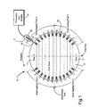
- FIGURE 1 is a cross-sectional view of a synchronous dynamo-electric machine 10 such as, for example, a large turbine-generator, that employs the interaction of magnetic fields in its rotor 12 and stator 14 to produce electric power.
- High alternating current (AC) output power is conventionally generated in the stator armature winding 18 which operates as an armature.
- Field windings 16 of coils on the rotor 12 are conventionally excited by a direct current (DC) field supply.
- the DC field supply is generated either by an external DC exciter generator and fed through slip rings to the rotor field windings, or in a brushless generator-rectifier assembly rotating with the rotor.
- Rotors 12 of large turbine-generators conventionally have two, four or more poles 17 formed by the arrangement of the lateral slots in the rotor that contain the field windings 16 and by interconnecting the windings with end turns.
- a two-pole generator is described herein, although the invention is not limited to two-pole generators.
- the rotor coil windings 16 are symmetrically arranged in the slots with respect to a pole axis 17 and form an annular array around the rotor.
- the flux probe 22 may extend radially through the stator 14 and into the air gap 20.
- the flux probe may be permanently mounted in the stator or may be temporarily inserted into the air gap between the stator and rotor.
- the flux probe senses the rotor field winding slot leakage flux.
- the leakage flux is indicative of the rotor movement and, in particular, the alternating passage of rotor windings and slots across the sensing field of the probe.
- the flux probe produces a voltage that is proportional to the rate of flux change as the rotor turns.
- the flux probe signal is collected by a processor and monitor 24 that may be associated with an instrument monitoring the generator.
- the processor may be on site with the generator or located at a remote location.
- the processor 24 may monitor in real time the voltage level from the flux probe signal record.
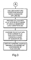
- FIGURES 2 and 3 are charts of process steps for identifying a shorted turn in a field winding of a generator or other synchronous machine.
- flux probe measurements are taken during normal operation of the generator.
- the flux probe signal provides an indication of the magnetic flux around the stator and, particularly, in the annular air gap between the rotor and stator.
- FIGURE 4 is an exemplary chart 31 of flux probe voltage signal 32 verses time, represented by horizontal axis 38.
- the flux probe signal data 32 shows the normal slot leakage voltage reversals of the rotor for one revolution of the rotor.
- the flux probe signal 32 oscillates as the stationary flux probe senses the passage of coil bars in slots (S) and teeth (T) on the rotor.
- the flux probe senses the flux in the air gap 20 due to the coils in each of the poles (P) of the rotor.
- the amplitude of the flux signal 32 during one revolution of the rotor is proportional to the number of active turns in a slot being sensed and the magnitude of the air-gap flux density. Maximum flux density occurs at the leading edge of each pole and progressively decreases toward the quadrature axis of the pole.
- the pattern of flux variation near the field winding is a signature characteristic of each field of a particular rotor and its generator. As the rotor turns, the flux probe senses changes in the magnetic flux field in the air gap around the entire circumference of the rotor.
- the flux probe signal 32 is integrated in real time to yield the flux density data trace 36, in step 37.
- the processor 24 identifies the zero-crossing location in real-time. Further, the processor 24 may record and store the flux probe voltage signal 32 and flux density data 36 collected during certain periods, such as one rotor revolution. The processor may store data on flux and flux density for several one revolution periods corresponding to various changes in the flux density. The processor may also record other related electrical and load information, e.g., generator load, field voltage and field current corresponding to the recorded flux probe voltage levels and flux density data.
- the flux probe and flux density data may be captured when certain events occur (step 44), such as a change in the zero crossing point 40 of the flux density trace.
- the flux density trace crosses the time axis 38 at a zero-crossing point(s) 40.
- a zero crossing point 40 will generally occur during one revolution of the rotor and for each rotor pole 17.
- the zero-crossing points should occur at the same time displacement in each rotor revolution cycle, provided that the load on the generator and coil conditions do not change.
- the cyclical flux probe signal e.g., the flux signal during one rotor revolution
- the flux density trace 36 (which is a function of the integration of the flux probe signal) and the zero-crossing points 40 of density trace should remain unchanged if no shorts develop in the winding turns and the load on the generator remains relatively constant.
- the flux probe signal, and hence the flux density trace and its zero-crossing points, will vary if a short occurs in one of the winding turns or if the load on the generator changes.
- the processor 24 detects changes in the coil condition, e.g., shorts, or changes in the generator load by monitoring the zero-crossing point 40 for changes in the flux density from one rotor revolution to the next.
- the processor 24 monitors the zero-crossing points to detect changes in the timing of the zero-crossing points, in step 44.
- the processor executes an algorithm to detect changes in zero-crossing points 40.
- the algorithm segments the area between the quadrature axis to the pole face into a series of regions that are in number at least twice the number of coils per pole.
- the processor determines in which region the zero crossing 40 occurs, and if the region in which the zero cross has occurred is different than in a preceding revolution. Changes in the region of the zero crossing indicates that the windings have experienced a load change or a possible short. Detecting when the flux density zero crossing shifts from one region to another provides sufficient resolution of zero crossing shifts to identify shorted turns and load changes.
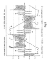
- FIGURES 5 and 6 are charts that show flux probe voltage signal traces 32 and flux density traces 36 for a generator operating at ten percent (10%) load ( Figure 5) and at full (100%) load (Figure 6).
- a comparison of Figures 5 (10% load) and 6 (100% load) shows that a change in the load on the generator alters the flux probe signal 32, the flux density trace 36, and the zero-crossing points 40 of the flux density.
- the coils associated with pole X 33 and pole Y 35 are indicated on the charts.
- a shorted turn in a winding is indicated by flux signal amplitudes 41, 42, 43 for a coil in a slot that is uncharacteristically small in comparison with the signal amplitudes for adjacent slots and the same slot of the opposite pole.
- the shorted turns of Figure 5 correspond to shorts in a particular coil, e.g. (41) coil #8 of pole Y and (42) coil #7 of pole X.
- the shorted turns 43 that appear in Figure 6 correspond to a short in coil #2 of pole Y.
- the flux probe signals shown in Figures 5 and 6 are of the same generator which has shorted turns in six of the eight coils including a three turn short in coil #2 of pole Y (43), a two turn shorts in coil #7 of pole X (42), and a five turn shorts in coil #8 of pole Y (41).
- the number of shorts in a coil is proportional to the reduction in the "sensitized" flux amplitude due to the shorts.
- the shorts in coil #7 (42) and #8 (41) appear in the flux signal when the generator is under low loads as seen in Figure 5 and these shorts do not appear when the generator is operating near full load ( Figure 6).
- the short in coil #2 (43) appears in the flux signal when the generator is operating near full load ( Figure 6) and not when the generator is near low loads ( Figure 5). It is because of this phenomena that data must be collected over a large load swing.
- the processor may be programmed to capture, in step 44, the flux probe data when the zero-crossing point 40 of the flux density trace 36 shifts from one region to another.
- the zero-crossing point 40 of the flux density trace is detected by the processor 24 after it integrates the flux probe signal in real time, during step 39.
- the processor may monitor the timing of the zero-crossing points during each rotor revolution.
- the crossing points 40 should occur at the same time during each revolution, unless the load on the generator changes or a short occurs in a winding.
- the processor may temporarily store data regarding the timing of flux density zero-crossing points for one or more prior rotor revolution(s).
- the processor compares the timing of the zero-crossings for the most current revolution to the zero-crossing timing of one or more revolution periods.
- the processor determines whether the current zero-crossing timing has changed substantially, such as by detecting that the crossing has moved into a different time region. If the zero-crossing has substantially shifted, the processor captures data regarding the flux probe signal data, flux density trace and coil load conditions for the current revolution period, in step 44. This collected data is electronically stored for later analysis by a specialist or for further processing by the processor 24.
- the monitoring of flux data continues during the on-line operation of the generator.
- the processor may detect many changes in the zero-crossing point and capture the flux data each time such a change is detected.
- the detection of a zero-crossing change (and the capturing of flux data) will mostly occur for reasons other than a shorted turn in a coil.
- the zero-crossing point often changes when the coil conditions change, such as when the loading of the generator is varied (both Megawatts and Megavars). Accordingly, much of the flux data captured and stored will not indicate a change in shorted turns.
- Data sufficient to identify a shorted turn is collected by capturing flux data each time the zero-crossing 40 timing changes.
- the flux data is captured regardless of whether the zero-crossing timing change is due to a load change or a shorted coil. Collecting flux data over a wide range of operating loads and over an extended period of on-line operation, should capture flux data sufficient to detect a shorted turn in any coil.
- the processor 24 may be programmed to compare the amplitudes of the coils of the different poles of the flux probe signal in the time regions aligned with the flux density zero crossing.
- the current captured flux data may be flagged by the processor as indicating a possible shorted coil turn in a given pole, if the amplitude of that "sensitized" coil for the captured flux data is substantially lower than the corresponding amplitudes of the other "sensitized” coil for the other pole or poles. This flagging of captured flux data may assist a specialist to quickly identify a shorted turn. Flagged flux data may thus be evaluated soon after it occurs and while the generator continues to operate on-line without any special intervention.
- a specialist may periodically review the collected data taken upon changes in the zero-crossings 40 to determine whether a short has occurred in the windings, in step 45.
- the processor may generate a report of flagged flux data (see step 46) that may indicate a short or may generate a report when the flux data has been collected at all of the load conditions needed for a shorted turn analysis.
- the specialist may review the collected flux probe data to determine, in step 48, whether data has been recently collected for sufficient generator operating conditions to evaluate the flux data for shorted turns.
- the flux data should be collect for every time-region that the flux density moves into.
- the processor may report, in step 50, to the specialist the times and dates at which the flux load data has been collected for each of zero-crossing excursions.
- the specialist reviews the collected flux probe data and flux density traces to determine whether a short circuit exists in any of the coils, in step 50.
- the analysis may require the specialist to compare the current data of flux and flux density with historic flux and flux density data taken on the same generator at similar operating loads.
- the historic data may be taken at a time when it is known that there are no shorted winding turns. This historic data may be electronically saved as flux signature plots for each of several generator operating loads.
- the flux signature plots are obtained by a specialist for selected generator load conditions, in step 52.
- the specialist may compare the amplitude of the flux signal for a coil suspected of having a short with the flux amplitude of a similar coil in another pole.
- the flux amplitudes of the coils being compared are amplitudes taken from the same rotor revolution.
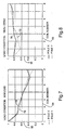
- the flux data shown in Figures 7 and 8 are examples of signature plots of flux probe data.
- the signature plots each correspond to a different generator operating load.
- Figure 7 presents flux data at a minimum (10%) generator operating load and
- Figure 8 presents flux data at a 100% generator speed with no load.
- Each signature plot shows the normalized flux magnitude 70, 72 of all coils corresponding to each rotor pole.
- the flux magnitude 70 at pole X is superimposed on the flux magnitude 72 for pole Y.
- the signature plots are generated using the flux data from a revolution of the rotor, such as shown in Figures 5 and 6.
- Similar flux magnitude versus coil number plots for each pole may be prepared from current flux data such as shown in Figures 5 and 6.
- a specialist can detect a short in a winding turn by comparing current flux and flux density data to a signature plot or other historical flux and flux density data for several generator load conditions, in step 58.
- the specialist compares the flux and flux density data from a reduced set of zero-crossing locations corresponding to twice the number coils for any given pole. Moreover, this comparison of data may be performed while the generator is on-line, as it can be accomplished using data captured by the processor and stored electronically.
- the comparison of flux data and the analysis to detect shorted turns may be conducted without taking the generator off-line, if sufficient flux data has been collected to perform the analysis during the on-line collection of flux data when a shift in the zero-crossing point is detected.
- Generators often go through unplanned load reductions and even trip events, and the additional data corresponding to the off-line conditions can be automatically collected during that process.
- a predetermined period, e.g., one month, of generator operation may be sufficient to collect enough flux data to properly detect shorts in coil turns. Because all or most of the data needed to detect shorts may be collected during normal operation, the need for scheduled outages or disruption of routine operation of the machine is minimized.
Landscapes
- Physics & Mathematics (AREA)
- General Physics & Mathematics (AREA)
- Tests Of Circuit Breakers, Generators, And Electric Motors (AREA)
- Control Of Eletrric Generators (AREA)
Description
- The present invention relates to the detection of electrical shorts in synchronous machine field windings and, in particular, to the detection of electrical shorts in the winding turns of a generator.
- The field windings in the rotor of a generator are generally an annular array of conductive coil bars arranged in slots around the outer periphery of the rotor. The coil bars extend longitudinally along the length of the rotor and are connected by end turns at each end of the rotor. A connected pair of coil bars and end turns form a coil winding turn.
- Several coil winding turns are arranged on a rotor to form a pole. A rotor may have multiple poles, e.g. two or four poles. An exciter circuit applies DC (direct current) to the coils bars of the rotor. The insulation separating the conductor bars or end turns of a rotor of the above type may break down and cause a shorted circuit across one or more coils of the winding. These short circuits in the coil windings are collectively referred to as shorted turns.
- A coil winding short can cause a variety of overheating conditions and related vibration problems. Identification of shorted turns in a timely and cost-effective manner is desirable to reduce the off-line downtime period needed to repair shorts in the coil windings of the generator. A flux probe sensor is introduced in the air-gap. The sensor generates a signal proportional to the rate of change of the electromagnetic flux in the air-gap.
- ln conventional practice, shorted turns are identified and trended by performing periodic (annual or bi-annual) tests on the generator field coil windings. These tests are conducted by trained specialists who connect an analyzer, having a processor and monitor, to the flux probe and to a once per revolution output of the generator. The flux probe data may be collected at different generator load points, typically at the load points of: open circuit, 10%, 20%, 30%, 40%, 50%, 60%, 70%, 80%, 90%, 100% and full-speed no load all with zero Mega-Volt-Amperes-Reactive (MVARS), e.g., no reactive power. The load changes are necessary because different coils are "sensitized" at different load points. Analysis of the coils when they are each "sensitized" provides a more accurate shorted turn analysis of the coils, than is generally achieved by analysis of the coils when they are not "sensitized".
- In the past, obtaining a comprehensive shorted turn analysis has often required that generator load changes be made and such load changes require extensive coordination between the test specialist and the load dispatcher. In some cases, it may be necessary to take the generator unit off-line to obtain data corresponding to the higher numbered coils in the rotor.
- A disadvantage of a conventional shorted turn analysis is that a specialized testing sequence is followed when the generator is being operated suboptimally. This sequence requires extensive coordination between the test specialist and the load dispatcher including taking the generator off-line. The shorted turn detection process may involve inefficient use of the generator while the generator is tested at the various load conditions needed to collect flux data while each of the coils are sensitized. Accordingly, there is a long-standing but previously unmet need for a testing technique to locate turn shorts in a generator field winding, which does not require lengthy testing of a generator outside its normal operating envelope.
-
EP 0608442 describes a rotor winding short circuit detector. A detection winding detects a succession of pulse trains relating to variations in magnetic flux distribution. Differences between sequences of pulse trains are used to detect short circuits. -
US 4506218 discloses a condition sensing arrangement for AC machines. A Hall switch is used to detect field strength decreases as a result of overload. - Circuitry responsive to the absence of periodic pulses actuates an indicator circuit to warn of the faulty operation.
- According to a first aspect, the invention provides a method for detecting a shorted turn in a synchronous machine having a rotor using a magnetic flux probe, said method comprising:
- a. monitoring a signal from the flux probe during on-line operation of the machine;
- b. integrating the flux probe signal to generate a flux density data trace for a rotor revolution including when the flux density trace has a zero value ;
- c. upon detecting a variation between a current flux density trace zero value and a prior flux density trace zero value, capturing the flux probe signal for a current rotor revolution;
- d. repeating steps (a) through (c) as the on-line operation progresses through various machine load conditions; and
- e. performing a shorted turn analysis with the captured flux signal data
- Embodiments of the invention will now be described, by way of example, with reference to the accompanying drawings, in which:
- FIGURE 1 is a cross-sectional diagram of a conventional 2-pole generator having a stator winding, a rotor winding and a flux probe in-place.
- FIGURES 2 and 3 are flow charts showing exemplary steps for detecting a shorted turn in a field winding.
- FIGURES 4, 5 and 6 are exemplary charts of a flux probe signal and flux density traces.
- FIGURES 7 and 8 are exemplary flux data signature plots.
- A new testing procedure has been developed to locate a short in a generator field winding, such as the winding shown in FIGURE 1. The testing procedure employs a standard
magnetic flux probe 22, which may be a conventional temporary or permanently fixed probe that is already installed or is installable in agenerator stator 14. Data from theflux probe 22 is automatically collected while the generator is on-line and producing electrical power for a public utility, for example. The collected data is stored for later use in identifying shorts in the coils of the generator field winding. - The continuous and automatic data acquisition system described herein, performs data acquisition regarding shorted turns. Reduction and analysis of the data is triggered based on the locations of the flux density zero-crossings. Automating the collection of magnetic flux data from an operating, on-line generator should reduce generator off-line periods and provide a convenient and cost efficient process to detect shorts in the end turns of generator field windings. An on-
line monitor 24 of captured flux data can be reviewed remotely by a specialist to detect shorted turns, or the monitor can operate autonomously and may be periodically reviewed to evaluate the health of the generator. - FIGURE 1 is a cross-sectional view of a synchronous dynamo-
electric machine 10 such as, for example, a large turbine-generator, that employs the interaction of magnetic fields in itsrotor 12 andstator 14 to produce electric power. High alternating current (AC) output power is conventionally generated in the stator armature winding 18 which operates as an armature.Field windings 16 of coils on therotor 12 are conventionally excited by a direct current (DC) field supply. The DC field supply is generated either by an external DC exciter generator and fed through slip rings to the rotor field windings, or in a brushless generator-rectifier assembly rotating with the rotor. -
Rotors 12 of large turbine-generators conventionally have two, four ormore poles 17 formed by the arrangement of the lateral slots in the rotor that contain thefield windings 16 and by interconnecting the windings with end turns. For purposes of illustration, a two-pole generator is described herein, although the invention is not limited to two-pole generators. Therotor coil windings 16 are symmetrically arranged in the slots with respect to apole axis 17 and form an annular array around the rotor. - An
annular gap 20, conventionally referred to as an air-gap, separates therotor windings 16 from thearmature windings 18 of the stator. Theflux probe 22 may extend radially through thestator 14 and into theair gap 20. The flux probe may be permanently mounted in the stator or may be temporarily inserted into the air gap between the stator and rotor. The flux probe senses the rotor field winding slot leakage flux. The leakage flux is indicative of the rotor movement and, in particular, the alternating passage of rotor windings and slots across the sensing field of the probe. The flux probe produces a voltage that is proportional to the rate of flux change as the rotor turns. - The flux probe signal is collected by a processor and
monitor 24 that may be associated with an instrument monitoring the generator. The processor may be on site with the generator or located at a remote location. Theprocessor 24 may monitor in real time the voltage level from the flux probe signal record. - FIGURES 2 and 3 are charts of process steps for identifying a shorted turn in a field winding of a generator or other synchronous machine. In step 30, flux probe measurements are taken during normal operation of the generator. The flux probe signal provides an indication of the magnetic flux around the stator and, particularly, in the annular air gap between the rotor and stator.
- FIGURE 4 is an
exemplary chart 31 of fluxprobe voltage signal 32 verses time, represented byhorizontal axis 38. The fluxprobe signal data 32 shows the normal slot leakage voltage reversals of the rotor for one revolution of the rotor. Theflux probe signal 32 oscillates as the stationary flux probe senses the passage of coil bars in slots (S) and teeth (T) on the rotor. During onerevolution 34 of the rotor, the flux probe senses the flux in theair gap 20 due to the coils in each of the poles (P) of the rotor. - The amplitude of the
flux signal 32 during one revolution of the rotor is proportional to the number of active turns in a slot being sensed and the magnitude of the air-gap flux density. Maximum flux density occurs at the leading edge of each pole and progressively decreases toward the quadrature axis of the pole. The pattern of flux variation near the field winding is a signature characteristic of each field of a particular rotor and its generator. As the rotor turns, the flux probe senses changes in the magnetic flux field in the air gap around the entire circumference of the rotor. - The
flux probe signal 32 is integrated in real time to yield the flux density data trace 36, in step 37. Theprocessor 24 identifies the zero-crossing location in real-time. Further, theprocessor 24 may record and store the fluxprobe voltage signal 32 andflux density data 36 collected during certain periods, such as one rotor revolution. The processor may store data on flux and flux density for several one revolution periods corresponding to various changes in the flux density. The processor may also record other related electrical and load information, e.g., generator load, field voltage and field current corresponding to the recorded flux probe voltage levels and flux density data. - The flux probe and flux density data may be captured when certain events occur (step 44), such as a change in the zero
crossing point 40 of the flux density trace. The flux density trace crosses thetime axis 38 at a zero-crossing point(s) 40. A zerocrossing point 40 will generally occur during one revolution of the rotor and for eachrotor pole 17. The zero-crossing points should occur at the same time displacement in each rotor revolution cycle, provided that the load on the generator and coil conditions do not change. - During normal generator operation the cyclical flux probe signal, e.g., the flux signal during one rotor revolution, should be largely unchanged, assuming that no shorts develop in the winding turns and the operating load of the generator remains constant. Similarly, the flux density trace 36 (which is a function of the integration of the flux probe signal) and the zero-
crossing points 40 of density trace should remain unchanged if no shorts develop in the winding turns and the load on the generator remains relatively constant. The flux probe signal, and hence the flux density trace and its zero-crossing points, will vary if a short occurs in one of the winding turns or if the load on the generator changes. - The
processor 24 detects changes in the coil condition, e.g., shorts, or changes in the generator load by monitoring the zero-crossing point 40 for changes in the flux density from one rotor revolution to the next. Theprocessor 24 monitors the zero-crossing points to detect changes in the timing of the zero-crossing points, instep 44. The processor executes an algorithm to detect changes in zero-crossing points 40. The algorithm segments the area between the quadrature axis to the pole face into a series of regions that are in number at least twice the number of coils per pole. The processor then determines in which region the zerocrossing 40 occurs, and if the region in which the zero cross has occurred is different than in a preceding revolution. Changes in the region of the zero crossing indicates that the windings have experienced a load change or a possible short. Detecting when the flux density zero crossing shifts from one region to another provides sufficient resolution of zero crossing shifts to identify shorted turns and load changes. - FIGURES 5 and 6 are charts that show flux probe voltage signal traces 32 and flux density traces 36 for a generator operating at ten percent (10%) load (Figure 5) and at full (100%) load (Figure 6). A comparison of Figures 5 (10% load) and 6 (100% load) shows that a change in the load on the generator alters the
flux probe signal 32, theflux density trace 36, and the zero-crossing points 40 of the flux density. The coils associated with pole X 33 andpole Y 35 are indicated on the charts. A shorted turn in a winding is indicated byflux signal amplitudes aberrations - An aberration in the flux field due to a shorted turn does not appear during all operating conditions of the generator. The shorted turns of Figure 5 (see flux signals at 41, 42) correspond to shorts in a particular coil, e.g. (41)
coil # 8 of pole Y and (42)coil # 7 of pole X. The shorted turns 43 that appear in Figure 6 correspond to a short incoil # 2 of pole Y. The flux probe signals shown in Figures 5 and 6 are of the same generator which has shorted turns in six of the eight coils including a three turn short incoil # 2 of pole Y (43), a two turn shorts incoil # 7 of pole X (42), and a five turn shorts incoil # 8 of pole Y (41). The number of shorts in a coil is proportional to the reduction in the "sensitized" flux amplitude due to the shorts. The shorts in coil #7 (42) and #8 (41) appear in the flux signal when the generator is under low loads as seen in Figure 5 and these shorts do not appear when the generator is operating near full load (Figure 6). The short in coil #2 (43) appears in the flux signal when the generator is operating near full load (Figure 6) and not when the generator is near low loads (Figure 5). It is because of this phenomena that data must be collected over a large load swing. - Collecting all of the flux probe data during the entire time of generator operation may result in the storage of excessive amounts of data and excessive data for a specialist to readily review. To reduce the amount of data stored and to cull the amount of redundant flux data to be reviewed by a technician, the processor may be programmed to capture, in
step 44, the flux probe data when the zero-crossing point 40 of theflux density trace 36 shifts from one region to another. - The zero-
crossing point 40 of the flux density trace is detected by theprocessor 24 after it integrates the flux probe signal in real time, duringstep 39. To detect a shift in the zero-crossing point, the processor may monitor the timing of the zero-crossing points during each rotor revolution. The crossing points 40 should occur at the same time during each revolution, unless the load on the generator changes or a short occurs in a winding. The processor may temporarily store data regarding the timing of flux density zero-crossing points for one or more prior rotor revolution(s). - As the flux density zero-crossing point is determined for each successive rotor revolution period, the processor compares the timing of the zero-crossings for the most current revolution to the zero-crossing timing of one or more revolution periods. The processor determines whether the current zero-crossing timing has changed substantially, such as by detecting that the crossing has moved into a different time region. If the zero-crossing has substantially shifted, the processor captures data regarding the flux probe signal data, flux density trace and coil load conditions for the current revolution period, in
step 44. This collected data is electronically stored for later analysis by a specialist or for further processing by theprocessor 24. - The monitoring of flux data, detecting changes in the flux density zero-crossing point and capturing data when the zero-crossing point changes, continues during the on-line operation of the generator. The processor may detect many changes in the zero-crossing point and capture the flux data each time such a change is detected. The detection of a zero-crossing change (and the capturing of flux data) will mostly occur for reasons other than a shorted turn in a coil. The zero-crossing point often changes when the coil conditions change, such as when the loading of the generator is varied (both Megawatts and Megavars). Accordingly, much of the flux data captured and stored will not indicate a change in shorted turns.
- Data sufficient to identify a shorted turn is collected by capturing flux data each time the zero-crossing 40 timing changes. The flux data is captured regardless of whether the zero-crossing timing change is due to a load change or a shorted coil. Collecting flux data over a wide range of operating loads and over an extended period of on-line operation, should capture flux data sufficient to detect a shorted turn in any coil.
- Much of the captured flux data will represent data captured solely because the load on the generator changed and will not indicate a shorted turn. The amount of collected data should not be excessive and can be readily reviewed by a specialist searching for shorted turns. In
step 45, theprocessor 24 may be programmed to compare the amplitudes of the coils of the different poles of the flux probe signal in the time regions aligned with the flux density zero crossing. The current captured flux data may be flagged by the processor as indicating a possible shorted coil turn in a given pole, if the amplitude of that "sensitized" coil for the captured flux data is substantially lower than the corresponding amplitudes of the other "sensitized" coil for the other pole or poles. This flagging of captured flux data may assist a specialist to quickly identify a shorted turn. Flagged flux data may thus be evaluated soon after it occurs and while the generator continues to operate on-line without any special intervention. - A specialist may periodically review the collected data taken upon changes in the zero-
crossings 40 to determine whether a short has occurred in the windings, instep 45. The processor may generate a report of flagged flux data (see step 46) that may indicate a short or may generate a report when the flux data has been collected at all of the load conditions needed for a shorted turn analysis. The specialist may review the collected flux probe data to determine, instep 48, whether data has been recently collected for sufficient generator operating conditions to evaluate the flux data for shorted turns. The flux data should be collect for every time-region that the flux density moves into. In addition, the processor may report, instep 50, to the specialist the times and dates at which the flux load data has been collected for each of zero-crossing excursions. - When the operator has current data from the flux probe signals for all generator load conditions or flux data from load conditions sufficient to conduct a shorted turn analysis, the specialist reviews the collected flux probe data and flux density traces to determine whether a short circuit exists in any of the coils, in
step 50. The analysis may require the specialist to compare the current data of flux and flux density with historic flux and flux density data taken on the same generator at similar operating loads. The historic data may be taken at a time when it is known that there are no shorted winding turns. This historic data may be electronically saved as flux signature plots for each of several generator operating loads. The flux signature plots are obtained by a specialist for selected generator load conditions, in step 52. Alternatively, the specialist may compare the amplitude of the flux signal for a coil suspected of having a short with the flux amplitude of a similar coil in another pole. The flux amplitudes of the coils being compared are amplitudes taken from the same rotor revolution. - The flux data shown in Figures 7 and 8 are examples of signature plots of flux probe data. The signature plots each correspond to a different generator operating load. Figure 7 presents flux data at a minimum (10%) generator operating load and Figure 8 presents flux data at a 100% generator speed with no load. Each signature plot shows the normalized
flux magnitude flux magnitude 70 at pole X is superimposed on theflux magnitude 72 for pole Y. The signature plots are generated using the flux data from a revolution of the rotor, such as shown in Figures 5 and 6. Similar flux magnitude versus coil number plots for each pole (as are shown in Figures 7 and 8) may be prepared from current flux data such as shown in Figures 5 and 6. - By comparing the current signature plot to a previous signature plot, shorted turns in the coils of a pole may be readily identified, in step 56. A specialist can detect a short in a winding turn by comparing current flux and flux density data to a signature plot or other historical flux and flux density data for several generator load conditions, in step 58. The specialist compares the flux and flux density data from a reduced set of zero-crossing locations corresponding to twice the number coils for any given pole. Moreover, this comparison of data may be performed while the generator is on-line, as it can be accomplished using data captured by the processor and stored electronically.
- The comparison of flux data and the analysis to detect shorted turns may be conducted without taking the generator off-line, if sufficient flux data has been collected to perform the analysis during the on-line collection of flux data when a shift in the zero-crossing point is detected. Generators often go through unplanned load reductions and even trip events, and the additional data corresponding to the off-line conditions can be automatically collected during that process. A predetermined period, e.g., one month, of generator operation may be sufficient to collect enough flux data to properly detect shorts in coil turns. Because all or most of the data needed to detect shorts may be collected during normal operation, the need for scheduled outages or disruption of routine operation of the machine is minimized.
Claims (14)
- A method for detecting a shorted turn in a synchronous machine (10) having a rotor (12) using a magnetic flux probe (22), said method comprising:a. monitoring (30) a signal (32) from the flux probe during on-line operation of the machine;b. integrating (37) the flux probe signal to generate a flux density data trace (36) for a rotor revolution including when the flux density trace has a zero value (40,44);c. upon detecting (44) a variation between a current flux density trace (36) zero value (40,44) and a prior flux density trace zero value, capturing the flux probe signal for a current rotor revolution (34);d. repeating steps (a) through(c) as the on-line operation progresses through various machine load conditions (48); ande. performing a shorted turn analysis (54, 56) with the captured flux signal data.
- A method as in claim 1 wherein the flux probe data is integrated (37) in real time.
- A method as in claim 1 wherein steps (c) and (d) are performed to capture the flux probe data while each of the individual coils in the rotor are sensitized.
- A method as in claim 3 wherein an amplitude reduction for a sensitized coil in the flux probe is detected based on a variation in a timing of when the flux density trace has a predetermined zero value (40, 44) during each rotor revolution (34).
- A method as in claim 1 wherein the variation in the flux density trace is a variation in a timing of when the flux density trace has a zero value (40, 44) during each rotor revolution (34).
- A method as in claim 1 wherein the variation in flux density trace is a variation in a timing of when the flux density trace has a zero value (40, 44) and the variation occurs between successive rotor revolutions.
- A method as in claim 1 wherein the variation in the flux density trace occurs between the flux density trace for a current rotor revolution and the flux density trace for a preceding rotor revolution (52).
- A synchronous machine (10) comprising:a rotor (12) containing a plurality of field windings (16);a stator (14) containing armature windings (18) separated from the field windings (16) by an air gap (20), wherein the stator (14) houses a flux probe (22); anda processor (24) operably coupled to the flux probe (22), wherein the processor is further operable to:a monitor a signal (32) from the flux probe (22) during on-line operation of the machine (10);b. integrate (37) the flux probe signal to generate a flux density data trace (36) for a rotor revolution including when the flux density trace has a zero value (40,44);c. detect a variation between a current flux density trace (36) zero value (40,44) and a prior flux density trace zero value and capture the flux probe signal for a current rotor revolution (34);d. repeat steps a) through c) as the on-line operation progresses through various machine load conditions (48); ande. perform a shorted turn analysis (54, 56) with the captured flux signal data.
- The synchronous machine (10) of claim 8, wherein the processor (24) is further operable to integrate the flux probe data in real time.
- The synchronous machine (10) of claim 8, wherein the processor (24) is operable to perform steps c) and d) to capture the flux probe data while each of the individual coils in the rotor (12) are sensitized.
- The synchronous machine (10) of claim 10, wherein the processor (24) is operable to detect an amplitude reduction for a sensitized coil in the flux probe based on a variation in timing of when the flux density trace has a predetermined zero value (40,44) during each rotor revolution (34).
- The synchronous machine (10) of claim 8, wherein the variation in the flux density trace is a variation in a timing of when the flux density trace has a zero value (40,44) during each rotor revolution (34).
- The synchronous machine (10) of claim 8, wherein the variation in flux density trace is a variation in a timing of when the flux density trace has a zero value (40,44) and the , variation occurs between successive rotor revolutions.
- The synchronous machine (10) of claim 8, wherein the variation in the flux density trace occurs between the flux density trace for a current rotor revolution and the flux density trace for a preceding rotor revolution (52).
Applications Claiming Priority (2)
| Application Number | Priority Date | Filing Date | Title |
|---|---|---|---|
| US401600 | 1989-08-31 | ||
| US10/401,600 US6911838B2 (en) | 2003-03-31 | 2003-03-31 | Online detection of shorted turns in a generator field winding |
Publications (2)
| Publication Number | Publication Date |
|---|---|
| EP1464974A1 EP1464974A1 (en) | 2004-10-06 |
| EP1464974B1 true EP1464974B1 (en) | 2007-08-15 |
Family
ID=32850550
Family Applications (1)
| Application Number | Title | Priority Date | Filing Date |
|---|---|---|---|
| EP04251896A Expired - Lifetime EP1464974B1 (en) | 2003-03-31 | 2004-03-30 | Online detection of shorted turns in a generator field winding |
Country Status (4)
| Country | Link |
|---|---|
| US (1) | US6911838B2 (en) |
| EP (1) | EP1464974B1 (en) |
| JP (1) | JP4371262B2 (en) |
| DE (1) | DE602004008132T2 (en) |
Families Citing this family (23)
| Publication number | Priority date | Publication date | Assignee | Title |
|---|---|---|---|---|
| US7259583B2 (en) * | 2004-07-23 | 2007-08-21 | General Electric Company | Methods and apparatus for testing power generators |
| US7282923B2 (en) * | 2005-09-20 | 2007-10-16 | General Electric Company | Systems and methods for triggering a partial discharge acquisition |
| US7411404B2 (en) * | 2006-12-08 | 2008-08-12 | General Electric Company | Apparatus, system, and method for detecting an electrical short condition in a dynamoelectric machine |
| US8019561B1 (en) | 2007-09-03 | 2011-09-13 | Veric Systems Llc | Electrical short locator method |
| US20090067101A1 (en) * | 2007-09-06 | 2009-03-12 | Siemens Power Generation, Inc. | Method and System for Limiting a Current in an Alternating Current Generator |
| US20090219030A1 (en) * | 2008-02-29 | 2009-09-03 | General Electric Company | Methods and Systems for Detecting Rotor Field Ground Faults In Rotating Machinery |
| ZA200903757B (en) * | 2008-07-29 | 2010-04-28 | Eskom Holdings Pty Ltd | Stray-flux detection and analysis system |
| TWI391685B (en) * | 2009-10-16 | 2013-04-01 | Ind Tech Res Inst | Station for detecting winding products and method for detecting inter-turn short-circuit |
| US8781765B2 (en) * | 2011-04-11 | 2014-07-15 | General Electric Company | Online monitoring system and method to identify shorted turns in a field winding of a rotor |
| CN102565703A (en) * | 2011-06-17 | 2012-07-11 | 江苏省电力公司 | Method for on-line recognizing and obtaining characteristic parameters of direct-drive permanent magnet synchronous wind turbine |
| US8903664B2 (en) * | 2011-06-22 | 2014-12-02 | General Electric Company | System and method for use in monitoring synchronous machines |
| CN102636751A (en) * | 2012-04-26 | 2012-08-15 | 中国人民解放军海军工程大学 | Alternating-current brushless generator fault detection method based on exciter exciting current |
| EP2746795B1 (en) * | 2012-12-20 | 2015-10-07 | Alstom Technology Ltd | Device and method for measuring the magnetic field in the air-gap of an electric machine |
| US8978239B2 (en) | 2013-01-09 | 2015-03-17 | General Electric Company | Field coil winding assembly |
| CO7050216A1 (en) | 2013-03-05 | 2014-09-10 | Univ Nac De Colombia | Method and system for the detection and diagnosis of failures of electrical machines in operation |
| FR3003102B1 (en) * | 2013-03-05 | 2015-04-17 | Electricite De France | METHOD FOR DETECTING A FAULT OF ROTOR EXCENTRICITY OF A ROTATING ELECTRIC MACHINE |
| CN103792463B (en) * | 2014-02-25 | 2017-02-01 | 华北电力大学(保定) | Steam-turbine generator rotor winding short trouble diagnosis method based on fictitious power principle |
| JP7021130B2 (en) * | 2019-01-16 | 2022-02-16 | ファナック株式会社 | Short circuit detection device, motor control device and numerical control system that detect the interlayer short circuit of the windings in the motor. |
| DE112019007006T5 (en) * | 2019-03-12 | 2021-12-02 | Mitsubishi Electric Corporation | SHORT-CIRCUIT DETECTION DEVICE AND SHORT-CIRCUIT DETECTION METHOD |
| JP6725765B1 (en) * | 2019-04-12 | 2020-07-22 | 三菱電機株式会社 | Short circuit detection device and short circuit detection method |
| CN110297183B (en) * | 2019-07-17 | 2021-05-11 | 国网江苏省电力有限公司电力科学研究院 | Method and device for diagnosing turn-to-turn short circuit fault of rotor of synchronous phase modulator and storage medium |
| CN113776421A (en) * | 2021-08-26 | 2021-12-10 | 北京四方继保工程技术有限公司 | Transformer winding deformation diagnosis method and system |
| CN114884280B (en) * | 2022-04-28 | 2023-07-04 | 东方电气集团东方电机有限公司 | Rotor coil temperature measuring device |
Family Cites Families (8)
| Publication number | Priority date | Publication date | Assignee | Title |
|---|---|---|---|---|
| US3506914A (en) * | 1968-07-01 | 1970-04-14 | Gen Electric | Method and apparatus for detecting rotor flux variations in the air gap of a dynamoelectric machine |
| US4136312A (en) * | 1976-12-30 | 1979-01-23 | Westinghouse Electric Corp. | Method and apparatus for detection of rotor faults in dynamoelectric machines |
| JPS5683223A (en) * | 1979-12-12 | 1981-07-07 | Hitachi Ltd | Rotary electric machine rotor winding malfunction detector |
| US4506218A (en) * | 1981-01-12 | 1985-03-19 | Rotron Incorporated | Condition sensing arrangement for ac machines |
| US4667148A (en) * | 1985-06-26 | 1987-05-19 | General Electric Company | Generator air-gap flux probe for detecting shorted rotor turns |
| JPH0687642B2 (en) * | 1986-12-15 | 1994-11-02 | 株式会社日立製作所 | Rotor winding abnormality diagnosis device for rotating electric machine |
| US5252915A (en) * | 1992-01-23 | 1993-10-12 | Ontario Hydro | Method and apparatus for detecting stator faults in rotary dynamoelectric machines |
| DE69226532D1 (en) * | 1992-12-30 | 1998-09-10 | Ansaldo Energia Spa | Rotor short circuit detector |
-
2003
- 2003-03-31 US US10/401,600 patent/US6911838B2/en not_active Expired - Fee Related
-
2004
- 2004-03-30 EP EP04251896A patent/EP1464974B1/en not_active Expired - Lifetime
- 2004-03-30 DE DE602004008132T patent/DE602004008132T2/en not_active Expired - Lifetime
- 2004-03-31 JP JP2004103589A patent/JP4371262B2/en not_active Expired - Fee Related
Non-Patent Citations (1)
| Title |
|---|
| None * |
Also Published As
| Publication number | Publication date |
|---|---|
| US6911838B2 (en) | 2005-06-28 |
| JP4371262B2 (en) | 2009-11-25 |
| EP1464974A1 (en) | 2004-10-06 |
| US20040189279A1 (en) | 2004-09-30 |
| DE602004008132T2 (en) | 2008-05-08 |
| DE602004008132D1 (en) | 2007-09-27 |
| JP2004304999A (en) | 2004-10-28 |
Similar Documents
| Publication | Publication Date | Title |
|---|---|---|
| EP1464974B1 (en) | Online detection of shorted turns in a generator field winding | |
| Mehala et al. | Motor current signature analysis and its applications in induction motor fault diagnosis | |
| US8781765B2 (en) | Online monitoring system and method to identify shorted turns in a field winding of a rotor | |
| US5739698A (en) | Machine fault detection using slot pass frequency flux measurements | |
| CN103823150B (en) | Turbo generator rotor interturn short circuit fault diagnosis method of multi sensor joint | |
| US4808932A (en) | Rotor fault and location detector for induction motors | |
| EP2728367B1 (en) | A method for detecting a fault condition in an electrical machine | |
| US7042229B2 (en) | System and method for on line monitoring of insulation condition for DC machines | |
| CN103926506B (en) | Based on the rotor of steam turbo generator Winding Short Fault Diagnosis method of constructor | |
| EP2149980B1 (en) | Stray flux processing method and system | |
| JP2005538370A (en) | Method and apparatus for capturing vibration of a shaft assembly in an electric machine | |
| US20050218906A1 (en) | System and method for monitoring of insulation condition | |
| EP1418655A2 (en) | Speed sensitive field ground detection mode for a generator field winding | |
| Zamudio-Ramírez et al. | Smart sensor for fault detection in induction motors based on the combined analysis of stray-flux and current signals: A flexible, robust approach | |
| CN103792463A (en) | Steam-turbine generator rotor winding short trouble diagnosis method based on fictitious power principle | |
| US9383413B2 (en) | Method of processing recurrent surge oscillograph data to enable more precise location of generator rotor inter-turn shorts and ground faults | |
| Goktas et al. | Separation of induction motor rotor faults and low frequency load oscillations through the radial leakage flux | |
| KR19980084275A (en) | Motor abnormal condition monitoring system through signal analysis of power supply line | |
| CN111983419A (en) | Method and system for detecting a multiphase brushless exciter rectifier diode fault | |
| Sasic et al. | Flux monitoring improvement | |
| Yazici et al. | An adaptive, on-line, statistical method for detection of broken bars in motors using stator current and torque estimation | |
| Swana et al. | Fault diagnosis on a wound rotor induction generator using probabilistic intelligence | |
| Ployard et al. | Detection of rotor faults in salient pole generator using flux density monitoring | |
| He et al. | Online Diagnosis Method for Rotor Inter-turn Short Fault of Hydrogenerator Based on Air Gap Magnetic Field Decoupling | |
| Sasic et al. | Flux monitoring improvements for on-line condition monitoring of turbine generator rotors |
Legal Events
| Date | Code | Title | Description |
|---|---|---|---|
| PUAI | Public reference made under article 153(3) epc to a published international application that has entered the european phase |
Free format text: ORIGINAL CODE: 0009012 |
|
| AK | Designated contracting states |
Kind code of ref document: A1 Designated state(s): AT BE BG CH CY CZ DE DK EE ES FI FR GB GR HU IE IT LI LU MC NL PL PT RO SE SI SK TR |
|
| AX | Request for extension of the european patent |
Extension state: AL HR LT LV MK |
|
| 17P | Request for examination filed |
Effective date: 20050406 |
|
| AKX | Designation fees paid |
Designated state(s): CH DE GB LI |
|
| GRAP | Despatch of communication of intention to grant a patent |
Free format text: ORIGINAL CODE: EPIDOSNIGR1 |
|
| GRAS | Grant fee paid |
Free format text: ORIGINAL CODE: EPIDOSNIGR3 |
|
| GRAA | (expected) grant |
Free format text: ORIGINAL CODE: 0009210 |
|
| AK | Designated contracting states |
Kind code of ref document: B1 Designated state(s): CH DE GB LI |
|
| REG | Reference to a national code |
Ref country code: GB Ref legal event code: FG4D |
|
| REG | Reference to a national code |
Ref country code: CH Ref legal event code: EP |
|
| REF | Corresponds to: |
Ref document number: 602004008132 Country of ref document: DE Date of ref document: 20070927 Kind code of ref document: P |
|
| REG | Reference to a national code |
Ref country code: CH Ref legal event code: NV Representative=s name: SERVOPATENT GMBH |
|
| REG | Reference to a national code |
Ref country code: CH Ref legal event code: PFA Owner name: GENERAL ELECTRIC COMPANY Free format text: GENERAL ELECTRIC COMPANY#1 RIVER ROAD#SCHENECTADY, NY 12345 (US) -TRANSFER TO- GENERAL ELECTRIC COMPANY#1 RIVER ROAD#SCHENECTADY, NY 12345 (US) |
|
| PLBE | No opposition filed within time limit |
Free format text: ORIGINAL CODE: 0009261 |
|
| STAA | Information on the status of an ep patent application or granted ep patent |
Free format text: STATUS: NO OPPOSITION FILED WITHIN TIME LIMIT |
|
| 26N | No opposition filed |
Effective date: 20080516 |
|
| PGFP | Annual fee paid to national office [announced via postgrant information from national office to epo] |
Ref country code: CH Payment date: 20130325 Year of fee payment: 10 Ref country code: DE Payment date: 20130327 Year of fee payment: 10 Ref country code: GB Payment date: 20130327 Year of fee payment: 10 |
|
| REG | Reference to a national code |
Ref country code: DE Ref legal event code: R119 Ref document number: 602004008132 Country of ref document: DE |
|
| REG | Reference to a national code |
Ref country code: CH Ref legal event code: PL |
|
| GBPC | Gb: european patent ceased through non-payment of renewal fee |
Effective date: 20140330 |
|
| REG | Reference to a national code |
Ref country code: DE Ref legal event code: R119 Ref document number: 602004008132 Country of ref document: DE Effective date: 20141001 |
|
| PG25 | Lapsed in a contracting state [announced via postgrant information from national office to epo] |
Ref country code: CH Free format text: LAPSE BECAUSE OF NON-PAYMENT OF DUE FEES Effective date: 20140331 Ref country code: GB Free format text: LAPSE BECAUSE OF NON-PAYMENT OF DUE FEES Effective date: 20140330 Ref country code: LI Free format text: LAPSE BECAUSE OF NON-PAYMENT OF DUE FEES Effective date: 20140331 Ref country code: DE Free format text: LAPSE BECAUSE OF NON-PAYMENT OF DUE FEES Effective date: 20141001 |