EP1464839A1 - Hybrid compressor - Google Patents
Hybrid compressor Download PDFInfo
- Publication number
- EP1464839A1 EP1464839A1 EP04007456A EP04007456A EP1464839A1 EP 1464839 A1 EP1464839 A1 EP 1464839A1 EP 04007456 A EP04007456 A EP 04007456A EP 04007456 A EP04007456 A EP 04007456A EP 1464839 A1 EP1464839 A1 EP 1464839A1
- Authority
- EP
- European Patent Office
- Prior art keywords
- housing
- rotary shaft
- speed
- space
- hybrid compressor
- Prior art date
- Legal status (The legal status is an assumption and is not a legal conclusion. Google has not performed a legal analysis and makes no representation as to the accuracy of the status listed.)
- Withdrawn
Links
- 230000007246 mechanism Effects 0.000 claims abstract description 234
- 230000006835 compression Effects 0.000 claims abstract description 80
- 238000007906 compression Methods 0.000 claims abstract description 80
- 238000007789 sealing Methods 0.000 claims abstract description 28
- 239000003507 refrigerant Substances 0.000 claims abstract description 11
- 230000005540 biological transmission Effects 0.000 claims description 7
- 239000000314 lubricant Substances 0.000 claims 3
- 230000006698 induction Effects 0.000 description 14
- 239000010687 lubricating oil Substances 0.000 description 14
- 238000005057 refrigeration Methods 0.000 description 6
- 238000004378 air conditioning Methods 0.000 description 2
- 238000005192 partition Methods 0.000 description 2
- 238000004804 winding Methods 0.000 description 2
- 230000001050 lubricating effect Effects 0.000 description 1
- 238000000034 method Methods 0.000 description 1
- 238000010248 power generation Methods 0.000 description 1
Images
Classifications
-
- F—MECHANICAL ENGINEERING; LIGHTING; HEATING; WEAPONS; BLASTING
- F04—POSITIVE - DISPLACEMENT MACHINES FOR LIQUIDS; PUMPS FOR LIQUIDS OR ELASTIC FLUIDS
- F04C—ROTARY-PISTON, OR OSCILLATING-PISTON, POSITIVE-DISPLACEMENT MACHINES FOR LIQUIDS; ROTARY-PISTON, OR OSCILLATING-PISTON, POSITIVE-DISPLACEMENT PUMPS
- F04C29/00—Component parts, details or accessories of pumps or pumping installations, not provided for in groups F04C18/00 - F04C28/00
- F04C29/0042—Driving elements, brakes, couplings, transmissions specially adapted for pumps
- F04C29/005—Means for transmitting movement from the prime mover to driven parts of the pump, e.g. clutches, couplings, transmissions
-
- F—MECHANICAL ENGINEERING; LIGHTING; HEATING; WEAPONS; BLASTING
- F04—POSITIVE - DISPLACEMENT MACHINES FOR LIQUIDS; PUMPS FOR LIQUIDS OR ELASTIC FLUIDS
- F04C—ROTARY-PISTON, OR OSCILLATING-PISTON, POSITIVE-DISPLACEMENT MACHINES FOR LIQUIDS; ROTARY-PISTON, OR OSCILLATING-PISTON, POSITIVE-DISPLACEMENT PUMPS
- F04C18/00—Rotary-piston pumps specially adapted for elastic fluids
- F04C18/02—Rotary-piston pumps specially adapted for elastic fluids of arcuate-engagement type, i.e. with circular translatory movement of co-operating members, each member having the same number of teeth or tooth-equivalents
- F04C18/0207—Rotary-piston pumps specially adapted for elastic fluids of arcuate-engagement type, i.e. with circular translatory movement of co-operating members, each member having the same number of teeth or tooth-equivalents both members having co-operating elements in spiral form
-
- F—MECHANICAL ENGINEERING; LIGHTING; HEATING; WEAPONS; BLASTING
- F04—POSITIVE - DISPLACEMENT MACHINES FOR LIQUIDS; PUMPS FOR LIQUIDS OR ELASTIC FLUIDS
- F04C—ROTARY-PISTON, OR OSCILLATING-PISTON, POSITIVE-DISPLACEMENT MACHINES FOR LIQUIDS; ROTARY-PISTON, OR OSCILLATING-PISTON, POSITIVE-DISPLACEMENT PUMPS
- F04C27/00—Sealing arrangements in rotary-piston pumps specially adapted for elastic fluids
- F04C27/008—Sealing arrangements in rotary-piston pumps specially adapted for elastic fluids for other than working fluid, i.e. the sealing arrangements are not between working chambers of the machine
- F04C27/009—Shaft sealings specially adapted for pumps
-
- F—MECHANICAL ENGINEERING; LIGHTING; HEATING; WEAPONS; BLASTING
- F04—POSITIVE - DISPLACEMENT MACHINES FOR LIQUIDS; PUMPS FOR LIQUIDS OR ELASTIC FLUIDS
- F04C—ROTARY-PISTON, OR OSCILLATING-PISTON, POSITIVE-DISPLACEMENT MACHINES FOR LIQUIDS; ROTARY-PISTON, OR OSCILLATING-PISTON, POSITIVE-DISPLACEMENT PUMPS
- F04C29/00—Component parts, details or accessories of pumps or pumping installations, not provided for in groups F04C18/00 - F04C28/00
- F04C29/0042—Driving elements, brakes, couplings, transmissions specially adapted for pumps
- F04C29/0085—Prime movers
-
- F—MECHANICAL ENGINEERING; LIGHTING; HEATING; WEAPONS; BLASTING
- F04—POSITIVE - DISPLACEMENT MACHINES FOR LIQUIDS; PUMPS FOR LIQUIDS OR ELASTIC FLUIDS
- F04C—ROTARY-PISTON, OR OSCILLATING-PISTON, POSITIVE-DISPLACEMENT MACHINES FOR LIQUIDS; ROTARY-PISTON, OR OSCILLATING-PISTON, POSITIVE-DISPLACEMENT PUMPS
- F04C29/00—Component parts, details or accessories of pumps or pumping installations, not provided for in groups F04C18/00 - F04C28/00
- F04C29/02—Lubrication; Lubricant separation
-
- F—MECHANICAL ENGINEERING; LIGHTING; HEATING; WEAPONS; BLASTING
- F04—POSITIVE - DISPLACEMENT MACHINES FOR LIQUIDS; PUMPS FOR LIQUIDS OR ELASTIC FLUIDS
- F04C—ROTARY-PISTON, OR OSCILLATING-PISTON, POSITIVE-DISPLACEMENT MACHINES FOR LIQUIDS; ROTARY-PISTON, OR OSCILLATING-PISTON, POSITIVE-DISPLACEMENT PUMPS
- F04C18/00—Rotary-piston pumps specially adapted for elastic fluids
- F04C18/30—Rotary-piston pumps specially adapted for elastic fluids having the characteristics covered by two or more of groups F04C18/02, F04C18/08, F04C18/22, F04C18/24, F04C18/48, or having the characteristics covered by one of these groups together with some other type of movement between co-operating members
- F04C18/34—Rotary-piston pumps specially adapted for elastic fluids having the characteristics covered by two or more of groups F04C18/02, F04C18/08, F04C18/22, F04C18/24, F04C18/48, or having the characteristics covered by one of these groups together with some other type of movement between co-operating members having the movement defined in group F04C18/08 or F04C18/22 and relative reciprocation between the co-operating members
-
- F—MECHANICAL ENGINEERING; LIGHTING; HEATING; WEAPONS; BLASTING
- F04—POSITIVE - DISPLACEMENT MACHINES FOR LIQUIDS; PUMPS FOR LIQUIDS OR ELASTIC FLUIDS
- F04C—ROTARY-PISTON, OR OSCILLATING-PISTON, POSITIVE-DISPLACEMENT MACHINES FOR LIQUIDS; ROTARY-PISTON, OR OSCILLATING-PISTON, POSITIVE-DISPLACEMENT PUMPS
- F04C2240/00—Components
- F04C2240/45—Hybrid prime mover
-
- F—MECHANICAL ENGINEERING; LIGHTING; HEATING; WEAPONS; BLASTING
- F04—POSITIVE - DISPLACEMENT MACHINES FOR LIQUIDS; PUMPS FOR LIQUIDS OR ELASTIC FLUIDS
- F04C—ROTARY-PISTON, OR OSCILLATING-PISTON, POSITIVE-DISPLACEMENT MACHINES FOR LIQUIDS; ROTARY-PISTON, OR OSCILLATING-PISTON, POSITIVE-DISPLACEMENT PUMPS
- F04C23/00—Combinations of two or more pumps, each being of rotary-piston or oscillating-piston type, specially adapted for elastic fluids; Pumping installations specially adapted for elastic fluids; Multi-stage pumps specially adapted for elastic fluids
- F04C23/008—Hermetic pumps
Definitions
- the present invention relates to a hybrid compressor preferably used in a vehicle air-conditioning system.
- Japanese Unexamined Patent Publication No. 11-93876 discloses a hybrid compressor that includes a housing, a compression mechanism, a drive mechanism and a transmission mechanism.
- the compression mechanism and the drive mechanism are provided in the housing, and the transmission mechanism is provided outside the housing.
- the compression mechanism sucks refrigerant gas, compresses it and discharges it.
- the drive mechanism includes an electric motor that rotates a rotary shaft through a speed-changing mechanism for driving the compression mechanism.
- the transmission mechanism transmits power to the drive shaft from an external drive source such as an engine that is located outside the housing.
- This reference discloses scroll type and vane type compression mechanisms, an induction motor as the electric motor of the drive mechanism and an electromagnetic clutch as the transmission mechanism.
- the hybrid compressor when the external drive source is in an operational state, the power is transmitted from the external drive source to the rotary shaft through the transmission mechanism to drive the compression mechanism.
- the drive mechanism rotates the rotary shaft through the speed-changing mechanism that reduces the rotational speed of the rotary shaft to drive the compression mechanism.
- the refrigerant gas and the lubricating oil sent from the compression mechanism respectively cool and lubricate the electric motor and the speed-changing mechanism.
- the lubricating oil sent only from the compression mechanism is insufficient for lubricating the speed-changing mechanism.
- the function of the speed-changing mechanism deteriorates after a long period of time, and the efficiency and the life of the hybrid compressor also deteriorate.
- the present invention provides a hybrid compressor that maintains its efficiency and its life even though the hybrid compressor is used for a long period of time.
- a hybrid compressor includes a housing, a rotary shaft, a compression mechanism and a drive mechanism.
- the rotary shaft is rotatably supported by the housing.
- the compression mechanism is located in the housing and connected to the rotary shaft for compressing refrigerant gas.
- the drive mechanism is located in the housing for driving the compression mechanism.
- a speed-changing mechanism is located in the housing for transmitting power from the drive mechanism to the compression mechanism via the rotary shaft. The speed-changing mechanism varies the rotational speed of the drive mechanism.
- a sealing mechanism is located in the housing for sealing a space partially defined by the speed-changing mechanism.
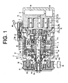
- a housing of a hybrid compressor includes a front housing 1, a center housing 2, a fixed scroll member 11 and a rear housing 3.
- the front housing 1 is fixed to the center housing 2.
- the hybrid compressor includes a compression mechanism 10, a drive mechanism 80, a speed-reducing mechanism 40 and an electromagnetic clutch 50.
- the compression mechanism 10 is located in the center housing 2, the fixed scroll member 11 and the rear housing 3.
- the drive mechanism 80 and the speed-reducing mechanism 40 are located in the front housing 1.
- the electromagnetic clutch 50 as a transmission mechanism is located outside the front housing 1.
- a first housing includes the center housing 2, the fixed scroll member 11 and the rear housing 3.
- the fixed scroll member 11 and the rear housing 3 correspond to a first housing main body, and the center housing 2 corresponds to a partition wall.
- the front housing 1 corresponds to a second housing.
- the compression mechanism 10 includes the fixed scroll member 11 and a movable scroll member 12 that are engaged with each other to define compression chambers 13.
- the fixed scroll member 11 includes a fixed base plate 11a, a shell portion 11b and a fixed spiral wall 11c.
- the shell portion 11b is fixed to the center housing 2 and the rear housing 3 and is sandwiched between the center housing 2 and the rear housing 3.
- the shell portion 11b constitutes the outer periphery of the fixed scroll member 11.
- the fixed base plate 11a has a disc shape and is formed integrally with the shell portion 11b at the side of the rear housing 3.
- the fixed spiral wall 11c protrudes from the fixed base plate 11a toward the center housing 2 in an involute curve.
- the movable scroll member 12 includes a movable base plate 12a, a movable spiral wall 12b and a boss 12c.
- the movable base plate 12a has a disc shape.
- the movable spiral wall 12b protrudes from the movable base plate 12a toward the rear housing 3 in an involute curve.
- the compression chambers 13 are defined by the fixed base plate 11a, the fixed spiral wall 11c, the movable base plate 12a and the movable spiral wall 12b.
- the boss 12c is formed on the movable base plate 12a in the center housing 2.
- a suction chamber 3b and a discharge chamber 3a are defined by the fixed scroll member 11 and the rear housing 3.
- a suction port extends through the outer periphery of the fixed base plate 11a to interconnect the suction chamber 3b and the compression chambers 13.
- the suction chamber 3b is also connected to an evaporator of a refrigeration circuit that is not shown.
- a discharge port 14 extends through the center of the fixed base plate 11a to interconnect the compression chambers 13 and the discharge chamber 3a.
- the discharge chamber 3a is connected to a condenser of the refrigeration circuit that is not shown.
- a shaft hole 2a is formed in the center housing 2.
- a rotary shaft 4 is inserted through the shaft hole 2a.
- a shaft seal device 21 is arranged between the rotary shaft 4 and the shaft hole 2a.
- the center housing 2 is hermetically fixed to the front housing 1.
- the rotary shaft 4 is rotatably supported by the center housing 2 via the shaft seal device 21 and a radial bearing 22.
- a slide key 23 is protruded from the inner end of a large diameter portion 4a of the rotary shaft 4 and is offset from a central axis S of the rotary shaft 4.
- a counter weight 24 is fitted to a drive bush 25 that is inserted to the slide key 23.
- the boss 12c of the movable scroll member 12 is supported by the drive bush 25 via a radial bearing 26.
- a self-rotation preventing mechanism 27 is provided between the center housing 2 and the movable base plate 12a for preventing the movable base plate 12a from self-rotating.
- the drive mechanism 80 includes a direct current motor (a DC motor) 81 for rotationally driving the rotary shaft 4 and a printed circuit board 87 that has integrated circuits (IC) for controlling the DC motor 81.
- the DC motor 81 includes a casing 82, a pair of permanent magnets 83, a rotor 84 and a brush 85.
- the casing 82 has a cylindrical shape.
- the outer circumferential surface of the casing 82 is fixed to the front housing 1.
- the pair of the permanent magnets 83 are fixed to the inner circumferential surface of the casing 82 and face each other.
- the rotor 84 has a cylindrical shape and is rotatably provided inside the casing 82.
- a plurality of salient poles has winding wire and is mounted on the outer circumferential surface of the rotor 84.
- the salient poles are arranged around the central axis S.
- the brush 85 electrically contacts the rotor 84 through a sun gear 42 for switching the direction of electric current applied to the winding wire.
- the brush 85 is electrically connected to the printed circuit board 87 via a connector 86.
- the printed circuit board 87 is connected via a cable 88 to a computer that is not shown.
- the speed-reducing mechanism 40 for reducing the rotational speed of the rotary shaft 4 relative to the rotational speed of the drive mechanism 80 transmits driving power from the drive mechanism 80 to the compression mechanism 10.
- the speed-reducing mechanism 40 includes a planetary gear mechanism that has the sun gear 42, three planetary gears 43 and an internal gear 44.
- a part 42a of the sun gear 42 is fitted into the rotor 84 of the DC motor 81 to rotate integrally.
- External gear teeth are formed on the outer circumferential surface of a part 42b of the sun gear 42.
- a shield bearing 41 is arranged between the sun gear 42 and the center housing 2.
- the sun gear 42 and the rotor 84 are rotatably supported by the center housing 2 via the shield bearing 41.
- Internal gear teeth are formed on the inner circumferential surface of the internal gear 44.
- the internal gear 44 is fixed to the front housing 1 and rotatably supports the sun gear 42 via a shield bearing 48.
- the three planetary gears 43 are rotatably provided between the sun gear 42 and the internal gear 44.
- External gear teeth are formed on the outer circumferential surface of each of the planetary gears 43 and are engaged with the external gear teeth of the sun gear 42 as well as the internal gear teeth of the internal gear 44.
- Each of the planetary gears 43 is connected to an arm 43a.
- the arm 43a is rotatably supported by the front housing 1 via a shield bearing 49, and the rotary shaft 4 is supported by the front housing 1 via a shaft seal device 46 and a shield bearing 45.
- the speed-reducing mechanism 40 is sealed by the shaft seal devices 21 and 46, the shield bearings 41, 48, 49 and 45.
- a space A is substantially defined by the sun gear 42, the rotary shaft 4 and the center housing 2 and is sealed by the shield bearing 41 and the shaft seal device 21.
- a space B is substantially defined by the sun gear 42, the planetary gears 43 and the internal gear 44 and is sealed by the shield bearing 48.
- a space C is substantially defined by the planetary gears 43, the arm 43a, the rotary shaft 4 and the front housing 1 and is sealed by the shield bearings 49 and 45 and the shaft seal device 46.
- the spaces A, B and C communicate with each other and constitute the internal space of the speed-reducing mechanism 40.
- Lubricating oil L is stored inside the spaces A, B and C of the speed-reducing mechanism 40 and does not leak to the outside due to the above sealing mechanism.
- the shaft seal devices 21 and 46, the shield bearings 41, 48, 49 and 45 correspond to a sealing mechanism.
- a one-way clutch 47 is arranged between the arm 43a of the speed-reducing mechanism 40 and the rotary shaft 4.
- the one-way clutch 47 is the same type of the one-way clutch as disclosed in Japan Unexamined Patent Publication No. 2002-276775.
- the one-way clutch 47 transmits power from the speed-reducing mechanism 40 to the rotary shaft 4 and blocks power from the rotary shaft 4 to the speed-reducing mechanism 40.
- the electromagnetic clutch 50 is provided outside the front housing 1.
- the electromagnetic clutch 50 includes a hub 53, a pulley 51 and a coil 52.
- the hub 53 has an armature and is fixed to the outer end of the rotary shaft 4.
- the pulley 51 is rotatably provided at the front housing 1 via a bearing device 54.
- the pulley 51 is wound to a belt that is not shown, and the belt is connected to an engine 60 as an external drive source.
- the coil 52 is fixed to the front housing 1 in the pulley 51. When an electric current is applied to the coil 52, the armature of the hub 53 moves and is magnetically connected to the pulley 51, and the rotary shaft 4 is rotated synchronously with the pulley 51. Thus, driving power is transmitted from the engine 60 to the rotary shaft 4.
- the drive mechanism 80 drives the compression mechanism 10. Namely, when the electric current is not applied to the coil 52 of the electromagnetic clutch 50, the pulley 51 and the hub 53 is separated from each other. Thus, the pulley 51 idles, and the driving power is not transmitted from the engine 60 to the rotary shaft 4.
- the rotor 84 rotates. Since the part 42a of the sun gear 42 of the planetary gear mechanism is fitted into the rotor 84, the sun gear 42 rotates integrally with the rotor 84. In accordance with the rotation of the sun gear 42, the arm 43a is rotated via the planetary gears 43.
- the rotational speed of the arm 43a is reduced due to the gear ratio among the sun gear 42, the planetary gears 43 and the internal gear 44. Then, the rotary shaft 4 rotates via the one-way clutch 47 at the same rotational speed of the arm 43a. Therefore, the rotation of the rotor 84 is transmitted to the drive shaft 4 via the speed-reducing mechanism 40 that reduces the rotational speed of the rotor 84.
- the engine 60 drives the compression mechanism 10 via the electromagnetic clutch 50.
- the rotor 84 does not rotate, and the driving power is not transmitted from the drive mechanism 80 to the rotary shaft 4 via the speed-reducing mechanism 40.
- the electric current is applied to the coil 52 of the electromagnetic clutch 50, the pulley 51 is magnetically connected to the hub 53, and the driving power is transmitted from the engine 60 to the rotary shaft 4 via the electromagnetic clutch 50.
- the compression mechanism 10 is driven as described above. In this way, the engine 60 drives the compression mechanism 10 via the electromagnetic clutch 50. Furthermore, when the electric current is not applied to DC motor 81 and the electromagnetic clutch 50, the drive of the compression mechanism 10 is stopped.
- the speed-reducing mechanism 40 that transmits the power from the drive mechanism 80 to the compression mechanism 10 is sealed by the shaft seal devices 21 and 46, the shield bearings 41, 48, 49 and 45 from the drive mechanism 80 and the compression mechanism 10.
- the lubricating oil L is utilized only for the speed-reducing mechanism 40 and sufficiently lubricates the speed-reducing mechanism 40.
- the lubricating oil L in the speed-reducing mechanism 40 is substantially prevented from leaking to the outside of the speed-reducing mechanism 40 due to the above sealing.
- the compression mechanism 10, the drive mechanism 80 and the electromagnetic clutch 50 are protected from the lubricating oil L.
- the drive mechanism 80 and the electromagnetic clutch 50 perform a long life in comparison to the prior art components due to the block of the damage caused by the lubricating oil. For the above reason, even though the hybrid compressor in the first preferred embodiment is used for a long period, the efficiency of the hybrid compressor is hard to deteriorate.
- the shaft seal device 21 is arranged between the rotary shaft 4 and the shaft hole 2a so that the center housing 2 is hermetically fixed to the front housing 1.
- the drive mechanism 80 is separated from the compression mechanism 10, and the refrigerant gas and lubricating oil in the compression mechanism 10 is prevented from invading the drive mechanism 80. Therefore, the DC motor 81 is utilized as the motor of the drive mechanism 80.
- the speed-reducing mechanism 40 for reducing the speed of the rotary shaft 4 transmits the power from the drive mechanism 80 to the compression mechanism 10 in the hybrid compressor, the rotational torque of the DC motor 81 can be small.
- the DC motor 81 is miniaturized, and the hybrid compressor is miniaturized due to the miniaturized DC motor 81.
- the one-way clutch 47 is arranged between the speed-reducing mechanism 40 and the rotary shaft 4 in the hybrid compressor.
- the one-way clutch 47 transmits the driving power from the DC motor 81 to the rotary shaft 4 via the speed-reducing mechanism 40 and blocks the power that is applied to the compression mechanism 10 from the rotary shaft 4 to the speed-reducing mechanism 40.
- the speed-reducing mechanism 40 and the drive mechanism 80 are not load for the compression mechanism 10, the compression mechanism 10 is prevented from being locked.
- the compression mechanism 10 is located in the first housing including the center housing 2, the fixed scroll member 11 and the rear housing 3.
- the speed-reducing mechanism 40 and the drive mechanism 80 are located in the second housing or the front housing 1.
- the second housing is fixed to the first housing.
- the second housing is only modified and the first housing is shared as a common portion, the structure and the combination of the drive mechanism 80 and the speed-reducing mechanism 40 are modified variously.
- the speed-reducing mechanism 40 and the one-way clutch 47 are alternatively removed from the hybrid compressor, and the rotor 84 of the drive mechanism 80 is directly connected to the rotary shaft 4.
- the driving power is transmitted from the engine 60 to the rotary shaft 4 via the electromagnetic clutch 50.
- the rotor 84 of the drive mechanism 80 is rotated in the permanent magnets 83.
- the drive mechanism 80 generates electric power and function as a power generation mechanism.
- the compression mechanism 10 does not substantially introduce, compress and discharge the refrigerant gas while the compression mechanism 10 is driven, all of the torque of the rotary shaft 4 is substantially utilized for generating the electric power.
- a pulley can be utilized to connect the engine 60 to the rotary shaft 4 instead of the electromagnetic clutch 50.
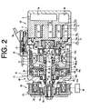
- a hosing of a hybrid compressor housing includes a front housing 1, a center housing 2, a fixed scroll member 11 and a rear housing 3.
- the front housing 1 is fixed to the center housing 2.
- the hybrid compressor also includes a compression mechanism 10, a drive mechanism 70, a speed-reducing mechanism 40 and an electromagnetic clutch 50.
- the compression mechanism 10 is located in the center housing 2, the fixed scroll member 11 and the rear housing 3.
- the drive mechanism 70 and the speed-reducing mechanism 40 are located in the front housing 1.
- the electromagnetic clutch 50 is located outside the front housing 1.
- a first housing includes the center housing 2, the fixed scroll member 11 and the rear housing 3.
- the fixed scroll member 11 and the rear housing 3 correspond to a first housing main body, and the center housing 2 corresponds to a partition wall.
- the front housing 1 corresponds to a second housing.
- the compression mechanism 10 includes the fixed scroll member 11 and a movable scroll member 12 that are engaged with each other to define compression chambers 13.
- the fixed scroll member 11 includes a fixed base plate 11a, a shell portion 11b and a fixed spiral wall 11c.
- the shell portion 11b is fixed to the center housing 2 and the rear housing 3 and is sandwiched between the center housing 2 and the rear housing 3.
- the shell portion 11b constitutes the outer periphery of the fixed scroll member 11.
- the fixed base plate 11a has a disc shape and is formed integrally with the shell portion 11 b at the side of the rear housing 3.
- the fixed spiral wall 11c protrudes from the fixed base plate 11a toward the center housing 2 in an involute curve.
- the movable scroll member 12 includes a movable base plate 12a, a movable spiral wall 12b and a boss 12c.
- the movable base plate 12a has a disc shape.
- the movable spiral wall 12b protrudes from the movable base plate 12a toward the rear housing 3 in an involute curve.
- the compression chambers 13 are defined by the fixed base plate 11a, the fixed spiral wall 11c, the movable base plate 12a and the movable spiral wall 12b.
- the boss 12c is formed on the movable base plate 12a in the center housing 2.
- a suction chamber 3b and a discharge chamber 3a are defined by the fixed scroll member 11 and the rear housing 3.
- a suction port extends through the outer periphery of the fixed base plate 11a to interconnect the suction chamber 3b and the compression chambers 13.
- the suction chamber 3b is connected to an evaporator of a refrigeration circuit that is not shown.
- a discharge port 14 extends through the center of the fixed base plate 11a and interconnects the compression chambers 13 and the discharge chamber 3a.
- the discharge chamber 3a is connected to a condenser of the refrigeration circuit that is not shown.
- a rotary shaft 4 is rotatably supported in the center housing 2 via a radial bearing 22.
- a slide key 23 is protruded from the inner end of a large diameter portion 4a of the rotary shaft 4 and is offset from a central axis S of the rotary shaft 4.
- a counter weight 24 is fitted to a drive bush 25 that is inserted to the slide key 23.
- the boss 12c of the movable scroll member 12 is supported by the drive bush 25 via a radial bearing 26.
- a self-rotation preventing mechanism 27 is provided between the center housing 2 and the movable base plate 12a for preventing the movable base plate 12a from self rotating.
- the drive mechanism 70 includes an induction motor 71 for rotationally driving the rotary shaft 4 and a printed circuit board 77 that has integrated circuits (IC) for controlling the induction motor 71.
- the induction motor 71 includes a yoke 72, a plurality of coils 73 and a rotor 74.
- the yoke 72 has a cylindrical shape, and the outer circumferential surface of the yoke 72 is fixed to the front housing 1.
- a plurality of the coils 73 is provided on the inner circumferential surface of the yoke 72.
- the rotor 74 has a cylindrical shape and is rotatably provided inside the yoke 72.
- the coils 73 are electrically connected to the printed circuit board 77 via a wiring and a connector 76.
- the wiring is partially shown in FIG. 2.
- the printed circuit board 77 is connected via a cable 78 to a computer that is not shown.
- the speed-reducing mechanism 40 is provided between the drive mechanism 70 and the compression mechanism 10.
- the speed-reducing mechanism 40 includes a planetary gear mechanism that has a sun gear 42, three planetary gears 43 and an internal gear 44.
- An O-ring 44a is provided on the outer circumferential surface of the internal gear 44.
- a part 42a of the sun gear 42 is fitted into the rotor 74 of the induction motor 71 to rotate integrally.
- External gear teeth are formed on the outer circumferential surface of a part 42b of the sun gear 42.
- the rotary shaft 4 is rotatably supported by the sun gear 42 via a shaft seal device 46c and a shield bearing 41.
- Internal gear teeth are formed on the inner circumferential surface of the internal gear 44.
- the internal gear 44 is fixed to the yoke 72 of the induction motor 71.
- the sun gear 42 is rotatably supported by the internal gear 44 via a shield bearing 48 and by the yoke 72 via a shaft seal device 46b.
- the three planetary gears 43 are rotatably provided between the sun gear 42 and the internal gear 44.
- External gear teeth are formed on the outer circumferential surface of each of the planetary gears 43 and are engaged with the external gear teeth of the sun gear 42 as well as the internal gear teeth of the internal gear 44.
- Each of the planetary gears 43 is connected to an arm 43a.
- the arm 43a is rotatably supported by the front housing 1 via a shield bearing 49, and the rotary shaft 4 is supported by the front housing 1 via a shaft seal device 46a and a shield bearing 45.
- the speed-reducing mechanism 40 is sealed by the shaft seal devices 46a, 46b and 46c, the shield bearings 41, 48, 49 and 45 and the O-ring 44a.
- a space A is substantially defined by the sun gear 42 and the rotary shaft 4 and is sealed by the shield bearing 41 and the shaft seal device 46c.
- a space B is substantially defined by the sun gear 42, the planetary gears 43 and the internal gear 44 and is sealed by the shield bearing 48 and the shaft seal device 46b.
- a space C is substantially defined by the planetary gears 43, the arm 43a, the rotary shaft 4 and the front housing 1 and is sealed by the shield bearings 49, 45 and the shaft seal device 46a.
- the spaces A, B and C communicate with each other and constitute the internal space of the speed-reducing mechanism 40.
- Lubricating oil L is stored inside the space A, B and C of the speed-reducing mechanism 40 and does not leak to the outside due to the above sealing mechanism.
- the shaft seal devices 46a, 46b and 46c, the shield bearings 41, 48, 49 and 45 and the O-ring 44a correspond to a sealing mechanism.
- a one-way clutch 47 is arranged between the arm 43a of the speed-reducing mechanism 40 and the rotary shaft 4.
- the one-way clutch 47 is the same type of the one-way clutch as disclosed in Japan Unexamined Patent Publication No. 2002-276775.
- the one-way clutch 47 transmits power from the speed-reducing mechanism 40 to the rotary shaft 4 and blocks power from the rotary shaft 4 to the speed-reducing mechanism 40.
- the electromagnetic clutch 50 is provided outside the front housing 1.
- the electromagnetic clutch 50 includes a hub 53, a pulley 51 and a coil 52.
- the hub 53 has an armature and is fixed to the outer end of the rotary shaft 4.
- the pulley 51 is rotatably provided at the front housing 1 via a bearing device 54.
- the pulley 51 is wound to a belt that is not shown, and the belt is connected to an engine 60 as an external drive source.
- the coil 52 is fixed to the front housing 1 in the pulley 51. When electric current is applied to the coil 52, the armature of the hub 53 moves and is magnetically connected to the pulley 51, and the rotary shaft 4 is rotated synchronously with the pulley 51.
- driving power is transmitted from the engine 60 to the rotary shaft 4.
- the drive mechanism 70 when electric current is not applied to the electromagnetic clutch 51 but is applied to the induction motor 71, the drive mechanism 70 similarly drives the compression mechanism 10 as described in the first preferred embodiment.
- the electric current when the electric current is not applied to the induction motor 71 but is applied to the coil 52 of the electromagnetic clutch 50, the engine 60 drives the compression mechanism 10 via the electromagnetic clutch 50. Furthermore, when the electric current is not applied to the induction motor 71 and the electromagnetic clutch 50, the drive of the compression mechanism 10 is stopped.
- the speed-reducing mechanism 40 that the speed-reducing mechanism 40 that transmits the power from the drive mechanism 70 to the compression mechanism 10 is sealed by the shaft seal devices 46a, 46b and 46c, the shield bearings 41, 48, 49 and 45 and the O-ring 44a from the drive mechanism 70 and the compression mechanism 10.
- the lubricating oil L is utilized only for the speed-reducing mechanism 40 and sufficiently lubricates the speed-reducing mechanism 40.
- the lubricating oil L in the speed-reducing mechanism 40 is prevented from leaking to the outside of the speed-reducing mechanism 40.
- the compression mechanism 10, the drive mechanism 70 and the electromagnetic clutch 50 are protected from the lubricating oil L.
- the drive mechanism 70 and the electromagnetic clutch 50 are performed a long life in comparison to the prior art components due to the block of the damage caused by the lubricating oil. For the above reason, even though the hybrid compressor in the second preferred embodiment is used for a long period, the efficiency of the hybrid compressor is hard to deteriorate.
- the drive mechanism 70 communicates with the compression mechanism 10.
- the induction motor 71 is cooled and lubricated by the refrigerant gas and lubricating oil that are sent from the compression mechanism 10.
- the speed-reducing mechanism 40 for reducing the speed of the rotary shaft 4 transmits the power from the drive mechanism 70 to the compression mechanism 10 in the hybrid compressor, the rotational torque of the induction motor 71 can be small.
- the induction motor 71 is miniaturized, and the hybrid compressor is miniaturized due to the miniaturized induction motor 71.
- the one-way clutch 47 is arranged between the speed-reducing mechanism 40 and the rotary shaft 4 in the hybrid compressor.
- the one-way clutch 47 transmits the driving power from the induction motor 71 to the rotary shaft 4 via the speed-reducing mechanism 40 and blocks the driving power that is applied to the compression mechanism 10 from the rotary shaft 4 to the speed-reducing mechanism 40.
- the speed-reducing mechanism 40 and the drive mechanism 70 are not load for the compression mechanism 10, the compression mechanism 10 is prevented from being locked.
- the compression mechanism 10 is a scroll type.
- a vane type and a swash plate type are utilized as the compression mechanism.
- a hybrid compressor includes a housing, a rotary shaft, a compression mechanism and a drive mechanism.
- the rotary shaft is rotatably supported by the housing.
- the compression mechanism is located in the housing and connected to the rotary shaft for compressing refrigerant gas.
- the drive mechanism is located in the housing for driving the compression mechanism.
- a speed-changing mechanism is located in the housing for transmitting power from the drive mechanism to the compression mechanism via the rotary shaft. The speed-changing mechanism varies the rotational speed of the drive mechanism.
- a sealing mechanism is located in the housing for sealing a space partially defined by the speed-changing mechanism.
Landscapes
- Engineering & Computer Science (AREA)
- Mechanical Engineering (AREA)
- General Engineering & Computer Science (AREA)
- Applications Or Details Of Rotary Compressors (AREA)
- Rotary Pumps (AREA)
- Compressor (AREA)
- Compressors, Vaccum Pumps And Other Relevant Systems (AREA)
- Retarders (AREA)
Abstract
A hybrid compressor includes a housing, a rotary shaft, a compression mechanism and a drive mechanism. The rotary shaft is rotatably supported by the housing. The compression mechanism is located in the housing and connected to the rotary shaft for compressing refrigerant gas. The drive mechanism is located in the housing for driving the compression mechanism. A speed-changing mechanism is located in the housing for transmitting power from the drive mechanism to the compression mechanism via the rotary shaft. The speed-changing mechanism varies the rotational speed of the drive mechanism. A sealing mechanism is located in the housing for sealing a space partially defined by the speed-changing mechanism. <IMAGE>
Description
The present invention relates to a hybrid compressor preferably used in a
vehicle air-conditioning system.
Japanese Unexamined Patent Publication No. 11-93876 discloses a
hybrid compressor that includes a housing, a compression mechanism, a drive
mechanism and a transmission mechanism. The compression mechanism and
the drive mechanism are provided in the housing, and the transmission
mechanism is provided outside the housing. The compression mechanism sucks
refrigerant gas, compresses it and discharges it. The drive mechanism includes
an electric motor that rotates a rotary shaft through a speed-changing mechanism
for driving the compression mechanism. The transmission mechanism transmits
power to the drive shaft from an external drive source such as an engine that is
located outside the housing. This reference discloses scroll type and vane type
compression mechanisms, an induction motor as the electric motor of the drive
mechanism and an electromagnetic clutch as the transmission mechanism.
In the hybrid compressor, when the external drive source is in an
operational state, the power is transmitted from the external drive source to the
rotary shaft through the transmission mechanism to drive the compression
mechanism. On the other hand, when the external drive source is in a stop state,
the drive mechanism rotates the rotary shaft through the speed-changing
mechanism that reduces the rotational speed of the rotary shaft to drive the
compression mechanism. Thus, even if the external drive source is either in the
operational state or the stop state, the compressor is operated to work the vehicle
air-conditioning system. Therefore, comfort of car interior is maintained.
Meanwhile, the refrigerant gas and the lubricating oil sent from the
compression mechanism respectively cool and lubricate the electric motor and
the speed-changing mechanism. However, it has been proven in prior art that the
lubricating oil sent only from the compression mechanism is insufficient for
lubricating the speed-changing mechanism. Thus, in the conventional hybrid
compressor, the function of the speed-changing mechanism deteriorates after a
long period of time, and the efficiency and the life of the hybrid compressor also
deteriorate.
The present invention provides a hybrid compressor that maintains its
efficiency and its life even though the hybrid compressor is used for a long period
of time.
According to the present invention, a hybrid compressor includes a
housing, a rotary shaft, a compression mechanism and a drive mechanism. The
rotary shaft is rotatably supported by the housing. The compression mechanism
is located in the housing and connected to the rotary shaft for compressing
refrigerant gas. The drive mechanism is located in the housing for driving the
compression mechanism. A speed-changing mechanism is located in the housing
for transmitting power from the drive mechanism to the compression mechanism
via the rotary shaft. The speed-changing mechanism varies the rotational speed
of the drive mechanism. A sealing mechanism is located in the housing for
sealing a space partially defined by the speed-changing mechanism.
The features of the present invention that are believed to be novel are set
forth with particularity in the appended claims. The invention together with objects
and advantages thereof, may best be understood by reference to the following
description of the presently preferred embodiments together with the
accompanying drawings in which:
First and second preferred embodiments according to the present
invention will be respectively described in reference to FIGs. 1 and 2. Now, the
first preferred embodiment will be described. As show in FIG. 1, a housing of a
hybrid compressor includes a front housing 1, a center housing 2, a fixed scroll
member 11 and a rear housing 3. The front housing 1 is fixed to the center
housing 2. The hybrid compressor includes a compression mechanism 10, a
drive mechanism 80, a speed-reducing mechanism 40 and an electromagnetic
clutch 50. The compression mechanism 10 is located in the center housing 2, the
fixed scroll member 11 and the rear housing 3. The drive mechanism 80 and the
speed-reducing mechanism 40 are located in the front housing 1. The
electromagnetic clutch 50 as a transmission mechanism is located outside the
front housing 1. A first housing includes the center housing 2, the fixed scroll
member 11 and the rear housing 3. The fixed scroll member 11 and the rear
housing 3 correspond to a first housing main body, and the center housing 2
corresponds to a partition wall. The front housing 1 corresponds to a second
housing.
The compression mechanism 10 includes the fixed scroll member 11 and
a movable scroll member 12 that are engaged with each other to define
compression chambers 13. The fixed scroll member 11 includes a fixed base
plate 11a, a shell portion 11b and a fixed spiral wall 11c. The shell portion 11b is
fixed to the center housing 2 and the rear housing 3 and is sandwiched between
the center housing 2 and the rear housing 3. The shell portion 11b constitutes the
outer periphery of the fixed scroll member 11. The fixed base plate 11a has a disc
shape and is formed integrally with the shell portion 11b at the side of the rear
housing 3. The fixed spiral wall 11c protrudes from the fixed base plate 11a
toward the center housing 2 in an involute curve. The movable scroll member 12
includes a movable base plate 12a, a movable spiral wall 12b and a boss 12c.
The movable base plate 12a has a disc shape. The movable spiral wall 12b
protrudes from the movable base plate 12a toward the rear housing 3 in an
involute curve. The compression chambers 13 are defined by the fixed base plate
11a, the fixed spiral wall 11c, the movable base plate 12a and the movable spiral
wall 12b. The boss 12c is formed on the movable base plate 12a in the center
housing 2.
A suction chamber 3b and a discharge chamber 3a are defined by the
fixed scroll member 11 and the rear housing 3. Although not shown, a suction port
extends through the outer periphery of the fixed base plate 11a to interconnect
the suction chamber 3b and the compression chambers 13. The suction chamber
3b is also connected to an evaporator of a refrigeration circuit that is not shown. A
discharge port 14 extends through the center of the fixed base plate 11a to
interconnect the compression chambers 13 and the discharge chamber 3a. The
discharge chamber 3a is connected to a condenser of the refrigeration circuit that
is not shown.
A shaft hole 2a is formed in the center housing 2. A rotary shaft 4 is
inserted through the shaft hole 2a. A shaft seal device 21 is arranged between the
rotary shaft 4 and the shaft hole 2a. Thus, the center housing 2 is hermetically
fixed to the front housing 1. The rotary shaft 4 is rotatably supported by the center
housing 2 via the shaft seal device 21 and a radial bearing 22. A slide key 23 is
protruded from the inner end of a large diameter portion 4a of the rotary shaft 4
and is offset from a central axis S of the rotary shaft 4. A counter weight 24 is
fitted to a drive bush 25 that is inserted to the slide key 23. The boss 12c of the
movable scroll member 12 is supported by the drive bush 25 via a radial bearing
26. A self-rotation preventing mechanism 27 is provided between the center
housing 2 and the movable base plate 12a for preventing the movable base plate
12a from self-rotating.
The drive mechanism 80 includes a direct current motor (a DC motor) 81
for rotationally driving the rotary shaft 4 and a printed circuit board 87 that has
integrated circuits (IC) for controlling the DC motor 81. The DC motor 81 includes
a casing 82, a pair of permanent magnets 83, a rotor 84 and a brush 85. The
casing 82 has a cylindrical shape. The outer circumferential surface of the casing
82 is fixed to the front housing 1. The pair of the permanent magnets 83 are fixed
to the inner circumferential surface of the casing 82 and face each other. The
rotor 84 has a cylindrical shape and is rotatably provided inside the casing 82. A
plurality of salient poles has winding wire and is mounted on the outer
circumferential surface of the rotor 84. The salient poles are arranged around the
central axis S. The brush 85 electrically contacts the rotor 84 through a sun gear
42 for switching the direction of electric current applied to the winding wire. The
brush 85 is electrically connected to the printed circuit board 87 via a connector
86. The printed circuit board 87 is connected via a cable 88 to a computer that is
not shown.
The speed-reducing mechanism 40 for reducing the rotational speed of
the rotary shaft 4 relative to the rotational speed of the drive mechanism 80
transmits driving power from the drive mechanism 80 to the compression
mechanism 10. The speed-reducing mechanism 40 includes a planetary gear
mechanism that has the sun gear 42, three planetary gears 43 and an internal
gear 44. A part 42a of the sun gear 42 is fitted into the rotor 84 of the DC motor 81
to rotate integrally. External gear teeth are formed on the outer circumferential
surface of a part 42b of the sun gear 42. A shield bearing 41 is arranged between
the sun gear 42 and the center housing 2. Thus, the sun gear 42 and the rotor 84
are rotatably supported by the center housing 2 via the shield bearing 41. Internal
gear teeth are formed on the inner circumferential surface of the internal gear 44.
The internal gear 44 is fixed to the front housing 1 and rotatably supports the sun
gear 42 via a shield bearing 48. The three planetary gears 43 are rotatably
provided between the sun gear 42 and the internal gear 44. External gear teeth
are formed on the outer circumferential surface of each of the planetary gears 43
and are engaged with the external gear teeth of the sun gear 42 as well as the
internal gear teeth of the internal gear 44. Each of the planetary gears 43 is
connected to an arm 43a. The arm 43a is rotatably supported by the front housing
1 via a shield bearing 49, and the rotary shaft 4 is supported by the front housing
1 via a shaft seal device 46 and a shield bearing 45. Thus, the speed-reducing
mechanism 40 is sealed by the shaft seal devices 21 and 46, the shield bearings
41, 48, 49 and 45. Namely, a space A is substantially defined by the sun gear 42,
the rotary shaft 4 and the center housing 2 and is sealed by the shield bearing 41
and the shaft seal device 21. A space B is substantially defined by the sun gear
42, the planetary gears 43 and the internal gear 44 and is sealed by the shield
bearing 48. A space C is substantially defined by the planetary gears 43, the arm
43a, the rotary shaft 4 and the front housing 1 and is sealed by the shield
bearings 49 and 45 and the shaft seal device 46. The spaces A, B and C
communicate with each other and constitute the internal space of the
speed-reducing mechanism 40. Lubricating oil L is stored inside the spaces A, B
and C of the speed-reducing mechanism 40 and does not leak to the outside due
to the above sealing mechanism. The shaft seal devices 21 and 46, the shield
bearings 41, 48, 49 and 45 correspond to a sealing mechanism.
A one-way clutch 47 is arranged between the arm 43a of the
speed-reducing mechanism 40 and the rotary shaft 4. The one-way clutch 47 is
the same type of the one-way clutch as disclosed in Japan Unexamined Patent
Publication No. 2002-276775. The one-way clutch 47 transmits power from the
speed-reducing mechanism 40 to the rotary shaft 4 and blocks power from the
rotary shaft 4 to the speed-reducing mechanism 40.
The electromagnetic clutch 50 is provided outside the front housing 1.
The electromagnetic clutch 50 includes a hub 53, a pulley 51 and a coil 52. The
hub 53 has an armature and is fixed to the outer end of the rotary shaft 4. The
pulley 51 is rotatably provided at the front housing 1 via a bearing device 54. The
pulley 51 is wound to a belt that is not shown, and the belt is connected to an
engine 60 as an external drive source. The coil 52 is fixed to the front housing 1 in
the pulley 51. When an electric current is applied to the coil 52, the armature of
the hub 53 moves and is magnetically connected to the pulley 51, and the rotary
shaft 4 is rotated synchronously with the pulley 51. Thus, driving power is
transmitted from the engine 60 to the rotary shaft 4. On the other hand, when
electric current is not applied to the coil 52, the armature of the hub 53 moves
away from the pulley 51, and the rotary shaft 4 is not rotated by the pulley 51.
Thus, the driving power is not transmitted from the engine 60 to the rotary shaft 4.
In the above-constructed hybrid compressor, when electric current is not
applied to the electromagnetic clutch 50 but is applied to the DC motor 81, the
drive mechanism 80 drives the compression mechanism 10. Namely, when the
electric current is not applied to the coil 52 of the electromagnetic clutch 50, the
pulley 51 and the hub 53 is separated from each other. Thus, the pulley 51 idles,
and the driving power is not transmitted from the engine 60 to the rotary shaft 4.
When the electric current is applied to the DC motor 81, the rotor 84 rotates.
Since the part 42a of the sun gear 42 of the planetary gear mechanism is fitted
into the rotor 84, the sun gear 42 rotates integrally with the rotor 84. In
accordance with the rotation of the sun gear 42, the arm 43a is rotated via the
planetary gears 43. The rotational speed of the arm 43a is reduced due to the
gear ratio among the sun gear 42, the planetary gears 43 and the internal gear 44.
Then, the rotary shaft 4 rotates via the one-way clutch 47 at the same rotational
speed of the arm 43a. Therefore, the rotation of the rotor 84 is transmitted to the
drive shaft 4 via the speed-reducing mechanism 40 that reduces the rotational
speed of the rotor 84.
When the rotary shaft 4 rotates, the slide key 23 orbits around the central
axis S. The cooperation of the drive bush 25 that is fitted to the slide key 23 and
the self-rotation preventing mechanism 27 allows the movable scroll member 12
to orbit around the central axis S. As the compression chamber 13 that is defined
by the fixed base plate 11a, the fixed spiral wall 11c, the movable base plate 12a
and the movable spiral wall 12b moves toward the center of the fixed scroll
member 11, the compression chambers 13 sequentially reduce in volume. In this
way, the compression mechanism 10 is driven by the rotation of the rotary shaft 4.
Refrigerant gas is introduced from the refrigeration circuit via the suction chamber
3b to the compression chambers 13 in a suction process and is compressed due
to the movement of the compression chambers 13. Then, the compressed
refrigerant gas is discharged from the compression chambers 13 to the
refrigeration circuit via the discharge port 14 and the discharge chamber 3a.
On the other hand, when electric current is not applied to the DC motor
81 but is applied to the coil 52 of the electromagnetic clutch 50, the engine 60
drives the compression mechanism 10 via the electromagnetic clutch 50. Namely,
when the electric current is not applied to the DC motor 81, the rotor 84 does not
rotate, and the driving power is not transmitted from the drive mechanism 80 to
the rotary shaft 4 via the speed-reducing mechanism 40. When the electric
current is applied to the coil 52 of the electromagnetic clutch 50, the pulley 51 is
magnetically connected to the hub 53, and the driving power is transmitted from
the engine 60 to the rotary shaft 4 via the electromagnetic clutch 50. When the
rotary shaft 4 rotates, the compression mechanism 10 is driven as described
above. In this way, the engine 60 drives the compression mechanism 10 via the
electromagnetic clutch 50. Furthermore, when the electric current is not applied to
DC motor 81 and the electromagnetic clutch 50, the drive of the compression
mechanism 10 is stopped.
In the hybrid compressor, the speed-reducing mechanism 40 that
transmits the power from the drive mechanism 80 to the compression mechanism
10 is sealed by the shaft seal devices 21 and 46, the shield bearings 41, 48, 49
and 45 from the drive mechanism 80 and the compression mechanism 10. Thus,
the lubricating oil L is utilized only for the speed-reducing mechanism 40 and
sufficiently lubricates the speed-reducing mechanism 40. Furthermore, the
lubricating oil L in the speed-reducing mechanism 40 is substantially prevented
from leaking to the outside of the speed-reducing mechanism 40 due to the above
sealing. Thus, the compression mechanism 10, the drive mechanism 80 and the
electromagnetic clutch 50 are protected from the lubricating oil L. The drive
mechanism 80 and the electromagnetic clutch 50 perform a long life in
comparison to the prior art components due to the block of the damage caused
by the lubricating oil. For the above reason, even though the hybrid compressor in
the first preferred embodiment is used for a long period, the efficiency of the
hybrid compressor is hard to deteriorate.
In the hybrid compressor, the shaft seal device 21 is arranged between
the rotary shaft 4 and the shaft hole 2a so that the center housing 2 is
hermetically fixed to the front housing 1. Thus, the drive mechanism 80 is
separated from the compression mechanism 10, and the refrigerant gas and
lubricating oil in the compression mechanism 10 is prevented from invading the
drive mechanism 80. Therefore, the DC motor 81 is utilized as the motor of the
drive mechanism 80.
Furthermore, since the speed-reducing mechanism 40 for reducing the
speed of the rotary shaft 4 transmits the power from the drive mechanism 80 to
the compression mechanism 10 in the hybrid compressor, the rotational torque of
the DC motor 81 can be small. Thus, the DC motor 81 is miniaturized, and the
hybrid compressor is miniaturized due to the miniaturized DC motor 81.
The one-way clutch 47 is arranged between the speed-reducing
mechanism 40 and the rotary shaft 4 in the hybrid compressor. The one-way
clutch 47 transmits the driving power from the DC motor 81 to the rotary shaft 4
via the speed-reducing mechanism 40 and blocks the power that is applied to the
compression mechanism 10 from the rotary shaft 4 to the speed-reducing
mechanism 40. Thus, since the speed-reducing mechanism 40 and the drive
mechanism 80 are not load for the compression mechanism 10, the compression
mechanism 10 is prevented from being locked.
The compression mechanism 10 is located in the first housing including
the center housing 2, the fixed scroll member 11 and the rear housing 3. The
speed-reducing mechanism 40 and the drive mechanism 80 are located in the
second housing or the front housing 1. The second housing is fixed to the first
housing. Thus, the second housing is only modified and the first housing is
shared as a common portion, the structure and the combination of the drive
mechanism 80 and the speed-reducing mechanism 40 are modified variously.
Meanwhile, the speed-reducing mechanism 40 and the one-way clutch
47 are alternatively removed from the hybrid compressor, and the rotor 84 of the
drive mechanism 80 is directly connected to the rotary shaft 4. When electric
current is applied to the electromagnetic clutch 50, the driving power is
transmitted from the engine 60 to the rotary shaft 4 via the electromagnetic clutch
50. As the rotary shaft 4 rotates, the rotor 84 of the drive mechanism 80 is rotated
in the permanent magnets 83. Thus, the drive mechanism 80 generates electric
power and function as a power generation mechanism. In this case, when the
compression mechanism 10 does not substantially introduce, compress and
discharge the refrigerant gas while the compression mechanism 10 is driven, all
of the torque of the rotary shaft 4 is substantially utilized for generating the electric
power. Furthermore, in this case, a pulley can be utilized to connect the engine 60
to the rotary shaft 4 instead of the electromagnetic clutch 50.
Now, the second preferred embodiment will be described. As shown in
FIG. 2, a hosing of a hybrid compressor housing includes a front housing 1, a
center housing 2, a fixed scroll member 11 and a rear housing 3. The front
housing 1 is fixed to the center housing 2. The hybrid compressor also includes a
compression mechanism 10, a drive mechanism 70, a speed-reducing
mechanism 40 and an electromagnetic clutch 50. The compression mechanism
10 is located in the center housing 2, the fixed scroll member 11 and the rear
housing 3. The drive mechanism 70 and the speed-reducing mechanism 40 are
located in the front housing 1. The electromagnetic clutch 50 is located outside
the front housing 1. A first housing includes the center housing 2, the fixed scroll
member 11 and the rear housing 3. The fixed scroll member 11 and the rear
housing 3 correspond to a first housing main body, and the center housing 2
corresponds to a partition wall. The front housing 1 corresponds to a second
housing.
The compression mechanism 10 includes the fixed scroll member 11 and
a movable scroll member 12 that are engaged with each other to define
compression chambers 13. The fixed scroll member 11 includes a fixed base
plate 11a, a shell portion 11b and a fixed spiral wall 11c. The shell portion 11b is
fixed to the center housing 2 and the rear housing 3 and is sandwiched between
the center housing 2 and the rear housing 3. The shell portion 11b constitutes the
outer periphery of the fixed scroll member 11. The fixed base plate 11a has a disc
shape and is formed integrally with the shell portion 11 b at the side of the rear
housing 3. The fixed spiral wall 11c protrudes from the fixed base plate 11a
toward the center housing 2 in an involute curve. The movable scroll member 12
includes a movable base plate 12a, a movable spiral wall 12b and a boss 12c.
The movable base plate 12a has a disc shape. The movable spiral wall 12b
protrudes from the movable base plate 12a toward the rear housing 3 in an
involute curve. The compression chambers 13 are defined by the fixed base plate
11a, the fixed spiral wall 11c, the movable base plate 12a and the movable spiral
wall 12b. The boss 12c is formed on the movable base plate 12a in the center
housing 2.
A suction chamber 3b and a discharge chamber 3a are defined by the
fixed scroll member 11 and the rear housing 3. Although not shown, a suction port
extends through the outer periphery of the fixed base plate 11a to interconnect
the suction chamber 3b and the compression chambers 13. The suction chamber
3b is connected to an evaporator of a refrigeration circuit that is not shown. A
discharge port 14 extends through the center of the fixed base plate 11a and
interconnects the compression chambers 13 and the discharge chamber 3a. The
discharge chamber 3a is connected to a condenser of the refrigeration circuit that
is not shown.
A rotary shaft 4 is rotatably supported in the center housing 2 via a radial
bearing 22. A slide key 23 is protruded from the inner end of a large diameter
portion 4a of the rotary shaft 4 and is offset from a central axis S of the rotary
shaft 4. A counter weight 24 is fitted to a drive bush 25 that is inserted to the slide
key 23. The boss 12c of the movable scroll member 12 is supported by the drive
bush 25 via a radial bearing 26. A self-rotation preventing mechanism 27 is
provided between the center housing 2 and the movable base plate 12a for
preventing the movable base plate 12a from self rotating.
The drive mechanism 70 includes an induction motor 71 for rotationally
driving the rotary shaft 4 and a printed circuit board 77 that has integrated circuits
(IC) for controlling the induction motor 71. The induction motor 71 includes a yoke
72, a plurality of coils 73 and a rotor 74. The yoke 72 has a cylindrical shape, and
the outer circumferential surface of the yoke 72 is fixed to the front housing 1. A
plurality of the coils 73 is provided on the inner circumferential surface of the yoke
72. The rotor 74 has a cylindrical shape and is rotatably provided inside the yoke
72. The coils 73 are electrically connected to the printed circuit board 77 via a
wiring and a connector 76. The wiring is partially shown in FIG. 2. The printed
circuit board 77 is connected via a cable 78 to a computer that is not shown.
The speed-reducing mechanism 40 is provided between the drive
mechanism 70 and the compression mechanism 10. The speed-reducing
mechanism 40 includes a planetary gear mechanism that has a sun gear 42,
three planetary gears 43 and an internal gear 44. An O-ring 44a is provided on
the outer circumferential surface of the internal gear 44. A part 42a of the sun
gear 42 is fitted into the rotor 74 of the induction motor 71 to rotate integrally.
External gear teeth are formed on the outer circumferential surface of a part 42b
of the sun gear 42. The rotary shaft 4 is rotatably supported by the sun gear 42
via a shaft seal device 46c and a shield bearing 41. Internal gear teeth are formed
on the inner circumferential surface of the internal gear 44. The internal gear 44 is
fixed to the yoke 72 of the induction motor 71. The sun gear 42 is rotatably
supported by the internal gear 44 via a shield bearing 48 and by the yoke 72 via a
shaft seal device 46b. The three planetary gears 43 are rotatably provided
between the sun gear 42 and the internal gear 44. External gear teeth are formed
on the outer circumferential surface of each of the planetary gears 43 and are
engaged with the external gear teeth of the sun gear 42 as well as the internal
gear teeth of the internal gear 44. Each of the planetary gears 43 is connected to
an arm 43a. The arm 43a is rotatably supported by the front housing 1 via a shield
bearing 49, and the rotary shaft 4 is supported by the front housing 1 via a shaft
seal device 46a and a shield bearing 45. Thus, the speed-reducing mechanism
40 is sealed by the shaft seal devices 46a, 46b and 46c, the shield bearings 41,
48, 49 and 45 and the O-ring 44a. Namely, a space A is substantially defined by
the sun gear 42 and the rotary shaft 4 and is sealed by the shield bearing 41 and
the shaft seal device 46c. A space B is substantially defined by the sun gear 42,
the planetary gears 43 and the internal gear 44 and is sealed by the shield
bearing 48 and the shaft seal device 46b. A space C is substantially defined by
the planetary gears 43, the arm 43a, the rotary shaft 4 and the front housing 1
and is sealed by the shield bearings 49, 45 and the shaft seal device 46a. The
spaces A, B and C communicate with each other and constitute the internal space
of the speed-reducing mechanism 40. Lubricating oil L is stored inside the space
A, B and C of the speed-reducing mechanism 40 and does not leak to the outside
due to the above sealing mechanism. The shaft seal devices 46a, 46b and 46c,
the shield bearings 41, 48, 49 and 45 and the O-ring 44a correspond to a sealing
mechanism.
A one-way clutch 47 is arranged between the arm 43a of the
speed-reducing mechanism 40 and the rotary shaft 4. The one-way clutch 47 is
the same type of the one-way clutch as disclosed in Japan Unexamined Patent
Publication No. 2002-276775. The one-way clutch 47 transmits power from the
speed-reducing mechanism 40 to the rotary shaft 4 and blocks power from the
rotary shaft 4 to the speed-reducing mechanism 40.
The electromagnetic clutch 50 is provided outside the front housing 1.
The electromagnetic clutch 50 includes a hub 53, a pulley 51 and a coil 52. The
hub 53 has an armature and is fixed to the outer end of the rotary shaft 4. The
pulley 51 is rotatably provided at the front housing 1 via a bearing device 54. The
pulley 51 is wound to a belt that is not shown, and the belt is connected to an
engine 60 as an external drive source. The coil 52 is fixed to the front housing 1 in
the pulley 51. When electric current is applied to the coil 52, the armature of the
hub 53 moves and is magnetically connected to the pulley 51, and the rotary shaft
4 is rotated synchronously with the pulley 51. Thus, driving power is transmitted
from the engine 60 to the rotary shaft 4. On the other hand, when the electric
current is not applied to the coil 52, the armature of the hub 53 moves away from
the pulley 51, and the rotary shaft 4 is not rotated by the pulley 51. Thus, the
driving power is not transmitted from the engine 60 to the rotary shaft 4.
In the above-constructed hybrid compressor, when electric current is not
applied to the electromagnetic clutch 51 but is applied to the induction motor 71,
the drive mechanism 70 similarly drives the compression mechanism 10 as
described in the first preferred embodiment. On the other hand, when the electric
current is not applied to the induction motor 71 but is applied to the coil 52 of the
electromagnetic clutch 50, the engine 60 drives the compression mechanism 10
via the electromagnetic clutch 50. Furthermore, when the electric current is not
applied to the induction motor 71 and the electromagnetic clutch 50, the drive of
the compression mechanism 10 is stopped.
In the hybrid compressor, the speed-reducing mechanism 40 that the
speed-reducing mechanism 40 that transmits the power from the drive
mechanism 70 to the compression mechanism 10 is sealed by the shaft seal
devices 46a, 46b and 46c, the shield bearings 41, 48, 49 and 45 and the O-ring
44a from the drive mechanism 70 and the compression mechanism 10. Thus, the
lubricating oil L is utilized only for the speed-reducing mechanism 40 and
sufficiently lubricates the speed-reducing mechanism 40. Furthermore, the
lubricating oil L in the speed-reducing mechanism 40 is prevented from leaking to
the outside of the speed-reducing mechanism 40. Thus, the compression
mechanism 10, the drive mechanism 70 and the electromagnetic clutch 50 are
protected from the lubricating oil L. The drive mechanism 70 and the
electromagnetic clutch 50 are performed a long life in comparison to the prior art
components due to the block of the damage caused by the lubricating oil. For the
above reason, even though the hybrid compressor in the second preferred
embodiment is used for a long period, the efficiency of the hybrid compressor is
hard to deteriorate.
In the hybrid compressor, the drive mechanism 70 communicates with
the compression mechanism 10. Thus, the induction motor 71 is cooled and
lubricated by the refrigerant gas and lubricating oil that are sent from the
compression mechanism 10.
Furthermore, since the speed-reducing mechanism 40 for reducing the
speed of the rotary shaft 4 transmits the power from the drive mechanism 70 to
the compression mechanism 10 in the hybrid compressor, the rotational torque of
the induction motor 71 can be small. Thus, the induction motor 71 is miniaturized,
and the hybrid compressor is miniaturized due to the miniaturized induction motor
71.
The one-way clutch 47 is arranged between the speed-reducing
mechanism 40 and the rotary shaft 4 in the hybrid compressor. The one-way
clutch 47 transmits the driving power from the induction motor 71 to the rotary
shaft 4 via the speed-reducing mechanism 40 and blocks the driving power that is
applied to the compression mechanism 10 from the rotary shaft 4 to the
speed-reducing mechanism 40. Thus, since the speed-reducing mechanism 40
and the drive mechanism 70 are not load for the compression mechanism 10, the
compression mechanism 10 is prevented from being locked.
In the above-described first and second preferred embodiments, the
compression mechanism 10 is a scroll type. However, a vane type and a swash
plate type are utilized as the compression mechanism.
The present examples and embodiments are to be considered as
illustrative and not restrictive, and the invention is not to be limited to the details
given herein but may be modified within the scope of the appended claims.
A hybrid compressor includes a housing, a rotary shaft, a compression
mechanism and a drive mechanism. The rotary shaft is rotatably supported by the
housing. The compression mechanism is located in the housing and connected to
the rotary shaft for compressing refrigerant gas. The drive mechanism is located
in the housing for driving the compression mechanism. A speed-changing
mechanism is located in the housing for transmitting power from the drive
mechanism to the compression mechanism via the rotary shaft. The
speed-changing mechanism varies the rotational speed of the drive mechanism.
A sealing mechanism is located in the housing for sealing a space partially
defined by the speed-changing mechanism.
Claims (16)
- A hybrid compressor including a housing (1, 2, 3, 11), a rotary shaft (4), a compression mechanism (10) and a drive mechanism (70, 80), the rotary shaft (4) being rotatably supported by the housing (1, 2, 3, 11), the compression mechanism (10) being located in the housing (1, 2, 3, 11) and connected to the rotary shaft (4) for compressing refrigerant gas, the drive mechanism (70, 80) being located in the housing (1, 2, 3, 11) for driving the compression mechanism (10), characterized in that a speed-changing mechanism (40) is located in the housing (1, 2, 3, 11) for transmitting power from the drive mechanism (70, 80) to the compression mechanism (10) via the rotary shaft (4), the speed-changing mechanism (40) varying the rotational speed of the drive mechanism (70, 80) to a different rotational speed of the rotary shaft (4), and in that a sealing mechanism (21, 46, 46a, 46b, 46c, 41, 45, 48, 49, 44a) is located in the housing (1, 2, 3, 11) for sealing a space (A, B, C) partially defined by the speed-changing mechanism (40).
- The hybrid compressor according to claim 1, wherein the housing (1, 2, 3, 11) includes a first housing (2, 3, 11) and a second housing (1) that are fixed to each other, the compression mechanism (10) being located in the first housing (2, 3, 11), the drive mechanism (70, 80) and the speed-changing mechanism (40) being located in the second housing (1).
- The hybrid compressor according to claim 2, wherein the first housing (2, 3, 11) includes a first housing main body (3, 11) and a center housing (2) having a shaft hole (2a) through which the rotary shaft (4) is inserted, the second housing (1) being hermetically fixed to the first housing (2, 3, 11), the sealing mechanism (21) being located between the rotary shaft (4) and the shaft hole (2a).
- The hybrid compressor according to any one of claims 1 through 3, further including a transmission mechanism (50) provided outside the housing (1, 2, 3, 11) which transmits power from an external drive source (60) to the rotary shaft (4) for driving the compression mechanism (10).
- The hybrid compressor according to any one of claims 1 through 4, wherein the speed-changing mechanism (40) reduces the rotational speed of the rotary shaft (4) relative to the rotational speed of the drive mechanism (70, 80).
- The hybrid compressor according to any one of claims 1 through 5, wherein the speed-changing mechanism (40) and the housing (1, 2) together define a space (A, B, C) for storing lubricant (L) that lubricates the speed-changing mechanism (40), the space (A, B, C) being sealed by the sealing mechanism (21, 46, 46a, 46b, 46c, 41, 45, 48, 49, 44a).
- The hybrid compressor according to any one of claims 1 through 6, wherein the sealing mechanism (41, 49, 44a) is located between the housing (1, 2) and the speed-changing mechanism (40).
- The hybrid compressor according to any one of claims 6 and 7, wherein the rotary shaft (4) extends through the space (A, B, C), the sealing mechanism (21, 45, 46, 46a) being located between the housing (1, 2) and the rotary shaft (4).
- The hybrid compressor according to any one of claims 6 through 8, wherein the rotary shaft (4) extends through the space, the sealing mechanism (41, 46c) being located between the speed-changing mechanism (40) and the rotary shaft (4).
- The hybrid compressor according to any one of claims 1 through 9, wherein the speed-changing mechanism (40) includes a first gear (42) and a second gear (44).
- The hybrid compressor according to claim 10, wherein the sealing mechanism (48) is located between the first gear (42) and the drive mechanism (70).
- The hybrid compressor according to claim 6, wherein the speed-changing mechanism (40) includes a first gear (42); the rotary shaft (4) extending through the space (A, B, C), the space (A, B, C) including a first space (A) substantially defined by the first gear (42), the rotary shaft (4) and the housing (2); and the sealing mechanism (41, 21) sealing the first space (A).
- The hybrid compressor according to claim 6, wherein the speed-changing mechanism (40) includes a first gear (42); the rotary shaft (4) extending through the space (A, B, C), the space (A, B, C) including a first space (A) substantially defined by the first gear (42) and the rotary shaft (4); and the sealing mechanism (41, 46c) sealing the first space (A).
- The hybrid compressor according to any one of claims 6, 12 and 13, wherein the speed-changing mechanism (40) includes a first gear (42), a second gear (44) and a third gear (43); the space (A, B, C) including a second space (B) substantially defined by the first gear (42), the second gear (44) and the third gear (43); and the sealing mechanism (46b, 48) sealing the second space (B).
- The hybrid compressor according to any one of claims 6 and 12 through 14, wherein the speed-changing mechanism (40) includes a third gear (43) and an arm (43a); the rotary shaft (4) extending through the space (A, B, C), the space (A, B, C) including a third space (C) substantially defined by the third gear (43), the arm (43a), the rotary shaft (4) and the housing (1); and the sealing mechanism (45, 46, 46a, 49) sealing the third space (C).
- The hybrid compressor according to claim 1, wherein the speed-changing mechanism (40) and a portion of the housing (1, 2) for housing the speed-changing mechanism (40) provide the space (A, B, C) to maintain lubricant (L), the portion of the housing (1, 2) and the speed-changing mechanism (40) being sealed by the sealing mechanism (21, 46, 46a, 46b, 46c, 41, 45, 48, 49, 44a) so as to contain the lubricant (L) in the space (A, B, C).
Applications Claiming Priority (2)
| Application Number | Priority Date | Filing Date | Title |
|---|---|---|---|
| JP2003096121 | 2003-03-31 | ||
| JP2003096121A JP2004301054A (en) | 2003-03-31 | 2003-03-31 | Hybrid compressor |
Publications (1)
| Publication Number | Publication Date |
|---|---|
| EP1464839A1 true EP1464839A1 (en) | 2004-10-06 |
Family
ID=32844640
Family Applications (1)
| Application Number | Title | Priority Date | Filing Date |
|---|---|---|---|
| EP04007456A Withdrawn EP1464839A1 (en) | 2003-03-31 | 2004-03-26 | Hybrid compressor |
Country Status (3)
| Country | Link |
|---|---|
| US (1) | US20040202550A1 (en) |
| EP (1) | EP1464839A1 (en) |
| JP (1) | JP2004301054A (en) |
Cited By (4)
| Publication number | Priority date | Publication date | Assignee | Title |
|---|---|---|---|---|
| CN102536813A (en) * | 2011-11-05 | 2012-07-04 | 佛山市广顺电器有限公司 | Automobile air conditioning scroll compressor |
| CN102734157A (en) * | 2011-03-30 | 2012-10-17 | 株式会社京浜 | Compressor |
| CN104329255A (en) * | 2013-07-22 | 2015-02-04 | 卡森尼可关精株式会社 | Gas compressor |
| EP2072754A3 (en) * | 2007-12-18 | 2015-05-06 | Kabushiki Kaisha Toyota Jidoshokki | Motor-driven compressor with multi-part casing |
Families Citing this family (14)
| Publication number | Priority date | Publication date | Assignee | Title |
|---|---|---|---|---|
| US6742350B2 (en) * | 2001-11-03 | 2004-06-01 | Nippon Soken, Inc. | Hybrid compressor device |
| JP4173345B2 (en) * | 2002-10-03 | 2008-10-29 | 本田技研工業株式会社 | Vehicle drive device |
| US7841845B2 (en) | 2005-05-16 | 2010-11-30 | Emerson Climate Technologies, Inc. | Open drive scroll machine |
| JP5491420B2 (en) * | 2009-01-30 | 2014-05-14 | パナソニック株式会社 | Scroll compressor |
| DE102010015151A1 (en) | 2010-04-16 | 2011-10-20 | Knorr-Bremse Systeme für Schienenfahrzeuge GmbH | Compressor flange for screw compressors |
| JP5482706B2 (en) * | 2011-03-28 | 2014-05-07 | 株式会社豊田自動織機 | Compressor with transmission |
| JP2014015901A (en) * | 2012-07-10 | 2014-01-30 | Toyota Industries Corp | Scroll type expander |
| CN102996454A (en) * | 2012-12-24 | 2013-03-27 | 乔建设 | Single-stage disk double-acting scroll compressor |
| CN103047141A (en) * | 2012-12-26 | 2013-04-17 | 皮德智 | Mechanical and electrical double-driven scroll compressor with single acting disc |
| JP7345131B2 (en) * | 2019-08-05 | 2023-09-15 | パナソニックIpマネジメント株式会社 | compressor |
| JP6812050B1 (en) * | 2019-08-08 | 2021-01-13 | コアレスモータ株式会社 | Coreless motors and generators |
| CN110469507A (en) * | 2019-09-19 | 2019-11-19 | 广东兴泽尔新能源科技有限公司 | Driving mechanism and screw compressor |
| CN111734629A (en) * | 2020-08-11 | 2020-10-02 | 山东永申机电科技有限公司 | The deceleration clutch mechanism and the motor transmission device of the air-conditioning compressor of the electrified dual-drive automobile |
| US12241467B2 (en) * | 2022-12-29 | 2025-03-04 | Mahle International Gmbh | Assembly and electric compressor with modular stator assembly |
Citations (5)
| Publication number | Priority date | Publication date | Assignee | Title |
|---|---|---|---|---|
| JPH0539777A (en) * | 1991-05-07 | 1993-02-19 | Nippondenso Co Ltd | Compressor provided with transmission |
| JPH1193876A (en) * | 1997-07-24 | 1999-04-06 | Denso Corp | Combined compression device |
| JPH11287182A (en) * | 1998-04-02 | 1999-10-19 | Calsonic Corp | Compressor for vehicle air conditioner |
| US6234769B1 (en) * | 1997-07-09 | 2001-05-22 | Denso Corporation | Hybrid type compressor driven by engine and electric motor |
| EP1221391A2 (en) * | 2001-01-09 | 2002-07-10 | Kabushiki Kaisha Toyota Jidoshokki | Air-conditioning system for vehicle and its control method |
-
2003
- 2003-03-31 JP JP2003096121A patent/JP2004301054A/en active Pending
-
2004
- 2004-03-22 US US10/805,711 patent/US20040202550A1/en not_active Abandoned
- 2004-03-26 EP EP04007456A patent/EP1464839A1/en not_active Withdrawn
Patent Citations (5)
| Publication number | Priority date | Publication date | Assignee | Title |
|---|---|---|---|---|
| JPH0539777A (en) * | 1991-05-07 | 1993-02-19 | Nippondenso Co Ltd | Compressor provided with transmission |
| US6234769B1 (en) * | 1997-07-09 | 2001-05-22 | Denso Corporation | Hybrid type compressor driven by engine and electric motor |
| JPH1193876A (en) * | 1997-07-24 | 1999-04-06 | Denso Corp | Combined compression device |
| JPH11287182A (en) * | 1998-04-02 | 1999-10-19 | Calsonic Corp | Compressor for vehicle air conditioner |
| EP1221391A2 (en) * | 2001-01-09 | 2002-07-10 | Kabushiki Kaisha Toyota Jidoshokki | Air-conditioning system for vehicle and its control method |
Non-Patent Citations (3)
| Title |
|---|
| PATENT ABSTRACTS OF JAPAN vol. 017, no. 330 (M - 1434) 23 June 1993 (1993-06-23) * |
| PATENT ABSTRACTS OF JAPAN vol. 1999, no. 09 30 July 1999 (1999-07-30) * |
| PATENT ABSTRACTS OF JAPAN vol. 2000, no. 01 31 January 2000 (2000-01-31) * |
Cited By (5)
| Publication number | Priority date | Publication date | Assignee | Title |
|---|---|---|---|---|
| EP2072754A3 (en) * | 2007-12-18 | 2015-05-06 | Kabushiki Kaisha Toyota Jidoshokki | Motor-driven compressor with multi-part casing |
| CN102734157A (en) * | 2011-03-30 | 2012-10-17 | 株式会社京浜 | Compressor |
| CN102536813A (en) * | 2011-11-05 | 2012-07-04 | 佛山市广顺电器有限公司 | Automobile air conditioning scroll compressor |
| CN102536813B (en) * | 2011-11-05 | 2015-11-25 | 佛山市广顺电器有限公司 | A kind of scroll compressor of automobile air conditioner |
| CN104329255A (en) * | 2013-07-22 | 2015-02-04 | 卡森尼可关精株式会社 | Gas compressor |
Also Published As
| Publication number | Publication date |
|---|---|
| US20040202550A1 (en) | 2004-10-14 |
| JP2004301054A (en) | 2004-10-28 |
Similar Documents
| Publication | Publication Date | Title |
|---|---|---|
| US20040202550A1 (en) | Hybrid compressor | |
| US6443712B2 (en) | Hybrid type compressor driven by engine and electric motor | |
| US7147443B2 (en) | Electric compressor | |
| US20090162222A1 (en) | Motor-driven compressor | |
| JP2004270614A (en) | Electric compressor | |
| US20040247458A1 (en) | Fluid machine | |
| JP2001304127A (en) | Motor-driven compressor | |
| JP2004301055A (en) | Hybrid compressor | |
| JP4225101B2 (en) | Electric compressor | |
| US20110200468A1 (en) | Power driven compressor system for vehicles | |
| JP2004270564A (en) | Hybrid compressor | |
| US20050124446A1 (en) | Positioning structure for power transmission mechanism | |
| KR20140079019A (en) | a variable hybrid compressor | |
| JP4747941B2 (en) | Electric compressor | |
| JP2003083245A (en) | Combined drive compressor | |
| KR20260040980A (en) | Balanced rolling piston compressor with central mass reductions for improved compressor stability | |
| JP2007138778A (en) | Scroll compressor | |
| JP2025130038A (en) | Electric compressor with passive pressure system between high pressure and low pressure zones | |
| JP2004144048A (en) | Hybrid compressor | |
| WO2024195356A1 (en) | Refrigerant circuit module | |
| WO2024190809A1 (en) | Electric compressor | |
| WO2024237017A1 (en) | Inverter-integrated electric compressor | |
| JP2004176560A (en) | Hybrid compressor | |
| JP3924853B2 (en) | Combined compression device | |
| JP2008014283A (en) | Scroll compressor |
Legal Events
| Date | Code | Title | Description |
|---|---|---|---|
| PUAI | Public reference made under article 153(3) epc to a published international application that has entered the european phase |
Free format text: ORIGINAL CODE: 0009012 |
|
| 17P | Request for examination filed |
Effective date: 20040330 |
|
| AK | Designated contracting states |
Kind code of ref document: A1 Designated state(s): AT BE BG CH CY CZ DE DK EE ES FI FR GB GR HU IE IT LI LU MC NL PL PT RO SE SI SK TR |
|
| AX | Request for extension of the european patent |
Extension state: AL LT LV MK |
|
| STAA | Information on the status of an ep patent application or granted ep patent |
Free format text: STATUS: THE APPLICATION HAS BEEN WITHDRAWN |
|
| 18W | Application withdrawn |
Effective date: 20050304 |