EP1464798A1 - Structure for fixing catalytic body to exhaust pipe - Google Patents
Structure for fixing catalytic body to exhaust pipe Download PDFInfo
- Publication number
- EP1464798A1 EP1464798A1 EP04005603A EP04005603A EP1464798A1 EP 1464798 A1 EP1464798 A1 EP 1464798A1 EP 04005603 A EP04005603 A EP 04005603A EP 04005603 A EP04005603 A EP 04005603A EP 1464798 A1 EP1464798 A1 EP 1464798A1
- Authority
- EP
- European Patent Office
- Prior art keywords
- exhaust pipe
- case
- catalytic body
- engine
- intake
- Prior art date
- Legal status (The legal status is an assumption and is not a legal conclusion. Google has not performed a legal analysis and makes no representation as to the accuracy of the status listed.)
- Granted
Links
Images










Classifications
-
- F—MECHANICAL ENGINEERING; LIGHTING; HEATING; WEAPONS; BLASTING
- F01—MACHINES OR ENGINES IN GENERAL; ENGINE PLANTS IN GENERAL; STEAM ENGINES
- F01N—GAS-FLOW SILENCERS OR EXHAUST APPARATUS FOR MACHINES OR ENGINES IN GENERAL; GAS-FLOW SILENCERS OR EXHAUST APPARATUS FOR INTERNAL-COMBUSTION ENGINES
- F01N13/00—Exhaust or silencing apparatus characterised by constructional features
- F01N13/18—Construction facilitating manufacture, assembly, or disassembly
- F01N13/1838—Construction facilitating manufacture, assembly, or disassembly characterised by the type of connection between parts of exhaust or silencing apparatus, e.g. between housing and tubes, between tubes and baffles
-
- F—MECHANICAL ENGINEERING; LIGHTING; HEATING; WEAPONS; BLASTING
- F01—MACHINES OR ENGINES IN GENERAL; ENGINE PLANTS IN GENERAL; STEAM ENGINES
- F01N—GAS-FLOW SILENCERS OR EXHAUST APPARATUS FOR MACHINES OR ENGINES IN GENERAL; GAS-FLOW SILENCERS OR EXHAUST APPARATUS FOR INTERNAL-COMBUSTION ENGINES
- F01N3/00—Exhaust or silencing apparatus having means for purifying, rendering innocuous, or otherwise treating exhaust
- F01N3/08—Exhaust or silencing apparatus having means for purifying, rendering innocuous, or otherwise treating exhaust for rendering innocuous
- F01N3/10—Exhaust or silencing apparatus having means for purifying, rendering innocuous, or otherwise treating exhaust for rendering innocuous by thermal or catalytic conversion of noxious components of exhaust
- F01N3/24—Exhaust or silencing apparatus having means for purifying, rendering innocuous, or otherwise treating exhaust for rendering innocuous by thermal or catalytic conversion of noxious components of exhaust characterised by constructional aspects of converting apparatus
- F01N3/28—Construction of catalytic reactors
- F01N3/2839—Arrangements for mounting catalyst support in housing, e.g. with means for compensating thermal expansion or vibration
- F01N3/2842—Arrangements for mounting catalyst support in housing, e.g. with means for compensating thermal expansion or vibration specially adapted for monolithic supports, e.g. of honeycomb type
-
- F—MECHANICAL ENGINEERING; LIGHTING; HEATING; WEAPONS; BLASTING
- F01—MACHINES OR ENGINES IN GENERAL; ENGINE PLANTS IN GENERAL; STEAM ENGINES
- F01N—GAS-FLOW SILENCERS OR EXHAUST APPARATUS FOR MACHINES OR ENGINES IN GENERAL; GAS-FLOW SILENCERS OR EXHAUST APPARATUS FOR INTERNAL-COMBUSTION ENGINES
- F01N13/00—Exhaust or silencing apparatus characterised by constructional features
- F01N13/18—Construction facilitating manufacture, assembly, or disassembly
-
- F—MECHANICAL ENGINEERING; LIGHTING; HEATING; WEAPONS; BLASTING
- F01—MACHINES OR ENGINES IN GENERAL; ENGINE PLANTS IN GENERAL; STEAM ENGINES
- F01N—GAS-FLOW SILENCERS OR EXHAUST APPARATUS FOR MACHINES OR ENGINES IN GENERAL; GAS-FLOW SILENCERS OR EXHAUST APPARATUS FOR INTERNAL-COMBUSTION ENGINES
- F01N2350/00—Arrangements for fitting catalyst support or particle filter element in the housing
- F01N2350/02—Fitting ceramic monoliths in a metallic housing
- F01N2350/04—Fitting ceramic monoliths in a metallic housing with means compensating thermal expansion
-
- F—MECHANICAL ENGINEERING; LIGHTING; HEATING; WEAPONS; BLASTING
- F01—MACHINES OR ENGINES IN GENERAL; ENGINE PLANTS IN GENERAL; STEAM ENGINES
- F01N—GAS-FLOW SILENCERS OR EXHAUST APPARATUS FOR MACHINES OR ENGINES IN GENERAL; GAS-FLOW SILENCERS OR EXHAUST APPARATUS FOR INTERNAL-COMBUSTION ENGINES
- F01N2450/00—Methods or apparatus for fitting, inserting or repairing different elements
- F01N2450/02—Fitting monolithic blocks into the housing
-
- F—MECHANICAL ENGINEERING; LIGHTING; HEATING; WEAPONS; BLASTING
- F01—MACHINES OR ENGINES IN GENERAL; ENGINE PLANTS IN GENERAL; STEAM ENGINES
- F01N—GAS-FLOW SILENCERS OR EXHAUST APPARATUS FOR MACHINES OR ENGINES IN GENERAL; GAS-FLOW SILENCERS OR EXHAUST APPARATUS FOR INTERNAL-COMBUSTION ENGINES
- F01N2450/00—Methods or apparatus for fitting, inserting or repairing different elements
- F01N2450/22—Methods or apparatus for fitting, inserting or repairing different elements by welding or brazing
-
- F—MECHANICAL ENGINEERING; LIGHTING; HEATING; WEAPONS; BLASTING
- F01—MACHINES OR ENGINES IN GENERAL; ENGINE PLANTS IN GENERAL; STEAM ENGINES
- F01N—GAS-FLOW SILENCERS OR EXHAUST APPARATUS FOR MACHINES OR ENGINES IN GENERAL; GAS-FLOW SILENCERS OR EXHAUST APPARATUS FOR INTERNAL-COMBUSTION ENGINES
- F01N2450/00—Methods or apparatus for fitting, inserting or repairing different elements
- F01N2450/24—Methods or apparatus for fitting, inserting or repairing different elements by bolts, screws, rivets or the like
-
- F—MECHANICAL ENGINEERING; LIGHTING; HEATING; WEAPONS; BLASTING
- F01—MACHINES OR ENGINES IN GENERAL; ENGINE PLANTS IN GENERAL; STEAM ENGINES
- F01N—GAS-FLOW SILENCERS OR EXHAUST APPARATUS FOR MACHINES OR ENGINES IN GENERAL; GAS-FLOW SILENCERS OR EXHAUST APPARATUS FOR INTERNAL-COMBUSTION ENGINES
- F01N3/00—Exhaust or silencing apparatus having means for purifying, rendering innocuous, or otherwise treating exhaust
- F01N3/08—Exhaust or silencing apparatus having means for purifying, rendering innocuous, or otherwise treating exhaust for rendering innocuous
- F01N3/10—Exhaust or silencing apparatus having means for purifying, rendering innocuous, or otherwise treating exhaust for rendering innocuous by thermal or catalytic conversion of noxious components of exhaust
- F01N3/24—Exhaust or silencing apparatus having means for purifying, rendering innocuous, or otherwise treating exhaust for rendering innocuous by thermal or catalytic conversion of noxious components of exhaust characterised by constructional aspects of converting apparatus
- F01N3/28—Construction of catalytic reactors
- F01N3/2839—Arrangements for mounting catalyst support in housing, e.g. with means for compensating thermal expansion or vibration
-
- F—MECHANICAL ENGINEERING; LIGHTING; HEATING; WEAPONS; BLASTING
- F01—MACHINES OR ENGINES IN GENERAL; ENGINE PLANTS IN GENERAL; STEAM ENGINES
- F01N—GAS-FLOW SILENCERS OR EXHAUST APPARATUS FOR MACHINES OR ENGINES IN GENERAL; GAS-FLOW SILENCERS OR EXHAUST APPARATUS FOR INTERNAL-COMBUSTION ENGINES
- F01N3/00—Exhaust or silencing apparatus having means for purifying, rendering innocuous, or otherwise treating exhaust
- F01N3/08—Exhaust or silencing apparatus having means for purifying, rendering innocuous, or otherwise treating exhaust for rendering innocuous
- F01N3/10—Exhaust or silencing apparatus having means for purifying, rendering innocuous, or otherwise treating exhaust for rendering innocuous by thermal or catalytic conversion of noxious components of exhaust
- F01N3/24—Exhaust or silencing apparatus having means for purifying, rendering innocuous, or otherwise treating exhaust for rendering innocuous by thermal or catalytic conversion of noxious components of exhaust characterised by constructional aspects of converting apparatus
- F01N3/28—Construction of catalytic reactors
- F01N3/2839—Arrangements for mounting catalyst support in housing, e.g. with means for compensating thermal expansion or vibration
- F01N3/2875—Arrangements for mounting catalyst support in housing, e.g. with means for compensating thermal expansion or vibration by using elastic means, e.g. spring leaves, for retaining catalyst body in the housing
Definitions
- the present invention relates to an improvement in a catalytic body fixing structure for fixing a catalytic body to an exhaust pipe serving as part of an exhaust system joined to an engine, the catalytic body having a cylindrical case made of a material different from the exhaust pipe.
- the catalytic body can be fixed to the exhaust pipe by welding as is the case with the conventional structure.
- the case of the catalytic body and the exhaust pipe are made of different materials, it is difficult to provide the above welded fixing structure. Therefore, there has been a limitation on the freedom in choosing materials for the case of the catalytic body and the exhaust pipe.
- the present invention has been made under the above circumstances. It is an object of the present invention to provide a structure for fixing a catalytic body to an exhaust pipe.
- the structure is capable of housing a catalytic body in an exhaust pipe and fixing the catalytic body to the exhaust pipe even if a case of the catalytic body and the exhaust pipe are made of different materials, thus increasing the freedom in choosing materials for the case of the catalytic body and the exhaust pipe.
- a catalytic body fixing structure for fixing a catalytic body to an exhaust pipe serving as part of an exhaust system joined to an engine, the catalytic body having a cylindrical case made of a material different from the exhaust pipe and housed in the exhaust pipe.
- a bracket made of the same material as the exhaust pipe is welded to an inner circumferential surface of the exhaust pipe, the bracket being crimped on the case of the catalytic body.
- a catalytic body fixing structure for fixing a catalytic body to an exhaust pipe serving as part of an exhaust system joined to an engine, the catalytic body having a cylindrical case made of a material different from the exhaust pipe and housed in the exhaust pipe.
- a bracket made of the same material as the exhaust pipe is welded to an inner circumferential surface of the exhaust pipe, the bracket being coupled to the case of the catalytic body by a rivet.
- a catalytic body fixing structure for fixing a catalytic body to an exhaust pipe serving as part of an exhaust system joined to an engine, the catalytic body having a cylindrical case made of a material different from the exhaust pipe and housed in the exhaust pipe.
- a bracket made of the same material as the exhaust pipe is welded to an inner circumferential surface of the exhaust pipe, the bracket being fastened to the case of the catalytic body.
- the catalytic body has a cylindrical catalyst support for allowing an exhaust gas to flow therethrough, the cylindrical catalyst support being housed in the cylindrical case and having an end disposed inwardly of an end of the case, the bracket being crimped on the end of the case in a region projecting from the end of the catalyst support.
- the catalytic body has a cylindrical catalyst support for allowing an exhaust gas to flow therethrough, the cylindrical catalyst support being housed in the cylindrical case and having an end disposed inwardly of an end of the case, the bracket being coupled by the rivet to the end of the case in a region projecting from the end of the catalyst support.
- the catalytic body has a cylindrical catalyst support for allowing an exhaust gas to flow therethrough, the cylindrical catalyst support being housed in the cylindrical case and having an end disposed inwardly of an end of the case, the bracket being fastened to the end of the case in a region projecting from the end of the catalyst support.
- the catalytic body can be fixed to the exhaust pipe by a simple structure without affecting the catalyst support.
- FIGS. 1 through 19 show a first embodiment of the present invention.
- the motorcycle has a vehicle frame F including a head pipe 22 by which a front fork 21 rotably supporting a front wheel WF is steerably supported, a pair of left and right main frames 23 extending rearwardly and downwardly from the head pipe 22, a pair of left and right engine hangers 24 welded to the head pipe 22 and front portions of the main frames 23 and extending downwardly from the main frames 23, joint pipes 25 joining support plates 33 mounted on lower portions of the engine hangers 24 and rear portions of the main frames 23, a pair of left and right pivot plates 26 extending downwardly from the rear portions of the main frames 23, a first cross pipe 27 disposed between front portions of the main frames 23, a second cross pipe 28 disposed between upper portions of the pivot plates 26, a third cross pipe 29 disposed between lower portions of the pivot plates 26, and a pair of left and right seat rails 30 extending rearwardly and upwardly and joined to rear portions of the main frames 23.
- a vehicle frame F including a head pipe 22 by which a front fork 21 rotably supporting a front wheel WF
- the head pipe 22 has, integrally therewith, a cylindrical portion 22a by which the front fork 21 is steerably supported and a pair of left and right gussets 22b extending rearwardly and downwardly from the cylindrical portion 22a.
- the main frames 23 include the gussets 22b, pipes 31 having front ends welded to the gussets 22b, and pipes 26a integral with the pivot plates 26 and welded to rear ends of the pipes 31.
- attachment holes 32 are coaxially provided in inner side walls of the main frames 23, and the first cross pipe 27 has its opposite ends inserted in the respective attachment holes 32 and welded to the inner side walls of the main frames 23.
- the gussets 22b of the head pipe 22 have integral extensions 22c disposed inwardly of front inner side walls of the pipes 31 and extending rearwardly, the extensions 22c serving as front inner side walls of the main frames 23.
- the attachment holes 32 are provided in the respective extensions 22c, and the opposite ends of the first cross pipe 27 are inserted in the respective attachment holes 32 in confronting relation to the front inner side walls of the pipes 31.
- the opposite ends of the first cross pipe 27 are welded to outer surfaces of the extensions 22c.
- the pipes 31 are formed from an ingot of aluminum alloy into a transverse outer profile in the shape of a prismatic tube by a conventional known extrusion or drawing process.
- the pipes 31 have integral ribs 34 extending between vertically intermediate inner surfaces thereof and dividing the interior of the pipes 31 into upper and lower regions.
- the pipes 31 have lower portions to which the engine hangers 24 are welded and which are open downwardly, i.e., toward the engine hangers 24.
- the pipes 31 are in the shape of a vertically elongate prismatic shape having respective inner side walls 31a, which are flat substantially the full vertical length thereof, and respective outer side walls 31b extending substantially along the inner side walls 31a.
- the pipes 31 are bent in a plane PL perpendicular to the inner side walls 31a such that the pipes 31 have respective longitudinally intermediate portions, which are outwardly projected.
- the bent pipes 31 are inclined progressively toward each other in the upward direction and are joined to the respective gussets 22b of the head pipe 22.
- the front fork 21 includes cushion units 35 extending vertically on respective left and right sides of the front wheel WF, a bottom bridge 36 interconnecting the cushion units 35 above the front wheel WF, and a top bridge 37 interconnecting upper portions of the cushion units 35.
- the front wheel WF has an axle 38 supported between the lower ends of the cushion units 35.
- a steering shaft 39 which extends parallel to the cushion units 35, is disposed between the bottom bridge 36 and the top bridge 37 behind a central region between the cushion units 35.
- the steering shaft 39 is turnably supported by a tubular portion 22a of the head pipe 22.
- Left and right bar-shaped steering handles 40 are connected to the respective upper ends of the cushion units 35 above the bottom bridge 36.
- a steering damper 41 is disposed between the front end of the vehicle frame F, i.e., the head pipe 22, and the top bridge 37 of the front fork 21.
- the steering damper 41 includes a housing 42 incorporating a hydraulic damping mechanism (not shown) and fixedly supported on the head pipe 22, a turn shaft 43 disposed above the steering shaft 39 coaxially therewith and turnably supported on the housing 42, an arm 44 having a proximal end fixed to the turn shaft 43 and extending forwardly, a resilient roller 45 supported rotably on the distal end of the arm 44, and a recess 46 provided in an upper central surface of the top bridge 37 and held in fitting frictional contact with the outer circumferential surface of the resilient roller 45.
- Rotational vibrations about the steering shaft 39 which are transmitted from the front wheel WF to the top bridge 37, are attenuated by the hydraulic damping mechanism in the housing 42 through the arm 44.
- the engine E which is a multi-cylinder engine having four cylinders, for example, arrayed parallel transversely across the vehicle frame F, has an engine body 50 supported on lower portions of the engine hangers 24 and upper and lower portions of the pivot plates 26.
- the engine body 50 is fastened to the lower portions of the engine hangers 24 by a pair of left and right bolts 51.
- an insertion hole 53 for inserting a mount bolt 52 therethrough and a first engaging surface 54 surrounding the outer end of the insertion hole 53 are provided in a lower portion of one of the pivot plates 26 (in the present embodiment, the pivot plate 26 positioned on the right side when viewed forwardly in the direction of travel of the motorcycle).
- the insertion hole 53 which is open at an inner side surface of the pivot plate 26, and a first entry hole 55, which is larger in diameter than the insertion hole 53 and which is open at an outer side surface of the pivot plate 26, are provided in the lower portion of the pivot plate 26.
- the first engaging surface 54 is formed as an annular step facing the first entry hole 55 between the outer end of the insertion hole 53 and the inner end of the first entry hole 55.
- the engine body 50 has a pair of integral support arms 50a disposed between the pivot plates 26 and spaced from each other in the axial direction of the mount bolt 52.
- the support arms 50a have respective through holes 56 provided coaxially therein for the insertion of the mount bolt 52 therethrough.
- the lower portion of the other pivot plate 26 has a threaded hole 57 coaxial with the insertion hole 53 and a second engaging surface 58 surrounding the outer end of the threaded hole 57.
- the threaded hole 57 which is open at an inner side surface of the pivot plate 26, and a second entry hole 59 which is larger in diameter than the threaded hole 57 and which is open at an outer side surface of the pivot plate 26, are provided in the lower portion of the pivot plate 26.
- the second engaging surface 58 is formed as an annular step facing the second entry hole 59 between the outer end of the threaded hole 57 and the inner end of the second entry hole 59.
- a tubular bolt 60 is threaded in the threaded hole 57 and has an end held in abutment against the engine body 50. Specifically, while one of the support arms 50a is being held in abutment against an inner side surface of one of the pivot plates 26, the tubular bolt 60 is threaded in the threaded hole 57 with the end thereof held in abutment against the other support arm 50a.
- a tubular retaining bolt 61 is also threaded in the threaded hole 57 in abutment against the other end of the tubular bolt 60 to prevent the tubular bolt 60 from working loose.
- the tubular bolt 60 and the retaining bolt 61 are threaded in the threaded hole 57 with the other end of the tubular bolt 60 and the retaining bolt 61 being positioned inwardly of the second engaging surface 58 while the engine body 50 is being sandwiched between the inner side surface of the one of the pivot plates 26 and the end of the tubular bolt 60.
- the mount bolt 52 is inserted through the insertion hole 53, the through holes 56 in the engine body 50, the tubular bolt 60, the retaining bolt 61, and the threaded hole 57.
- the mount bolt 52 has a larger-diameter head 52a on an end thereof, which engages with one of the first and second engaging surfaces 54, 58, and a nut 63 engaging the other of the first and second engaging surfaces 54, 58 is threaded over the other end of the mount bolt 52.
- the other end of the mount bolt 52 whose larger-diameter head 52a engages with the first engaging surface 54 projects from the threaded hole 57, and the nut 63, which is threaded over the other end of the mount bolt 52 that projects from the threaded hole 57, engages with the second engaging surface 58 with a washer 62 interposed therebetween.
- a structure by which the engine body 50 is supported on the upper portions of the pivot plates 26 is basically the same as the structure by which the engine body 50 is supported on the lower portions of the pivot plates 26, and will not be described in detail below.
- a swing arm 66 has a front end swingably supported by a support shaft 67 on vertically intermediate portions of the pivot plates 26.
- a rear wheel WR has an axle 68 rotatably supported on the rear end of the swing arm 66.
- the engine body 50 incorporates therein a transmission whose output shaft 69 transmits power through a chain transmitting means 70 to the rear wheel WR.
- the chain transmitting means 70 includes a drive sprocket 71 fixed to the output shaft 69, a driven sprocket 72 fixed to the rear wheel WR, and an endless chain 73 trained around the sprockets 71, 72.
- the chain transmitting means 70 is disposed on the left side of the engine E when viewed forwardly in the direction of travel of the motorcycle.
- a link mechanism 74 is disposed between the third cross pipe 29 interconnecting the lower portions of the pivot plates 26 and the swing arm 66.
- the link mechanism 74 includes a first link 75 having an end joined to the third cross pipe 29 so as to be rotable about a first joint shaft 77 parallel to the support shaft 67, and a second link 76 joined to a lower portion of the swing arm 66 so as to be rotable about a second joint shaft 80 parallel to the first joint shaft 77 and joined to the other end of the first link 75 by a third joint shaft 81 parallel to the first and second joint shafts 77, 80.
- the third cross pipe 29 has a pair of integral shaft supports 29a projecting rearwardly from two locations that are longitudinally spaced from each other thereon.
- a collar 78 is mounted on the first joint shaft 77 that is disposed between the shaft supports 29a, and the first link 75 has an end supported on the collar 78 by a pair of roller bearings 79.
- a rear cushion unit 82 has an upper end coupled to a bracket 66a mounted on a front portion of the swing arm 66 and a lower end coupled to a front portion of the second link 76 by a fourth joint shaft 83.
- an air cleaner 87 for purifying air to be supplied to the engine E is disposed above a cylinder head 86 of the engine body 50 behind the head pipe 21 of the vehicle frame F.
- the air cleaner 87 has rear and upper portions covered with a fuel tank 88, which is mounted on the main frames 23 of the vehicle frame F.
- a radiator 89 is disposed forwardly of the engine body 50.
- a main seat 90 for the rider to ride on is supported on the seat rails 30 behind the fuel tank 88.
- a pillion seat 91 for a passenger to ride on is supported on the seat rails 30 at a position spaced rearwardly from the main seat 90.
- Straight intake passages 92 for guiding purified air from the air cleaner 87 above the cylinder head 86 are connected to an upper side wall of the cylinder head 86 in communication with the respective cylinders.
- the intake passages 92 include respective funnels 93 having upper open ends projecting into the air cleaner 87, and respective throttle bodies 94 connected to the respective lower ends of the funnels 93.
- the throttle bodies 94 are connected to the upper side wall of the cylinder head 86 with an insulator 95 interposed therebetween.
- the air cleaner 87 includes a cylindrical cleaner element 97 fixedly housed in a cleaner case 96, with a purification chamber 98 provided around the cleaner element 97 in the cleaner case 96 for being supplied with air that has been purified by passing through the cleaner element 97.
- the funnels 93 on the upper ends of the intake passages 92 are installed parallel to each other on the cleaner case 96 so as to be open into the purification chamber 98.
- First injectors 100 for injecting fuel when the engine E rotates at a high speed are mounted on the cleaner case 96 of the air cleaner 87 for the respective cylinders of the engine E.
- the first injectors 100 are disposed forwardly of central lines C1 of the intake passages 92, and are mounted on the cleaner case 96 so as to have their axes inclined to the central lines C1.
- a fuel pump (not shown) is disposed in the fuel tank 88 for supplying fuel to the first injectors 100.
- the fuel tank 88 has a fuel inlet port 101 provided in a front portion thereof.
- the first injectors 100 are disposed forwardly of a central line C2 of the fuel inlet port 101.
- the first injectors 100 are mounted on the cleaner case 96 such that their upper portions are disposed forwardly of points P of intersection between the central lines C1, C2 on a projection onto a plane parallel to the central line C2 of the fuel inlet port 101 and the central lines C1 of the intake passages 92.
- the throttle bodies 94 in the intake passages 92 house respective throttle valves (not shown) for controlling the amount of intake air flowing through the intake passages 92.
- a throttle drum 102 coupled to the throttle valves is disposed laterally of the throttle bodies 94.
- Second injectors 103 for ejecting fuel supplied from the fuel pump in the fuel tank 88 depending on the operating state of the engine E are disposed closer to the engine E than the throttle valves rearwardly and laterally of the throttle bodies 94.
- an intake duct 105 for introducing external air into the air cleaner 87 is disposed below the head pipe 21 at the front end of the vehicle frame F and extends forwardly from the air cleaner 87.
- the intake duct 105 has a rear end projecting into and fixed to a lower portion of the cleaner case 96 for introducing external air into the cleaner element 97 in the air cleaner 87.
- the intake duct 105 includes a rear main duct body 106 having a substantially triangular transverse cross-sectional shape including a transversely central portion raised upwardly and a lower open portion, a front main duct body 107 having substantially the same transverse cross-sectional shape as the rear main duct body 106 and joined to a front portion of the rear main duct body 106, and a lower lid plate 108 closing the lower open ends of the rear and front main duct bodies 106, 107.
- the intake duct 105 has a rear portion inclined upwardly in the rearward direction as viewed in side elevation.
- the lower lid plate 108 is fastened to the rear main duct body 106 by a plurality of screws 109 and also fastened to the front main duct body 107 by a plurality of screws 110.
- Support stays 111 are fixed by screws 112 to front lower surfaces of the pipes 31, which serve as part of the main frames 23 of the vehicle frame F.
- Attachment bosses 113 disposed on lower portions of opposite front sides of the intake duct 105 are fastened to the support stays 111 by screws 114, thus supporting the front portion of the intake duct 105 on the vehicle frame F.
- Positioning pins 113a inserted in the support stays 111 project on the attachment bosses 113.
- the radiator 89 is disposed below the intake duct 105.
- Stays 115 extend upwardly from opposite sides of the radiator 89.
- Welded nuts 116 are fixed to the support stays 111, and bolts 117 inserted through the stays 115 and the support stays 111 are threaded through the welded nuts 116, thus supporting the radiator 89 on the vehicle frame F.
- the lower lid plate 108 of the intake duct 105 has a pair of integral partition walls 118 held in abutment against lower surfaces of upper portions of the rear and front main duct bodies 106, 107.
- a first intake passage 119 whose transversely central portion is disposed on a transversely central line C3 of the front wheel WF and a pair of left and right second intake passages 120 disposed one on each side of the first intake passage 119, by the partition walls 118 between the first intake passage 119 and the second intake passages 120.
- the first intake passage 119 has a flow passage area greater than the total flow passage area of the second intake passages 120.
- the partition walls 118 have front portions inclined so as to be progressively spaced away from each other in the forward direction.
- the partition walls 118 have front ends held in abutment against inner surfaces of the opposite side walls of the front main duct body 107.
- the first intake passage 119 has a front portion, which is open forwardly at the front end of the intake duct 105, so as to occupy an entire end opening of the intake duct 105.
- the second intake passages 120 have respective front end openings 120a provided in the front end of the intake duct 105 so as to be open in a direction different from the direction in which the front end of the first intake passage 119 is open.
- the front end openings 120a are provided in the front main duct body 107 so as to be open upwardly on both left and right sides of the front end of the first intake passage 119.
- the front end of the intake duct 105 is of a substantially triangular shape as viewed from its front side.
- the front end of the intake duct 105 has an upper edge extending along the lower edge of a junction between the head pipe 21 and the main frames 23 and a lower edge extending along the upper portion of the radiator 89.
- a grill 121 is mounted on the front end of the intake duct 105.
- the grill 121 includes a frame member 122 complementary in shape to the front end opening edge of the intake duct 105 and a mesh member 123 having a peripheral edge supported on the frame member 122.
- Baffle plates 122a are integrally formed with the frame member 122 at respective positions spaced from the front end openings 120a of the second intake passages 120.
- the baffle plates 122a are fastened to front opposite sides of the front main duct body 107 of the intake duct 105 by screws 124.
- Positioning pins 125 for preventing a lower portion of the frame member 122 from being dislodged from the front end of the intake duct 105 project from the front end of the lower lid plate 108 and are inserted into the lower portion of the frame member 122.
- first intake passage 119 there is disposed a first butterfly intake control valve 126, which is controlled depending on the rotational speed of the engine E, for closing the first intake passage 119 when the engine E operates in a low rotational speed range and opening the first intake passage 119 when the engine E operates in a high rotational speed range.
- second intake passages 120 there are disposed second butterfly intake control valves 127, which are controlled depending on the rotational speed of the engine E, for opening the second intake passages 120 when the engine E operates in a low rotational speed range and closing the second intake passages 120 when the engine E operates in a high rotational speed range.
- the first butterfly intake control valve 126 and the second butterfly intake control valves 127 are fixed in common to a valve shaft 128.
- the shaft 128 has an axis perpendicular to the direction in which air flows through the first intake passage 119 and is turnably supported in the intake duct 105.
- the valve shaft 128 is rotatably supported on the partition walls 118 in regions of the intake duct 105, which correspond to the front end openings 120a of the second intake passages 120.
- screws 110 that fasten the front main duct body 107 to the lower lid plate 108, two pairs of screws 110 are threaded into the partition walls 118 at positions one on each side of the valve shaft 128.
- the first intake control valve 126 which changes the flow passage area of the first intake passage 119, is fixed to the valve shaft 128 such that it is inclined upwardly in the rearward direction when it closes the first intake passage 119, as shown in FIG. 14.
- the first intake control valve 126 has a portion above the valve shaft 128, which has an area greater than the area of a portion of the first intake control valve 126 beneath the valve shaft 128.
- the first intake control valve 126 opens the first intake passage 119, it lies substantially horizontally as indicated by the two-dot-and-dash lines in FIG. 14 to impose a minimum resistance on air flowing through the first intake passage 119.
- the second intake control valves 127 which change the flow passage areas of the second intake passages 120, are fixed to the valve shaft 128 such that they open the front end openings 120a of the second intake passages 120 when the first intake control valve 126 closes the first intake passage 119.
- a turn shaft 130 parallel to the valve shaft 128 is disposed rearwardly of the valve shaft 128 and below the intake duct 105.
- the turn shaft 130 is turnably supported by a plurality of bearings 129 projecting from a lower surface of the intake duct 105, i.e., a lower surface of the lower lid plate 108.
- An arm 130a is mounted on a portion of the turn shaft 130 corresponding to the first intake passage 119.
- a joint rod 131 which extends through the lower portion of the intake duct 105, i.e., the lower lid plate 108, has an end connected to a portion of the first intake control valve 126 as it is closed above the valve shaft 128 and an opposite end connected to the arm 130a.
- the first intake control valve 126 is turned between the closing side indicated by the solid lines in FIG. 14 and the opening side indicated by the two-dot-and-dash lines in FIG. 14.
- Return springs 132 for exerting spring forces to bias the turn shaft 130 and the valve shaft 128 in a direction to bring the first intake control valve 126 into the closing side are disposed between the opposite ends of the turn shaft 130 and the intake duct 105.
- the joint rod 131 movably extends through a through hole 133 provided in the lower lid plate 108.
- the through hole 133 is elongate in the fore-and-aft direction to allow the joint rod 131 extending through the lower lid plate 108 to move in the fore-and-aft direction as the arm 130a is turned in unison with the turn shaft 130.
- a driven pulley 134 is fixed to an end of the turn shaft 130. To the driven pulley 134, there is transmitted rotational power through a first transmission wire 135 from an actuator 141, which is supported on one of the support plates 33 in rear portions of the main frames 23 and disposed on the left side of an upper portion of the engine body 50.
- the actuator 141 includes a reversible electric motor and a speed-reduction mechanism for reducing the rotational speed of output power from the electric motor.
- the actuator 141 is mounted on a pair of brackets 33a of one of the support plates 33 of the vehicle frame F by a bolt 143 with resilient members 142 interposed therebetween.
- the actuator 141 has an output shaft 144 on which there is fixedly mounted a drive pulley 145 having a first small-diameter wire groove 146 and second and third large-diameter wire grooves 147, 148.
- the first transmission wire 135 for transmitting rotational power to the driven pulley 134 on the intake duct 105 has an end trained around and engaged with the first wire groove 146.
- An electronic control unit 149 is connected to the actuator 141, and controls operation of the actuator 141 depending on the rotational speed of the engine, which is input from a sensor (not shown).
- an exhaust system 150 connected to the engine E includes individual exhaust pipes 151 connected to a lower portion of a front side wall of the cylinder head 86 of the engine body 50, a pair of first joint exhaust pipes 152 to each of which a pair of individual exhaust pipes 151 is connected in common, a single second joint exhaust pipe 153 to which the first joint exhaust pipes 152 are connected in common, with a first exhaust muffler 154 disposed in an intermediate portion thereof, and a second exhaust muffler 155 connected to a downstream end of the second joint exhaust pipe 153.
- the individual exhaust pipes 151 extend downwardly from the front of the engine body 50, and the first joint exhaust pipes 152 extend substantially in the fore-and-aft direction below the engine body 50.
- the second joint exhaust pipe 153 is curved upwardly between the rear wheel WR and the engine body 50 and directed from below the engine body 50 to the right of the vehicle body, and then extends rearwardly above the rear wheel WR.
- the first exhaust muffler 154 is disposed in the rising portion of the second joint exhaust pipe 153, and a rear end outlet of the exhaust system 150, i.e., a downstream end of the second exhaust muffler 155, is disposed above the axle 68 of the rear wheel WR.
- the second joint exhaust pipe 153 which serves as part of the exhaust system 150, has a larger-diameter portion 153a positioned forwardly and upwardly of the axle 68 of the rear wheel WR.
- An exhaust control valve 156 is disposed in the larger-diameter portion 153a for changing the flow passage area in the second joint exhaust pipe 153 depending on the rotational speed of the engine E to control exhaust pulsations in the exhaust system 150.
- the exhaust control valve 156 When the engine E is in low and medium rotational speed ranges, the exhaust control valve 156 is operated into a closing side for increasing the output power of the engine E based on an exhaust pulsating effect in the exhaust system 150. When the engine E is in a high rotational speed range, the exhaust control valve 156 is operated into an opening side for increasing the output power of the engine E by reducing the resistance to the exhaust gas flow in the exhaust system 150.
- the exhaust control valve 156 is fixed to a valve shaft 157, which is turnably supported in the larger-diameter portion 153a of the second joint exhaust pipe 153.
- the valve shaft 157 has an end supported by a seal 159 in a bottomed cylindrical bearing housing 158 that is fixed to the larger-diameter portion 153a.
- the other end of the valve shaft 157 projects from the larger-diameter portion 153a with a seal 160 interposed between the other end of the valve shaft 157 and the larger-diameter portion 153a.
- a driven pulley 161 is fixed to the projecting end of the valve shaft 157.
- a return spring 162 for urging the valve shaft 157 in a direction to open the exhaust control valve 156 acts between the valve shaft 157 and the larger-diameter portion 153a.
- a case 165 which includes a cup-shaped main case body 163 fixed to the larger-diameter portion 153a and a lid plate 164 fastened to the main case body 163 in covering relation to an open end of the main case body 163.
- a limit arm 166 having a distal end projecting from the outer circumferential edge of the driven pulley 161 is fixed to the valve shaft 157 with the case 165.
- On an inner surface of the main case body 163 of the case 165 there are disposed a closing stopper 167 for engaging the distal end of the limit arm 166 to limit the end of turning to the closing side of the valve shaft 157, i.e., the discharge control valve 156, and an opening stopper 168 for engaging the distal end of the limit arm 166 to limit the end of turning to the opening side of the valve shaft 157, i.e., the discharge control valve 156.
- a second transmission wire 171 for operating the discharge control valve 156 into the closing side at the pulling time has an end trained around and engaged with the driven pulley 161.
- a third transmission wire 172 for operating the discharge control valve 156 into the opening side at the pulling time also has an end trained around and engaged with the driven pulley 161.
- the other end of the second transmission wire 171 is trained around and engaged with the second wire groove 147 of the drive pulley 145 of the actuator 141 in a direction opposite to the direction in which the first transmission wire 135 is trained.
- the other end of the third transmission wire 172 is trained around and engaged with the third wire groove 148 of the drive pulley 144 in the same direction as the direction in which the first transmission wire 135 is trained.
- the actuator 141 for actuating the exhaust control valve 156 that is controlled depending on the rotational speed of the engine E is coupled to the first intake control valve 126 for turning the first intake control valve 126 in the intake duct 105.
- the larger-diameter portion 153a where the exhaust control valve 156 is disposed should desirably be disposed below the main seat 90 for avoiding, as much as possible, unwanted external forces applied from above to the second and third transmission wires 171, 172.
- the case 165 is disposed so as to be exposed outwardly as viewed in side elevation in order to facilitate impingement thereon of the running airflow.
- the actuator 141 should desirably be disposed rearwardly and upwardly of the engine body 50 at such a position that the distance between the actuator 141 and the valve shaft 128 in the intake duct 105 and the distance between the actuator 141 and the valve shaft 157 of the exhaust valve 156 are substantially equal to each other. In this manner, any obstacles between the driven pulley 161 of the exhaust control valve 156 and the actuator 141 are minimized to allow the second and third transmission wires 171, 172, which interconnect the driven pulley 161 and the actuator 141, to be installed with ease.
- the first joint exhaust pipes 152 which serve as part of the exhaust system 150, have respective larger-diameter portions 152a positioned below the engine body 50.
- a catalytic body 175 is housed in each of the larger-diameter portions 152a. With the catalytic body 175 disposed below the engine body 50, the exhaust gas discharged from the cylinder head 86 can pass through the catalytic body 175 while the exhaust gas is kept at a relatively high temperature.
- the catalytic body 175 includes a cylindrical case 176 and a catalyst support 177, which is of a cylindrical shape for allowing the exhaust gas to pass therethrough, the catalyst support 177 being housed in the cylindrical case 176 and having an end disposed inwardly of an end of the case 176.
- the case 176 is made of a material different from the first joint exhaust pipe 152.
- the first joint exhaust pipe 152 is made of titanium
- the case 176 and the catalyst support 177 of the catalytic body 175 are made of stainless steel.
- a bracket 178 made of the same material, e.g., titanium, as the first joint exhaust pipe 152 is welded to an inner circumferential surface of the larger-diameter portions 152a of the first joint exhaust pipe 152.
- the bracket 178 includes a large ring 178a fitted in the larger-diameter portions 152a in surrounding relation to an end of the case 176, a small ring 178b contiguous to the large ring 178a with the end of the case 176 being fitted in the small ring 178b, and a plurality of, e.g., four, circumferentially equally spaced extension arms 178c extending from the small ring 178b in a direction opposite to the large ring 178a.
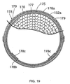
- the larger-diameter portions 152a has a plurality of circumferentially spaced through holes 179 provided therein so as to face the outer circumferential surface of the large ring 178a.
- the large ring 178a is welded to the larger-diameter portions 152a at the through holes 179, thus securing the bracket 178 to the larger-diameter portions 152a of the first joint exhaust pipe 152.
- the extension arms 178c are crimped on the end of the case 176 of the catalytic body 175.
- the bracket 178 welded to the larger-diameter portions 152a of the first joint exhaust pipe 152 is crimped on the end of the case 176, which projects from the end of the catalyst support 177.
- a ring 180 including a stainless mesh is spot-welded to the outer surface of the other end of the case 176 of the catalytic body 175.
- the ring 180 is interposed between the larger-diameter portions 152a of the first joint exhaust pipe 152 and the other end of the case 176, allowing the other end of the catalytic body 175 whose opposite end is fixed to the larger-diameter portions 152a by the bracket 178 to slide by way of thermal expansion. Therefore, stresses caused due to thermal expansion of the catalytic body 175 are prevented from being applied between the fixed end of the catalytic body 175 and the larger-diameter portions 152a.
- the front area of the head pipe 22 is covered with a front cowl 181 made of synthetic resin.
- Front opposite side areas of the vehicle body are covered, with a central cowl 182 made of synthetic resin which is contiguous to the front cowl 181.
- a lower cowl 183 made of synthetic resin, which covers opposite sides of the engine body 50, is contiguous to the central cowl 182.
- Rear portions of the seat rails 30 are covered with a rear cowl 184.
- An upper area of the front wheel WF is covered with a front fender 185 mounted on the front fork 21.
- a rear fender 186 covering an upper area of the rear wheel WR is mounted on the seat rails 30.
- the first cross pipe 27 is disposed between the front portions of the pair of left and right main frames 23 joined to the heat pipe 22 that is positioned at the front end of the vehicle frame F.
- the attachment holes 32 are coaxially provided in the inner side walls of the front portions of the main frames 23, and the first cross pipe 27 has its opposite ends inserted in the respective attachment holes 32 and welded to the inner side walls of the main frames 23.
- the head pipe 22 has the cylindrical portion 22a by which the front fork 21 is steerably supported and the pair of left and right gussets 22b extending rearwardly and downwardly from the cylindrical portion 22a.
- the main frames 23 include at least the gussets 22b and the pipes 31 welded respectively to the gussets 22b.
- the gussets 22b have the integral extensions 22c disposed inwardly of the front inner side walls of the pipes 31 and extending rearwardly, the extensions 22c serving as the front inner side walls of the main frames 23.
- the attachment holes 32 for inserting the opposite ends of the first cross pipe 27 therein in confronting relation to the front inner side walls of the pipes 31 are provided in the respective extensions 22c, and the opposite ends of the first cross pipe 27 are welded to the outer surfaces of the extensions 22c. Since the opposite ends of the first cross pipe 27 are welded to the outer surfaces of the extensions 22c, which are integral with the gussets 22b that serve as part of the main frames 23, the first cross pipe 27 can easily be welded to the main frame 23, and the appearance of the welded structure is fine as the welded regions are concealed from external view.
- the pipes 31 are in the shape of the vertically elongate prismatic shape having the respective inner side walls 31a, which are flat substantially the full vertical length thereof, and the respective outer side walls 31b extending substantially along the inner side walls 31a.
- the pipes 31 can be bent with ease because they are bent in the plane PL perpendicular to the inner side walls 31a.
- the pipes 31 are inclined progressively toward each other in the upward direction and are joined to the respective gussets 22b of the head pipe 22. Accordingly, with a simple structure of the inclined pipes 31, the space between the lower portions of the pipes 31 is widened to provide a sufficient installation space for the engine E, and the space between the upper portions of the pipes 31 is reduced to make the knees of the rider less liable to contact the pipes 31.
- the insertion hole 53 for inserting the mount bolt 52 therethrough and the first engaging surface 54 surrounding the outer end of the insertion hole 53 for engaging the larger-diameter head 52a on one end of the bolt 52 are provided in one of the pivot plates 26, and the other pivot plate 26 has the threaded hole 57 coaxial with the insertion hole 53 and the second engaging surface 58 surrounding the outer end of the threaded hole 57.
- the tubular bolt 60 is threaded in the threaded hole 57 with the other end of the tubular bolt 60 being positioned inwardly of the second engaging surface 58 while the engine body 50 is being sandwiched between the end of the tubular bolt 60 and the inner side surface of the one of the pivot plates 26.
- the nut 63 capable of engaging the engaging surface 58 is threaded over the other end of the mount bolt 52, which is inserted in the insertion hole 53, the engine body 50, the tubular bolt 60, and the threaded hole 57 and projects from the threaded hole 57.
- the opposite ends of the mount bolt 52 can be fastened to the vehicle frame F so as to be firmly axially positioned, thus increasing the rigidity with which the engine body 50 is supported.
- the tubular retaining bolt 61 which is held in abutment against the other end of the tubular bolt 60, is threaded in the threaded hole 57 so as to be positioned inwardly of the second engaging surface 58. Consequently, the retaining bolt 61 is held in contact with the other end of the tubular bolt 60 for effectively preventing the tubular bolt 60 from working loose.
- the straight intake passages 92 for guiding purified air from the air cleaner 87 disposed above the cylinder head 86 are connected to the upper side wall of the cylinder head 86 of the engine body 50.
- the first injectors 100 for injecting fuel into the intake passages 92 from above are mounted on the cleaner case 96 of the air cleaner 87, and the fuel tank 88 is disposed in covering relation to rear and upper areas of the air cleaner 87.
- the first injectors 100 are disposed forwardly of the central lines C1 of the intake passages 92.
- the first injectors 100 are disposed at a position offset forwardly from the central lines C1 of the intake passages 92.
- the bottom wall of the fuel tank 88 can be placed in a relatively low position while avoiding interference with the first injectors 100. Therefore, it is possible for the fuel tank 88 to have a sufficient capacity.
- the first injectors 100 are disposed forwardly of the central line C2 of the fuel inlet port 101 that is provided in the front portion of the fuel tank 88. As the first injectors 100 do not interfere with the fuel tank 88 on the central line C2 of the fuel inlet port 101, the fuel inlet port 101 can be placed in a lower position.
- the first injectors 100 are mounted on the cleaner case 96 of the air cleaner 87 such that their upper portions are disposed forwardly of the points P of intersection between the central lines C1, C2 on the projection onto the plane parallel to the central line C2 of the fuel inlet port 101 and the central lines C1 of the intake passages 92.
- the bottom wall of the fuel tank 88 can be placed in a relatively low position forwardly of the central line C2 of the fuel inlet port 101, making it possible for the fuel tank 88 and the air cleaner 87 to have a sufficient capacity, and also for a fuel supply nozzle to be inserted easily into the fuel inlet port 101 when the fuel is to be supplied to the fuel tank 88.
- the second injectors 103 for ejecting the fuel into the intake passages 92 are disposed rearwardly and laterally of the throttle bodies 94 in the intake passages 92.
- the first injectors 100 which are supplied with the fuel at a relatively low temperature and eject the fuel from above the intake passages 92 to contribute to an increase in the output power of the engine E, and the second injectors 103, which are capable of injecting the fuel in reaction with good response to the operation of the engine E, can be placed using the installation space of the intake passages 92 effectively in a well balanced fashion.
- the intake duct 105 which extends forwardly from the air cleaner 87 disposed on the head pipe 22 at the front end of the vehicle frame F, is disposed below the head pipe 22.
- the first intake passage 119 whose transversely central portion is disposed on the transversely central line C3 of the front wheel WF and the pair of left and right second intake passages 120 disposed one on each side of the first intake passage 119 are provided with the flow passage area of the first intake passage 119 being greater than the total flow passage area of the second intake passages 120.
- the first intake control valve 126 which closes the first intake passage 119 when the engine E operates in a low rotational speed range and opens the first intake passage 119 when the engine E operates in a high rotational speed range, is disposed in the first intake passage 119.
- the intake duct 105 when the engine E is in a low rotational speed range, i.e., when motorcycle is running at a low speed on a road from which water or foreign matter tends to be stirred up, since the first intake passage 119 whose transversely central portion is disposed on the transversely central line C3 of the front wheel WF is closed, such water or foreign matter is prevented as much as possible from entering the air cleaner 87.
- the engine E is in a high rotational speed range, since water or foreign matter from the road is hardly stirred up due to the running airflow, such water or foreign matter is also prevented as much as possible from entering the air cleaner 87.
- the first intake passage 119 having a large flow passage area is opened, it can introduce a relatively large amount of air into the air cleaner 87 to contribute to higher output power from the engine.
- the first intake control valve 126 is fixed to the valve shaft 128 rotatably supported in the intake duct 105, and the second intake control valves 127 for changing the flow passage areas of the respective second intake passages 120 are fixed to the valve shaft 128 such that the second intake control valves 127 open the second intake passages 120 when the engine E operates in a low rotational speed range and close the second intake passages 120 when the engine E operates in a high rotational speed range.
- the amount of intake air when the engine E operates in a low rotational speed range is reduced for thereby preventing the air-fuel mixture from becoming leaner and supplying an appropriate dense air-fuel mixture to the engine E to achieve good acceleration performance when the motorcycle is accelerated.
- the intake resistance is reduced to increase the volumetric efficiency of the engine E to contribute to an increase in high-speed output power performance of the engine.
- the structure is simple because the first intake control valve 126 and the second intake control valves 127 can be opened and closed by driving the turning of the valve shaft 128.
- the baffle plates 122a are mounted on the intake duct 105 at respective positions spaced from the front end openings 120a of the second intake passages 120 so as to from gaps between the plates 122a and openings 120a.
- a labyrinth structure provided by the baffle plates 122a prevents, as much as possible, water or foreign matter from entering the second intake passages 120.
- the front end of the first intake passage 119 is open forwardly at the front end of the intake duct 105, and the front end openings 120a of the second intake passages 120 are formed at a front end portion of the duct 105 so as to open in a direction different from the opening direction of the front end of the first intake passage 119. Consequently, when the engine E operates in a high rotational speed range, the running airflow is efficiently introduced into the first intake passage 119 for an increased intake efficiency. When the engine E operates in a low rotational speed range, foreign matter or water is less liable to be introduced into the second intake passages 120, which introduce air.
- the front end of the intake duct 105 is of the substantially triangular shape as viewed from its front side.
- the duct 105 has the upper edge extending along the lower edge of the junction between the head pipe 22 and the main frames 23 and the lower edge extending along the upper portion of the radiator 89 disposed below the intake duct 105.
- the intake duct 105 with a large opening at its front end can effectively be disposed in the space between the junction between the head pipe 22 and the main frames 23 and the radiator 89.
- the first intake control valve 126 is fixed to the valve shaft 128, which has an axis perpendicular to the air circulation direction circulated through the first intake passage 119 and is turnably supported in the intake duct 105, such that it is inclined upwardly in the rearward direction when it closes the first intake passage 119.
- Such a structure is advantageous in preventing water or foreign matter from entering the air cleaner 87. Specifically, water or foreign matter that has been stirred up by the front wheel WF is liable to enter an upper portion of the front end opening of the first intake passage 119.
- the first intake control valve 126 in the valve-closing state thereof, has the portion above the valve shaft 128 that has the area greater than the area of the portion of the first intake control valve 126 beneath the valve shaft 128. This structure is further advantageous in preventing water or foreign matter from entering the first intake passage 119.
- the axle 68 of the rear wheel WR is rotatably supported on the rear end of the swing arm 66 whose front end is swingably supported on the vehicle frame F.
- the rear end outlet of the exhaust system 150 which is connected to the cylinder head 86 of the engine body 50 that is mounted on the vehicle frame F forwardly of the rear wheel WR, is disposed above the axle 68 of the rear wheel WR, and the exhaust control valve 156 for adjusting the flow passage area in the second joint exhaust pipe 153 is disposed in the second joint exhaust pipe 153, which serves as part of the exhaust system 150.
- the exhaust control valve 156 is disposed forwardly and upwardly of the axle 86 of the rear wheel WR.
- the exhaust control valve 156 thus positioned is less liable to be affected by the rear wheel WR and is spaced from the grounding surface of the rear wheel WR. Consequently, the exhaust control valve 156 is placed in a good environment where its operation is less liable to be adversely affected by the rear wheel WR and the grounding surface of the rear wheel WR.
- the bracket 178 For fixing the catalytic body 175, which has the cylindrical case 176 made of a material different from the first joint exhaust pipe 152 and is housed in the first joint exhaust pipe 152, to the first joint exhaust pipe 152 serving as part of the exhaust system 150, the bracket 178, which is made of the same material as the first joint exhaust pipe 152, is welded to the inner circumferential surface of the larger-diameter portions 152a of the first joint exhaust pipe 152. The bracket 178 is crimped on the case 176 of the catalytic body 175.
- the catalytic body 175 can be housed in and fixed to the first joint exhaust pipe 152, thus increasing the freedom in choosing materials for the case 176 of the catalytic body 175 and the first joint exhaust pipe 152.
- the catalytic body 175 includes the cylindrical case 176 and the catalyst support 177, which is of the cylindrical shape for allowing the exhaust gas to pass therethrough, the catalyst support 177 being housed in the cylindrical case 176 and having the end disposed inwardly of the end of the case 176.
- the bracket 178 is crimped on the end of the case 176, which projects from the end of the catalyst support 177. Therefore, the catalytic body 175 is fixed to the first joint exhaust pipe 152 by a simple structure without affecting the catalyst support 177.
- the catalytic body 175 not having any movable portion is disposed in the exhaust system 150 below the engine E, and the exhaust control valve 156 having movable parts is disposed in the exhaust system 150 rearwardly and upwardly of the engine E.
- the catalytic body 175 and the exhaust control valve 156 are thus spaced from each other in the exhaust system 150, so that the exhaust control valve 156 is prevented from being adversely affected by the heat from the catalytic body 175.
- FIG. 20 shows a second embodiment of the present invention. Those parts of the second embodiment corresponding to those of the first embodiment are denoted by identical reference characters.
- the bracket 178' includes a large ring 178a fitted in the larger-diameter portions 152a in surrounding relation to an end of the case 176, and a small ring 178b contiguous to the large ring 178a with the end of the case 176 being fitted in the small ring 178b.
- the small ring 178b is connected at a plurality of circumferentially spaced locations to the end of the case 176 of the catalyst support 175 by rivets 191.
- the bracket 178' welded to the larger-diameter portions 152a of the first joint exhaust pipe 152 is connected to the end of the case 176, which projects from the end of the catalyst support 177, by the rivets 191.
- the catalytic body 175 can be housed in and fixed to the first joint exhaust pipe 152, thus increasing the freedom in choosing materials for the case 176 of the catalytic body 175 and the first joint exhaust pipe 152.
- the catalytic body 175 includes the cylindrical case 176 and the catalyst support 177, which is of the cylindrical shape for allowing the exhaust gas to pass therethrough, the catalyst support 177 being housed in the cylindrical case 176 and having the end disposed inwardly of the end of the case 176.
- the bracket 178' is connected to the end of the case 176, which projects from the end of the catalyst support 177, by the rivets 191. Therefore, the catalytic body 175 is fixed to the first joint exhaust pipe 152 by a simple structure without affecting the catalyst support 177.
- FIG. 21 shows a third embodiment of the present invention. Those parts of the third embodiment corresponding to those of the first and second embodiments are denoted by identical reference characters.
- a bracket 178' made of the same material, e.g., titanium, as the first joint exhaust pipe 152 is welded to an inner circumferential surface of the larger-diameter portions 152a of the first joint exhaust pipe 152 serving as part of the exhaust system 150.
- the small ring 178b of the bracket 178' is coupled at a plurality of circumferentially spaced locations to the end of the case 176 of the catalyst support 175 by thin bolts 192 and nuts 193, for example.
- the bracket 178' welded to the larger-diameter portions 152a of the first joint exhaust pipe 152 is fastened to the end of the case 176, which projects from the end of the catalyst support 177.
- the catalytic body 175 can be housed in and fixed to the first joint exhaust pipe 152, thus increasing the freedom in choosing materials for the case 176 of the catalytic body 175 and the first joint exhaust pipe 152.
- the catalytic body 175 includes the cylindrical case 176 and the catalyst support 177, which is of the cylindrical shape for allowing the exhaust gas to pass therethrough, the catalyst support 177 being housed in the cylindrical case 176 and having the end disposed inwardly of the end of the case 176.
- the bracket 178' is fastened to the end of the case 176, which projects from the end of the catalyst support 177. Therefore, the catalytic body 175 is fixed to the first joint exhaust pipe 152 by a simple structure without affecting the catalyst support 177.
- a bracket 178 which is made of the same material as an exhaust pipe 152, is welded to an inner circumferential surface of the exhaust pipe 152, and the bracket 178 is crimped on a case 176 of a catalytic body 175.
Landscapes
- Engineering & Computer Science (AREA)
- Chemical & Material Sciences (AREA)
- Chemical Kinetics & Catalysis (AREA)
- Combustion & Propulsion (AREA)
- Mechanical Engineering (AREA)
- General Engineering & Computer Science (AREA)
- Health & Medical Sciences (AREA)
- Toxicology (AREA)
- Exhaust Gas After Treatment (AREA)
- Exhaust Gas Treatment By Means Of Catalyst (AREA)
Abstract
Description
- The present invention relates to an improvement in a catalytic body fixing structure for fixing a catalytic body to an exhaust pipe serving as part of an exhaust system joined to an engine, the catalytic body having a cylindrical case made of a material different from the exhaust pipe.
- Heretofore, a structure where a catalytic body is housed in and fixed to an exhaust pipe has already been known from JP-A-Sho 50-92855, etc. According to the known structure, the exhaust pipe and a case of the catalytic body are made of the same material, and the catalytic body is housed in and fixed to the exhaust pipe by welding a bracket that is welded to an inner surface of the exhaust pipe to the case.
- If the case of the catalytic body, the exhaust pipe, and the bracket are made of the same material, then the catalytic body can be fixed to the exhaust pipe by welding as is the case with the conventional structure. However, if the case of the catalytic body and the exhaust pipe are made of different materials, it is difficult to provide the above welded fixing structure. Therefore, there has been a limitation on the freedom in choosing materials for the case of the catalytic body and the exhaust pipe.
- The present invention has been made under the above circumstances. It is an object of the present invention to provide a structure for fixing a catalytic body to an exhaust pipe. The structure is capable of housing a catalytic body in an exhaust pipe and fixing the catalytic body to the exhaust pipe even if a case of the catalytic body and the exhaust pipe are made of different materials, thus increasing the freedom in choosing materials for the case of the catalytic body and the exhaust pipe.
- To achieve the above object, there is provided in accordance with an invention described in Claim 1 a catalytic body fixing structure for fixing a catalytic body to an exhaust pipe serving as part of an exhaust system joined to an engine, the catalytic body having a cylindrical case made of a material different from the exhaust pipe and housed in the exhaust pipe. A bracket made of the same material as the exhaust pipe is welded to an inner circumferential surface of the exhaust pipe, the bracket being crimped on the case of the catalytic body. There is also provided in accordance with an invention described in Claim 3 a catalytic body fixing structure for fixing a catalytic body to an exhaust pipe serving as part of an exhaust system joined to an engine, the catalytic body having a cylindrical case made of a material different from the exhaust pipe and housed in the exhaust pipe. A bracket made of the same material as the exhaust pipe is welded to an inner circumferential surface of the exhaust pipe, the bracket being coupled to the case of the catalytic body by a rivet. There is also provided in accordance with an invention described in Claim 5 a catalytic body fixing structure for fixing a catalytic body to an exhaust pipe serving as part of an exhaust system joined to an engine, the catalytic body having a cylindrical case made of a material different from the exhaust pipe and housed in the exhaust pipe. A bracket made of the same material as the exhaust pipe is welded to an inner circumferential surface of the exhaust pipe, the bracket being fastened to the case of the catalytic body.
- With the arrangement of the invention described as in any of
Claims 1, 3, or 5, even if the case of the catalytic body and the exhaust pipe are made of different materials, the catalytic body can be housed in and fixed to the exhaust pipe, thus increasing the freedom in choosing materials for the case of the catalytic body and the exhaust pipe. - According to an invention described in Claim 2, in addition to the arrangement of the invention described in Claim 1, the catalytic body has a cylindrical catalyst support for allowing an exhaust gas to flow therethrough, the cylindrical catalyst support being housed in the cylindrical case and having an end disposed inwardly of an end of the case, the bracket being crimped on the end of the case in a region projecting from the end of the catalyst support. According to an invention described in Claim 4, in addition to the arrangement of the invention described in Claim 3, the catalytic body has a cylindrical catalyst support for allowing an exhaust gas to flow therethrough, the cylindrical catalyst support being housed in the cylindrical case and having an end disposed inwardly of an end of the case, the bracket being coupled by the rivet to the end of the case in a region projecting from the end of the catalyst support. According to an invention described in
Claim 6, in addition to the arrangement of the invention described inClaim 5, the catalytic body has a cylindrical catalyst support for allowing an exhaust gas to flow therethrough, the cylindrical catalyst support being housed in the cylindrical case and having an end disposed inwardly of an end of the case, the bracket being fastened to the end of the case in a region projecting from the end of the catalyst support. - With the arrangement of the invention described as in any of
Claims 2, 4, or 6, the catalytic body can be fixed to the exhaust pipe by a simple structure without affecting the catalyst support. - Embodiments of the present invention will hereinafter be described with reference to the accompanying drawings.
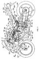
- FIG. 1 is a side elevational view of a motorcycle showing a first embodiment.
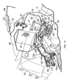
- FIG. 2 is an enlarged fragmentary view of FIG. 1.
- FIG. 3 is a plan view of a front portion of a vehicle frame.
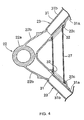
- FIG. 4 is an enlarged cross-sectional view of the front portion of the vehicle frame, taken along line 4-4 of FIG. 2.
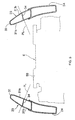
- FIG. 5 is a cross-sectional view taken along line 5-5 of FIG. 2.
- FIG. 6 is an enlarged view as viewed in the
direction indicated by the
arrow 6 in FIG. 1. - FIG. 7 is an enlarged view as viewed in the
direction indicated by the
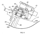
arrow 7 in FIG. 1. - FIG. 8 is a cross-sectional view taken along line 8-8 of FIG. 7.
- FIG. 9 is a cross-sectional view taken along line 9-9 of FIG. 2.
- FIG. 10 is a cross-sectional view taken along line 10-10 of FIG. 6.
- FIG. 11 is an enlarged fragmentary view of FIG. 6.
- FIG. 12 is a view as viewed in the direction
indicated by the
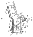
arrow 12 in FIG. 11. - FIG. 13 is a transverse plan view, partly cut away,
as viewed in the direction indicated by the
arrow 13 in FIG. 12. - FIG. 14 is a cross-sectional view taken along line 14-14 of FIG. 13.
- FIG. 15 is an enlarged view as viewed in the direction indicated by the arrow 15 in FIG. 12.
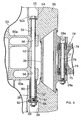
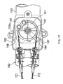
- FIG. 16 is an enlarged cross-sectional view taken along line 16-16 of FIG. 2.
- FIG. 17 is a cross-sectional view taken along line 17-17 of FIG. 16.
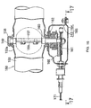
- FIG. 18 is an enlarged cross-sectional view taken along line 18-18 of FIG. 2.
- FIG. 19 is a cross-sectional view taken along line 19-19 of FIG. 18.
- FIG. 20 is a cross-sectional view showing a second embodiment corresponding to FIG. 18.
- FIG. 21 is a cross-sectional view showing a third embodiment corresponding to FIG. 18.
-
- FIGS. 1 through 19 show a first embodiment of the present invention.
- As shown in FIGS. 1 through 3, the motorcycle has a vehicle frame F including a
head pipe 22 by which afront fork 21 rotably supporting a front wheel WF is steerably supported, a pair of left and rightmain frames 23 extending rearwardly and downwardly from thehead pipe 22, a pair of left andright engine hangers 24 welded to thehead pipe 22 and front portions of themain frames 23 and extending downwardly from themain frames 23,joint pipes 25 joiningsupport plates 33 mounted on lower portions of theengine hangers 24 and rear portions of themain frames 23, a pair of left andright pivot plates 26 extending downwardly from the rear portions of themain frames 23, afirst cross pipe 27 disposed between front portions of themain frames 23, asecond cross pipe 28 disposed between upper portions of thepivot plates 26, athird cross pipe 29 disposed between lower portions of thepivot plates 26, and a pair of left andright seat rails 30 extending rearwardly and upwardly and joined to rear portions of themain frames 23. - In FIG. 4, the
head pipe 22 has, integrally therewith, acylindrical portion 22a by which thefront fork 21 is steerably supported and a pair of left andright gussets 22b extending rearwardly and downwardly from thecylindrical portion 22a. Themain frames 23 include thegussets 22b,pipes 31 having front ends welded to thegussets 22b, andpipes 26a integral with thepivot plates 26 and welded to rear ends of thepipes 31. - In order to install the
first cross pipe 27 between the front portions of themain frames 23,attachment holes 32 are coaxially provided in inner side walls of themain frames 23, and thefirst cross pipe 27 has its opposite ends inserted in therespective attachment holes 32 and welded to the inner side walls of themain frames 23. - The
gussets 22b of thehead pipe 22 haveintegral extensions 22c disposed inwardly of front inner side walls of thepipes 31 and extending rearwardly, theextensions 22c serving as front inner side walls of themain frames 23. Theattachment holes 32 are provided in therespective extensions 22c, and the opposite ends of thefirst cross pipe 27 are inserted in therespective attachment holes 32 in confronting relation to the front inner side walls of thepipes 31. The opposite ends of thefirst cross pipe 27 are welded to outer surfaces of theextensions 22c. - Referring also to FIG. 5, the
pipes 31 are formed from an ingot of aluminum alloy into a transverse outer profile in the shape of a prismatic tube by a conventional known extrusion or drawing process. Thepipes 31 haveintegral ribs 34 extending between vertically intermediate inner surfaces thereof and dividing the interior of thepipes 31 into upper and lower regions. Thepipes 31 have lower portions to which theengine hangers 24 are welded and which are open downwardly, i.e., toward theengine hangers 24. - The
pipes 31 are in the shape of a vertically elongate prismatic shape having respectiveinner side walls 31a, which are flat substantially the full vertical length thereof, and respectiveouter side walls 31b extending substantially along theinner side walls 31a. Thepipes 31 are bent in a plane PL perpendicular to theinner side walls 31a such that thepipes 31 have respective longitudinally intermediate portions, which are outwardly projected. Thebent pipes 31 are inclined progressively toward each other in the upward direction and are joined to therespective gussets 22b of thehead pipe 22. - In FIG. 6, the
front fork 21 includescushion units 35 extending vertically on respective left and right sides of the front wheel WF, abottom bridge 36 interconnecting thecushion units 35 above the front wheel WF, and atop bridge 37 interconnecting upper portions of thecushion units 35. The front wheel WF has anaxle 38 supported between the lower ends of thecushion units 35. - As also shown in FIGS. 7 and 8, a
steering shaft 39, which extends parallel to thecushion units 35, is disposed between thebottom bridge 36 and thetop bridge 37 behind a central region between thecushion units 35. Thesteering shaft 39 is turnably supported by atubular portion 22a of thehead pipe 22. - Left and right bar-
shaped steering handles 40 are connected to the respective upper ends of thecushion units 35 above thebottom bridge 36. Asteering damper 41 is disposed between the front end of the vehicle frame F, i.e., thehead pipe 22, and thetop bridge 37 of thefront fork 21. - The
steering damper 41 includes ahousing 42 incorporating a hydraulic damping mechanism (not shown) and fixedly supported on thehead pipe 22, aturn shaft 43 disposed above thesteering shaft 39 coaxially therewith and turnably supported on thehousing 42, anarm 44 having a proximal end fixed to theturn shaft 43 and extending forwardly, aresilient roller 45 supported rotably on the distal end of thearm 44, and arecess 46 provided in an upper central surface of thetop bridge 37 and held in fitting frictional contact with the outer circumferential surface of theresilient roller 45. - Rotational vibrations about the
steering shaft 39, which are transmitted from the front wheel WF to thetop bridge 37, are attenuated by the hydraulic damping mechanism in thehousing 42 through thearm 44. - Referring back to FIG. 2, the engine E, which is a multi-cylinder engine having four cylinders, for example, arrayed parallel transversely across the vehicle frame F, has an
engine body 50 supported on lower portions of theengine hangers 24 and upper and lower portions of thepivot plates 26. - The
engine body 50 is fastened to the lower portions of theengine hangers 24 by a pair of left andright bolts 51. - In FIG. 9, for supporting the
engine body 50 on the lower portions of thepivot plates 26 that are disposed on the opposite sides of theengine body 50, aninsertion hole 53 for inserting amount bolt 52 therethrough and a first engagingsurface 54 surrounding the outer end of theinsertion hole 53 are provided in a lower portion of one of the pivot plates 26 (in the present embodiment, thepivot plate 26 positioned on the right side when viewed forwardly in the direction of travel of the motorcycle). Specifically, theinsertion hole 53, which is open at an inner side surface of thepivot plate 26, and afirst entry hole 55, which is larger in diameter than theinsertion hole 53 and which is open at an outer side surface of thepivot plate 26, are provided in the lower portion of thepivot plate 26. The firstengaging surface 54 is formed as an annular step facing thefirst entry hole 55 between the outer end of theinsertion hole 53 and the inner end of thefirst entry hole 55. - The
engine body 50 has a pair ofintegral support arms 50a disposed between thepivot plates 26 and spaced from each other in the axial direction of themount bolt 52. Thesupport arms 50a have respective throughholes 56 provided coaxially therein for the insertion of themount bolt 52 therethrough. - The lower portion of the
other pivot plate 26 has a threadedhole 57 coaxial with theinsertion hole 53 and a secondengaging surface 58 surrounding the outer end of the threadedhole 57. Specifically, the threadedhole 57, which is open at an inner side surface of thepivot plate 26, and asecond entry hole 59 which is larger in diameter than the threadedhole 57 and which is open at an outer side surface of thepivot plate 26, are provided in the lower portion of thepivot plate 26. The secondengaging surface 58 is formed as an annular step facing thesecond entry hole 59 between the outer end of the threadedhole 57 and the inner end of thesecond entry hole 59. - A
tubular bolt 60 is threaded in the threadedhole 57 and has an end held in abutment against theengine body 50. Specifically, while one of thesupport arms 50a is being held in abutment against an inner side surface of one of thepivot plates 26, thetubular bolt 60 is threaded in the threadedhole 57 with the end thereof held in abutment against theother support arm 50a. Atubular retaining bolt 61 is also threaded in the threadedhole 57 in abutment against the other end of thetubular bolt 60 to prevent thetubular bolt 60 from working loose. Thetubular bolt 60 and the retainingbolt 61 are threaded in the threadedhole 57 with the other end of thetubular bolt 60 and the retainingbolt 61 being positioned inwardly of the second engagingsurface 58 while theengine body 50 is being sandwiched between the inner side surface of the one of thepivot plates 26 and the end of thetubular bolt 60. - The
mount bolt 52 is inserted through theinsertion hole 53, the throughholes 56 in theengine body 50, thetubular bolt 60, the retainingbolt 61, and the threadedhole 57. Themount bolt 52 has a larger-diameter head 52a on an end thereof, which engages with one of the first and second engagingsurfaces nut 63 engaging the other of the first and second engagingsurfaces mount bolt 52. In the present embodiment, the other end of themount bolt 52 whose larger-diameter head 52a engages with the first engagingsurface 54 projects from the threadedhole 57, and thenut 63, which is threaded over the other end of themount bolt 52 that projects from the threadedhole 57, engages with the second engagingsurface 58 with awasher 62 interposed therebetween. - A structure by which the
engine body 50 is supported on the upper portions of thepivot plates 26 is basically the same as the structure by which theengine body 50 is supported on the lower portions of thepivot plates 26, and will not be described in detail below. - A
swing arm 66 has a front end swingably supported by asupport shaft 67 on vertically intermediate portions of thepivot plates 26. A rear wheel WR has anaxle 68 rotatably supported on the rear end of theswing arm 66. - The
engine body 50 incorporates therein a transmission whoseoutput shaft 69 transmits power through a chain transmitting means 70 to the rear wheel WR. The chain transmitting means 70 includes adrive sprocket 71 fixed to theoutput shaft 69, a drivensprocket 72 fixed to the rear wheel WR, and anendless chain 73 trained around thesprockets - A
link mechanism 74 is disposed between thethird cross pipe 29 interconnecting the lower portions of thepivot plates 26 and theswing arm 66. Thelink mechanism 74 includes afirst link 75 having an end joined to thethird cross pipe 29 so as to be rotable about a firstjoint shaft 77 parallel to thesupport shaft 67, and asecond link 76 joined to a lower portion of theswing arm 66 so as to be rotable about a secondjoint shaft 80 parallel to the firstjoint shaft 77 and joined to the other end of thefirst link 75 by a thirdjoint shaft 81 parallel to the first and secondjoint shafts - The
third cross pipe 29 has a pair of integral shaft supports 29a projecting rearwardly from two locations that are longitudinally spaced from each other thereon. Acollar 78 is mounted on the firstjoint shaft 77 that is disposed between the shaft supports 29a, and thefirst link 75 has an end supported on thecollar 78 by a pair ofroller bearings 79. - The other end of the
first link 75 is joined to a rear portion of thesecond link 76 by the thirdjoint shaft 81. Arear cushion unit 82 has an upper end coupled to abracket 66a mounted on a front portion of theswing arm 66 and a lower end coupled to a front portion of thesecond link 76 by a fourthjoint shaft 83. - Referring also to FIG. 10, an
air cleaner 87 for purifying air to be supplied to the engine E is disposed above acylinder head 86 of theengine body 50 behind thehead pipe 21 of the vehicle frame F. Theair cleaner 87 has rear and upper portions covered with afuel tank 88, which is mounted on themain frames 23 of the vehicle frameF. A radiator 89 is disposed forwardly of theengine body 50. As shown in FIG. 2, amain seat 90 for the rider to ride on is supported on the seat rails 30 behind thefuel tank 88. Apillion seat 91 for a passenger to ride on is supported on the seat rails 30 at a position spaced rearwardly from themain seat 90. -
Straight intake passages 92 for guiding purified air from theair cleaner 87 above thecylinder head 86 are connected to an upper side wall of thecylinder head 86 in communication with the respective cylinders. Theintake passages 92 includerespective funnels 93 having upper open ends projecting into theair cleaner 87, andrespective throttle bodies 94 connected to the respective lower ends of thefunnels 93. Thethrottle bodies 94 are connected to the upper side wall of thecylinder head 86 with aninsulator 95 interposed therebetween. - The
air cleaner 87 includes a cylindricalcleaner element 97 fixedly housed in acleaner case 96, with apurification chamber 98 provided around thecleaner element 97 in thecleaner case 96 for being supplied with air that has been purified by passing through thecleaner element 97. The funnels 93 on the upper ends of theintake passages 92 are installed parallel to each other on thecleaner case 96 so as to be open into thepurification chamber 98. -
First injectors 100 for injecting fuel when the engine E rotates at a high speed are mounted on thecleaner case 96 of theair cleaner 87 for the respective cylinders of the engine E. Thefirst injectors 100 are disposed forwardly of central lines C1 of theintake passages 92, and are mounted on thecleaner case 96 so as to have their axes inclined to the central lines C1. A fuel pump (not shown) is disposed in thefuel tank 88 for supplying fuel to thefirst injectors 100. - The
fuel tank 88 has afuel inlet port 101 provided in a front portion thereof. Thefirst injectors 100 are disposed forwardly of a central line C2 of thefuel inlet port 101. Thefirst injectors 100 are mounted on thecleaner case 96 such that their upper portions are disposed forwardly of points P of intersection between the central lines C1, C2 on a projection onto a plane parallel to the central line C2 of thefuel inlet port 101 and the central lines C1 of theintake passages 92. - The
throttle bodies 94 in theintake passages 92 house respective throttle valves (not shown) for controlling the amount of intake air flowing through theintake passages 92. Athrottle drum 102 coupled to the throttle valves is disposed laterally of thethrottle bodies 94. -
Second injectors 103 for ejecting fuel supplied from the fuel pump in thefuel tank 88 depending on the operating state of the engine E are disposed closer to the engine E than the throttle valves rearwardly and laterally of thethrottle bodies 94. - Referring also to FIGS. 11 through 14, an
intake duct 105 for introducing external air into theair cleaner 87 is disposed below thehead pipe 21 at the front end of the vehicle frame F and extends forwardly from theair cleaner 87. Theintake duct 105 has a rear end projecting into and fixed to a lower portion of thecleaner case 96 for introducing external air into thecleaner element 97 in theair cleaner 87. - The
intake duct 105 includes a rearmain duct body 106 having a substantially triangular transverse cross-sectional shape including a transversely central portion raised upwardly and a lower open portion, a frontmain duct body 107 having substantially the same transverse cross-sectional shape as the rearmain duct body 106 and joined to a front portion of the rearmain duct body 106, and alower lid plate 108 closing the lower open ends of the rear and frontmain duct bodies intake duct 105 has a rear portion inclined upwardly in the rearward direction as viewed in side elevation. Thelower lid plate 108 is fastened to the rearmain duct body 106 by a plurality ofscrews 109 and also fastened to the frontmain duct body 107 by a plurality ofscrews 110. - Support stays 111 are fixed by
screws 112 to front lower surfaces of thepipes 31, which serve as part of themain frames 23 of the vehicle frameF. Attachment bosses 113 disposed on lower portions of opposite front sides of theintake duct 105 are fastened to the support stays 111 byscrews 114, thus supporting the front portion of theintake duct 105 on the vehicle frameF. Positioning pins 113a inserted in the support stays 111 project on theattachment bosses 113. - The
radiator 89 is disposed below theintake duct 105.Stays 115 extend upwardly from opposite sides of theradiator 89. Welded nuts 116 are fixed to the support stays 111, andbolts 117 inserted through thestays 115 and the support stays 111 are threaded through the weldednuts 116, thus supporting theradiator 89 on the vehicle frame F. - The
lower lid plate 108 of theintake duct 105 has a pair ofintegral partition walls 118 held in abutment against lower surfaces of upper portions of the rear and frontmain duct bodies intake duct 105, there are provided afirst intake passage 119 whose transversely central portion is disposed on a transversely central line C3 of the front wheel WF and a pair of left and rightsecond intake passages 120 disposed one on each side of thefirst intake passage 119, by thepartition walls 118 between thefirst intake passage 119 and thesecond intake passages 120. Thefirst intake passage 119 has a flow passage area greater than the total flow passage area of thesecond intake passages 120. - The
partition walls 118 have front portions inclined so as to be progressively spaced away from each other in the forward direction. Thepartition walls 118 have front ends held in abutment against inner surfaces of the opposite side walls of the frontmain duct body 107. Thefirst intake passage 119 has a front portion, which is open forwardly at the front end of theintake duct 105, so as to occupy an entire end opening of theintake duct 105. Thesecond intake passages 120 have respectivefront end openings 120a provided in the front end of theintake duct 105 so as to be open in a direction different from the direction in which the front end of thefirst intake passage 119 is open. In the present embodiment, thefront end openings 120a are provided in the frontmain duct body 107 so as to be open upwardly on both left and right sides of the front end of thefirst intake passage 119. - The front end of the
intake duct 105 is of a substantially triangular shape as viewed from its front side. The front end of theintake duct 105 has an upper edge extending along the lower edge of a junction between thehead pipe 21 and themain frames 23 and a lower edge extending along the upper portion of theradiator 89. Agrill 121 is mounted on the front end of theintake duct 105. - The
grill 121 includes aframe member 122 complementary in shape to the front end opening edge of theintake duct 105 and amesh member 123 having a peripheral edge supported on theframe member 122.Baffle plates 122a are integrally formed with theframe member 122 at respective positions spaced from thefront end openings 120a of thesecond intake passages 120. Thebaffle plates 122a are fastened to front opposite sides of the frontmain duct body 107 of theintake duct 105 byscrews 124. Positioning pins 125 for preventing a lower portion of theframe member 122 from being dislodged from the front end of theintake duct 105 project from the front end of thelower lid plate 108 and are inserted into the lower portion of theframe member 122. - In the
first intake passage 119, there is disposed a first butterflyintake control valve 126, which is controlled depending on the rotational speed of the engine E, for closing thefirst intake passage 119 when the engine E operates in a low rotational speed range and opening thefirst intake passage 119 when the engine E operates in a high rotational speed range. In thesecond intake passages 120, there are disposed second butterflyintake control valves 127, which are controlled depending on the rotational speed of the engine E, for opening thesecond intake passages 120 when the engine E operates in a low rotational speed range and closing thesecond intake passages 120 when the engine E operates in a high rotational speed range. The first butterflyintake control valve 126 and the second butterflyintake control valves 127 are fixed in common to avalve shaft 128. Theshaft 128 has an axis perpendicular to the direction in which air flows through thefirst intake passage 119 and is turnably supported in theintake duct 105. - The
valve shaft 128 is rotatably supported on thepartition walls 118 in regions of theintake duct 105, which correspond to thefront end openings 120a of thesecond intake passages 120. Of thescrews 110 that fasten the frontmain duct body 107 to thelower lid plate 108, two pairs ofscrews 110 are threaded into thepartition walls 118 at positions one on each side of thevalve shaft 128. - The first
intake control valve 126, which changes the flow passage area of thefirst intake passage 119, is fixed to thevalve shaft 128 such that it is inclined upwardly in the rearward direction when it closes thefirst intake passage 119, as shown in FIG. 14. The firstintake control valve 126 has a portion above thevalve shaft 128, which has an area greater than the area of a portion of the firstintake control valve 126 beneath thevalve shaft 128. When the firstintake control valve 126 opens thefirst intake passage 119, it lies substantially horizontally as indicated by the two-dot-and-dash lines in FIG. 14 to impose a minimum resistance on air flowing through thefirst intake passage 119. - The second
intake control valves 127, which change the flow passage areas of thesecond intake passages 120, are fixed to thevalve shaft 128 such that they open thefront end openings 120a of thesecond intake passages 120 when the firstintake control valve 126 closes thefirst intake passage 119. - A
turn shaft 130 parallel to thevalve shaft 128 is disposed rearwardly of thevalve shaft 128 and below theintake duct 105. Theturn shaft 130 is turnably supported by a plurality ofbearings 129 projecting from a lower surface of theintake duct 105, i.e., a lower surface of thelower lid plate 108. - An
arm 130a is mounted on a portion of theturn shaft 130 corresponding to thefirst intake passage 119. Ajoint rod 131 which extends through the lower portion of theintake duct 105, i.e., thelower lid plate 108, has an end connected to a portion of the firstintake control valve 126 as it is closed above thevalve shaft 128 and an opposite end connected to thearm 130a. When theturn shaft 130 is turned about its own axis, the firstintake control valve 126 is turned between the closing side indicated by the solid lines in FIG. 14 and the opening side indicated by the two-dot-and-dash lines in FIG. 14. - Return springs 132 for exerting spring forces to bias the
turn shaft 130 and thevalve shaft 128 in a direction to bring the firstintake control valve 126 into the closing side are disposed between the opposite ends of theturn shaft 130 and theintake duct 105. Thejoint rod 131 movably extends through a throughhole 133 provided in thelower lid plate 108. The throughhole 133 is elongate in the fore-and-aft direction to allow thejoint rod 131 extending through thelower lid plate 108 to move in the fore-and-aft direction as thearm 130a is turned in unison with theturn shaft 130. - A driven
pulley 134 is fixed to an end of theturn shaft 130. To the drivenpulley 134, there is transmitted rotational power through afirst transmission wire 135 from anactuator 141, which is supported on one of thesupport plates 33 in rear portions of themain frames 23 and disposed on the left side of an upper portion of theengine body 50. - As shown in FIG. 15, the
actuator 141 includes a reversible electric motor and a speed-reduction mechanism for reducing the rotational speed of output power from the electric motor. Theactuator 141 is mounted on a pair ofbrackets 33a of one of thesupport plates 33 of the vehicle frame F by abolt 143 withresilient members 142 interposed therebetween. Theactuator 141 has anoutput shaft 144 on which there is fixedly mounted adrive pulley 145 having a first small-diameter wire groove 146 and second and third large-diameter wire grooves - The
first transmission wire 135 for transmitting rotational power to the drivenpulley 134 on theintake duct 105 has an end trained around and engaged with thefirst wire groove 146. - An
electronic control unit 149 is connected to theactuator 141, and controls operation of theactuator 141 depending on the rotational speed of the engine, which is input from a sensor (not shown). - Referring back to FIGS. 1 and 2, an
exhaust system 150 connected to the engine E includesindividual exhaust pipes 151 connected to a lower portion of a front side wall of thecylinder head 86 of theengine body 50, a pair of firstjoint exhaust pipes 152 to each of which a pair ofindividual exhaust pipes 151 is connected in common, a single secondjoint exhaust pipe 153 to which the firstjoint exhaust pipes 152 are connected in common, with afirst exhaust muffler 154 disposed in an intermediate portion thereof, and asecond exhaust muffler 155 connected to a downstream end of the secondjoint exhaust pipe 153. - The
individual exhaust pipes 151 extend downwardly from the front of theengine body 50, and the firstjoint exhaust pipes 152 extend substantially in the fore-and-aft direction below theengine body 50. The secondjoint exhaust pipe 153 is curved upwardly between the rear wheel WR and theengine body 50 and directed from below theengine body 50 to the right of the vehicle body, and then extends rearwardly above the rear wheel WR. Thefirst exhaust muffler 154 is disposed in the rising portion of the secondjoint exhaust pipe 153, and a rear end outlet of theexhaust system 150, i.e., a downstream end of thesecond exhaust muffler 155, is disposed above theaxle 68 of the rear wheel WR. - As also shown in FIGS. 16 and 17, the second
joint exhaust pipe 153, which serves as part of theexhaust system 150, has a larger-diameter portion 153a positioned forwardly and upwardly of theaxle 68 of the rear wheel WR. Anexhaust control valve 156 is disposed in the larger-diameter portion 153a for changing the flow passage area in the secondjoint exhaust pipe 153 depending on the rotational speed of the engine E to control exhaust pulsations in theexhaust system 150. - When the engine E is in low and medium rotational speed ranges, the
exhaust control valve 156 is operated into a closing side for increasing the output power of the engine E based on an exhaust pulsating effect in theexhaust system 150. When the engine E is in a high rotational speed range, theexhaust control valve 156 is operated into an opening side for increasing the output power of the engine E by reducing the resistance to the exhaust gas flow in theexhaust system 150. Theexhaust control valve 156 is fixed to avalve shaft 157, which is turnably supported in the larger-diameter portion 153a of the secondjoint exhaust pipe 153. - The
valve shaft 157 has an end supported by aseal 159 in a bottomed cylindrical bearinghousing 158 that is fixed to the larger-diameter portion 153a. The other end of thevalve shaft 157 projects from the larger-diameter portion 153a with aseal 160 interposed between the other end of thevalve shaft 157 and the larger-diameter portion 153a. A drivenpulley 161 is fixed to the projecting end of thevalve shaft 157. Areturn spring 162 for urging thevalve shaft 157 in a direction to open theexhaust control valve 156 acts between thevalve shaft 157 and the larger-diameter portion 153a. - The end of the
valve shaft 157 projecting from the larger-diameter portion 153a, the drivenpulley 161, and thereturn spring 162 are housed in acase 165, which includes a cup-shapedmain case body 163 fixed to the larger-diameter portion 153a and alid plate 164 fastened to themain case body 163 in covering relation to an open end of themain case body 163. - A
limit arm 166 having a distal end projecting from the outer circumferential edge of the drivenpulley 161 is fixed to thevalve shaft 157 with thecase 165. On an inner surface of themain case body 163 of thecase 165, there are disposed aclosing stopper 167 for engaging the distal end of thelimit arm 166 to limit the end of turning to the closing side of thevalve shaft 157, i.e., thedischarge control valve 156, and anopening stopper 168 for engaging the distal end of thelimit arm 166 to limit the end of turning to the opening side of thevalve shaft 157, i.e., thedischarge control valve 156. - A
second transmission wire 171 for operating thedischarge control valve 156 into the closing side at the pulling time has an end trained around and engaged with the drivenpulley 161. Athird transmission wire 172 for operating thedischarge control valve 156 into the opening side at the pulling time also has an end trained around and engaged with the drivenpulley 161. As shown in FIG. 15, the other end of thesecond transmission wire 171 is trained around and engaged with thesecond wire groove 147 of thedrive pulley 145 of theactuator 141 in a direction opposite to the direction in which thefirst transmission wire 135 is trained. The other end of thethird transmission wire 172 is trained around and engaged with thethird wire groove 148 of thedrive pulley 144 in the same direction as the direction in which thefirst transmission wire 135 is trained. - Therefore, the
actuator 141 for actuating theexhaust control valve 156 that is controlled depending on the rotational speed of the engine E is coupled to the firstintake control valve 126 for turning the firstintake control valve 126 in theintake duct 105. - Of the second
joint discharge pipe 153, the larger-diameter portion 153a where theexhaust control valve 156 is disposed should desirably be disposed below themain seat 90 for avoiding, as much as possible, unwanted external forces applied from above to the second andthird transmission wires case 165 is disposed so as to be exposed outwardly as viewed in side elevation in order to facilitate impingement thereon of the running airflow. - The
actuator 141 should desirably be disposed rearwardly and upwardly of theengine body 50 at such a position that the distance between the actuator 141 and thevalve shaft 128 in theintake duct 105 and the distance between the actuator 141 and thevalve shaft 157 of theexhaust valve 156 are substantially equal to each other. In this manner, any obstacles between the drivenpulley 161 of theexhaust control valve 156 and theactuator 141 are minimized to allow the second andthird transmission wires pulley 161 and theactuator 141, to be installed with ease. - In FIGS. 18 and 19, the first
joint exhaust pipes 152, which serve as part of theexhaust system 150, have respective larger-diameter portions 152a positioned below theengine body 50. Acatalytic body 175 is housed in each of the larger-diameter portions 152a. With thecatalytic body 175 disposed below theengine body 50, the exhaust gas discharged from thecylinder head 86 can pass through thecatalytic body 175 while the exhaust gas is kept at a relatively high temperature. - The
catalytic body 175 includes acylindrical case 176 and acatalyst support 177, which is of a cylindrical shape for allowing the exhaust gas to pass therethrough, thecatalyst support 177 being housed in thecylindrical case 176 and having an end disposed inwardly of an end of thecase 176. Thecase 176 is made of a material different from the firstjoint exhaust pipe 152. For example, the firstjoint exhaust pipe 152 is made of titanium, and thecase 176 and thecatalyst support 177 of thecatalytic body 175 are made of stainless steel. - A
bracket 178 made of the same material, e.g., titanium, as the firstjoint exhaust pipe 152 is welded to an inner circumferential surface of the larger-diameter portions 152a of the firstjoint exhaust pipe 152. Thebracket 178 includes alarge ring 178a fitted in the larger-diameter portions 152a in surrounding relation to an end of thecase 176, asmall ring 178b contiguous to thelarge ring 178a with the end of thecase 176 being fitted in thesmall ring 178b, and a plurality of, e.g., four, circumferentially equally spacedextension arms 178c extending from thesmall ring 178b in a direction opposite to thelarge ring 178a. - The larger-
diameter portions 152a has a plurality of circumferentially spaced throughholes 179 provided therein so as to face the outer circumferential surface of thelarge ring 178a. Thelarge ring 178a is welded to the larger-diameter portions 152a at the throughholes 179, thus securing thebracket 178 to the larger-diameter portions 152a of the firstjoint exhaust pipe 152. Theextension arms 178c are crimped on the end of thecase 176 of thecatalytic body 175. Thebracket 178 welded to the larger-diameter portions 152a of the firstjoint exhaust pipe 152 is crimped on the end of thecase 176, which projects from the end of thecatalyst support 177. - A
ring 180 including a stainless mesh is spot-welded to the outer surface of the other end of thecase 176 of thecatalytic body 175. Thering 180 is interposed between the larger-diameter portions 152a of the firstjoint exhaust pipe 152 and the other end of thecase 176, allowing the other end of thecatalytic body 175 whose opposite end is fixed to the larger-diameter portions 152a by thebracket 178 to slide by way of thermal expansion. Therefore, stresses caused due to thermal expansion of thecatalytic body 175 are prevented from being applied between the fixed end of thecatalytic body 175 and the larger-diameter portions 152a. - Referring again to FIG. 1, the front area of the
head pipe 22 is covered with afront cowl 181 made of synthetic resin. Front opposite side areas of the vehicle body are covered, with acentral cowl 182 made of synthetic resin which is contiguous to thefront cowl 181. Alower cowl 183 made of synthetic resin, which covers opposite sides of theengine body 50, is contiguous to thecentral cowl 182. Rear portions of the seat rails 30 are covered with arear cowl 184. - An upper area of the front wheel WF is covered with a
front fender 185 mounted on thefront fork 21. Arear fender 186 covering an upper area of the rear wheel WR is mounted on the seat rails 30. - Operation of the present embodiment will be described below. The
first cross pipe 27 is disposed between the front portions of the pair of left and rightmain frames 23 joined to theheat pipe 22 that is positioned at the front end of the vehicle frame F. The attachment holes 32 are coaxially provided in the inner side walls of the front portions of themain frames 23, and thefirst cross pipe 27 has its opposite ends inserted in the respective attachment holes 32 and welded to the inner side walls of the main frames 23. By changing the distance by which the opposite ends of thefirst cross pipe 27 are inserted into the attachment holes 32, dimensional errors between the pair of left and rightmain frames 23 and an error of the axial length of thefirst cross pipe 27 can be absorbed, allowing the opposite ends of thefirst cross pipe 27 to be reliably welded to the inner side walls of the main frames 23. - The
head pipe 22 has thecylindrical portion 22a by which thefront fork 21 is steerably supported and the pair of left andright gussets 22b extending rearwardly and downwardly from thecylindrical portion 22a. Themain frames 23 include at least thegussets 22b and thepipes 31 welded respectively to thegussets 22b. Thegussets 22b have theintegral extensions 22c disposed inwardly of the front inner side walls of thepipes 31 and extending rearwardly, theextensions 22c serving as the front inner side walls of the main frames 23. The attachment holes 32 for inserting the opposite ends of thefirst cross pipe 27 therein in confronting relation to the front inner side walls of thepipes 31 are provided in therespective extensions 22c, and the opposite ends of thefirst cross pipe 27 are welded to the outer surfaces of theextensions 22c. Since the opposite ends of thefirst cross pipe 27 are welded to the outer surfaces of theextensions 22c, which are integral with thegussets 22b that serve as part of themain frames 23, thefirst cross pipe 27 can easily be welded to themain frame 23, and the appearance of the welded structure is fine as the welded regions are concealed from external view. - The
pipes 31 are in the shape of the vertically elongate prismatic shape having the respectiveinner side walls 31a, which are flat substantially the full vertical length thereof, and the respectiveouter side walls 31b extending substantially along theinner side walls 31a. Thepipes 31 can be bent with ease because they are bent in the plane PL perpendicular to theinner side walls 31a. - The
pipes 31 are inclined progressively toward each other in the upward direction and are joined to therespective gussets 22b of thehead pipe 22. Accordingly, with a simple structure of theinclined pipes 31, the space between the lower portions of thepipes 31 is widened to provide a sufficient installation space for the engine E, and the space between the upper portions of thepipes 31 is reduced to make the knees of the rider less liable to contact thepipes 31. - For supporting the
engine body 50 on the upper and lower portions of thepivot plates 26 in the vehicle frame F, theinsertion hole 53 for inserting themount bolt 52 therethrough and the first engagingsurface 54 surrounding the outer end of theinsertion hole 53 for engaging the larger-diameter head 52a on one end of thebolt 52 are provided in one of thepivot plates 26, and theother pivot plate 26 has the threadedhole 57 coaxial with theinsertion hole 53 and the second engagingsurface 58 surrounding the outer end of the threadedhole 57. Thetubular bolt 60 is threaded in the threadedhole 57 with the other end of thetubular bolt 60 being positioned inwardly of the second engagingsurface 58 while theengine body 50 is being sandwiched between the end of thetubular bolt 60 and the inner side surface of the one of thepivot plates 26. Thenut 63 capable of engaging the engagingsurface 58 is threaded over the other end of themount bolt 52, which is inserted in theinsertion hole 53, theengine body 50, thetubular bolt 60, and the threadedhole 57 and projects from the threadedhole 57. - With the above structure by which the
engine body 50 is supported on the vehicle frame F, it is possible, by adjusting the position where thetubular bolt 60 is threaded into the threadedhole 57, to sandwich theengine body 50 reliably between one of thepivot plates 26 and one end of thetubular body 60 while absorbing a dimensional error between thepivot plates 26 and a dimensional error in the transverse direction of theengine body 50. Since the larger-diameter head 52a at one end of themount bolt 52 engages with the first engagingsurface 54 of one of thepivot plates 26, and thenut 63, which is threaded over the other end of themount bolt 52, engages with the second engagingsurface 58 of theother pivot plate 26, the opposite ends of themount bolt 52 can be fastened to the vehicle frame F so as to be firmly axially positioned, thus increasing the rigidity with which theengine body 50 is supported. - The
tubular retaining bolt 61, which is held in abutment against the other end of thetubular bolt 60, is threaded in the threadedhole 57 so as to be positioned inwardly of the second engagingsurface 58. Consequently, the retainingbolt 61 is held in contact with the other end of thetubular bolt 60 for effectively preventing thetubular bolt 60 from working loose. - The
straight intake passages 92 for guiding purified air from theair cleaner 87 disposed above thecylinder head 86 are connected to the upper side wall of thecylinder head 86 of theengine body 50. Thefirst injectors 100 for injecting fuel into theintake passages 92 from above are mounted on thecleaner case 96 of theair cleaner 87, and thefuel tank 88 is disposed in covering relation to rear and upper areas of theair cleaner 87. Thefirst injectors 100 are disposed forwardly of the central lines C1 of theintake passages 92. - Specifically, the
first injectors 100 are disposed at a position offset forwardly from the central lines C1 of theintake passages 92. On the central lines C1 of theintake passages 92, the bottom wall of thefuel tank 88 can be placed in a relatively low position while avoiding interference with thefirst injectors 100. Therefore, it is possible for thefuel tank 88 to have a sufficient capacity. - The
first injectors 100 are disposed forwardly of the central line C2 of thefuel inlet port 101 that is provided in the front portion of thefuel tank 88. As thefirst injectors 100 do not interfere with thefuel tank 88 on the central line C2 of thefuel inlet port 101, thefuel inlet port 101 can be placed in a lower position. In addition, thefirst injectors 100 are mounted on thecleaner case 96 of theair cleaner 87 such that their upper portions are disposed forwardly of the points P of intersection between the central lines C1, C2 on the projection onto the plane parallel to the central line C2 of thefuel inlet port 101 and the central lines C1 of theintake passages 92. Therefore, the bottom wall of thefuel tank 88 can be placed in a relatively low position forwardly of the central line C2 of thefuel inlet port 101, making it possible for thefuel tank 88 and theair cleaner 87 to have a sufficient capacity, and also for a fuel supply nozzle to be inserted easily into thefuel inlet port 101 when the fuel is to be supplied to thefuel tank 88. - The
second injectors 103 for ejecting the fuel into theintake passages 92 are disposed rearwardly and laterally of thethrottle bodies 94 in theintake passages 92. Thefirst injectors 100, which are supplied with the fuel at a relatively low temperature and eject the fuel from above theintake passages 92 to contribute to an increase in the output power of the engine E, and thesecond injectors 103, which are capable of injecting the fuel in reaction with good response to the operation of the engine E, can be placed using the installation space of theintake passages 92 effectively in a well balanced fashion. - The
intake duct 105, which extends forwardly from theair cleaner 87 disposed on thehead pipe 22 at the front end of the vehicle frame F, is disposed below thehead pipe 22. In theintake duct 105, thefirst intake passage 119 whose transversely central portion is disposed on the transversely central line C3 of the front wheel WF and the pair of left and rightsecond intake passages 120 disposed one on each side of thefirst intake passage 119 are provided with the flow passage area of thefirst intake passage 119 being greater than the total flow passage area of thesecond intake passages 120. The firstintake control valve 126, which closes thefirst intake passage 119 when the engine E operates in a low rotational speed range and opens thefirst intake passage 119 when the engine E operates in a high rotational speed range, is disposed in thefirst intake passage 119. - With the above structure of the
intake duct 105, when the engine E is in a low rotational speed range, i.e., when motorcycle is running at a low speed on a road from which water or foreign matter tends to be stirred up, since thefirst intake passage 119 whose transversely central portion is disposed on the transversely central line C3 of the front wheel WF is closed, such water or foreign matter is prevented as much as possible from entering theair cleaner 87. When the engine E is in a high rotational speed range, since water or foreign matter from the road is hardly stirred up due to the running airflow, such water or foreign matter is also prevented as much as possible from entering theair cleaner 87. Furthermore, as thefirst intake passage 119 having a large flow passage area is opened, it can introduce a relatively large amount of air into theair cleaner 87 to contribute to higher output power from the engine. - The first
intake control valve 126 is fixed to thevalve shaft 128 rotatably supported in theintake duct 105, and the secondintake control valves 127 for changing the flow passage areas of the respectivesecond intake passages 120 are fixed to thevalve shaft 128 such that the secondintake control valves 127 open thesecond intake passages 120 when the engine E operates in a low rotational speed range and close thesecond intake passages 120 when the engine E operates in a high rotational speed range. - By thus controlling the first
intake control valve 126 and the secondintake control valves 127, the amount of intake air when the engine E operates in a low rotational speed range is reduced for thereby preventing the air-fuel mixture from becoming leaner and supplying an appropriate dense air-fuel mixture to the engine E to achieve good acceleration performance when the motorcycle is accelerated. When the engine E operates in a high rotational speed range, the intake resistance is reduced to increase the volumetric efficiency of the engine E to contribute to an increase in high-speed output power performance of the engine. The structure is simple because the firstintake control valve 126 and the secondintake control valves 127 can be opened and closed by driving the turning of thevalve shaft 128. - The
baffle plates 122a are mounted on theintake duct 105 at respective positions spaced from thefront end openings 120a of thesecond intake passages 120 so as to from gaps between theplates 122a andopenings 120a. When external air is introduced from thesecond intake passages 120 into theair cleaner 87, a labyrinth structure provided by thebaffle plates 122a prevents, as much as possible, water or foreign matter from entering thesecond intake passages 120. - The front end of the
first intake passage 119 is open forwardly at the front end of theintake duct 105, and thefront end openings 120a of thesecond intake passages 120 are formed at a front end portion of theduct 105 so as to open in a direction different from the opening direction of the front end of thefirst intake passage 119. Consequently, when the engine E operates in a high rotational speed range, the running airflow is efficiently introduced into thefirst intake passage 119 for an increased intake efficiency. When the engine E operates in a low rotational speed range, foreign matter or water is less liable to be introduced into thesecond intake passages 120, which introduce air. - The front end of the
intake duct 105 is of the substantially triangular shape as viewed from its front side. Theduct 105 has the upper edge extending along the lower edge of the junction between thehead pipe 22 and themain frames 23 and the lower edge extending along the upper portion of theradiator 89 disposed below theintake duct 105. Theintake duct 105 with a large opening at its front end can effectively be disposed in the space between the junction between thehead pipe 22 and themain frames 23 and theradiator 89. - The
actuator 141 mounted on the motorcycle for actuating theexhaust control valve 156, which is controlled depending on the rotational speed of the engine E, is coupled to the first and secondintake control valves intake control valves intake control valves - The first
intake control valve 126 is fixed to thevalve shaft 128, which has an axis perpendicular to the air circulation direction circulated through thefirst intake passage 119 and is turnably supported in theintake duct 105, such that it is inclined upwardly in the rearward direction when it closes thefirst intake passage 119. Such a structure is advantageous in preventing water or foreign matter from entering theair cleaner 87. Specifically, water or foreign matter that has been stirred up by the front wheel WF is liable to enter an upper portion of the front end opening of thefirst intake passage 119. When the firstintake control valve 126 starts moving from the closing side to the opening side, the water or foreign matter that has been stirred up and may have entered the front end opening of thefirst intake passage 119 tends to impinge upon the firstintake control valve 126. Therefore, the foreign matter and water can be prevented from passing through the firstintake control valve 126 into theair cleaner 87. - The first
intake control valve 126, in the valve-closing state thereof, has the portion above thevalve shaft 128 that has the area greater than the area of the portion of the firstintake control valve 126 beneath thevalve shaft 128. This structure is further advantageous in preventing water or foreign matter from entering thefirst intake passage 119. - The
axle 68 of the rear wheel WR is rotatably supported on the rear end of theswing arm 66 whose front end is swingably supported on the vehicle frame F. The rear end outlet of theexhaust system 150, which is connected to thecylinder head 86 of theengine body 50 that is mounted on the vehicle frame F forwardly of the rear wheel WR, is disposed above theaxle 68 of the rear wheel WR, and theexhaust control valve 156 for adjusting the flow passage area in the secondjoint exhaust pipe 153 is disposed in the secondjoint exhaust pipe 153, which serves as part of theexhaust system 150. Theexhaust control valve 156 is disposed forwardly and upwardly of theaxle 86 of the rear wheel WR. - The
exhaust control valve 156 thus positioned is less liable to be affected by the rear wheel WR and is spaced from the grounding surface of the rear wheel WR. Consequently, theexhaust control valve 156 is placed in a good environment where its operation is less liable to be adversely affected by the rear wheel WR and the grounding surface of the rear wheel WR. - For fixing the
catalytic body 175, which has thecylindrical case 176 made of a material different from the firstjoint exhaust pipe 152 and is housed in the firstjoint exhaust pipe 152, to the firstjoint exhaust pipe 152 serving as part of theexhaust system 150, thebracket 178, which is made of the same material as the firstjoint exhaust pipe 152, is welded to the inner circumferential surface of the larger-diameter portions 152a of the firstjoint exhaust pipe 152. Thebracket 178 is crimped on thecase 176 of thecatalytic body 175. - Therefore, even if the
case 176 of thecatalytic body 175 and the firstjoint exhaust pipe 152 are made of different materials, thecatalytic body 175 can be housed in and fixed to the firstjoint exhaust pipe 152, thus increasing the freedom in choosing materials for thecase 176 of thecatalytic body 175 and the firstjoint exhaust pipe 152. - The
catalytic body 175 includes thecylindrical case 176 and thecatalyst support 177, which is of the cylindrical shape for allowing the exhaust gas to pass therethrough, thecatalyst support 177 being housed in thecylindrical case 176 and having the end disposed inwardly of the end of thecase 176. Thebracket 178 is crimped on the end of thecase 176, which projects from the end of thecatalyst support 177. Therefore, thecatalytic body 175 is fixed to the firstjoint exhaust pipe 152 by a simple structure without affecting thecatalyst support 177. - The
catalytic body 175 not having any movable portion is disposed in theexhaust system 150 below the engine E, and theexhaust control valve 156 having movable parts is disposed in theexhaust system 150 rearwardly and upwardly of the engine E. Thecatalytic body 175 and theexhaust control valve 156 are thus spaced from each other in theexhaust system 150, so that theexhaust control valve 156 is prevented from being adversely affected by the heat from thecatalytic body 175. - FIG. 20 shows a second embodiment of the present invention. Those parts of the second embodiment corresponding to those of the first embodiment are denoted by identical reference characters.
- A bracket 178' made of the same material, e.g., titanium, as the first
joint exhaust pipe 152 is welded to an inner circumferential surface of the larger-diameter portions 152a of the firstjoint exhaust pipe 152 serving as part of theexhaust system 150. - The bracket 178' includes a
large ring 178a fitted in the larger-diameter portions 152a in surrounding relation to an end of thecase 176, and asmall ring 178b contiguous to thelarge ring 178a with the end of thecase 176 being fitted in thesmall ring 178b. Thesmall ring 178b is connected at a plurality of circumferentially spaced locations to the end of thecase 176 of thecatalyst support 175 byrivets 191. Specifically, the bracket 178' welded to the larger-diameter portions 152a of the firstjoint exhaust pipe 152 is connected to the end of thecase 176, which projects from the end of thecatalyst support 177, by therivets 191. - According to the second embodiment, even if the
case 176 of thecatalytic body 175 and the firstjoint exhaust pipe 152 are made of different materials, thecatalytic body 175 can be housed in and fixed to the firstjoint exhaust pipe 152, thus increasing the freedom in choosing materials for thecase 176 of thecatalytic body 175 and the firstjoint exhaust pipe 152. - Furthermore, the
catalytic body 175 includes thecylindrical case 176 and thecatalyst support 177, which is of the cylindrical shape for allowing the exhaust gas to pass therethrough, thecatalyst support 177 being housed in thecylindrical case 176 and having the end disposed inwardly of the end of thecase 176. The bracket 178' is connected to the end of thecase 176, which projects from the end of thecatalyst support 177, by therivets 191. Therefore, thecatalytic body 175 is fixed to the firstjoint exhaust pipe 152 by a simple structure without affecting thecatalyst support 177. - FIG. 21 shows a third embodiment of the present invention. Those parts of the third embodiment corresponding to those of the first and second embodiments are denoted by identical reference characters.
- A bracket 178' made of the same material, e.g., titanium, as the first
joint exhaust pipe 152 is welded to an inner circumferential surface of the larger-diameter portions 152a of the firstjoint exhaust pipe 152 serving as part of theexhaust system 150. Thesmall ring 178b of the bracket 178' is coupled at a plurality of circumferentially spaced locations to the end of thecase 176 of thecatalyst support 175 bythin bolts 192 andnuts 193, for example. Specifically, the bracket 178' welded to the larger-diameter portions 152a of the firstjoint exhaust pipe 152 is fastened to the end of thecase 176, which projects from the end of thecatalyst support 177. - According to the third embodiment, even if the
case 176 of thecatalytic body 175 and the firstjoint exhaust pipe 152 are made of different materials, thecatalytic body 175 can be housed in and fixed to the firstjoint exhaust pipe 152, thus increasing the freedom in choosing materials for thecase 176 of thecatalytic body 175 and the firstjoint exhaust pipe 152. - Furthermore, the
catalytic body 175 includes thecylindrical case 176 and thecatalyst support 177, which is of the cylindrical shape for allowing the exhaust gas to pass therethrough, thecatalyst support 177 being housed in thecylindrical case 176 and having the end disposed inwardly of the end of thecase 176. The bracket 178' is fastened to the end of thecase 176, which projects from the end of thecatalyst support 177. Therefore, thecatalytic body 175 is fixed to the firstjoint exhaust pipe 152 by a simple structure without affecting thecatalyst support 177. - It is an object to fix a catalytic body, which has a cylindrical case and is housed in an exhaust pipe, to the exhaust pipe that serves as part of an exhaust system connected to an engine, the catalytic body can be housed in and fixed to the exhaust pipe even if the case of the catalytic body and the exhaust pipe are made of different materials, thus increasing the freedom in choosing materials for the case of the catalytic body and the exhaust pipe.
- In the invention, a
bracket 178, which is made of the same material as anexhaust pipe 152, is welded to an inner circumferential surface of theexhaust pipe 152, and thebracket 178 is crimped on acase 176 of acatalytic body 175.
Claims (6)
- A catalytic body fixing structure for fixing a catalytic body (175) to an exhaust pipe (152) serving as part of an exhaust system (150) joined to an engine (E), the catalytic body (175) having a cylindrical case (176) made of a material different from the exhaust pipe (152) and housed in the exhaust pipe (152), characterized in that a bracket (178) made of the same material as the exhaust pipe (152) is welded to an inner circumferential surface of the exhaust pipe (152), said bracket (178) being crimped on the case (176) of said catalytic body (175).
- The catalytic body fixing structure according to Claim 1, characterized in that said catalytic body (175) has a cylindrical catalyst support (177) for allowing an exhaust gas to flow therethrough, the cylindrical catalyst support (177) being housed in the cylindrical case (176) and having an end disposed inwardly of an end of said case (176), said bracket (178) being crimped on the end of the case (176) in a region projecting from the end of the catalyst support (177).
- A catalytic body fixing structure for fixing a catalytic body (175) to an exhaust pipe (152) serving as part of an exhaust system (150) joined to an engine (E), the catalytic body (175) having a cylindrical case (176) made of a material different from the exhaust pipe (152) and housed in the exhaust pipe (152), characterized in that a bracket (178') made of the same material as the exhaust pipe (152) is welded to an inner circumferential surface of the exhaust pipe (152), said bracket (178') being coupled to the case (176) of said catalytic body (175) by a rivet (191).
- The catalytic body fixing structure according to Claim 3, characterized in that said catalytic body (175) has a cylindrical catalyst support (177) for allowing an exhaust gas to flow therethrough, the cylindrical catalyst support (177) being housed in the cylindrical case (176) and having an end disposed inwardly of an end of said case (176), said bracket (178) being coupled by the rivet (191) to the end of the case (176) in a region projecting from the end of the catalyst support (177).
- A catalytic body fixing structure for fixing a catalytic body (175) to an exhaust pipe (152) serving as part of an exhaust system (150) joined to an engine (E), the catalytic body (175) having a cylindrical case (176) made of a material different from the exhaust pipe (152) and housed in the exhaust pipe (152), characterized in that a bracket (178') made of the same material as the exhaust pipe (152) is welded to an inner circumferential surface of the exhaust pipe (152), said bracket (178') being fastened to the case (176) of said catalytic body (175).
- The catalytic body fixing structure according to Claim 5, characterized in that said catalytic body (175) has a cylindrical catalyst support (177) for allowing an exhaust gas to flow therethrough, the cylindrical catalyst support (177) being housed in the cylindrical case (176) and having an end disposed inwardly of an end of said case (176), said bracket (178') being fastened to the end of the case (176) in a region projecting from the end of the catalyst support (177) .
Applications Claiming Priority (4)
| Application Number | Priority Date | Filing Date | Title |
|---|---|---|---|
| JP2003095111 | 2003-03-31 | ||
| JP2003095111 | 2003-03-31 | ||
| JP2003185011A JP4292031B2 (en) | 2003-03-31 | 2003-06-27 | Structure for fixing catalyst body to exhaust pipe |
| JP2003185011 | 2003-06-27 |
Publications (2)
| Publication Number | Publication Date |
|---|---|
| EP1464798A1 true EP1464798A1 (en) | 2004-10-06 |
| EP1464798B1 EP1464798B1 (en) | 2005-10-12 |
Family
ID=32852748
Family Applications (1)
| Application Number | Title | Priority Date | Filing Date |
|---|---|---|---|
| EP04005603A Expired - Lifetime EP1464798B1 (en) | 2003-03-31 | 2004-03-09 | Structure for fixing catalytic body to exhaust pipe |
Country Status (5)
| Country | Link |
|---|---|
| US (1) | US7155902B2 (en) |
| EP (1) | EP1464798B1 (en) |
| JP (1) | JP4292031B2 (en) |
| DE (1) | DE602004000125T2 (en) |
| ES (1) | ES2250933T3 (en) |
Cited By (5)
| Publication number | Priority date | Publication date | Assignee | Title |
|---|---|---|---|---|
| EP1895120A1 (en) | 2006-09-04 | 2008-03-05 | Emitec Gesellschaft für Emissionstechnologie mbH | Casing for an exhaust gas purification component forming a join connection with an exhaust pipe section |
| WO2010034667A1 (en) * | 2008-09-24 | 2010-04-01 | Emitec Gesellschaft Für Emissionstechnologie Mbh | Device for cleaning exhaust gases |
| CN102812217A (en) * | 2010-03-23 | 2012-12-05 | 洋马株式会社 | Exhaust gas purification device |
| CN107829810A (en) * | 2016-09-15 | 2018-03-23 | 卡特彼勒公司 | Muffler with bivalve housing |
| CN112135962A (en) * | 2018-05-18 | 2020-12-25 | 马瑞利株式会社 | Exhaust gas purification device |
Families Citing this family (16)
| Publication number | Priority date | Publication date | Assignee | Title |
|---|---|---|---|---|
| GB2371952A (en) | 2001-01-31 | 2002-08-07 | Inmarsat Ltd | Frame synchronisation in a communication system |
| JP2004249774A (en) * | 2003-02-18 | 2004-09-09 | Yamaha Motor Co Ltd | Motorcycle |
| WO2006036509A2 (en) * | 2004-09-22 | 2006-04-06 | Arvin Technologies, Inc. | Noise attenuation valve assembly |
| JP4705823B2 (en) * | 2005-08-17 | 2011-06-22 | 川崎重工業株式会社 | Motorcycle exhaust system |
| JP2007297986A (en) | 2006-05-01 | 2007-11-15 | Yamaha Motor Co Ltd | Exhaust device and vehicle equipped with the exhaust device |
| US7611561B2 (en) * | 2006-07-20 | 2009-11-03 | Benteler Automotive Corporation | Diesel exhaust filter construction |
| US7970511B2 (en) * | 2008-02-06 | 2011-06-28 | Honda Motor Company, Ltd. | Electronic steering damper systems and vehicles including same |
| EP2287453B1 (en) * | 2008-05-14 | 2017-07-05 | Komatsu Ltd. | Exhaust treatment device and manufacturing method thereof |
| JP5435730B2 (en) * | 2010-04-19 | 2014-03-05 | バブコック日立株式会社 | Denitration equipment |
| CN103443415B (en) * | 2011-03-10 | 2015-11-25 | 丰田自动车株式会社 | Exhaust purification device for internal combustion engines |
| JP2014015879A (en) * | 2012-07-06 | 2014-01-30 | Suzuki Motor Corp | Decompression apparatus for vehicle engine |
| JP2016097333A (en) * | 2014-11-19 | 2016-05-30 | カルソニックカンセイ株式会社 | Catalytic converter |
| DE102015113159A1 (en) * | 2015-08-10 | 2017-02-16 | Faurecia Emissions Control Technologies, Germany Gmbh | Component of an exhaust system |
| JP7204327B2 (en) * | 2018-01-29 | 2023-01-16 | 本田技研工業株式会社 | exhaust pipe unit |
| JP2020133477A (en) * | 2019-02-19 | 2020-08-31 | 本田技研工業株式会社 | Exhaust muffler structure |
| CN117043455A (en) | 2021-03-26 | 2023-11-10 | 三惠技研工业株式会社 | Bearing mounting structure |
Citations (3)
| Publication number | Priority date | Publication date | Assignee | Title |
|---|---|---|---|---|
| JPS5092855A (en) * | 1973-12-21 | 1975-07-24 | ||
| WO1996027735A1 (en) * | 1995-03-08 | 1996-09-12 | Emitec Gesellschaft Für Emissionstechnologie Mbh | Metal honeycomb element |
| DE19918301C1 (en) * | 1999-04-22 | 2000-10-26 | Zeuna Staerker Kg | Vehicle exhaust system comprises a catalytic exhaust gas cleansing unit, a gas inlet pipe, an outlet pipe and a catalyst |
Family Cites Families (6)
| Publication number | Priority date | Publication date | Assignee | Title |
|---|---|---|---|---|
| US5201965A (en) * | 1991-04-15 | 1993-04-13 | Hitachi Metals, Ltd. | Heat-resistant cast steel, method of producing same, and exhaust equipment member made thereof |
| US6923942B1 (en) * | 1997-05-09 | 2005-08-02 | 3M Innovative Properties Company | Compressible preform insulating liner |
| US6884398B1 (en) * | 1999-01-22 | 2005-04-26 | Benteler Automotive Corporation | Vacuum-insulated exhaust treatment devices with radially-extending support structures |
| US6298935B1 (en) * | 1999-12-01 | 2001-10-09 | Scambia Industrial Developments Ag | Exhaust system for a motor vehicle and a motor vehicle with the exhaust system |
| JP3738828B2 (en) * | 2001-01-19 | 2006-01-25 | トヨタ自動車株式会社 | Double tube structure hollow member, method for producing the same, and fluid treatment system using double tube structure hollow member |
| US6415603B1 (en) * | 2001-10-04 | 2002-07-09 | Ford Global Technologies, Inc. | Flexible connector assembly |
-
2003
- 2003-06-27 JP JP2003185011A patent/JP4292031B2/en not_active Expired - Fee Related
-
2004
- 2004-03-09 EP EP04005603A patent/EP1464798B1/en not_active Expired - Lifetime
- 2004-03-09 ES ES04005603T patent/ES2250933T3/en not_active Expired - Lifetime
- 2004-03-09 DE DE602004000125T patent/DE602004000125T2/en not_active Expired - Lifetime
- 2004-03-23 US US10/806,110 patent/US7155902B2/en not_active Expired - Fee Related
Patent Citations (3)
| Publication number | Priority date | Publication date | Assignee | Title |
|---|---|---|---|---|
| JPS5092855A (en) * | 1973-12-21 | 1975-07-24 | ||
| WO1996027735A1 (en) * | 1995-03-08 | 1996-09-12 | Emitec Gesellschaft Für Emissionstechnologie Mbh | Metal honeycomb element |
| DE19918301C1 (en) * | 1999-04-22 | 2000-10-26 | Zeuna Staerker Kg | Vehicle exhaust system comprises a catalytic exhaust gas cleansing unit, a gas inlet pipe, an outlet pipe and a catalyst |
Cited By (9)
| Publication number | Priority date | Publication date | Assignee | Title |
|---|---|---|---|---|
| EP1895120A1 (en) | 2006-09-04 | 2008-03-05 | Emitec Gesellschaft für Emissionstechnologie mbH | Casing for an exhaust gas purification component forming a join connection with an exhaust pipe section |
| WO2010034667A1 (en) * | 2008-09-24 | 2010-04-01 | Emitec Gesellschaft Für Emissionstechnologie Mbh | Device for cleaning exhaust gases |
| CN102812217A (en) * | 2010-03-23 | 2012-12-05 | 洋马株式会社 | Exhaust gas purification device |
| CN107829810A (en) * | 2016-09-15 | 2018-03-23 | 卡特彼勒公司 | Muffler with bivalve housing |
| CN107829810B (en) * | 2016-09-15 | 2020-05-05 | 卡特彼勒公司 | Muffler with double shell housing |
| CN112135962A (en) * | 2018-05-18 | 2020-12-25 | 马瑞利株式会社 | Exhaust gas purification device |
| EP3795809A4 (en) * | 2018-05-18 | 2021-03-24 | Marelli Corporation | EXHAUST GAS CLEANING DEVICE |
| CN112135962B (en) * | 2018-05-18 | 2022-08-05 | 马瑞利株式会社 | Exhaust purification device |
| US11434804B2 (en) | 2018-05-18 | 2022-09-06 | Marelli Corporation | Exhaust purification device |
Also Published As
| Publication number | Publication date |
|---|---|
| US7155902B2 (en) | 2007-01-02 |
| DE602004000125T2 (en) | 2006-07-06 |
| US20040216452A1 (en) | 2004-11-04 |
| JP2004353635A (en) | 2004-12-16 |
| EP1464798B1 (en) | 2005-10-12 |
| JP4292031B2 (en) | 2009-07-08 |
| ES2250933T3 (en) | 2006-04-16 |
| DE602004000125D1 (en) | 2006-02-23 |
Similar Documents
| Publication | Publication Date | Title |
|---|---|---|
| EP1464798B1 (en) | Structure for fixing catalytic body to exhaust pipe | |
| EP3431725B1 (en) | Saddle-type vehicle with exhaust device for internal combustion engine | |
| KR100578014B1 (en) | Fuel injector of motorcycle engine | |
| KR100582658B1 (en) | Intake apparatus for engine | |
| JP4474111B2 (en) | Motorcycle | |
| EP0694680B1 (en) | Internal combustion engine | |
| EP1516764B1 (en) | Exhaust device | |
| JP2006307693A (en) | Motorcycle exhaust system | |
| US7267193B2 (en) | Frame structure in motorcycle | |
| JP4540762B2 (en) | Saddle-type vehicle with exhaust secondary air valve | |
| US8006488B2 (en) | Exhaust system for motorcycle | |
| JP4313635B2 (en) | Engine intake system | |
| JP4145694B2 (en) | Intake device for small vehicle engine | |
| JP4110023B2 (en) | Engine mount structure for small vehicles | |
| JP4056943B2 (en) | Engine fuel injector | |
| JP4084691B2 (en) | Motorcycle body frame | |
| JP4630758B2 (en) | Motorcycle | |
| JPH09112351A (en) | Mounting structure of air control device for carburetor |
Legal Events
| Date | Code | Title | Description |
|---|---|---|---|
| PUAI | Public reference made under article 153(3) epc to a published international application that has entered the european phase |
Free format text: ORIGINAL CODE: 0009012 |
|
| 17P | Request for examination filed |
Effective date: 20040309 |
|
| AK | Designated contracting states |
Kind code of ref document: A1 Designated state(s): AT BE BG CH CY CZ DE DK EE ES FI FR GB GR HU IE IT LI LU MC NL PL PT RO SE SI SK TR |
|
| AX | Request for extension of the european patent |
Extension state: AL LT LV MK |
|
| 17Q | First examination report despatched |
Effective date: 20041201 |
|
| GRAP | Despatch of communication of intention to grant a patent |
Free format text: ORIGINAL CODE: EPIDOSNIGR1 |
|
| AKX | Designation fees paid |
Designated state(s): DE ES FR GB IT |
|
| GRAS | Grant fee paid |
Free format text: ORIGINAL CODE: EPIDOSNIGR3 |
|
| GRAA | (expected) grant |
Free format text: ORIGINAL CODE: 0009210 |
|
| AK | Designated contracting states |
Kind code of ref document: B1 Designated state(s): DE ES FR GB IT |
|
| REG | Reference to a national code |
Ref country code: GB Ref legal event code: FG4D |
|
| REF | Corresponds to: |
Ref document number: 602004000125 Country of ref document: DE Date of ref document: 20060223 Kind code of ref document: P |
|
| REG | Reference to a national code |
Ref country code: ES Ref legal event code: FG2A Ref document number: 2250933 Country of ref document: ES Kind code of ref document: T3 |
|
| ET | Fr: translation filed | ||
| PLBE | No opposition filed within time limit |
Free format text: ORIGINAL CODE: 0009261 |
|
| STAA | Information on the status of an ep patent application or granted ep patent |
Free format text: STATUS: NO OPPOSITION FILED WITHIN TIME LIMIT |
|
| 26N | No opposition filed |
Effective date: 20060713 |
|
| PGFP | Annual fee paid to national office [announced via postgrant information from national office to epo] |
Ref country code: FR Payment date: 20110317 Year of fee payment: 8 Ref country code: IT Payment date: 20110312 Year of fee payment: 8 |
|
| PGFP | Annual fee paid to national office [announced via postgrant information from national office to epo] |
Ref country code: ES Payment date: 20110414 Year of fee payment: 8 Ref country code: DE Payment date: 20110302 Year of fee payment: 8 Ref country code: GB Payment date: 20110309 Year of fee payment: 8 |
|
| GBPC | Gb: european patent ceased through non-payment of renewal fee |
Effective date: 20120309 |
|
| REG | Reference to a national code |
Ref country code: FR Ref legal event code: ST Effective date: 20121130 |
|
| REG | Reference to a national code |
Ref country code: DE Ref legal event code: R119 Ref document number: 602004000125 Country of ref document: DE Effective date: 20121002 |
|
| PG25 | Lapsed in a contracting state [announced via postgrant information from national office to epo] |
Ref country code: FR Free format text: LAPSE BECAUSE OF NON-PAYMENT OF DUE FEES Effective date: 20120402 Ref country code: GB Free format text: LAPSE BECAUSE OF NON-PAYMENT OF DUE FEES Effective date: 20120309 |
|
| PG25 | Lapsed in a contracting state [announced via postgrant information from national office to epo] |
Ref country code: IT Free format text: LAPSE BECAUSE OF NON-PAYMENT OF DUE FEES Effective date: 20120309 |
|
| REG | Reference to a national code |
Ref country code: ES Ref legal event code: FD2A Effective date: 20130710 |
|
| PG25 | Lapsed in a contracting state [announced via postgrant information from national office to epo] |
Ref country code: ES Free format text: LAPSE BECAUSE OF NON-PAYMENT OF DUE FEES Effective date: 20120310 |
|
| PG25 | Lapsed in a contracting state [announced via postgrant information from national office to epo] |
Ref country code: DE Free format text: LAPSE BECAUSE OF NON-PAYMENT OF DUE FEES Effective date: 20121002 |