EP1464749B1 - Inverter of washing machine and inverter of washing machine/dryer - Google Patents
Inverter of washing machine and inverter of washing machine/dryer Download PDFInfo
- Publication number
- EP1464749B1 EP1464749B1 EP02780049.9A EP02780049A EP1464749B1 EP 1464749 B1 EP1464749 B1 EP 1464749B1 EP 02780049 A EP02780049 A EP 02780049A EP 1464749 B1 EP1464749 B1 EP 1464749B1
- Authority
- EP
- European Patent Office
- Prior art keywords
- motor
- control
- water
- speed
- tub
- Prior art date
- Legal status (The legal status is an assumption and is not a legal conclusion. Google has not performed a legal analysis and makes no representation as to the accuracy of the status listed.)
- Expired - Lifetime
Links
Images








Classifications
-
- D—TEXTILES; PAPER
- D06—TREATMENT OF TEXTILES OR THE LIKE; LAUNDERING; FLEXIBLE MATERIALS NOT OTHERWISE PROVIDED FOR
- D06F—LAUNDERING, DRYING, IRONING, PRESSING OR FOLDING TEXTILE ARTICLES
- D06F37/00—Details specific to washing machines covered by groups D06F21/00 - D06F25/00
- D06F37/30—Driving arrangements
- D06F37/304—Arrangements or adaptations of electric motors
-
- D—TEXTILES; PAPER
- D06—TREATMENT OF TEXTILES OR THE LIKE; LAUNDERING; FLEXIBLE MATERIALS NOT OTHERWISE PROVIDED FOR
- D06F—LAUNDERING, DRYING, IRONING, PRESSING OR FOLDING TEXTILE ARTICLES
- D06F34/00—Details of control systems for washing machines, washer-dryers or laundry dryers
- D06F34/10—Power supply arrangements, e.g. stand-by circuits
-
- H—ELECTRICITY
- H02—GENERATION; CONVERSION OR DISTRIBUTION OF ELECTRIC POWER
- H02P—CONTROL OR REGULATION OF ELECTRIC MOTORS, ELECTRIC GENERATORS OR DYNAMO-ELECTRIC CONVERTERS; CONTROLLING TRANSFORMERS, REACTORS OR CHOKE COILS
- H02P21/00—Arrangements or methods for the control of electric machines by vector control, e.g. by control of field orientation
-
- D—TEXTILES; PAPER
- D06—TREATMENT OF TEXTILES OR THE LIKE; LAUNDERING; FLEXIBLE MATERIALS NOT OTHERWISE PROVIDED FOR
- D06F—LAUNDERING, DRYING, IRONING, PRESSING OR FOLDING TEXTILE ARTICLES
- D06F2103/00—Parameters monitored or detected for the control of domestic laundry washing machines, washer-dryers or laundry dryers
- D06F2103/24—Spin speed; Drum movements
-
- D—TEXTILES; PAPER
- D06—TREATMENT OF TEXTILES OR THE LIKE; LAUNDERING; FLEXIBLE MATERIALS NOT OTHERWISE PROVIDED FOR
- D06F—LAUNDERING, DRYING, IRONING, PRESSING OR FOLDING TEXTILE ARTICLES
- D06F2105/00—Systems or parameters controlled or affected by the control systems of washing machines, washer-dryers or laundry dryers
- D06F2105/46—Drum speed; Actuation of motors, e.g. starting or interrupting
- D06F2105/48—Drum speed
-
- Y—GENERAL TAGGING OF NEW TECHNOLOGICAL DEVELOPMENTS; GENERAL TAGGING OF CROSS-SECTIONAL TECHNOLOGIES SPANNING OVER SEVERAL SECTIONS OF THE IPC; TECHNICAL SUBJECTS COVERED BY FORMER USPC CROSS-REFERENCE ART COLLECTIONS [XRACs] AND DIGESTS
- Y02—TECHNOLOGIES OR APPLICATIONS FOR MITIGATION OR ADAPTATION AGAINST CLIMATE CHANGE
- Y02B—CLIMATE CHANGE MITIGATION TECHNOLOGIES RELATED TO BUILDINGS, e.g. HOUSING, HOUSE APPLIANCES OR RELATED END-USER APPLICATIONS
- Y02B40/00—Technologies aiming at improving the efficiency of home appliances, e.g. induction cooking or efficient technologies for refrigerators, freezers or dish washers
Definitions
- the present invention relates to an inverter for a washer controlling an electric motor imparting a rotational driving force required for washing, rinsing and dehydrating operations with respect to an automatic washing machine in which steps of wash, rinse and dehydration are consecutively carried out, and an inverter for a washer-drier controlling an electric motor imparting a rotational driving force required for washing, rinsing and dehydrating operations with respect to an automatic washing machine in which steps of wash, rinse and dehydration are consecutively carried out.
- DC brushless motors have conventionally been used as motors for rotating a mixing blade (pulsator) or a rotating tub when washing, rinsing and dehydrating operations are carried out.
- a system for driving the DC brushless motors by an inverter circuit has been employed widely. Voltage applied to the motor is increased or decreased when torque is controlled according to driving conditions of the motor. However, output torque controlled by the applied voltage is not proportional to voltage although a rotational speed of the motor is proportional to the output torque. As a result, a difference tends to be caused between a target speed command and a detected motor speed, whereupon the control tends to become unstable.
- EP 1 265 351 which falls under EPC Article 54(3) the technique of controlling the output torque by a q-axis current by applying a vector control in order that the motor used in the washer or the like may be controlled with higher accuracy. More specifically, motor torque control and accordingly rotational speed control can be carried out with high accuracy since the output torque of the DC brushless motor is proportional to the q-axis current obtained by the vector control.
- Motors used in the washers or washer-driers are controlled so as to be rotated at low speeds in the washing operation and so as to be rotated at high speeds in the dehydrating operation. Since induced voltage caused in a motor winding is raised during high speed rotation, drive voltage to be supplied also needs to be raised with rise of the induced voltage. Generally, however, the drive voltage which can be supplied has a definite limit when an electric motor is controlled by an inverter. Accordingly, a field weakening operation is carried out in the high speed rotation so that the number of revolution of the motor is increased while the induced voltage of the motor is restrained.
- output voltage of an inverter circuit cannot be set to be approximately 100% when the field weakening operation is carried out. Accordingly, since the magnetic field needs to be weakened more as the voltage drops, the motor efficiency is reduced and the power supply current is inevitably increased. As a result, the inverter and motor become large-scale.
- the present invention was made in view of the foregoing and an object thereof is to provide an inverter which can raise the output voltage in the case of the field weakening operation even when the vector control is introduced to the control of the motor used in the washer or washer-drier.
- the present invention provides an inverter for a washer comprising a control unit controllinga brushless DC motor supplying a rotational driving force for performance of washing, rinsing and dehydrating operations with respect to a full automatic washer in which steps of wash, rinse and dehydration are consecutively carried out, wherein the control unit controls the motor so that the motor is operated with a full field in the washing and rinsing operations in a low-speed rotation region and so that the motor is operated with a weak field in a high speed rotation region of the dehydrating operation, and in that the control unit controls an output torque of the motor in a vector control based on a current command generated according to a difference between a speed command and a detected speed of the motor when the full field operation is carried out and the control unit controls the motor in a voltage and phase control based on a voltage command and a phase command both generated according to the difference between the speed command and the detected speed of the motor when the field weakening operation is carried out.
- the control unit switches the control manner to the voltage and phase control without execution of the vector control. Accordingly, the output voltage of the inverter circuit does not exceed the voltage given as a command value. Consequently, the field weakening operation can be performed when the voltage supplied to the motor is set higher in the high speed rotation region of the dehydrating operation.
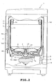
- FIG. 2 is a longitudinal section showing the overall washer.
- An outer cabinet 2 has a generally rectangular shape and a water-receiving tub 3 is elastically supported via four sets of vibration proofing mechanisms 4 (only one set is shown) in the water-receiving tub.
- Each set of vibration proofing mechanism 4 includes a suspension rod 4a having an upper end fixed to an upper portion of the cabinet 2 and the other end to which a vibration damper 4b is mounted.
- the water-receiving tub 3 is elastically supported via the vibration proofing mechanisms 4 such that the vibration produced in the washing operation is prevented from transmitting to the outer cabinet 2.
- a rotating tub 5 serving both as a wash tub and as a dehydration tub is provided in the water-receiving tub 3.
- An agitator (pulsator) 6 is provided on the bottom of the rotating tub 5.
- the rotating tub 5 includes a tub body 5a, an inner cylinder 5b provided inside the tub body 5a and a balance ring 5c provided on upper ends of the tub body and inner cylinder. Upon rotation of the rotating tub 5, a rotational centrifugal force causes water to rise, whereupon the water is discharged through dehydration holes 5d formed in an upper portion of the tub body 5a into the water-receiving tub 3.
- the bottom of the rotating tub 5 has a hole 7 communicating via a drain passage 7a with a drain hole 8.
- a drain valve 9 is provided in a drain passage 10 connected to the drain hole 8. Accordingly, when water is supplied into the rotating tub 5 with the drain valve 9 closed, the water is stored in the rotating tub 5. When the drain valve 9 is opened, the water stored in the rotating tub 5 is discharged through the drain passage 7a, drain hole 8 and drain passage 10.
- the bottom of the water-receiving tub 3 has an auxiliary drain hole 8a connected to a connecting hose (not shown) to bypass the drain valve 9.
- the auxiliary drain hole 8a is further connected to the drain passage 10. Water discharged into the water-receiving tub 3 upon rotation of the tub 5 is further discharged through the auxiliary drain hole 8a.
- a mechanism housing 11 is mounted on the underside of the water-receiving tub 3.
- a hollow tub shaft 12 is rotatably mounted on the mechanism housing 11.
- the rotating tub 5 is connected to the tub shaft 12.
- An agitator shaft 13 is rotatably mounted in the tub shaft 12.
- the agitator 6 is connected to an upper end of the agitator shaft 13.
- the agitator shaft 13 has a lower end connected to a rotor 14a of a brushless DC motor 14 of the outer rotor type.
- the brushless motor 14 directly drives the agitator 6 alternately in opposite directions in a wash step.
- tub shaft 2 and the agitator shaft 13 are coupled by a clutch (not shown) so that the motor 14 directly drives the rotating tub 5 and agitator 6 in one direction. Accordingly, a rotational speed of the motor 14 is approximately equal to a rotational speed of the agitator 6 in the wash step and to rotational speeds of the tub 5 and agitator 6 in the dehydration step.
- FIG. 1 is a block diagram of the control system for the motor 14.
- coordinate ( ⁇ , ⁇ ) represents a rectangular coordinate system obtained by orthogonal conversion of a three-phase coordinate system of three phases of the brushless motor 14 separated from each other by an electrical angle of 120 degrees.
- Coordinate (d, q) represents a coordinate system of a secondary magnetic flux revolved with rotation of the rotor 14a.
- a speed command output 15 supplies a target speed command as a subtracted value to a subtracter 16.
- An estimator 17 detects a detected speed ⁇ of the brushless motor 14. The detected speed ⁇ is supplied as a subtracting value through movable and fixed contacts 50c and 50a of a change-over switch 50 to the subtracter 16.
- a result of the subtraction by the subtracter 16 is supplied to a speed PI (proportional-integral) control 18.
- the speed PI control 18 performs a PI control on the basis of the target speed command and the detected speed ⁇ , thereby generating a quadrature axis (q-axis) current command value I qref and a direct axis (d-axis) current command value I dref . Both current command values I qref and I dref are supplied as subtracted values to subtracters 19 and 20 respectively.
- the motor 14 is driven by a full field control with the d-axis current command value I dref being set at 0.
- An ⁇ /dq converter 21 generates a q-axis current value Iq and a d-axis current value I d , both of which are supplied as subtracting values to the subtracters 19 and 20 respectively. Results of the subtraction by the subtracters 19 and 20 are supplied to current PI controls 22q and 22d respectively.
- a control period in the speed PI control 18 is set at 1 ms.
- the current PI controls 22q and 22d perform a PI control on the basis of a difference between the q-axis and d-axis current command values I qref and I dref , thereby generating a q-axis voltage command value V q and a d-axis voltage command value V d , respectively.
- the q-axis and d-axis voltage command values V q and V d are supplied to a dq/ ⁇ converter 23.
- the estimator 17 detects a rotation phase angle ⁇ of the secondary magnetic flux of the brushless motor 14 (a position angle of the rotor).
- the rotation phase angle ⁇ is supplied to the dq/ ⁇ converter 23, which converts the voltage command values V q and V d to voltage command values V ⁇ and V ⁇ on the basis of the rotation phase angle ⁇ .
- the voltage command values V ⁇ and V ⁇ supplied by the dq/ ⁇ converter 23 are supplied to an ⁇ /UVW converter 24, which converts the voltage command values V ⁇ and V p to three-phase voltage command values V u , V v and V w .
- the three-phase voltage command values are supplied to one fixed contacts 25ua, 25va and 25wa of three change-over switches 25u, 25v and 25w respectively.
- Voltage command values V us , V vs and V ws supplied by a voltage/phase control 26 are supplied to the other fixed contacts 25ub, 25vb and 25wb of the change-over switches 25u, 25v and 25w respectively.
- the change-over switches 25u, 25v and 25w further have movable contacts 25uc, 25vc and 25wc connected to input terminals of a PWM signal forming section 27 respectively.
- the PWM signal forming section 27 modulates a carrier wave of 16 kHz on the basis of the voltage command values V us , V vs and V ws to obtain PWM signals V up (+, -), V vp (+, -) and V wp (+, -) for the respective phases.
- the PWM signals V up (+,-), V vp (+, -) and V wp (+, -) are supplied to an inverter circuit 28.
- each of the PWM signals V up , V vp and V wp has a pulse width corresponding to voltage amplitude based on a sine wave.
- the inverter circuit 28 includes six IGBTs 29a to 29f connected into a three-phase bridge configuration (only one phase is shown in FIG. 1 ) .
- Lower arm side IGBTs 29c and 29d have emitters grounded via current-detecting shunt resistors 30u and 30v respectively and connected via an amplifier-bias circuit (not shown) to an A/D converter 32.
- the amplifier-bias circuit includes an operational amplifier and amplifies a terminal voltage of the shunt resistor 30 and biases the amplified signal so that an output range of the amplified signal falls within the positive side (for example, 0 to +5V).
- An A/D converter 32 performs an A/D conversion of voltage signals appearing on emitters of the IGBTs 29c and 29d, obtaining current data Iu and Iv, which data are supplied to a UVW/ ⁇ converter 33.
- the UVW/ ⁇ converter 33 then supplies the biaxial current data I ⁇ and I ⁇ to an ⁇ /dq converter 21.
- the ⁇ /dq converter 21 supplies the d-axis current value I d and the q-axis current value Iq to the estimator 17 and subtracters 19 and 20.
- the estimator 17 estimates a position angle ⁇ of the rotor 14a and rotational speed ⁇ , supplying them to respective sections.
- the direct current excitation is performed by the initial pattern output section 31 provided in the voltage/phase control 26 so that the rotational position of the rotor 14a is initialized. Thereafter, a starting pattern is applied so that forced commutation is carried out.
- the position angle ⁇ is apparent in the forced commutation and accordingly, estimation is unnecessary.
- the ⁇ /dq converter 21 calculates current values I d and Iq with a position angle ⁇ init serving as an initial value.
- the position angle ⁇ init is obtained from the initial pattern output section 31 immediately before start of the vector control.
- the estimator 17 After start of the vector control, the estimator 17 starts up to estimate the position angle ⁇ and rotational speed ⁇ of the motor rotor 14a. In this case, when the rotor position angle the estimator 17 supplies to the ⁇ /dq converter 21 is ⁇ n , the estimator estimates the rotor position angle ⁇ n , based on the rotor position angle ⁇ n-1 estimated by the vector calculation on the basis of the current values I d and Iq, and the rotor position angle ⁇ n-2 estimated one period before.
- the voltage/phase control 26 includes a speed PI control 34 and a UVW converter 35.
- a subtracter 51 supplies to the speed PI control 34 a result of subtraction between a speed command generated by a speed command output 15 and the estimated speed omega supplied by the estimator 17. Based on the result of subtraction, the speed PI control 34 generates a voltage command (DUTY) and a phase command (PHASE), both of which are supplied to the UVW converter 35.
- a phase angle ⁇ generated by the estimator 17 is supplied to the speed PI control 34 in order that a field weakening control may be performed as will be described later.
- the estimated speed omega is supplied via movable and fixed contacts 50c and 50b of a change-over switch 50 to the subtracter 51.
- the UVW converter 35 converts a command value generated by the speed PI control 34 to three-phase voltage command values U, V and W, which values are supplied to the change-over switch 25. More specifically, the voltage/phase control 26 performs the similar control to that performed by the voltage/phase control system in conventional washing machines.
- the initial pattern output section 31 is provided in the UVW converter 35.
- a change-over control 52 changes over the change-over switches 25 and 50.
- the change-over control 52 controls the change-over of the switches 25 and 50, based on duty information about a PWM signal supplied from the PWM signal forming section 27. Further, the change-over control 52 is designed to supply a command to the voltage/phase control 26 so that a field weakening control is carried out in a high-speed rotation area of the dehydrating operation as will be described later.
- a current control period is set so as to be an inverse of the frequency of PWM carrier wave, 62.5 ⁇ sec.
- FIG. 3 is a flowchart showing the control contents of the microcomputer 36.
- the microcomputer 36 carries out the foregoing start processing (step S1) when a washing operation starts, for example. More specifically, movable contacts 25uc to 25wc of the change-over switches 25u to 25w are changed over to the voltage/phase control 26 (fixed contacts 25ub to 25wb) side by the change-over control 52. Further, the movable contact 50c of the change-over switch 50 is changed over to the fixed contact 50b side.
- the microcomputer 36 then control the initial pattern output section 31 so that the direct current excitation is carried out.
- the rotational position of the rotor 14a is initialized and thereafter, the voltage command values V us to V ws are applied to the inverter circuit 28 so that the forced commutation takes place in the motor 14 (step S2). Consequently, the motor 14 starts rotating and the rotational speed thereof is gradually increased.
- the microcomputer 36 When determining that the motor speed has reached 20 rpm, on the basis of a signal supplied from the initial pattern output section 31 (YES at step S3), the microcomputer 36 changes over the change-over switches 25u to 25w so that the movable contacts 25uc to 25wc are connected to the fixed contacts 25ua to 25wa respectively. The microcomputer 36 further changes over the movable contact 50c of the change-over switch 50 to the fixed contact 50a side. The microcomputer 36 then starts supplying the target speed command, thus performing the voltage/phase control (PI control) (step S4). In other words, it is difficult to perform the vector control with high precision in a low speed range.
- PI control voltage/phase control
- the microcomputer 36 then refers to the rotational speed w supplied from the estimator 26 to determine whether the motor speed has reached 60 rpm (step S5). When determining that the motor speed has reached 60 rpm (YES at step S5), the microcomputer 36 starts the vector control (and the speed PI control) (step S6). Thereafter, the microcomputer 36 continues the operation of the washing machine until receiving the instruction of operation stop (step S7). When a washing or rinsing operation is to be carried out in this while, the motor 14 is rotated in normal and reverse directions so that a maximum speed reaches 150 rpm.
- the PWM signal forming section 27 includes an internal up-down counter (not shown) generating a PWM carrier wave of 16 kHz. When a count value of the up-down counter has reached "0" or a trough of a triangular wave, the PWM signal forming section 27 supplies a conversion timing signal to the A/D converter 32. See FIG. 5A .
- the PWM signal forming section 27 compares the levels of the voltage command values V u to V w supplied by the ⁇ /UVW converter 24 with the level of the PWM carrier wave, as shown in FIGS. 5B and 5C .
- the PWM signal forming section 27 supplies the PWM signals V up (+) , V vp (+) and V wp (+) so that the IGBTs 29a to 29c of the upper arm side are turned on in a period when the level of the PWM carrier wave is higher than those of the voltage command values V u to V w .
- the IGBTs 29d to 29f of the lower arm side are turned on with a dead time between ON and OFF periods in a period when the IGBTs 29a to 29c of the upper arm side are turned off.
- FIGS. 6A to 6C are waveform charts showing the relationship among inversion IMINV of motor phase current, current ISR flowing into the shunt resistor 30 and phase voltage.
- the IGBT 29 of the lower arm side is turned on so that the phase voltage is at 0 V in a period when the current ISR flows. Accordingly, the trough of the triangular wave shows an intermediate phase of the period when the IGBTs 29d to 29f are turned on.
- the phase current flowing into the lower arm side of the inverter circuit 28 can reliably be sampled when the A/D converter 32 performs the A/D conversion at the time when the count value of the PWM signal forming section 27 is 0.
- the two-phase current values I u and I v converted by the A/D converter 32 are supplied through the UVW/ ⁇ and ⁇ /dq converters 33 and 21 together with the estimated current value I w to be converted to biaxial current data I ⁇ and I p and further to biaxial current data I d and Iq.
- the biaxial current data are supplied to the estimator 17 and the subtracters 19 and 20 so that the position angle ⁇ and the rotational speed ⁇ are estimated by the estimator.
- the current Iq flows in a direction perpendicular to the direction of the secondary magnetic flux of the motor 14 and serves for torque development.
- the current I d flows in a direction in parallel with the direction of the secondary magnetic flux and does not serve for torque development.
- the speed PI control 18 supplies q-axis and d-axis current command values I qref and I dref on the basis of the difference between the target speed command and the detected speed ⁇ .
- the current PI controls 22q and 22d supply voltage command values V q and V d on the basis of the differences between the command values I qref and I dref and the detected current values I q and I d respectively.
- the dq/ ⁇ converter 23 and ⁇ /UVW converter 21 convert the voltage command values V q and V d to voltage command values V u , V v and V w , the latter being delivered to the PWM signal forming section 27.
- the PWM signal forming section 27 supplies PWM signals V up , V vp and V wp to the inverter circuit 28. As a result, the motor phase windings are energized.
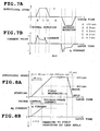
- FIG. 7A shows a rotational speed control pattern for the agitator 6 (motor 14) in the washing or rinsing operation.
- the rotational speed is increased from 0 rpm to 150 rpm in 0.3 sec. and then maintained at 150 rpm for 0.5 sec. Continuously, the rotational speed is decreased from 150 rpm to 0 rpm in 0.3 sec. Subsequently, the rotational direction is revered after an interrupt period of 0.7 sec.
- FIG. 7B shows an output pattern of a q-axis current command value Iq ref the speed PI control 18 supplies according to the rotational speed control pattern as shown in FIG. 7A .
- a d-axis current command value Id ref is set at "0" and the motor 14 is driven in a full field state.
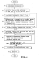
- FIG. 4 is a flowchart showing the control contents for the motor 14 in the dehydrating operation.
- the start processing of step A1 in FIG. 4 corresponds to steps S1 to S5 in FIG. 3 .
- the change-over control 52 changes over the change-over switches 50 and 25 to the vector control side (that is, the fixed contacts 50a and 25a side) (step A2).
- FIGS. 8A and 8B are views similar to FIGS. 7A and 7B in the dehydrating operation, respectively.
- the rotational speed is increased from 0 rpm to 900 rpm in 90 sec. and then maintained at 900 rpm for 4 minutes in the dehydration as shown in FIG. 8A .
- the rotational speed is then decreased from 900 rpm to 0 rpm in 15 sec.
- the target rotational speed is gradually increased toward 900 rpm (steps A3 and A4) .
- the q-axis current command value Iq ref is supplied to the motor 14 so that the torque is increased, in the same manner as in the washing or rinsing operation, as shown in FIG. 8B .
- the d-axis current command value Id ref is set at "0" and the motor 14 is driven in the full field state.
- the change-over control 52 then refers to information about duty of a PWM signal supplied from the PWM signal forming section 27 thereby to determine whether the timing has come to change over the vector control to the voltage/phase control (step A5) .
- the change-over timing depends upon whether the duty of PWM signal has exceeded 90%.
- the microcomputer returns to step A2.
- the microcomputer changes over the change-over switches 50 and 25 to the voltage/phase control (fixed contacts 50b and 25b side) (step A6) so that the voltage/phase control (PI control) is carried out by the speed PI control 34.
- the duty of the PWM signal reaches 90% when the rotational speed of the motor 14 is increased to about 400 rpm.
- the change-over control 52 supplies a change-over signal also to the speed PI control 34 for execution of the weakening field control, the target speed of the motor 14 (speed command value) is further increased (step A7).
- the field weakening control is carried out by means of lead angle energization.
- FIGS. 9H to 9J show an energization timing (full field) providing a maximum efficiency of the motor 14 relative to phases P0 to P5 for every 60 degrees estimated by the estimator 17.
- the energization timing is shifted to the lead phase side by a phase command PHASE so that the field is weakened while voltage applied to the motor 14 is maintained at the level based on a voltage command (DUTY) supplied by the speed PI control 34 as shown in FIGS. 9K to 9M.
- FIGS. 9A to 9G show a positional relation between the stator winding and the rotor magnet in a case where the motor is rotated.
- the energization angle is set so as to be increased according to an increase in the speed command value ⁇ ref , whereby induced voltage induced in the motor 14 is restrained.
- step A8 the change-over control 52 determines whether the rotational speed of the motor 14 has reached 900 rpm.
- the change-over control 52 returns to step A7 when determining that the rotational speed has not reached 900 rpm (NO).
- the change-over control 52 carries out the dehydrating operation for a predetermined period of time (four minutes, in this case) (step A9).
- the change-over control 52 stops energization to the motor 14 and operates a braking mechanism (not shown) to stop the rotor thereby to stop the rotating tub 5 (step A10), completing the processing.
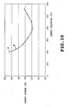
- FIG. 10 shows the relationship between voltage (V) applied to the motor 14 and input power (W) in a case where the dehydrating operation is carried out at maximum speed of 900 rpm.
- Point A in FIG. 10 indicates a case where the field weakening control is carried out simultaneously with the vector control. In this case, applied voltage is 200 V and input power is about 208 W.
- point B indicates a case where the field weakening control is carried out simultaneously with the voltage/phase control. In this case, applied voltage rises to about 220 V and input power drops to about 185 W. More specifically, the applied voltage can be raised when the control manner in the high-speed rotation area is changed over from the vector control to the voltage/phase control, the input power can be reduced about 10%.
- the motor 14 is operated in the full field mode in the washing, rinsing and low-speed rotation area of the dehydrating operation.
- the motor 14 is operated in the field weakening mode in the high-speed rotation area of the dehydrating operation.
- the vector control is carried out for the output torque of the motor 14 when the full field operation is executed, whereas the voltage/phase control is carried out for the motor 14 when the field weakening operation is executed. Accordingly, the field weakening operation can be performed while the voltage applied to the motor 14 is set at a higher value in the high speed rotation area in execution of the dehydrating operation. Consequently, the consumed power can be reduced and accordingly, the efficiency can be improved.
- the field weakening operation can be carried out while the voltage supplied to the motor 14 is set at a high value.
- FIGS. 11 to 16 illustrate a second embodiment in which the invention is applied to a full automatic washer-drier.
- Identical or similar parts in the second embodiment are labeled by the same reference symbols as those in the first embodiment and the description of these parts will be eliminated. Only the differences will be described in the following.
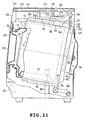
- FIG. 11 is a longitudinally sectional side view of the drum washer-drier.
- a door 62 is mounted on a central front of an outer cabinet 61 serving as an outer shell of the drum washer-drier.
- An operation panel 63 and a detergent supply case (not shown) are provided in an upper part of the front of the outer cabinet 61.
- a laundry access opening 65 formed in the central part of the front of the outer cabinet 61 is closed and opened by the door 62.
- An operating circuit unit 66 is provided on an upper part of the front inside of the outer cabinet 61 (the inside of the operation panel 63).
- An operation circuit unit 67 is provided on a lower part of the front inside of the outer cabinet 61.
- a water tub 68 is provided in the outer cabinet 61.
- the water tub 68 is formed into a cylindrical shape and its axis extends back-and-forth (right-and-left in FIG. 11 ).
- the water tub 68 is inclined frontwardly upward.
- the water tub 68 is supported by a pair of right and left elastic support devices 69.
- a drum (dehydrating tub) 70 is provided in the water tub 68 so as to be coaxial with the latter.
- the drum 70 functions as a tub commonly used for washing, dehydration and drying.
- the drum 70 has a number of small holes 71 formed substantially in an overall area of a drum part (only a part of small holes are shown in FIG. 11 ).
- An inner circumferential face of the drum part has a plurality of baffles 72 (only one of the baffles is shown in FIG. 11 ). Upon rotation of the drum 70, the baffles 72 scrape laundry therein.
- the water tub 68 and drum 70 have access openings 73 and 74 formed in the fronts so that laundry is put into and taken out of the drum through the access openings, respectively.
- the access opening 73 of the water tub 68 communicates through bellows 75 with the access opening 65 of the outer cabinet 61 (in a watertight manner).
- the opening 74 of the drum 70 confronts the opening 73 of the water tub 68 so that the access opening 65 communicates with the interior of the drum 70.
- An electric motor 76 for driving the drum 70 is provided on a rear of the water tub 68.
- the motor 76 comprises a brushless DC motor of the outer rotor type as the motor 14.
- a stator 76a is mounted on the rear of the water tub 68.
- a rotating shaft 76c is disposed at the center of a rotor 76b and extends into the water tub 68.
- the rotating shaft 76c has a front end on which the central rear of the drum 70 is mounted.
- a water reservoir 77 is mounted on the underside of the water tub 68.
- a heater 78 for heating wash water is provided in the water reservoir 77.
- a drain hose 80 is connected via a drain valve 79 to a rear of the water reservoir 77.
- the drain valve 79 is an electrically driven type and is opened by an electromagnet, motor or the like.
- a blower 81 is provided on the upper rear of the water tub 68 and a heater 82 is provided on the upper front of the water tub 68.
- the blower 81 includes a blowing blade 84 provided in a casing 83, an electric motor 85 (see FIG. 12 ) driving the blowing blade 84 and provided outside the casing 83 and a belt transmission mechanism (not shown) provided between the blowing blade 84 and the motor 85.
- the heater 82 includes a hot air producing heater 88 provided in the casing 87.
- the casing 87 has an entrance communicating with an exit of the casing 83 of the blower 81.
- a duct 89 is provided on the upper front of the water tub 68 and has one end communicating with an exit of the casing 87 of the heater 82 and the other end confronting the water tub 68.
- a heat exchanger 90 is provided on the rear of' the water tub 68.
- the heat exchanger 90 is of the water cooling type in which water is poured from an upper part so that heat exchange occurs between the poured water and water content of air flowing from the lower interior, whereby air is cooled and then evaporated thereby to be dehumidified.
- the heat exchanger 90 is generally hollow and curved concentrically with the rotating shaft 76c of the motor 76 serving as rotation center of the drum 70. Thus, the heat exchanger 90 is disposed so as to keep away from the motor 76.
- the heat exchanger 90 has an air inlet 91 which is formed in its lower part and also serves as a water outlet.
- the air inlet 91 communicates with the lower interior of the water tub 68.
- the heat exchanger 90 has an upper part which communicates through a duct 92 with the casing 83 of the blower 81.
- a drying unit 93 includes the heat exchanger 90, duct 92, blower 81, heater 82 and duct 89.
- a water pipe 94 extends across the upper interior of the heat exchanger 90.
- the water pipe 94 has a row of spouts (not shown) formed in the underside thereof confronting a lower part of the heat exchanger 90.
- the water pipe 94 has an end located outside the heater exchanger 90.
- the end of the water pipe 94 is connected to one end of a water tube 95, whereas the other end of the water tube 95 is connected to a water-supply valve 96 provided in the uppermost interior of the outer cabinet 61.
- a water level sensor 97 is provided in the uppermost interior of the outer cabinet 61 (see FIG. 12 ).
- the water level sensor 97 detects a water level in the water tub 68 on the basis of air pressure transferred from an air trap (not shown) via an air tube.
- the water tub 68 communicates via the small holes 71 with the drum 70, whereupon water is reserved in the drum 70 through the small holes 71 when the water is reserved in the water tub 68. Accordingly, the water level sensor 97 and the air trap and air tube also detect the water level in the drum 70.
- a water supply pump 99 is provided in the uppermost interior of the outer cabinet 61.
- the water supply pump 99 sucks water other than from the water supply system, such as bathwater, via a suction hose and discharges the water.
- a water case 100 is provided in the uppermost front of the interior of the outer cabinet 61.
- the water case 100 receives the water discharged from the water supply pump 99 via a connecting hose 101.
- the water case 100 also receives water supplied a faucet and a water supply valve 102 (see FIG. 12 ) from the water supply system (not shown) via a connecting hose 103.
- the aforesaid detergent case is enclosed in the water case 100, and the front bottom of the water case 100 communicates via the water pipe 94 into the water tub 68.
- the water supply valves 102 and 96 and drain valve 79 are of the motor-operated type.
- FIG. 12 shows an electrical arrangement comprising a microcomputer 105 (control means) and the periphery thereof.
- the microcomputer 105 is contained in the control circuit unit 67 and controls an overall operation of the drum washer-drier.
- Various operation signals are supplied to the microcomputer 1 from an operation input section 106 including various switches on the operation panel 63.
- the operation input section 106 is contained in the operation circuit unit 66 and supplies various operation signals according to the operation made by the user on the operation panel 63.
- a water level signal is supplied from the water level sensor 97 to the microcomputer 105 and a soil signal is supplied to the microcomputer 105 from a soil sensor 107 provided for detecting soil of washing liquid in the water tub 68. Further, a temperature sensor 108 (thermistor) detecting a temperature in the drum 70 supplies a temperature signal to the microcomputer 105. A water temperature sensor 112 detects a temperature of the water in the water tub 68 and supplies a water temperature signal to the microcomputer 105.
- the microcomputer 105 Based on a current signal supplied to an A/D converter 32 and a previously stored control program, the microcomputer 105 supplies a drive control signal to an inverter circuit 109 driving the motor 76.
- the arrangement in which the microcomputer 105 controls the inverter circuit 109 and further accordingly the motor is the same as that as shown in FIG. 1 in the first embodiment.
- the microcomputer 105 supplies drive control signals to a drive circuit 111 for driving a display unit 110 comprising display sections of the operation panel 63, a hot water heater 78 for heating wash liquid, drain valve 79, blowing motor 85 for the blower 81, hot air heater 88, water supply pump 99 and water supply valves 96 and 102.
- FIG. 13 shows a sequence of steps of the washer-drier.
- laundry amount detection is carried out in order that an amount of laundry the user has put into the drum 70 may be estimated.
- an amount of detergent to be dispensed is displayed on the display unit 60.
- the user puts the detergent into the detergent case.
- the drum 70 is rotated by the motor 76 repeatedly alternately in the normal and reverse directions.
- the heater 78 is energized when WARM-WATER WASHING is selected by the user.
- the control sequence When DRAIN and DEHYDRATION are executed at a final stage of the wash step, the control sequence subsequently advances to a rinse step.
- RINSE 1 starts after WATER SUPPLY has been carried out. After RINSE 1, a set of DRAIN, DEHYDRATION, DRAIN and RINSE is repeated twice. Thus, RINSE is executed three times.
- the control sequence then advances to a dehydration step in which DRAIN and DEHYDRATION are carried out. Thereafter, the control sequence advances to a drying step in which the drum 70 is rotated and the heater 88 is energized. The motor 85 is rotated so that hot air is circulated in the drum 70.
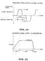
- FIGS. 14 to 16 show control patterns for the rotational speed of the drum 70 (or motor 76) in the wash or rinse, dehydration and drying.
- the rotational speed is increased from 0 rpm to 50 rpm in one second and maintained at 50 rpm for 3 seconds.
- the rotational speed is then decreased from 50 rpm to 0 rpm in one second.
- the direction of rotation is reversed after 3-second's stop.
- This pattern is repeatedly carried out.
- the output torque of the motor 76 is controlled on the basis of the q-axis current command value Iq ref by the vector control.
- the rotational speed is controlled by the PI control in which the full field control is executed with d-axis current command value Id ref being set at 0.
- the rotational speed is increased from 0 rpm to 1000 rpm in 3 minutes and maintained at 1000 rpm for 7 minutes.
- the rotational speed is then decreased from 1000 rpm to 0 rpm in one minute.
- the control is carried out in accordance with the flowchart of FIG. 4 in the same manner as in the first embodiment.
- the duty of the PWM signal exceeds 90% (for example, 500 rpm)
- the control manner is changed from the vector control to the voltage/phase control, and the field weakening control is carried out by way of the lead angle energization as shown in FIG. 9 .
- the rotational speed is increased to 60 rpm and maintained at 60 rpm.
- the rotational speed is continuously decreased from 60 rpm to 0 rpm. It takes one minute to increase and decrease the rotational speed in the above-described manner.
- the direction of rotation is reversed after a slight stop period. This pattern is repeated.
- torque is controlled by the vector control and the rotational speed is controlled by the PI control in the same manner as in the washing or rinsing operation.
- the field weakening control is carried out.
- the motor 76 is operated under the full field control in the washing and rinsing operations and low-speed rotation area of the dehydrating operation, whereas the motor 76 is operated under the field weakening control in the high-speed rotation area of the dehydrating operation.
- the vector control is carried out for the control of the output torque of the motor 76 when the full field operation is executed.
- the voltage/phase control is carried out for the motor 76 when the field weakening operation is executed. Accordingly, the same effect can be achieved in the washer-drier as in the first embodiment.
- FIGS. 17 to 20 illustrate a third embodiment in which the invention is applied to a washer-drier of the vertical axis type.
- FIG. 17 is a longitudinal section of the washer-drier.
- a lid 122 is provided for opening and closing the access opening through which laundry is put into and taken out of the rotating tub.
- the lid 122 is mounted on the central top of the body 121 constituting the outer shell.
- An operation panel 123 having various selecting switches is provided in the front of the body 121.
- a control device 124 controls the overall washing and drying operations and comprises a microcomputer-based circuit.
- the control device 124 is provided inside the body 121 so as to correspond to the operation panel 123.
- a water tub 125 has an upper opening and is formed into the shape of a bottomed cylinder and can reserve water.
- the water tub 125 is mounted on a plurality of elastic supporting devices 126 (only one being shown) in the body 121.
- a drain hole 125a is located at a lowermost portion of the water tub 125.
- a drain valve 127 is connected to the drain hole 125a.
- a drain hose 128 having one end side extending outside the machine is connected to the drain hole 125a.
- the aforesaid water tub 125 is made from a synthetic resin, for example, a composite material comprising polypropylene as a base material and 15 wt % glass fiber.
- a heat resisting reinforcement is applied to the water tub 125 so that the water tub can be used as a drying chamber.
- a rotating tub 129 accommodates laundry and serves both as a washing tub and as a dehydrating tub.
- the rotating tub 129 is rotatably provided in the water tub 125.
- the rotating tub 129 is made from a metal or a metal-based material so as to be strong.
- the rotating tub 129 has an upper opening substantially in the same manner as the water tub 125 and a number of small holes 129a formed in an overall peripheral wall including the bottom, whereupon the rotating tub 129 is formed into a vertically cylindrical shape.
- An agitator 130 is rotatably mounted on the central bottom of the rotating tub 129.
- a balance ring 129b is secured to an upper end of the rotating tub 129.
- the rotating tub 129 and the agitator 130 are driven by a drive motor 131 mounted on the underside of the water tub 125.
- a drive motor 131 mounted on the underside of the water tub 125.
- the agitator 130 is driven via a clutch mechanism (not shown), whereas both agitator 130 and water tub 125 are driven in the dehydrating or drying operation.
- the water tub 125 is controlled so as to be rotated at a lower speed in the drying operation than in the dehydrating operation.
- the motor 131 comprises a brushless motor of the outer rotor type as in the first or second embodiment.
- a warm air circulating passage 132 supplies warm air into the water tub 125 and is formed so as to extend from the lower end to the upper end of the water tub 125 at an inner corner of the body 121 and at one side of the water tub 125.
- the warm air circulating passage 132 has a lower end communicating through a duct 133a with the drain hole 125a formed in a lower portion of the water tub 125.
- the warm air circulating passage 132 has an upper end which is open so as to face the top opening of the water tub 125.
- a dehumidifying unit 134 is formed between the ducts 133a and 133b.
- a warm air generator comprises a blower 135 and a drying heater 136 both provided downstream from the dehumidifying unit 134.
- the warm air circulating passage 132 is formed by the duct 133, the dehumidifying unit 134, the warm air generator and a part of the water tub 125.
- a heat exchanger 137 constituting the dehumidifying unit 134 is formed into the shape of a tube having bellows.
- the heat exchanger 137 is connected to the ducts 133a and 133b.
- a cooling fan 138 supplies outside air as cooling air to the peripheral side of the heat exchanger 137.
- a short cylindrical duct 139 surrounds an upper portion of the heat exchanger 137 so as to form an air passage guiding the cooling air downward.
- Air (discharged warm air) flowing upward along the interior of the heat exchanger 137 as shown by arrow in FIG. 17 is cooled such that condensed water content drops, whereby air is dehumidified.
- the above-described mechanism constitutes an air-cooled dehumidifier 140.
- Water supply means for pouring the cooling water is provided in the upper interior of the heat exchanger 137.
- the water supply means comprises a water-supply switching valve 141 connected to a water supply source such as water supply system, water passages 142 and 143 at least bifurcated from the switching valve 141.
- the water passage 142 communicates with the upper interior of the heat exchanger 137, and a small amount of cooling water is caused to flow along the water passage 142.
- the water passage 143 faces the interior of the water tub 125, and a large amount of water is supplied along the water passage 143. Accordingly, a small amount of cooling water is supplied from the water passage 142 into the heat exchanger 137.
- the water is brought into contact with air flowing upward in the heat exchanger 137, thereby cooling the air. As a result, the water content contained in the air is condensed such that the air is dehumidified.
- the water supply means for supplying cooling water is provided in the heat exchanger 137, whereby a water-cooled dehumidifier 144 is constituted.
- the dehumidifying unit 134 thus have air-cooled and water-cooled dehumidifying means.
- the heat exchanger 137 in the embodiment is formed into the shape of bellows, a heat-exchange area is increased such that efficient heat exchange can be carried out.
- An agitating rib 145 protrudes from the lower interior of the heat exchanger 137. Air flowing through the heat exchanger 137 is uniformly brought into contact with the cooling water by the agitating rib 145. Further, since the cooling water is dispersed by the agitating rib 145, the contact between water and air can be rendered further desirable.
- Dry air dehumidified by the dehumidifying unit 134 is efficiently changed into warm air by the blower 135 and heater 136 provided downstream for producing warm air.
- the warm air is supplied through the duct 133b into the water tub 125.
- the dehumidifying unit 134 and the warm air circulating passage 132 are fixed to the elastically supported water tub 125 side although detailed mounting structure is eliminated. Further, the cooling fan 138 introducing outside air is also elastically supported at the position where the fan faces the exterior of the body 121. Further, the electrical arrangement of the washer-drier is basically the same as that in the second embodiment.
- FIGS. 18 to 20B show rotational speed control patterns for the motor 131 in the wash or rinse, dehydration and drying.
- the rotational speed is increased from 0 rpm to 150 rpm in 0.3 sec. and maintained at 150 rpm for 0.5 sec.
- the rotational speed is then decreased from 150 rpm to 0 rpm in 0.5 sec.
- the direction of rotation is reversed after a stop period of 0.7 sec. This pattern is repeated.
- the vector control is carried out by the q-axis current command value Iq ref regarding the output torque of the motor 76 in the same manner as in the first embodiment.
- the PI control is carried out, and the full field control is executed with the d-axis current command and value Id ref being set at 0.
- the rotational speed is increased from 0 rpm to 900 rpm in 3 min. and maintained at 900 rpm for 7 min. The rotational speed is then decreased from 900 rpm to 0 rpm in 1 min.
- control is executed in accordance with the flowchart of FIG. 4 in the same manner as in the first embodiment.
- the duty of the PWM signal exceeds 90% (rotational speed of 400 rpm)
- the control manner is switched from the vector control to the voltage/phase control, and the field weakening control is executed.
- the rotational speed is increased to 50 rpm and maintained at 50 rpm. Subsequently, the rotational speed is decreased from 50 rpm to 0 rpm. It takes 10 minute to increase and decrease the rotational speed in the above-described manner.
- the direction of rotation is reversed after a one-minute stop period (see FIG. 20A ). Further, the agitator 130 is driven alternately in the normal and reverse directions at 100 rpm (see FIG. 20B ). This pattern is repeated. In this case, torque is controlled by the vector control and the rotational speed is controlled by the PI control in the same manner as in the washing or rinsing operation. The full field control is carried out.
- the same effect can be achieved from the third embodiment as from the first or second embodiment even when the invention is applied to the washer-drier of the vertical axis type.
- the rotational speeds and current values are examples and these values may suitably be changed according to design.
- the control mode is changed from the vector control to the voltage/phase control in the high speed area of the dehydrating operation.
- the timing for the change should not be limited to duty 90% of the PWM signal. A most suitable criterion may be set according to the design.
- the inverter device of the present invention when applied to a washer or washer-drier, reduces electrical power consumption and accordingly improve the motor efficiency.
Landscapes
- Engineering & Computer Science (AREA)
- Textile Engineering (AREA)
- Power Engineering (AREA)
- Control Of Washing Machine And Dryer (AREA)
- Main Body Construction Of Washing Machines And Laundry Dryers (AREA)
- Control Of Ac Motors In General (AREA)
- Control Of Motors That Do Not Use Commutators (AREA)
Description
- The present invention relates to an inverter for a washer controlling an electric motor imparting a rotational driving force required for washing, rinsing and dehydrating operations with respect to an automatic washing machine in which steps of wash, rinse and dehydration are consecutively carried out, and an inverter for a washer-drier controlling an electric motor imparting a rotational driving force required for washing, rinsing and dehydrating operations with respect to an automatic washing machine in which steps of wash, rinse and dehydration are consecutively carried out.
- In automatic washing machines, DC brushless motors have conventionally been used as motors for rotating a mixing blade (pulsator) or a rotating tub when washing, rinsing and dehydrating operations are carried out. A system for driving the DC brushless motors by an inverter circuit has been employed widely. Voltage applied to the motor is increased or decreased when torque is controlled according to driving conditions of the motor. However, output torque controlled by the applied voltage is not proportional to voltage although a rotational speed of the motor is proportional to the output torque. As a result, a difference tends to be caused between a target speed command and a detected motor speed, whereupon the control tends to become unstable.
- In view of the foregoing problem, the inventors proposed in
EP 1 265 351 - Motors used in the washers or washer-driers are controlled so as to be rotated at low speeds in the washing operation and so as to be rotated at high speeds in the dehydrating operation. Since induced voltage caused in a motor winding is raised during high speed rotation, drive voltage to be supplied also needs to be raised with rise of the induced voltage. Generally, however, the drive voltage which can be supplied has a definite limit when an electric motor is controlled by an inverter. Accordingly, a field weakening operation is carried out in the high speed rotation so that the number of revolution of the motor is increased while the induced voltage of the motor is restrained.
- In the vector control technique proposed by
EP 1 265 351 - More specifically, output voltage of an inverter circuit cannot be set to be approximately 100% when the field weakening operation is carried out. Accordingly, since the magnetic field needs to be weakened more as the voltage drops, the motor efficiency is reduced and the power supply current is inevitably increased. As a result, the inverter and motor become large-scale.
- The present invention was made in view of the foregoing and an object thereof is to provide an inverter which can raise the output voltage in the case of the field weakening operation even when the vector control is introduced to the control of the motor used in the washer or washer-drier.
- The present invention provides an inverter for a washer comprising a control unit controllinga brushless DC motor supplying a rotational driving force for performance of washing, rinsing and dehydrating operations with respect to a full automatic washer in which steps of wash, rinse and dehydration are consecutively carried out, wherein the control unit controls the motor so that the motor is operated with a full field in the washing and rinsing operations in a low-speed rotation region and so that the motor is operated with a weak field in a high speed rotation region of the dehydrating operation, and in that the control unit controls an output torque of the motor in a vector control based on a current command generated according to a difference between a speed command and a detected speed of the motor when the full field operation is carried out and the control unit controls the motor in a voltage and phase control based on a voltage command and a phase command both generated according to the difference between the speed command and the detected speed of the motor when the field weakening operation is carried out.
- In short, in the high speed rotation region in which the field weakening operation needs to be performed, the control unit switches the control manner to the voltage and phase control without execution of the vector control. Accordingly, the output voltage of the inverter circuit does not exceed the voltage given as a command value. Consequently, the field weakening operation can be performed when the voltage supplied to the motor is set higher in the high speed rotation region of the dehydrating operation.
-
-
FIG. 1 is a block diagram of the control system mainly comprising a microcomputer, showing a first embodiment in which the invention is applied to a washer; -
FIG. 2 is a longitudinal section of the washing machine; -
FIG. 3 is a flowchart showing control contents at an initial stage of the motor control by the microcomputer; -
FIG. 4 is a view similar toFIG. 3 , showing the case of the dehydrating operation; -
FIGS. 5A to 5C show waveforms of PWM carrier wave and upper and lower arm side gate signals respectively; -
FIGS. 6A to 6C are waveform charts showing the relationship among inversion IMINV of motor phase current, current ISR flowing into a shunt resistance and phase current; -
FIGS. 7A and 7B show rotational speed control pattern for the agitator (motor) in the washing or rinsing operation and output pattern of q-axis current command value Iqref delivered by a speed PI control section according to the rotational speed control pattern, respectively; -
FIGS. 8A and 8B are views similar toFIGS. 7A and 7B , showing the case of the dehydrating operation, respectively; -
FIGS. 9A to 9M explain the weak field control by lead angle, 9A to 9G showing the positional relationship between the stator winding and rotor magnet, 9H to 9J showing the full field control and 9K to 9M showing the weak field control; -
FIG. 10 shows the relationship between voltage (V) applied to the motor and input power (W) when the motor is driven at the maximum rotational speed in the dehydrating operation; -
FIG. 11 is a longitudinal section of the drum washer-drier in accordance with second embodiment of the invention; -
FIG. 12 is a block diagram showing electrical arrangement of the microcomputer and its peripheral components; -
FIG. 13 shows sequential steps of the washer-drier; -
FIG. 14 shows motor rotational speed control pattern in the washing or rinsing operation; -
FIG. 15 is a view similar toFIG. 14 , showing the case of the dehydrating operation; -
FIG. 16 is a view similar toFIG. 14 , showing the case of the drying operation; -
FIG. 17 is a view similar toFIG. 2 , showing a third embodiment where the - invention is applied to a vertical axis type washer-drier;
-
FIG. 18 is a view similar toFIG. 14 ; -
FIG. 19 is a view similar toFIG. 15 ; and -
FIG. 20A is a view similar toFIG. 16 andFIG. 20B is a view showing the rotation direction of the pulsator in a drying operation. - A first embodiment in which the present invention is applied to a vertical axis type full automatic washing machine will be described with reference to
FIGS. 1 to 10 . Firstly,FIG. 2 is a longitudinal section showing the overall washer. Anouter cabinet 2 has a generally rectangular shape and a water-receivingtub 3 is elastically supported via four sets of vibration proofing mechanisms 4 (only one set is shown) in the water-receiving tub. Each set ofvibration proofing mechanism 4 includes asuspension rod 4a having an upper end fixed to an upper portion of thecabinet 2 and the other end to which avibration damper 4b is mounted. The water-receivingtub 3 is elastically supported via thevibration proofing mechanisms 4 such that the vibration produced in the washing operation is prevented from transmitting to theouter cabinet 2. - A rotating
tub 5 serving both as a wash tub and as a dehydration tub is provided in the water-receivingtub 3. An agitator (pulsator) 6 is provided on the bottom of the rotatingtub 5. The rotatingtub 5 includes a tub body 5a, aninner cylinder 5b provided inside the tub body 5a and abalance ring 5c provided on upper ends of the tub body and inner cylinder. Upon rotation of therotating tub 5, a rotational centrifugal force causes water to rise, whereupon the water is discharged throughdehydration holes 5d formed in an upper portion of the tub body 5a into the water-receivingtub 3. - The bottom of the
rotating tub 5 has ahole 7 communicating via a drain passage 7a with adrain hole 8. Adrain valve 9 is provided in adrain passage 10 connected to thedrain hole 8. Accordingly, when water is supplied into therotating tub 5 with thedrain valve 9 closed, the water is stored in therotating tub 5. When thedrain valve 9 is opened, the water stored in therotating tub 5 is discharged through the drain passage 7a,drain hole 8 and drainpassage 10. - The bottom of the water-receiving
tub 3 has anauxiliary drain hole 8a connected to a connecting hose (not shown) to bypass thedrain valve 9. Theauxiliary drain hole 8a is further connected to thedrain passage 10. Water discharged into the water-receivingtub 3 upon rotation of thetub 5 is further discharged through theauxiliary drain hole 8a. - A
mechanism housing 11 is mounted on the underside of the water-receivingtub 3. Ahollow tub shaft 12 is rotatably mounted on themechanism housing 11. Therotating tub 5 is connected to thetub shaft 12. Anagitator shaft 13 is rotatably mounted in thetub shaft 12. Theagitator 6 is connected to an upper end of theagitator shaft 13. Theagitator shaft 13 has a lower end connected to arotor 14a of abrushless DC motor 14 of the outer rotor type. Thebrushless motor 14 directly drives theagitator 6 alternately in opposite directions in a wash step. - Further, the
tub shaft 2 and theagitator shaft 13 are coupled by a clutch (not shown) so that themotor 14 directly drives therotating tub 5 andagitator 6 in one direction. Accordingly, a rotational speed of themotor 14 is approximately equal to a rotational speed of theagitator 6 in the wash step and to rotational speeds of thetub 5 andagitator 6 in the dehydration step. -
FIG. 1 is a block diagram of the control system for themotor 14. InFIG. 1 , coordinate (α, β) represents a rectangular coordinate system obtained by orthogonal conversion of a three-phase coordinate system of three phases of thebrushless motor 14 separated from each other by an electrical angle of 120 degrees. Coordinate (d, q) represents a coordinate system of a secondary magnetic flux revolved with rotation of therotor 14a. - A
speed command output 15 supplies a target speed command as a subtracted value to asubtracter 16. Anestimator 17 detects a detected speed ω of thebrushless motor 14. The detected speed ω is supplied as a subtracting value through movable and fixed contacts 50c and 50a of a change-over switch 50 to thesubtracter 16. A result of the subtraction by thesubtracter 16 is supplied to a speed PI (proportional-integral)control 18. - The
speed PI control 18 performs a PI control on the basis of the target speed command and the detected speed ω, thereby generating a quadrature axis (q-axis) current command value Iqref and a direct axis (d-axis) current command value Idref. Both current command values Iqref and Idref are supplied as subtracted values to subtracters 19 and 20 respectively. When a vector control is carried out, themotor 14 is driven by a full field control with the d-axis current command value Idref being set at 0. An αβ/dq converter 21 generates a q-axis current value Iq and a d-axis current value Id, both of which are supplied as subtracting values to thesubtracters speed PI control 18 is set at 1 ms. - The current PI controls 22q and 22d perform a PI control on the basis of a difference between the q-axis and d-axis current command values Iqref and Idref, thereby generating a q-axis voltage command value Vq and a d-axis voltage command value Vd, respectively. The q-axis and d-axis voltage command values Vq and Vd are supplied to a dq/
αβ converter 23. Theestimator 17 detects a rotation phase angle θ of the secondary magnetic flux of the brushless motor 14 (a position angle of the rotor). The rotation phase angle θ is supplied to the dq/αβ converter 23, which converts the voltage command values Vq and Vd to voltage command values Vα and Vβ on the basis of the rotation phase angle θ. - The voltage command values Vα and Vβ supplied by the dq/
αβ converter 23 are supplied to an αβ/UVW converter 24, which converts the voltage command values Vα and Vp to three-phase voltage command values Vu, Vv and Vw. The three-phase voltage command values are supplied to one fixed contacts 25ua, 25va and 25wa of three change-over switches 25u, 25v and 25w respectively. Voltage command values Vus, Vvs and Vws supplied by a voltage/phase control 26 are supplied to the other fixed contacts 25ub, 25vb and 25wb of the change-over switches 25u, 25v and 25w respectively. The change-over switches 25u, 25v and 25w further have movable contacts 25uc, 25vc and 25wc connected to input terminals of a PWMsignal forming section 27 respectively. - The PWM
signal forming section 27 modulates a carrier wave of 16 kHz on the basis of the voltage command values Vus, Vvs and Vws to obtain PWM signals Vup(+, -), Vvp(+, -) and Vwp(+, -) for the respective phases. The PWM signals Vup(+,-), Vvp(+, -) and Vwp(+, -) are supplied to an inverter circuit 28. In order that sinusoidal current may be supplied to phase windings 14u, 14v and 14w (seeFIG. 2 ) of themotor 14, each of the PWM signals Vup, Vvp and Vwp has a pulse width corresponding to voltage amplitude based on a sine wave. - The inverter circuit 28 includes six IGBTs 29a to 29f connected into a three-phase bridge configuration (only one phase is shown in
FIG. 1 ) . Lower arm side IGBTs 29c and 29d have emitters grounded via current-detecting shunt resistors 30u and 30v respectively and connected via an amplifier-bias circuit (not shown) to an A/D converter 32. The amplifier-bias circuit includes an operational amplifier and amplifies a terminal voltage of theshunt resistor 30 and biases the amplified signal so that an output range of the amplified signal falls within the positive side (for example, 0 to +5V). - An A/
D converter 32 performs an A/D conversion of voltage signals appearing on emitters of the IGBTs 29c and 29d, obtaining current data Iu and Iv, which data are supplied to a UVW/αβ converter 33. The UVW/αβ converter 33 estimates phase W current data Iw from current data Iu and Iv and converts three-phase current data Iu, Iv and Iw into biaxial current data Iα and Iβ of the orthogonal coordinates system according to the following equation:
The UVW/αβ converter 33 then supplies the biaxial current data Iα and Iβ to an αβ/dq converter 21. - The αβ/
dq converter 21 obtains a positional angle θ of the motor rotor from theestimator 17 to convert the biaxial current data Iα and Iβ to d-axis current value Id and q-axis current value Iq on a rotating coordinate system (d, q) according to the following equation (2):
The αβ/dq converter 21 supplies the d-axis current value Id and the q-axis current value Iq to theestimator 17 and subtracters 19 and 20. Based on the d-axis and q-axis current values Id and Iq, theestimator 17 estimates a position angle θ of therotor 14a and rotational speed ω, supplying them to respective sections. In the starting of themotor 14, the direct current excitation is performed by the initialpattern output section 31 provided in the voltage/phase control 26 so that the rotational position of therotor 14a is initialized. Thereafter, a starting pattern is applied so that forced commutation is carried out. The position angle θ is apparent in the forced commutation and accordingly, estimation is unnecessary. The αβ/dq converter 21 calculates current values Id and Iq with a position angle θinit serving as an initial value. The position angle θinit is obtained from the initialpattern output section 31 immediately before start of the vector control. - After start of the vector control, the
estimator 17 starts up to estimate the position angle θ and rotational speed ω of themotor rotor 14a. In this case, when the rotor position angle theestimator 17 supplies to the αβ/dq converter 21 is θn, the estimator estimates the rotor position angle θn, based on the rotor position angle θn-1 estimated by the vector calculation on the basis of the current values Id and Iq, and the rotor position angle θn-2 estimated one period before. - The voltage/
phase control 26 includes aspeed PI control 34 and aUVW converter 35. Asubtracter 51 supplies to the speed PI control 34 a result of subtraction between a speed command generated by aspeed command output 15 and the estimated speed omega supplied by theestimator 17. Based on the result of subtraction, thespeed PI control 34 generates a voltage command (DUTY) and a phase command (PHASE), both of which are supplied to theUVW converter 35. A phase angle θ generated by theestimator 17 is supplied to thespeed PI control 34 in order that a field weakening control may be performed as will be described later. The estimated speed omega is supplied via movable and fixed contacts 50c and 50b of a change-over switch 50 to thesubtracter 51. - The
UVW converter 35 converts a command value generated by thespeed PI control 34 to three-phase voltage command values U, V and W, which values are supplied to the change-over switch 25. More specifically, the voltage/phase control 26 performs the similar control to that performed by the voltage/phase control system in conventional washing machines. The initialpattern output section 31 is provided in theUVW converter 35. - A change-over
control 52 changes over the change-overswitches control 52 controls the change-over of theswitches signal forming section 27. Further, the change-overcontrol 52 is designed to supply a command to the voltage/phase control 26 so that a field weakening control is carried out in a high-speed rotation area of the dehydrating operation as will be described later. - The foregoing arrangement except for the inverter circuit 28 is mainly realized by software of a microcomputer 36 serving as a controller. A current control period is set so as to be an inverse of the frequency of PWM carrier wave, 62.5 µsec.
- The operation of the washing machine of the embodiment will now be described with reference to
FIGS. 3 to 13 .FIG. 3 is a flowchart showing the control contents of the microcomputer 36. The microcomputer 36 carries out the foregoing start processing (step S1) when a washing operation starts, for example. More specifically, movable contacts 25uc to 25wc of the change-over switches 25u to 25w are changed over to the voltage/phase control 26 (fixed contacts 25ub to 25wb) side by the change-overcontrol 52. Further, the movable contact 50c of the change-over switch 50 is changed over to the fixed contact 50b side. The microcomputer 36 then control the initialpattern output section 31 so that the direct current excitation is carried out. The rotational position of therotor 14a is initialized and thereafter, the voltage command values Vus to Vws are applied to the inverter circuit 28 so that the forced commutation takes place in the motor 14 (step S2). Consequently, themotor 14 starts rotating and the rotational speed thereof is gradually increased. - When determining that the motor speed has reached 20 rpm, on the basis of a signal supplied from the initial pattern output section 31 (YES at step S3), the microcomputer 36 changes over the change-over switches 25u to 25w so that the movable contacts 25uc to 25wc are connected to the fixed contacts 25ua to 25wa respectively. The microcomputer 36 further changes over the movable contact 50c of the change-
over switch 50 to the fixed contact 50a side. The microcomputer 36 then starts supplying the target speed command, thus performing the voltage/phase control (PI control) (step S4). In other words, it is difficult to perform the vector control with high precision in a low speed range. - The microcomputer 36 then refers to the rotational speed w supplied from the
estimator 26 to determine whether the motor speed has reached 60 rpm (step S5). When determining that the motor speed has reached 60 rpm (YES at step S5), the microcomputer 36 starts the vector control (and the speed PI control) (step S6). Thereafter, the microcomputer 36 continues the operation of the washing machine until receiving the instruction of operation stop (step S7). When a washing or rinsing operation is to be carried out in this while, themotor 14 is rotated in normal and reverse directions so that a maximum speed reaches 150 rpm. - The processing in the vector control (and the speed PI control) after step S6 will be described. The PWM
signal forming section 27 includes an internal up-down counter (not shown) generating a PWM carrier wave of 16 kHz. When a count value of the up-down counter has reached "0" or a trough of a triangular wave, the PWMsignal forming section 27 supplies a conversion timing signal to the A/D converter 32. SeeFIG. 5A . The PWMsignal forming section 27 compares the levels of the voltage command values Vu to Vw supplied by the αβ/UVW converter 24 with the level of the PWM carrier wave, as shown inFIGS. 5B and 5C . The PWMsignal forming section 27 supplies the PWM signals Vup (+) , Vvp(+) and Vwp(+) so that the IGBTs 29a to 29c of the upper arm side are turned on in a period when the level of the PWM carrier wave is higher than those of the voltage command values Vu to Vw. The IGBTs 29d to 29f of the lower arm side are turned on with a dead time between ON and OFF periods in a period when the IGBTs 29a to 29c of the upper arm side are turned off. -
FIGS. 6A to 6C are waveform charts showing the relationship among inversion IMINV of motor phase current, current ISR flowing into theshunt resistor 30 and phase voltage. TheIGBT 29 of the lower arm side is turned on so that the phase voltage is at 0 V in a period when the current ISR flows. Accordingly, the trough of the triangular wave shows an intermediate phase of the period when the IGBTs 29d to 29f are turned on. In other words, the phase current flowing into the lower arm side of the inverter circuit 28 can reliably be sampled when the A/D converter 32 performs the A/D conversion at the time when the count value of the PWMsignal forming section 27 is 0. - The two-phase current values Iu and Iv converted by the A/
D converter 32 are supplied through the UVW/αβ and αβ/dq converters estimator 17 and the subtracters 19 and 20 so that the position angle θ and the rotational speed ω are estimated by the estimator. The current Iq flows in a direction perpendicular to the direction of the secondary magnetic flux of themotor 14 and serves for torque development. On the other hand, the current Id flows in a direction in parallel with the direction of the secondary magnetic flux and does not serve for torque development. - The
speed PI control 18 supplies q-axis and d-axis current command values Iqref and Idref on the basis of the difference between the target speed command and the detected speed ω. The current PI controls 22q and 22d supply voltage command values Vq and Vd on the basis of the differences between the command values Iqref and Idref and the detected current values Iq and Id respectively. The dq/αβ converter 23 and αβ/UVW converter 21 convert the voltage command values Vq and Vd to voltage command values Vu, Vv and Vw, the latter being delivered to the PWMsignal forming section 27. The PWMsignal forming section 27 supplies PWM signals Vup, Vvp and Vwp to the inverter circuit 28. As a result, the motor phase windings are energized. -
FIG. 7A shows a rotational speed control pattern for the agitator 6 (motor 14) in the washing or rinsing operation. The rotational speed is increased from 0 rpm to 150 rpm in 0.3 sec. and then maintained at 150 rpm for 0.5 sec. Continuously, the rotational speed is decreased from 150 rpm to 0 rpm in 0.3 sec. Subsequently, the rotational direction is revered after an interrupt period of 0.7 sec. -
FIG. 7B shows an output pattern of a q-axis current command value Iqref thespeed PI control 18 supplies according to the rotational speed control pattern as shown inFIG. 7A . In this case, as described above, a d-axis current command value Idref is set at "0" and themotor 14 is driven in a full field state. -
FIG. 4 is a flowchart showing the control contents for themotor 14 in the dehydrating operation. The start processing of step A1 inFIG. 4 corresponds to steps S1 to S5 inFIG. 3 . When the determination is made in the affirmative at step S5 inFIG. 3 , the change-overcontrol 52 changes over the change-overswitches -
FIGS. 8A and 8B are views similar toFIGS. 7A and 7B in the dehydrating operation, respectively. The rotational speed is increased from 0 rpm to 900 rpm in 90 sec. and then maintained at 900 rpm for 4 minutes in the dehydration as shown inFIG. 8A . The rotational speed is then decreased from 900 rpm to 0 rpm in 15 sec. - Accordingly, in
FIG. 4 , when the change-over control has been changed over to the vector control at step A2, the target rotational speed is gradually increased toward 900 rpm (steps A3 and A4) . In this initial stage, the q-axis current command value Iqref is supplied to themotor 14 so that the torque is increased, in the same manner as in the washing or rinsing operation, as shown inFIG. 8B . The d-axis current command value Idref is set at "0" and themotor 14 is driven in the full field state. - The change-over
control 52 then refers to information about duty of a PWM signal supplied from the PWMsignal forming section 27 thereby to determine whether the timing has come to change over the vector control to the voltage/phase control (step A5) . The change-over timing depends upon whether the duty of PWM signal has exceeded 90%. When the duty has not exceeded 90% (NO), the microcomputer returns to step A2. When the duty has exceeded 90% (YES), the microcomputer changes over the change-overswitches speed PI control 34. In the example shown inFIG. 8 , the duty of the PWM signal reaches 90% when the rotational speed of themotor 14 is increased to about 400 rpm. - In this case, furthermore, the change-over
control 52 supplies a change-over signal also to thespeed PI control 34 for execution of the weakening field control, the target speed of the motor 14 (speed command value) is further increased (step A7). The field weakening control is carried out by means of lead angle energization. - More specifically,
FIGS. 9H to 9J show an energization timing (full field) providing a maximum efficiency of themotor 14 relative to phases P0 to P5 for every 60 degrees estimated by theestimator 17. In this case, the energization timing is shifted to the lead phase side by a phase command PHASE so that the field is weakened while voltage applied to themotor 14 is maintained at the level based on a voltage command (DUTY) supplied by thespeed PI control 34 as shown inFIGS. 9K to 9M. FIGS. 9A to 9G show a positional relation between the stator winding and the rotor magnet in a case where the motor is rotated. The energization angle is set so as to be increased according to an increase in the speed command value ωref, whereby induced voltage induced in themotor 14 is restrained. - At step A8 subsequent to step A7, the change-over
control 52 determines whether the rotational speed of themotor 14 has reached 900 rpm. The change-overcontrol 52 returns to step A7 when determining that the rotational speed has not reached 900 rpm (NO). When determining that the rotational speed has reached 900 rpm (YES), the change-overcontrol 52 carries out the dehydrating operation for a predetermined period of time (four minutes, in this case) (step A9). Subsequently, the change-overcontrol 52 stops energization to themotor 14 and operates a braking mechanism (not shown) to stop the rotor thereby to stop the rotating tub 5 (step A10), completing the processing. -
FIG. 10 shows the relationship between voltage (V) applied to themotor 14 and input power (W) in a case where the dehydrating operation is carried out at maximum speed of 900 rpm. Point A inFIG. 10 indicates a case where the field weakening control is carried out simultaneously with the vector control. In this case, applied voltage is 200 V and input power is about 208 W. On the other hand, point B indicates a case where the field weakening control is carried out simultaneously with the voltage/phase control. In this case, applied voltage rises to about 220 V and input power drops to about 185 W. More specifically, the applied voltage can be raised when the control manner in the high-speed rotation area is changed over from the vector control to the voltage/phase control, the input power can be reduced about 10%. - According to the foregoing embodiment, the
motor 14 is operated in the full field mode in the washing, rinsing and low-speed rotation area of the dehydrating operation. Themotor 14 is operated in the field weakening mode in the high-speed rotation area of the dehydrating operation. The vector control is carried out for the output torque of themotor 14 when the full field operation is executed, whereas the voltage/phase control is carried out for themotor 14 when the field weakening operation is executed. Accordingly, the field weakening operation can be performed while the voltage applied to themotor 14 is set at a higher value in the high speed rotation area in execution of the dehydrating operation. Consequently, the consumed power can be reduced and accordingly, the efficiency can be improved. - No demerit arises even when the control manner in the high-speed rotation area in which the field weakening operation is carried out is changed over from the vector control to the voltage/phase control. When the output torque of the
motor 14 is controlled by the vector control, the control response to the target value of rotational speed is rendered quick and accurate, whereupon the vibration is reduced. This effect can be achieved mainly in the low-speed rotation area. The reason for this is that the control performance of the vector control is reduced since the output voltage is saturated in the high-speed rotation area and that a resonant frequency peculiar to the washing machine belongs to the low-speed rotation area. - Accordingly, even when the control manner is changed to the voltage/phase control in the high-speed rotation area, the effect originally achieved from the vector control would not be lost. The field weakening operation can be carried out while the voltage supplied to the
motor 14 is set at a high value. -
FIGS. 11 to 16 illustrate a second embodiment in which the invention is applied to a full automatic washer-drier. Identical or similar parts in the second embodiment are labeled by the same reference symbols as those in the first embodiment and the description of these parts will be eliminated. Only the differences will be described in the following. -
FIG. 11 is a longitudinally sectional side view of the drum washer-drier. Adoor 62 is mounted on a central front of anouter cabinet 61 serving as an outer shell of the drum washer-drier. Anoperation panel 63 and a detergent supply case (not shown) are provided in an upper part of the front of theouter cabinet 61. A laundry access opening 65 formed in the central part of the front of theouter cabinet 61 is closed and opened by thedoor 62. Anoperating circuit unit 66 is provided on an upper part of the front inside of the outer cabinet 61 (the inside of the operation panel 63). Anoperation circuit unit 67 is provided on a lower part of the front inside of theouter cabinet 61. - A
water tub 68 is provided in theouter cabinet 61. Thewater tub 68 is formed into a cylindrical shape and its axis extends back-and-forth (right-and-left inFIG. 11 ). Thewater tub 68 is inclined frontwardly upward. Thewater tub 68 is supported by a pair of right and leftelastic support devices 69. - A drum (dehydrating tub) 70 is provided in the
water tub 68 so as to be coaxial with the latter. Thedrum 70 functions as a tub commonly used for washing, dehydration and drying. Thedrum 70 has a number ofsmall holes 71 formed substantially in an overall area of a drum part (only a part of small holes are shown inFIG. 11 ). An inner circumferential face of the drum part has a plurality of baffles 72 (only one of the baffles is shown inFIG. 11 ). Upon rotation of thedrum 70, thebaffles 72 scrape laundry therein. - The
water tub 68 and drum 70 haveaccess openings water tub 68 communicates throughbellows 75 with the access opening 65 of the outer cabinet 61 (in a watertight manner). Theopening 74 of thedrum 70 confronts theopening 73 of thewater tub 68 so that the access opening 65 communicates with the interior of thedrum 70. - An
electric motor 76 for driving thedrum 70 is provided on a rear of thewater tub 68. Themotor 76 comprises a brushless DC motor of the outer rotor type as themotor 14. Astator 76a is mounted on the rear of thewater tub 68. Arotating shaft 76c is disposed at the center of arotor 76b and extends into thewater tub 68. Therotating shaft 76c has a front end on which the central rear of thedrum 70 is mounted. - A
water reservoir 77 is mounted on the underside of thewater tub 68. Aheater 78 for heating wash water is provided in thewater reservoir 77. Adrain hose 80 is connected via adrain valve 79 to a rear of thewater reservoir 77. Thedrain valve 79 is an electrically driven type and is opened by an electromagnet, motor or the like. - A
blower 81 is provided on the upper rear of thewater tub 68 and aheater 82 is provided on the upper front of thewater tub 68. Theblower 81 includes ablowing blade 84 provided in acasing 83, an electric motor 85 (seeFIG. 12 ) driving theblowing blade 84 and provided outside thecasing 83 and a belt transmission mechanism (not shown) provided between the blowingblade 84 and themotor 85. On the other hand, theheater 82 includes a hotair producing heater 88 provided in thecasing 87. Thecasing 87 has an entrance communicating with an exit of thecasing 83 of theblower 81. - A
duct 89 is provided on the upper front of thewater tub 68 and has one end communicating with an exit of thecasing 87 of theheater 82 and the other end confronting thewater tub 68. - A
heat exchanger 90 is provided on the rear of' thewater tub 68. Theheat exchanger 90 is of the water cooling type in which water is poured from an upper part so that heat exchange occurs between the poured water and water content of air flowing from the lower interior, whereby air is cooled and then evaporated thereby to be dehumidified. Theheat exchanger 90 is generally hollow and curved concentrically with therotating shaft 76c of themotor 76 serving as rotation center of thedrum 70. Thus, theheat exchanger 90 is disposed so as to keep away from themotor 76. - The
heat exchanger 90 has an air inlet 91 which is formed in its lower part and also serves as a water outlet. The air inlet 91 communicates with the lower interior of thewater tub 68. Theheat exchanger 90 has an upper part which communicates through aduct 92 with thecasing 83 of theblower 81. A dryingunit 93 includes theheat exchanger 90,duct 92,blower 81,heater 82 andduct 89. - A
water pipe 94 extends across the upper interior of theheat exchanger 90. Thewater pipe 94 has a row of spouts (not shown) formed in the underside thereof confronting a lower part of theheat exchanger 90. Thewater pipe 94 has an end located outside theheater exchanger 90. The end of thewater pipe 94 is connected to one end of awater tube 95, whereas the other end of thewater tube 95 is connected to a water-supply valve 96 provided in the uppermost interior of theouter cabinet 61. - A
water level sensor 97 is provided in the uppermost interior of the outer cabinet 61 (seeFIG. 12 ). Thewater level sensor 97 detects a water level in thewater tub 68 on the basis of air pressure transferred from an air trap (not shown) via an air tube. Thewater tub 68 communicates via thesmall holes 71 with thedrum 70, whereupon water is reserved in thedrum 70 through thesmall holes 71 when the water is reserved in thewater tub 68. Accordingly, thewater level sensor 97 and the air trap and air tube also detect the water level in thedrum 70. - A
water supply pump 99 is provided in the uppermost interior of theouter cabinet 61. Thewater supply pump 99 sucks water other than from the water supply system, such as bathwater, via a suction hose and discharges the water. Awater case 100 is provided in the uppermost front of the interior of theouter cabinet 61. Thewater case 100 receives the water discharged from thewater supply pump 99 via a connectinghose 101. Furthermore, thewater case 100 also receives water supplied a faucet and a water supply valve 102 (seeFIG. 12 ) from the water supply system (not shown) via a connectinghose 103. The aforesaid detergent case is enclosed in thewater case 100, and the front bottom of thewater case 100 communicates via thewater pipe 94 into thewater tub 68. - In the foregoing construction, when water from the water supply system is supplied via the
water supply valve 99 and the connectinghose 103 into thewater case 100, water from the water supply system is supplied via the detergent case andwater pipe 94 into thewater tub 68. The water is further supplied through thesmall holes 71 into thedrum 70. Accordingly, when supplied into the detergent case, the detergent is supplied into thedrum 70 with the water. On the other hand, the water other than from the water supply system supplied via the connectinghose 101 by thewater supply pump 99 into thewater case 100 is supplied through thewater pipe 94 into the water tub 68 (drum 70) directly (without passing through the detergent case). - The
water supply valves drain valve 79 are of the motor-operated type. -
FIG. 12 shows an electrical arrangement comprising a microcomputer 105 (control means) and the periphery thereof. Themicrocomputer 105 is contained in thecontrol circuit unit 67 and controls an overall operation of the drum washer-drier. Various operation signals are supplied to themicrocomputer 1 from anoperation input section 106 including various switches on theoperation panel 63. Theoperation input section 106 is contained in theoperation circuit unit 66 and supplies various operation signals according to the operation made by the user on theoperation panel 63. - A water level signal is supplied from the
water level sensor 97 to themicrocomputer 105 and a soil signal is supplied to themicrocomputer 105 from asoil sensor 107 provided for detecting soil of washing liquid in thewater tub 68. Further, a temperature sensor 108 (thermistor) detecting a temperature in thedrum 70 supplies a temperature signal to themicrocomputer 105. Awater temperature sensor 112 detects a temperature of the water in thewater tub 68 and supplies a water temperature signal to themicrocomputer 105. - Based on a current signal supplied to an A/
D converter 32 and a previously stored control program, themicrocomputer 105 supplies a drive control signal to aninverter circuit 109 driving themotor 76. The arrangement in which themicrocomputer 105 controls theinverter circuit 109 and further accordingly the motor is the same as that as shown inFIG. 1 in the first embodiment. - Further, the
microcomputer 105 supplies drive control signals to a drive circuit 111 for driving adisplay unit 110 comprising display sections of theoperation panel 63, ahot water heater 78 for heating wash liquid,drain valve 79, blowingmotor 85 for theblower 81,hot air heater 88,water supply pump 99 andwater supply valves - The operation in the embodiment will now be described with further reference to
FIGS. 13 to 16 .FIG. 13 shows a sequence of steps of the washer-drier. Firstly, laundry amount detection is carried out in order that an amount of laundry the user has put into thedrum 70 may be estimated. As a result, an amount of detergent to be dispensed is displayed on thedisplay unit 60. When viewing the display, the user puts the detergent into the detergent case. At the same time, when water supply is carried out until a water level corresponding to an amount of laundry is reached, thedrum 70 is rotated by themotor 76 repeatedly alternately in the normal and reverse directions. In this case, theheater 78 is energized when WARM-WATER WASHING is selected by the user. - When DRAIN and DEHYDRATION are executed at a final stage of the wash step, the control sequence subsequently advances to a rinse step. RINSE 1 starts after WATER SUPPLY has been carried out. After RINSE 1, a set of DRAIN, DEHYDRATION, DRAIN and RINSE is repeated twice. Thus, RINSE is executed three times. The control sequence then advances to a dehydration step in which DRAIN and DEHYDRATION are carried out. Thereafter, the control sequence advances to a drying step in which the
drum 70 is rotated and theheater 88 is energized. Themotor 85 is rotated so that hot air is circulated in thedrum 70. -
FIGS. 14 to 16 show control patterns for the rotational speed of the drum 70 (or motor 76) in the wash or rinse, dehydration and drying. In the wash or rinse as shown inFIG. 14 , the rotational speed is increased from 0 rpm to 50 rpm in one second and maintained at 50 rpm for 3 seconds. The rotational speed is then decreased from 50 rpm to 0 rpm in one second. The direction of rotation is reversed after 3-second's stop. This pattern is repeatedly carried out. In this case, the output torque of themotor 76 is controlled on the basis of the q-axis current command value Iqref by the vector control. The rotational speed is controlled by the PI control in which the full field control is executed with d-axis current command value Idref being set at 0. - In the dehydration as shown in
FIG. 15 , the rotational speed is increased from 0 rpm to 1000 rpm in 3 minutes and maintained at 1000 rpm for 7 minutes. The rotational speed is then decreased from 1000 rpm to 0 rpm in one minute. In this case, too, the control is carried out in accordance with the flowchart ofFIG. 4 in the same manner as in the first embodiment. As a result, when the duty of the PWM signal exceeds 90% (for example, 500 rpm), the control manner is changed from the vector control to the voltage/phase control, and the field weakening control is carried out by way of the lead angle energization as shown inFIG. 9 . - In the drying as shown in
FIG. 16 , the rotational speed is increased to 60 rpm and maintained at 60 rpm. The rotational speed is continuously decreased from 60 rpm to 0 rpm. It takes one minute to increase and decrease the rotational speed in the above-described manner. The direction of rotation is reversed after a slight stop period. This pattern is repeated. In this case, torque is controlled by the vector control and the rotational speed is controlled by the PI control in the same manner as in the washing or rinsing operation. The field weakening control is carried out. - According to the second embodiment, the
motor 76 is operated under the full field control in the washing and rinsing operations and low-speed rotation area of the dehydrating operation, whereas themotor 76 is operated under the field weakening control in the high-speed rotation area of the dehydrating operation. The vector control is carried out for the control of the output torque of themotor 76 when the full field operation is executed. The voltage/phase control is carried out for themotor 76 when the field weakening operation is executed. Accordingly, the same effect can be achieved in the washer-drier as in the first embodiment. -
FIGS. 17 to 20 illustrate a third embodiment in which the invention is applied to a washer-drier of the vertical axis type.FIG. 17 is a longitudinal section of the washer-drier. Alid 122 is provided for opening and closing the access opening through which laundry is put into and taken out of the rotating tub. Thelid 122 is mounted on the central top of thebody 121 constituting the outer shell. Anoperation panel 123 having various selecting switches is provided in the front of thebody 121. A control device 124 (control means) controls the overall washing and drying operations and comprises a microcomputer-based circuit. Thecontrol device 124 is provided inside thebody 121 so as to correspond to theoperation panel 123. - A
water tub 125 has an upper opening and is formed into the shape of a bottomed cylinder and can reserve water. Thewater tub 125 is mounted on a plurality of elastic supporting devices 126 (only one being shown) in thebody 121. A drain hole 125a is located at a lowermost portion of thewater tub 125. Adrain valve 127 is connected to the drain hole 125a. Further, adrain hose 128 having one end side extending outside the machine is connected to the drain hole 125a. Theaforesaid water tub 125 is made from a synthetic resin, for example, a composite material comprising polypropylene as a base material and 15 wt % glass fiber. A heat resisting reinforcement is applied to thewater tub 125 so that the water tub can be used as a drying chamber. - A
rotating tub 129 accommodates laundry and serves both as a washing tub and as a dehydrating tub. Therotating tub 129 is rotatably provided in thewater tub 125. Therotating tub 129 is made from a metal or a metal-based material so as to be strong. Therotating tub 129 has an upper opening substantially in the same manner as thewater tub 125 and a number ofsmall holes 129a formed in an overall peripheral wall including the bottom, whereupon therotating tub 129 is formed into a vertically cylindrical shape. Anagitator 130 is rotatably mounted on the central bottom of therotating tub 129. Abalance ring 129b is secured to an upper end of therotating tub 129. - The
rotating tub 129 and theagitator 130 are driven by adrive motor 131 mounted on the underside of thewater tub 125. In the washing operation, only theagitator 130 is driven via a clutch mechanism (not shown), whereas bothagitator 130 andwater tub 125 are driven in the dehydrating or drying operation. However, thewater tub 125 is controlled so as to be rotated at a lower speed in the drying operation than in the dehydrating operation. Themotor 131 comprises a brushless motor of the outer rotor type as in the first or second embodiment. - A warm
air circulating passage 132 supplies warm air into thewater tub 125 and is formed so as to extend from the lower end to the upper end of thewater tub 125 at an inner corner of thebody 121 and at one side of thewater tub 125. The warmair circulating passage 132 has a lower end communicating through a duct 133a with the drain hole 125a formed in a lower portion of thewater tub 125. The warmair circulating passage 132 has an upper end which is open so as to face the top opening of thewater tub 125. Adehumidifying unit 134 is formed between theducts 133a and 133b. - A warm air generator comprises a
blower 135 and a dryingheater 136 both provided downstream from thedehumidifying unit 134. The warmair circulating passage 132 is formed by theduct 133, thedehumidifying unit 134, the warm air generator and a part of thewater tub 125. - A
heat exchanger 137 constituting thedehumidifying unit 134 is formed into the shape of a tube having bellows. Theheat exchanger 137 is connected to theducts 133a and 133b. A coolingfan 138 supplies outside air as cooling air to the peripheral side of theheat exchanger 137. A shortcylindrical duct 139 surrounds an upper portion of theheat exchanger 137 so as to form an air passage guiding the cooling air downward. - Outside air introduced by the cooling
fan 138 is guided as cooling air along theduct 139, so that the cooling air flows downward along the outer face of theheat exchanger 137. Air (discharged warm air) flowing upward along the interior of theheat exchanger 137 as shown by arrow inFIG. 17 is cooled such that condensed water content drops, whereby air is dehumidified. The above-described mechanism constitutes an air-cooleddehumidifier 140. - Part of cooled air flowing through the
duct 139 flows downward along the outer circumferential wall of thewater tub 125, thereby cooling the lower half of thewater tub 125. As a result, heat exchange occurs between the discharged warm air and the cooled air, whereupon dehumidification is enhanced by the cooling and condensation of the water content. - Water supply means for pouring the cooling water is provided in the upper interior of the
heat exchanger 137. The water supply means comprises a water-supply switching valve 141 connected to a water supply source such as water supply system,water passages valve 141. Thewater passage 142 communicates with the upper interior of theheat exchanger 137, and a small amount of cooling water is caused to flow along thewater passage 142. Thewater passage 143 faces the interior of thewater tub 125, and a large amount of water is supplied along thewater passage 143. Accordingly, a small amount of cooling water is supplied from thewater passage 142 into theheat exchanger 137. The water is brought into contact with air flowing upward in theheat exchanger 137, thereby cooling the air. As a result, the water content contained in the air is condensed such that the air is dehumidified. - Thus, the water supply means for supplying cooling water is provided in the
heat exchanger 137, whereby a water-cooleddehumidifier 144 is constituted. Thedehumidifying unit 134 thus have air-cooled and water-cooled dehumidifying means. Particularly, since theheat exchanger 137 in the embodiment is formed into the shape of bellows, a heat-exchange area is increased such that efficient heat exchange can be carried out. An agitatingrib 145 protrudes from the lower interior of theheat exchanger 137. Air flowing through theheat exchanger 137 is uniformly brought into contact with the cooling water by the agitatingrib 145. Further, since the cooling water is dispersed by the agitatingrib 145, the contact between water and air can be rendered further desirable. - Dry air dehumidified by the
dehumidifying unit 134 is efficiently changed into warm air by theblower 135 andheater 136 provided downstream for producing warm air. The warm air is supplied through theduct 133b into thewater tub 125. - The
dehumidifying unit 134 and the warmair circulating passage 132 are fixed to the elastically supportedwater tub 125 side although detailed mounting structure is eliminated. Further, the coolingfan 138 introducing outside air is also elastically supported at the position where the fan faces the exterior of thebody 121. Further, the electrical arrangement of the washer-drier is basically the same as that in the second embodiment. -
FIGS. 18 to 20B show rotational speed control patterns for themotor 131 in the wash or rinse, dehydration and drying. In the wash or rinse as shown inFIG. 18 , the rotational speed is increased from 0 rpm to 150 rpm in 0.3 sec. and maintained at 150 rpm for 0.5 sec. The rotational speed is then decreased from 150 rpm to 0 rpm in 0.5 sec. Subsequently, the direction of rotation is reversed after a stop period of 0.7 sec. This pattern is repeated. In this case, too, the vector control is carried out by the q-axis current command value Iqref regarding the output torque of themotor 76 in the same manner as in the first embodiment. Regarding the rotational speed, the PI control is carried out, and the full field control is executed with the d-axis current command and value Idref being set at 0. - In the dehydration as shown in
FIG. 19 , the rotational speed is increased from 0 rpm to 900 rpm in 3 min. and maintained at 900 rpm for 7 min. The rotational speed is then decreased from 900 rpm to 0 rpm in 1 min. In this case, too, control is executed in accordance with the flowchart ofFIG. 4 in the same manner as in the first embodiment. When the duty of the PWM signal exceeds 90% (rotational speed of 400 rpm), the control manner is switched from the vector control to the voltage/phase control, and the field weakening control is executed. - In the drying as shown in
FIGS. 20A and 20B , the rotational speed is increased to 50 rpm and maintained at 50 rpm. Subsequently, the rotational speed is decreased from 50 rpm to 0 rpm. It takes 10 minute to increase and decrease the rotational speed in the above-described manner. The direction of rotation is reversed after a one-minute stop period (seeFIG. 20A ). Further, theagitator 130 is driven alternately in the normal and reverse directions at 100 rpm (seeFIG. 20B ). This pattern is repeated. In this case, torque is controlled by the vector control and the rotational speed is controlled by the PI control in the same manner as in the washing or rinsing operation. The full field control is carried out. - Namely, although concrete numeric values in these operations differ from those in the second embodiment because of the mechanical differences, the third embodiment is substantially the same as the second embodiment in the basic operation.
- According to the third embodiment, the same effect can be achieved from the third embodiment as from the first or second embodiment even when the invention is applied to the washer-drier of the vertical axis type.
- The present invention should not be limited by the embodiments described above with reference to the drawings. The following modification and expansion are possible.
- The rotational speeds and current values are examples and these values may suitably be changed according to design. Further, the control mode is changed from the vector control to the voltage/phase control in the high speed area of the dehydrating operation. However, the timing for the change should not be limited to
duty 90% of the PWM signal. A most suitable criterion may be set according to the design. - As described above, the inverter device of the present invention, when applied to a washer or washer-drier, reduces electrical power consumption and accordingly improve the motor efficiency.
Claims (1)
- An inverter for a washer comprising a control unit (36) controlling a brushless DC motor (14) supplying a rotational driving force for performance of washing, rinsing and dehydrating operations with respect to a full automatic washer in which steps of wash, rinse and dehydration are consecutively carried out, in that the control unit (36) controls the motor (14) so that the motor (14) is operated with a full field in the washing and rinsing operations in a low-speed rotation region and so that the motor (14) is operated with a weak field in a high speed rotation region of the dehydrating operation, and the control unit (36) controls an output torque of the motor (14) in a vector control based on a current command (Iqref, Idref) generated according to a difference between a speed command and a detected speed (ω) of the motor (14) when the full field operation is carried out and the control unit (36) controls the motor (14) in a voltage/phase control (26) based on a voltage command and a phase command both generated according to the difference (51) between the speed command and the detected speed (ω) of the motor (14) when the field weakening operation is carried out.
Applications Claiming Priority (3)
| Application Number | Priority Date | Filing Date | Title |
|---|---|---|---|
| JP2001380176A JP3651595B2 (en) | 2001-12-13 | 2001-12-13 | Inverter device for washing machine and inverter device for washing dryer |
| JP2001380176 | 2001-12-13 | ||
| PCT/JP2002/011635 WO2003050341A1 (en) | 2001-12-13 | 2002-11-07 | Inverter of washing machine and inverter of washing machine/dryer |
Publications (3)
| Publication Number | Publication Date |
|---|---|
| EP1464749A1 EP1464749A1 (en) | 2004-10-06 |
| EP1464749A4 EP1464749A4 (en) | 2008-01-16 |
| EP1464749B1 true EP1464749B1 (en) | 2013-07-03 |
Family
ID=19187107
Family Applications (1)
| Application Number | Title | Priority Date | Filing Date |
|---|---|---|---|
| EP02780049.9A Expired - Lifetime EP1464749B1 (en) | 2001-12-13 | 2002-11-07 | Inverter of washing machine and inverter of washing machine/dryer |
Country Status (7)
| Country | Link |
|---|---|
| US (1) | US7579798B2 (en) |
| EP (1) | EP1464749B1 (en) |
| JP (1) | JP3651595B2 (en) |
| KR (1) | KR100758405B1 (en) |
| CN (1) | CN100408749C (en) |
| TW (1) | TWI254756B (en) |
| WO (1) | WO2003050341A1 (en) |
Families Citing this family (79)
| Publication number | Priority date | Publication date | Assignee | Title |
|---|---|---|---|---|
| JP2005110470A (en) * | 2003-10-02 | 2005-04-21 | Toshiba Kyaria Kk | Electric motor operation control device |
| JP4363169B2 (en) * | 2003-12-11 | 2009-11-11 | パナソニック株式会社 | Dishwasher motor drive |
| BRPI0402937A (en) * | 2004-07-08 | 2006-02-21 | Multibras Eletrodomesticos Sa | method to reduce power consumption in a washing machine |
| DE102005013051A1 (en) * | 2005-03-18 | 2006-09-21 | BSH Bosch und Siemens Hausgeräte GmbH | Condensation Dryer |
| DE112006001604T8 (en) * | 2005-06-27 | 2008-11-13 | The University Of Tokushima | Power conversion control device, power conversion control method, and power conversion control program |
| EP1906523A4 (en) * | 2005-07-11 | 2012-10-10 | Hitachi Ltd | CONTROL FOR A SYNCHRONOUS MOTOR OF THE FIELD WINDING TYPE, ELECTRIC DRIVING SYSTEM, ELECTRIC FOUR-WHEELED VEHICLE AND HYBRID AUTOMOBILE |
| KR100794820B1 (en) * | 2005-09-05 | 2008-01-15 | 엘지전자 주식회사 | Driving device and driving method of the washing machine |
| KR100662434B1 (en) * | 2005-11-17 | 2007-01-02 | 엘지전자 주식회사 | Driving device for washing machine and washing machine having same |
| JP2007175135A (en) * | 2005-12-27 | 2007-07-12 | Matsushita Electric Ind Co Ltd | Motor drive device for washing machine or washing / drying machine |
| JP4928850B2 (en) * | 2006-06-28 | 2012-05-09 | 株式会社東芝 | Rotating machine control device |
| JP2008079686A (en) * | 2006-09-26 | 2008-04-10 | Hitachi Appliances Inc | Washing machine and washing dryer |
| JP4314283B2 (en) * | 2007-03-22 | 2009-08-12 | 株式会社東芝 | Washing and drying machine |
| AU2008202152A1 (en) * | 2007-05-18 | 2008-12-04 | Fisher & Paykel Appliances Limited | Laundry Machine, Control and Method |
| EP2019482B1 (en) * | 2007-07-26 | 2010-03-31 | Baumüller Nürnberg Gmbh | System for determining the position and speed for a permanent magnet rotor of an electric machine |
| DE102007040725A1 (en) * | 2007-08-29 | 2009-03-05 | Robert Bosch Gmbh | Electric machine |
| JP4966164B2 (en) | 2007-11-05 | 2012-07-04 | 株式会社東芝 | Washing machine |
| JP5226276B2 (en) * | 2007-11-07 | 2013-07-03 | 株式会社東芝 | Washing machine inverter device |
| KR101455860B1 (en) * | 2007-11-23 | 2014-11-03 | 엘지전자 주식회사 | Motor for washer, controlling method for a motor for a washer, and controlling method for a washer |
| KR101404914B1 (en) * | 2008-02-12 | 2014-06-09 | 엘지전자 주식회사 | Motor, washing machine comprising the motor and method of controlling the washing machine |
| KR101470628B1 (en) * | 2008-02-13 | 2014-12-08 | 엘지전자 주식회사 | Motor, washing machine including the same, and control method thereof |
| US8226374B2 (en) * | 2008-07-24 | 2012-07-24 | Nidec Motor Corporation | Variable motor drive system for a reservoir with circulating fluid |
| JP4762299B2 (en) * | 2008-12-10 | 2011-08-31 | 株式会社東芝 | Drum washing machine |
| CN101886317B (en) * | 2009-05-11 | 2014-01-08 | 海尔集团公司 | A kind of direct-drive fully automatic pulsator washing machine and washing method thereof |
| JP5468306B2 (en) | 2009-05-25 | 2014-04-09 | 株式会社東芝 | Washing machine |
| JP5417051B2 (en) * | 2009-06-11 | 2014-02-12 | 日立アプライアンス株式会社 | Inverter control device, and air conditioner and washing machine using the same |
| CN102025312B (en) * | 2009-09-16 | 2014-01-29 | 株式会社东芝 | Motor control device and electrical equipment |
| JP5387357B2 (en) * | 2009-11-25 | 2014-01-15 | パナソニック株式会社 | Washing and drying machine |
| CN102859063A (en) * | 2010-04-28 | 2013-01-02 | Lg电子株式会社 | Control method of dryer |
| KR101747352B1 (en) * | 2010-07-06 | 2017-06-14 | 엘지전자 주식회사 | Washing machine |
| CN105442284B (en) * | 2010-11-30 | 2017-10-27 | 合肥国荣科技洗涤设备有限公司 | A kind of clothes-drying method for driving clothing to roll using impeller in perpendicular bucket and its application |
| WO2012089466A2 (en) * | 2010-12-29 | 2012-07-05 | Arcelik Anonim Sirketi | Permanent magnet synchronous motor control circuit |
| CN102828379B (en) * | 2011-06-15 | 2016-01-06 | 海尔集团公司 | Use the washing methods of polymer solid particles |
| JP6293401B2 (en) * | 2011-12-28 | 2018-03-14 | 三菱重工サーマルシステムズ株式会社 | Motor controller for air conditioner and air conditioner |
| US8866423B2 (en) * | 2012-08-21 | 2014-10-21 | General Electric Company | PMSM field weakening for appliance motors |
| CN103840725B (en) * | 2012-11-26 | 2016-05-18 | 台达电子工业股份有限公司 | Device and method for measuring rotor position deviation of permanent magnet synchronous motor |
| WO2014091703A1 (en) * | 2012-12-10 | 2014-06-19 | パナソニック株式会社 | Drum drive device, and clothes washer and clothes dryer using same |
| JP6244539B2 (en) * | 2012-12-10 | 2017-12-13 | パナソニックIpマネジメント株式会社 | Drum drive |
| JP6064165B2 (en) * | 2013-01-28 | 2017-01-25 | パナソニックIpマネジメント株式会社 | Drum drive |
| ITTO20121137A1 (en) * | 2012-12-21 | 2014-06-22 | Indesit Co Spa | METHOD OF CONTROL OF A WASHING MACHINE FOR THE ELIMINATION OF BAD ODORS |
| JP6036322B2 (en) * | 2013-01-18 | 2016-11-30 | 株式会社島津製作所 | Motor drive device and vacuum pump |
| GB201301259D0 (en) * | 2013-01-24 | 2013-03-06 | Rolls Royce Plc | Method of controlling an ac machine and controller for controlling an ac machine |
| CN103997270B (en) * | 2014-06-09 | 2017-01-04 | 浙江理工大学 | A kind of ensorless control device and method of non-salient pole permanent magnet synchronous motor |
| JP2017188968A (en) * | 2014-09-03 | 2017-10-12 | 東芝キヤリア株式会社 | Motor drive device |
| TWI553182B (en) * | 2014-12-04 | 2016-10-11 | 邱信霖 | Dehydration method and apparatus having functions of saving energy and time and preventing clothing from be deformed |
| JP6467703B2 (en) * | 2014-12-12 | 2019-02-13 | アクア株式会社 | Dehydrator |
| JP6820090B2 (en) | 2015-07-21 | 2021-01-27 | 三星電子株式会社Samsung Electronics Co.,Ltd. | Washing machine and its motor |
| JP6654373B2 (en) * | 2015-08-04 | 2020-02-26 | 青島海爾洗衣机有限公司QingDao Haier Washing Machine Co.,Ltd. | Washing machine |
| CN106544820B (en) * | 2015-09-22 | 2020-10-27 | 青岛胶南海尔洗衣机有限公司 | A washing machine inner tub |
| JP6910754B2 (en) * | 2015-11-12 | 2021-07-28 | 東芝ライフスタイル株式会社 | washing machine |
| JP6681542B2 (en) * | 2016-05-27 | 2020-04-15 | パナソニックIpマネジメント株式会社 | Washing machine |
| US11008693B2 (en) * | 2017-12-20 | 2021-05-18 | Samsung Electronics Co., Ltd. | Washing machine and control method of the same |
| KR102783720B1 (en) | 2018-03-19 | 2025-03-18 | 툴라 이테크놀로지 아이엔씨. | Pulse electric machine control |
| US11623529B2 (en) | 2018-03-19 | 2023-04-11 | Tula eTechnology, Inc. | Pulse modulated control with field weakening for improved motor efficiency |
| US12311772B2 (en) | 2018-03-19 | 2025-05-27 | Tula eTechnology, Inc. | Pulse modulated control with field weakening for improved machine efficiency |
| US10944352B2 (en) | 2018-03-19 | 2021-03-09 | Tula eTechnology, Inc. | Boosted converter for pulsed electric machine control |
| US12609646B2 (en) | 2018-03-19 | 2026-04-21 | Tula eTechnology, Inc. | Boosted converter for pulsed electric machine control |
| JP7070330B2 (en) * | 2018-10-26 | 2022-05-18 | 株式会社デンソー | Rotating electric machine control device |
| KR102674034B1 (en) * | 2019-07-17 | 2024-06-12 | 엘지전자 주식회사 | Motor driving apparatus and laundry treating appratus with the same |
| KR102704821B1 (en) | 2019-12-06 | 2024-09-06 | 엘지전자 주식회사 | Motor and washing machine drive apparatus having the same |
| EP4122094A4 (en) * | 2020-04-21 | 2024-04-10 | TULA Etechnology, Inc. | PULSE MODULATED CONTROL WITH FIELD WEAKENING FOR IMPROVED MOTOR EFFICIENCY |
| CN111764098B (en) * | 2020-06-09 | 2022-06-28 | 四川虹美智能科技有限公司 | Motor control method and motor control device of drum washing machine and drum washing machine |
| US12319147B2 (en) | 2021-01-26 | 2025-06-03 | Tula eTechnology, Inc. | Pulsed electric machine control |
| US11628730B2 (en) | 2021-01-26 | 2023-04-18 | Tula eTechnology, Inc. | Pulsed electric machine control |
| US11637513B2 (en) | 2021-03-15 | 2023-04-25 | Tula eTechnology, Inc. | Methods of optimizing waveforms for electric motors |
| WO2022265986A1 (en) | 2021-06-14 | 2022-12-22 | Tula eTechnology, Inc. | Electric machines with efficient torque transitions |
| KR20240025508A (en) | 2021-06-28 | 2024-02-27 | 툴라 이테크놀로지 아이엔씨. | Selective phase control of electrical machines |
| US11557996B1 (en) | 2021-07-08 | 2023-01-17 | Tula eTechnology, Inc. | Methods of reducing vibrations for electric motors |
| US11345241B1 (en) | 2021-08-12 | 2022-05-31 | Tula eTechnology, Inc. | Method of optimizing system efficiency for battery powered electric motors |
| KR20240087822A (en) | 2021-09-08 | 2024-06-19 | 툴라 이테크놀로지 아이엔씨. | Electromechanical torque adjustment based on waveform integer multiples |
| US12617288B2 (en) | 2021-09-08 | 2026-05-05 | Tula eTechnology, Inc. | Electric machine torque adjustment based on waveform multiples |
| US12328088B2 (en) | 2021-10-11 | 2025-06-10 | Tula eTechnology, Inc. | Pulsed control of multiple electric machines |
| WO2023069131A1 (en) | 2021-10-18 | 2023-04-27 | Tula eTechnology, Inc. | Mechanical and electromechanical arrangements for field-weakening of an electric machine that utilizes permanent magnets |
| EP4497197A4 (en) | 2022-03-22 | 2026-02-18 | Tula Technology Inc | DELAY REDUCTION FOR SYNCHRONOUS MACHINES WITH PULSE WINDING FIELD |
| KR20250034022A (en) | 2022-07-08 | 2025-03-10 | 툴라 이테크놀로지 아이엔씨. | Electromechanical drive calibration, verification and efficiency improvement |
| US11888424B1 (en) | 2022-07-18 | 2024-01-30 | Tula eTechnology, Inc. | Methods for improving rate of rise of torque in electric machines with stator current biasing |
| US12424962B2 (en) | 2022-07-18 | 2025-09-23 | Tula eTechnology, Inc. | Pulsed electric machine control with soft start and end |
| US12244250B2 (en) | 2022-07-18 | 2025-03-04 | Tula eTechnology, Inc. | Feedback scaling for electric machines |
| JP2025528312A (en) | 2022-08-22 | 2025-08-28 | トゥラ イーテクノロジー,インコーポレイテッド | Boost rotor supply circuit and method for improving efficiency of pulsed electric machines - Patents.com |
| US12370907B2 (en) | 2023-10-17 | 2025-07-29 | Tula eTechnology, Inc. | On-pulse transition times for pulsed controlled electric machines using boost voltages |
Citations (1)
| Publication number | Priority date | Publication date | Assignee | Title |
|---|---|---|---|---|
| EP1265351A2 (en) * | 2001-06-06 | 2002-12-11 | Kabushiki Kaisha Toshiba | Washing machine with vector control for drive motor |
Family Cites Families (26)
| Publication number | Priority date | Publication date | Assignee | Title |
|---|---|---|---|---|
| US4556827A (en) * | 1980-04-17 | 1985-12-03 | General Electric Company | Laundering apparatus, method of operating a laundry machine, control system for an electronically commutated motor, method of operating an electronically commutated motor, and circuit |
| JPS60139186A (en) | 1983-12-27 | 1985-07-23 | Toshiba Corp | Controller for motor |
| KR910010214B1 (en) * | 1985-02-06 | 1991-12-21 | 미쯔비시 덴끼 가부시기가이샤 | Dehydration operation method of washing machine |
| JPH0410996Y2 (en) | 1987-07-03 | 1992-03-18 | ||
| US5237256A (en) * | 1989-08-11 | 1993-08-17 | Whirlpool Corporation | Electronic control for an automatic washing machine with a reversing PSC motor |
| JP3222838B2 (en) * | 1990-09-17 | 2001-10-29 | 株式会社日立製作所 | Fully automatic washing machine and fully automatic washing and drying machine |
| JP3142863B2 (en) | 1990-09-17 | 2001-03-07 | 株式会社日立製作所 | Fully automatic washing machine and fully automatic washing and drying machine |
| JP3190497B2 (en) * | 1993-09-17 | 2001-07-23 | 松下電器産業株式会社 | Motor control device |
| KR950015957A (en) * | 1993-11-12 | 1995-06-17 | 이대원 | Vector control method and apparatus of induction motor |
| JP2905119B2 (en) * | 1995-06-30 | 1999-06-14 | 株式会社東芝 | Washing machine |
| KR100189141B1 (en) * | 1996-01-16 | 1999-06-01 | 윤종용 | Direct type washer and control method thereof |
| KR100206777B1 (en) * | 1996-03-05 | 1999-08-02 | 구자홍 | Motor control method of washing machine |
| EP0831580B1 (en) * | 1996-09-21 | 2003-02-19 | Diehl AKO Stiftung & Co. KG | Current controlled drive device for electric commutated permanent magnet motors |
| JPH10117489A (en) * | 1996-10-09 | 1998-05-06 | Matsushita Electric Ind Co Ltd | Phase controller |
| ATE217655T1 (en) * | 1997-02-17 | 2002-06-15 | Miele & Cie | LAUNDRY TREATMENT APPARATUS WITH A DRIVE MOTOR LOCATED ON THE DRUM SHAFT |
| KR100213889B1 (en) * | 1997-03-20 | 1999-08-02 | 윤종용 | How to brake dehydration tank of washing machine |
| JP3171568B2 (en) * | 1997-08-29 | 2001-05-28 | 株式会社東芝 | Washing machine |
| JP3182382B2 (en) * | 1997-09-10 | 2001-07-03 | 三洋電機株式会社 | Centrifugal dehydrator |
| US6163912A (en) * | 1997-09-22 | 2000-12-26 | Matsushita Electric Industrial Co., Ltd. | Washing machine |
| JP2000084287A (en) * | 1998-09-11 | 2000-03-28 | Matsushita Electric Ind Co Ltd | Washing machine |
| JP3416573B2 (en) * | 1999-06-07 | 2003-06-16 | 三洋電機株式会社 | Washing machine |
| JP2001171185A (en) | 1999-12-17 | 2001-06-26 | Canon Inc | Image forming apparatus and image processing method |
| DE19962690B4 (en) * | 1999-12-23 | 2008-07-31 | Siemens Ag | Method and device for field-oriented control of a converter-fed induction machine with a tachometer |
| JP2001310097A (en) * | 2000-04-28 | 2001-11-06 | Yaskawa Electric Corp | Abnormal vibration detection method for inverter-driven automatic washing machine and inverter-driven automatic washing machine having function of performing the method |
| KR100348626B1 (en) * | 2000-09-28 | 2002-08-13 | 엘지전자주식회사 | Dection of the weight of a washing machine |
| JP3268294B2 (en) * | 2000-10-10 | 2002-03-25 | 株式会社日立製作所 | Fully automatic washing machine and fully automatic washing and drying machine |
-
2001
- 2001-12-13 JP JP2001380176A patent/JP3651595B2/en not_active Expired - Lifetime
-
2002
- 2002-09-03 TW TW091120084A patent/TWI254756B/en not_active IP Right Cessation
- 2002-11-07 US US10/498,249 patent/US7579798B2/en not_active Expired - Fee Related
- 2002-11-07 WO PCT/JP2002/011635 patent/WO2003050341A1/en not_active Ceased
- 2002-11-07 EP EP02780049.9A patent/EP1464749B1/en not_active Expired - Lifetime
- 2002-11-07 KR KR1020047009054A patent/KR100758405B1/en not_active Expired - Fee Related
- 2002-11-07 CN CNB028250028A patent/CN100408749C/en not_active Expired - Lifetime
Patent Citations (1)
| Publication number | Priority date | Publication date | Assignee | Title |
|---|---|---|---|---|
| EP1265351A2 (en) * | 2001-06-06 | 2002-12-11 | Kabushiki Kaisha Toshiba | Washing machine with vector control for drive motor |
Also Published As
| Publication number | Publication date |
|---|---|
| EP1464749A1 (en) | 2004-10-06 |
| EP1464749A4 (en) | 2008-01-16 |
| CN100408749C (en) | 2008-08-06 |
| KR100758405B1 (en) | 2007-09-14 |
| TWI254756B (en) | 2006-05-11 |
| KR20040068224A (en) | 2004-07-30 |
| US20050160771A1 (en) | 2005-07-28 |
| CN1604976A (en) | 2005-04-06 |
| JP3651595B2 (en) | 2005-05-25 |
| US7579798B2 (en) | 2009-08-25 |
| WO2003050341A1 (en) | 2003-06-19 |
| JP2003181187A (en) | 2003-07-02 |
Similar Documents
| Publication | Publication Date | Title |
|---|---|---|
| US7579798B2 (en) | Inverter for washer and inverter for washer-drier | |
| US8196440B2 (en) | Drum washing machine | |
| US8424347B2 (en) | Washer dryer | |
| JP4194312B2 (en) | Drum washing machine | |
| EP1265351A2 (en) | Washing machine with vector control for drive motor | |
| US5979194A (en) | Motor speed control for washing machine | |
| JP4406180B2 (en) | Washing and drying machine | |
| JP5508758B2 (en) | Washing machine | |
| JP2005006676A (en) | Washing machine | |
| JP2006136601A (en) | Washing and drying machine | |
| JP3177140B2 (en) | Washing machine | |
| JP4239788B2 (en) | Washing and drying machine | |
| JPS58203797A (en) | Full automatic washing dryer | |
| JPH03198899A (en) | Washing machine | |
| JP2004159946A (en) | Washing dryer and load current detector |
Legal Events
| Date | Code | Title | Description |
|---|---|---|---|
| PUAI | Public reference made under article 153(3) epc to a published international application that has entered the european phase |
Free format text: ORIGINAL CODE: 0009012 |
|
| 17P | Request for examination filed |
Effective date: 20040707 |
|
| AK | Designated contracting states |
Kind code of ref document: A1 Designated state(s): AT BE BG CH CY CZ DE DK EE ES FI FR GB GR IE IT LI LU MC NL PT SE SK TR |
|
| AX | Request for extension of the european patent |
Extension state: AL LT LV MK RO SI |
|
| RAP1 | Party data changed (applicant data changed or rights of an application transferred) |
Owner name: TOSHIBA CONSUMER MARKETING CORPORATION Owner name: TOSHIBA HA PRODUCTS CO., LTD. Owner name: KABUSHIKI KAISHA TOSHIBA |
|
| A4 | Supplementary search report drawn up and despatched |
Effective date: 20071218 |
|
| RIC1 | Information provided on ipc code assigned before grant |
Ipc: D06F 33/02 20060101ALI20071213BHEP Ipc: H02P 21/00 20060101AFI20071213BHEP |
|
| REG | Reference to a national code |
Ref country code: DE Ref legal event code: 8566 |
|
| 17Q | First examination report despatched |
Effective date: 20090803 |
|
| REG | Reference to a national code |
Ref country code: DE Ref legal event code: R079 Free format text: PREVIOUS MAIN CLASS: D06F0033020000 Ipc: H02P0021000000 |
|
| GRAP | Despatch of communication of intention to grant a patent |
Free format text: ORIGINAL CODE: EPIDOSNIGR1 |
|
| RIC1 | Information provided on ipc code assigned before grant |
Ipc: H02P 21/00 20060101AFI20130131BHEP Ipc: D06F 37/30 20060101ALI20130131BHEP |
|
| GRAS | Grant fee paid |
Free format text: ORIGINAL CODE: EPIDOSNIGR3 |
|
| GRAA | (expected) grant |
Free format text: ORIGINAL CODE: 0009210 |
|
| AK | Designated contracting states |
Kind code of ref document: B1 Designated state(s): GB |
|
| REG | Reference to a national code |
Ref country code: GB Ref legal event code: FG4D |
|
| PGFP | Annual fee paid to national office [announced via postgrant information from national office to epo] |
Ref country code: GB Payment date: 20131106 Year of fee payment: 12 |
|
| PLBE | No opposition filed within time limit |
Free format text: ORIGINAL CODE: 0009261 |
|
| STAA | Information on the status of an ep patent application or granted ep patent |
Free format text: STATUS: NO OPPOSITION FILED WITHIN TIME LIMIT |
|
| 26N | No opposition filed |
Effective date: 20140404 |
|
| GBPC | Gb: european patent ceased through non-payment of renewal fee |
Effective date: 20141107 |
|
| PG25 | Lapsed in a contracting state [announced via postgrant information from national office to epo] |
Ref country code: GB Free format text: LAPSE BECAUSE OF NON-PAYMENT OF DUE FEES Effective date: 20141107 |