EP1464463B1 - Method and device for manufacturing large curved double-sided fresnel lens - Google Patents
Method and device for manufacturing large curved double-sided fresnel lens Download PDFInfo
- Publication number
- EP1464463B1 EP1464463B1 EP02786013A EP02786013A EP1464463B1 EP 1464463 B1 EP1464463 B1 EP 1464463B1 EP 02786013 A EP02786013 A EP 02786013A EP 02786013 A EP02786013 A EP 02786013A EP 1464463 B1 EP1464463 B1 EP 1464463B1
- Authority
- EP
- European Patent Office
- Prior art keywords
- resin plate
- fresnel lens
- lens
- sided
- thermoplastic resin
- Prior art date
- Legal status (The legal status is an assumption and is not a legal conclusion. Google has not performed a legal analysis and makes no representation as to the accuracy of the status listed.)
- Expired - Lifetime
Links
Images




Classifications
-
- B—PERFORMING OPERATIONS; TRANSPORTING
- B29—WORKING OF PLASTICS; WORKING OF SUBSTANCES IN A PLASTIC STATE IN GENERAL
- B29D—PRODUCING PARTICULAR ARTICLES FROM PLASTICS OR FROM SUBSTANCES IN A PLASTIC STATE
- B29D11/00—Producing optical elements, e.g. lenses or prisms
- B29D11/00009—Production of simple or compound lenses
- B29D11/00269—Fresnel lenses
-
- B—PERFORMING OPERATIONS; TRANSPORTING
- B29—WORKING OF PLASTICS; WORKING OF SUBSTANCES IN A PLASTIC STATE IN GENERAL
- B29C—SHAPING OR JOINING OF PLASTICS; SHAPING OF MATERIAL IN A PLASTIC STATE, NOT OTHERWISE PROVIDED FOR; AFTER-TREATMENT OF THE SHAPED PRODUCTS, e.g. REPAIRING
- B29C43/00—Compression moulding, i.e. applying external pressure to flow the moulding material; Apparatus therefor
- B29C43/02—Compression moulding, i.e. applying external pressure to flow the moulding material; Apparatus therefor of articles of definite length, i.e. discrete articles
- B29C43/021—Compression moulding, i.e. applying external pressure to flow the moulding material; Apparatus therefor of articles of definite length, i.e. discrete articles characterised by the shape of the surface
-
- B—PERFORMING OPERATIONS; TRANSPORTING
- B29—WORKING OF PLASTICS; WORKING OF SUBSTANCES IN A PLASTIC STATE IN GENERAL
- B29C—SHAPING OR JOINING OF PLASTICS; SHAPING OF MATERIAL IN A PLASTIC STATE, NOT OTHERWISE PROVIDED FOR; AFTER-TREATMENT OF THE SHAPED PRODUCTS, e.g. REPAIRING
- B29C43/00—Compression moulding, i.e. applying external pressure to flow the moulding material; Apparatus therefor
- B29C43/32—Component parts, details or accessories; Auxiliary operations
- B29C43/36—Moulds for making articles of definite length, i.e. discrete articles
-
- G—PHYSICS
- G02—OPTICS
- G02B—OPTICAL ELEMENTS, SYSTEMS OR APPARATUS
- G02B3/00—Simple or compound lenses
- G02B3/02—Simple or compound lenses with non-spherical faces
- G02B3/08—Simple or compound lenses with non-spherical faces with discontinuous faces, e.g. Fresnel lens
-
- B—PERFORMING OPERATIONS; TRANSPORTING
- B29—WORKING OF PLASTICS; WORKING OF SUBSTANCES IN A PLASTIC STATE IN GENERAL
- B29C—SHAPING OR JOINING OF PLASTICS; SHAPING OF MATERIAL IN A PLASTIC STATE, NOT OTHERWISE PROVIDED FOR; AFTER-TREATMENT OF THE SHAPED PRODUCTS, e.g. REPAIRING
- B29C43/00—Compression moulding, i.e. applying external pressure to flow the moulding material; Apparatus therefor
- B29C43/32—Component parts, details or accessories; Auxiliary operations
- B29C43/58—Measuring, controlling or regulating
- B29C2043/5833—Measuring, controlling or regulating movement of moulds or mould parts, e.g. opening or closing, actuating
- B29C2043/5841—Measuring, controlling or regulating movement of moulds or mould parts, e.g. opening or closing, actuating for accommodating variation in mould spacing or cavity volume during moulding
-
- B—PERFORMING OPERATIONS; TRANSPORTING
- B29—WORKING OF PLASTICS; WORKING OF SUBSTANCES IN A PLASTIC STATE IN GENERAL
- B29L—INDEXING SCHEME ASSOCIATED WITH SUBCLASS B29C, RELATING TO PARTICULAR ARTICLES
- B29L2011/00—Optical elements, e.g. lenses, prisms
- B29L2011/0016—Lenses
- B29L2011/005—Fresnel lenses
Definitions
- the present invention relates to a method and apparatus for manufacturing a large, double-sided, curved Fresnel lens that has a Fresnel groove on each surface.
- FIG. 1A schematically shows a large, double-sided, curved Fresnel lens. It is proposed to use an optical system having two large, double-sided, curved Fresnel lenses 2 and 2' for imaging in order to observe light (Cherenkov radiant ray) generated from high-energy particles at the time the high-energy particles fall in the atmosphere from outside the earth. By observing Cherenkov radiant ray, it is possible to measure strength, a wavelength and energy of an elementary particle that falls to the earth.
- the large, double-sided, curved Fresnel lenses 2 and 2' are launched together with a space shuttle into a stationary orbit of the earth to observe elementary particles at the range corresponding to the area of a diameter of about 600 km on the earth's surface.
- a very wide-sighted refractive optical system that can measure elementary particles includes two large, double-sided, curved Fresnel lenses 2 and 2' each of which has a diameter of 2500 mm.
- One Fresnel lens 2 includes two spherical surfaces S1 and S2 that have radii of 4099 mm and that are separated from each other by the distance of 20 mm in the optical axis direction. Fresnel grooves are formed on the surfaces S1 and S2, respectively.
- the other Fresnel lens 2' includes two spherical surfaces S4 and S5 that have radii of 2555 mm and that are separated from each other by the distance of 20 mm in the optical axis direction. Fresnel grooves are formed on the surfaces S4 and S5.
- FIGS. 1A and 1B it is assumed to divide the large, double-sided, curved Fresnel lenses 2 and 2' into a plurality of segment lenses 3. That is, it can be considered to manufacture a predetermined number of segment lenses 3 having specific sizes. In this example, three or four types of segment lenses 3 needs to be manufactured.
- each of the two lenses 2 and 2' are assembled by arranging a center lens 4 having a diameter of 1500 mm, twenty-four inside tablet slice segment lenses 3 and twenty-four outside tablet slice segment lenses 3 each of which corresponds to a circle part equally divided from one circle by 15 degrees.
- a center lens 4 having a diameter of 1500 mm
- twenty-four inside tablet slice segment lenses 3 and twenty-four outside tablet slice segment lenses 3 each of which corresponds to a circle part equally divided from one circle by 15 degrees.
- One tablet slice segment lens 3 needs to be formed such that the back sides 5a and 6a of the Fresnel lens surfaces 5 and 6 have uniform heights of 1 mm, and the segment lens 3 needs to have an entirely uniform thickness "t" of 20 mm in the direction of the lens optical axis Z. Further, the lens 3 needs to have an entire shape of a surface of revolution around the optical axis Z, and the optical axis Z of the Fresnel surface at the front side needs to conform to the optical axis Z of the Fresnel surface at the back side. Additionally, the height of the back sides 5a and 6a of the lens 3 is indicated by "h" of FIG. 1C .
- the Fresnel lens is required to have high transparency, highly precise Fresnel lens groove, and high lens quality because of its use application.
- the Fresnel lens has the structure in which refractive surfaces are distributed to narrow band-shaped regions with the refractive surfaces being flat. Since the outline of the Fresnel lens is thin plate-shaped, it is advantageous to make good use of a small volume and light weight of the Fresnel lens.
- a mold having Fresnel lens transfer groove engraved on the flat surface thereof is used together with a flat plate for sandwiching a Fresnel lens material between the mold and the flat plate to fabricate the Fresnel lens by heat pressing. Accordingly, the Fresnel lens is formed on the one side surface of the material.
- a single-sided Fresnel lens is known from JP-A-2001 047 523 .
- the present invention was made to satisfy the above desires. It is an object of the present invention to provide a method and apparatus for precisely manufacturing a tablet slice segment lens that constitutes a large, double-sided, curved Fresnel lens with the segment lens being highly transparent.
- an apparatus that manufactures a large double-sided curved Fresnel lens according to the features of attached claim 4, the apparatus comprising: a machining tool for making an upper mold and a lower mold ; the upper mold having an upper transfer surface that engages an upper surface of a thermoplastic resin plate; the lower mold having a lower transfer surface that engages a lower surface of the thermoplastic resin plate; and a hot press machine with heating means that holds the thermoplastic resin plate at a temperature higher than a softening temperature thereof and lower than a melting temperature thereof, and presses the held thermoplastic resin plate between the upper and lower molds by a predetermined pressure to curve the thermoplastic resin plate and transfer both lens surfaces for the double-sided Fresnel lens to the upper and lower surfaces of the thermoplastic resin plate, respectively.
- the upper mold has the upper transfer surface that engages the upper surface of the resin plate
- the lower mold has the lower transfer surface that engages the lower surface of the resin plate.
- thermoplastic resin plate held at a temperature higher than the softening temperature and lower than the melting temperature is pressed by a predetermined pressure. Therefore, a small roughness of the lens surface can be obtained, achieving high transparency. Therefore, it is possible to obtain a lens function of high performance.
- shapes of back sides of the double-sided Fresnel lens are respectively formed in the upper transfer surface and the lower transfer surface approximately in a direction parallel to the rotational axis.
- an apparatus that manufactures a large double-sided Fresnel lens, comprising: molds each having a Fresnel facet for the large double-sided Fresnel lens; and a press machine that simultaneously presses both surfaces of a thermoplastic resin plate by the molds with the thermoplastic resin plate being held at a temperature higher than a softening temperature thereof and lower than a melting temperature thereof.
- the above apparatus preferably comprises: mold frames to which the molds are fixed, respectively; a stroke guide that guides a press stroke in an optical direction of the Fresnel lens such that the molds move to and from each other in the optical direction; and a stroke limiter that controls the press stroke.
- the upper and lower molds are installed on the press machine, and the upper and lower molds are separated from each other by the stroke of the press machine. Then, the thermoplastic resin plate that has been heated to a temperature higher than the softening temperature and lower than the melting temperature is placed between the upper mold and the lower mold, and the upper mold and the lower mold are moved to approach each other in the direction of the optical axis by the stroke of the press machine. When the stroke reaches the position of the stroke limiters, the movement of the upper and lower molds is stopped. At this time, the facets of the upper and lower molds are transferred to both surfaces of the thermoplastic resin plate. The molds and the resin plate are held in this state until the molds and the resin plate are cooled to a room temperature. Thereafter, the molds are separated to obtain the product for the double-sided Fresnel lens to both sides of which the Fresnel grooves are respectively transferred.
- FIGS. 2A and 2B show an apparatus for manufacturing a large, double-sided, curved Fresnel lens according to an embodiment of the present invention.
- the double-sided Fresnel lens means a lens that has Fresnel grooves on both sides thereof.
- FIG. 2A shows a state before pressing
- FIG. 2B shows a state after pressing.
- the manufacturing apparatus of FIGS. 2A and 2B thermally presses a segment lens, and has an upper mold 11, a lower mold 12, and a hot press machine 14.
- the upper mold 11 has an upper transfer surface 11a that engages an upper surface of a resin plate 7 for a tablet slice segment lens 3 divided from a large, double-sided, curved Fresnel lens 2 or 2' shown in FIG. 1A .
- the lower mold 12 has a lower transfer surface 12a that engages a lower surface of the resin plate 7.
- the hot press machine 14 has a heater plate 14a, maintains the temperature of the transparent thermoplastic resin plate 7 to be higher than the softening temperature of the plate 7 and lower than the melting temperature of the plate 7, and presses the resin plate 7 sandwiched between the upper and lower molds 11 and 12 by a predetermined pressure.
- the resin plate 7 is curved to have a desired shape, and the Fresnel lens surfaces 5 and 6 are transferred to the upper and lower surfaces of the resin plate 7, respectively.
- the thermoplastic resin plate 7 is preferably PMMA (polymethylmethacrylate).
- PMMA is a transparent thermoplastic resin that is formed by polymerizing methylmethacrylate.
- PMMA has a refractive index of 1.48 to 1.52, a softening temperature of 71 degrees centigrade to 107 degrees centigrade, and fine optical characteristics.
- a method of manufacturing the large, double-sided, curved Fresnel lens according to the embodiment of the present invention is performed by using the apparatus shown in FIGS. 2A and 2B , and includes an ultra-precise three-dimensional machining step (A) and a hot press molding step (B).
- the upper mold 11 and the lower mold 12 are fabricated by ultra-precise three-dimensional machining so as to have the upper transfer surface 11a and the lower transfer surface 12a, respectively.
- the temperature of the transparent thermoplastic resin plate 7 is maintained to be higher than the softening temperature and lower than the melting temperature, the resin plate 7 is pressed between the upper and lower molds 11 and 12 by the predetermined pressure so that the resin plate 7 can be curved, and the lens surfaces for the segment lens 3 can be transferred to both sides of the resin plate 7, respectively.
- thermoplastic resin 7 is PMMA (polymethylmethacrylate)
- a temperature higher than the softening temperature and lower than the melting temperature ranges from 150 degrees centigrade to 180 degrees centigrade, for example. Accordingly, before pressing, the upper and lower molds 11 and 12 are heated to a temperature of 150 degrees centigrade to 180 degrees centigrade, and the resin plate 7 is also preheated to a temperature approximately equivalent to the temperature of the molds 11 and 12.
- the temperature of the heated molds 11 and 12, and resin plate 7 is too low, the molding resistance becomes too large, and the surface becomes rougher.
- the temperature of the heated molds 11 and 12, and resin plate 7 is too high, the softened material of the resin plate 7 becomes more fluid, so that the shape precision is deteriorated.
- the predetermined pressure for pressing is 20 tons to 100 tons in the above example, and this pressure corresponds to a surface pressure of about 0.02 t/cm 2 to 0.1 t/cm 2 . Further, after the pressing, in the state where the resin plate 7 is pressed, the molds 11 and 12, and the resin plate 7 are gradually cooled to a normal temperature. This gradual cooling in the pressed state enables highly precise molding.
- the similar heat pressing step may be performed to only curve the resin plate 7.
- the similar heat pressing step may be performed to only curve the resin plate 7.
- only the curving of the resin plate 7 may be performed in advance.
- FIGS. 3A and 3B show an apparatus for manufacturing the upper and lower mold 11 and 12 for the large, double-sided, curved Fresnel lens according to the embodiment of the present invention.
- the apparatus itself is not part of the present invention.
- FIG. 3A shows a state before the machining
- FIG. 3B shows a machining state.
- This manufacturing apparatus three-dimensionally machines a mold with very high precision, and includes a rotary table 16 and an ultra-precise machining device 18.
- the rotary table 16 rotates a mold material 10 at a high speed around a rotational axis C parallel to the optical axis of the large, double-sided, curved Fresnel lenses 2 and 2'.
- the ultra-precise machining device 18 numerically controls a machining tool 13 in the directions of the axes X and Y orthogonal to the axis C and in the axis Z direction parallel to the axis C.
- a sintered diamond bite or a single-crystalline diamond bite is used as the machining tool 13.
- the mold material 10 is rotated at a high speed around the axis C parallel to the optical axis of the large, double-sided, curved Fresnel lenses 2 and 2', and the machining tool 13 is numerically controlled in the directions of the axes X and Y orthogonal to the axis C and in the direction of the axis Z parallel to the axis C so that the mold material 10 can be engraved to have the transfer surfaces 11a and 12a.
- FIG. 4 schematically shows the position control of this apparatus, which is not part of the present invention.
- "O" represents a rotational center of the rotary table 16
- "O'” represents the center of the double-sided Fresnel lens
- "R 0 " represents the distance between the center O and the center O'
- "f(r)” represents a shape (e.g., sphere) of a lens base
- " ⁇ " represents a displaced angle around the center O' of the double-sided Fresnel lens.
- the mold material 10 is a material for the upper mold 11 and the lower mold 12, and is preferably a very hard material such as a metal suitable to the press molding.
- the position control of the three-axis numerical control in the directions of the axes X, Y and Z is preferably performed at a speed of about 1 m/min to 2 m/min while maintaining high position precision of about 10 nm.
- the position control of the axis C is performed at a higher speed, preferably, at a speed of 1 rpm to 3 rpm (360 deg/min to 1080 deg/min) corresponding to the peripheral velocity of several meters per minute.
- the numerical control for the axis C is also performed at the same time the numerical control for the directions of the axes X, Y and Z is performed.
- the position control for the axis C can be synchronized with the position control for the axes X, Y and Z, it is not necessary to perform the numerical position control for the axis C.
- a moving speed of the machining tool 13 ranges from about 1 m/min to 2 m/min. Accordingly, such a low speed machining can produce only a rough surface and cannot produce a smooth surface.
- the mold material is rotated at a high speed around the axis C by the rotary table 16, so that the speed of machining the mold material can be raised to a speed equal to or higher than several meters per minute with high precision being maintained, compared to the conventional three-axis numerical control machining. In this manner, it is possible to produce the mold of which machined surface has a mirror-like roughness of about Ry 100 nm.
- the small rotary table 16 having the rotational center O shown in FIG. 4 is used in the four-axis control. Thereby, it is possible to achieve the machining of a groove having any shape such as a concentric Fresnel groove of the large Fresnel lens.
- the mold is manufactured such that the shapes of the back sides 5a or 6a of the Fresnel lens are formed on the transfer surface of the mold approximately in parallel with the axis C.
- the back sides 5a and 6a are directed in the molding direction at the time of the heat pressing so that the molding resistance can be decreased, the resin flow can be suppressed, and the large, double-sided, curved Fresnel lens can be molded with high precision.
- a lens material of the large, double-sided, curved Fresnel lens shown in FIG. 1A is an ultraviolet ray transparency grade plate made of PMMA (polymethylmethacrylate) and having a thickness of 20 mm.
- PMMA polymethylmethacrylate
- a plate material made of oxygen-free copper was three-dimensionally machined with very high accuracy to fabricate a mold 11, and then, this mold 11 was used to transfer Fresnel surface on a lens material for a tablet slice segment lens 3 by taking advantage of the thermoplastic property of the lens material.
- An overall size of the tablet slice segment lens 3 was cut out from the PMMA material, and the cut lens material for the segment lens 3 was preheated in a furnace. Thereafter, the heated lens material was thermally pressed by using the mold 11 attached to the hot press machine to transfer the spherical surface and the Fresnel lens shape on the lens material. Then, the lens material was taken from the hot press machine, and cooled. After cooling, an excess part was cut off from the pressed lens material.
- the ultra-precise mold for hot press molding needs to be fabricated for each of the four types of the segment lenses, but the basic structure of the mold for each type of the segment lens is the same. These molds were designed and fabricated by taking into account the following matters (1) to (4).
- the Fresnel transfer surface of the mold was machined by using a large ultra-precise machining apparatus. Thereby, the mold was fabricated and adjusted.
- Ni-coating process was performed on the thus-machined Fresnel transfer lens surface to prevent generation of corrosion.
- the thickness of this Ni-coating was about 4 ⁇ m, and the surface roughness was degraded to about Ry 150 nm.
- the hot press In the hot press, the temperature is not raised to a degree of the temperature of injection molding that melts a resin to be fluid.
- the hot press is a molding method that uses pressing fluidity (plastic deformation) in the softened state.
- temperature range between the heating and cooling is narrower than in the injection molding, and the temperature raising and lowering rate of the heating and the cooling is smaller than in the injection molding. Accordingly, the product made by the hot press has smaller inside remaining stress due to the heat and becomes more homogeneous.
- the Fresnel facet engraved by mirror finish cutting is thermally transferred to the lens material completely by a high pressure (transfer rate is 100 %), it becomes difficult to remove the lens material adhering to the mold from the mold.
- the base shape of the lens is plane
- the notching pitch is equal to or smaller than 0.5 mm (the height of the back side is also equal to or smaller than 0.5 mm)
- the Fresnel lens surface is formed on only the one side. Furthermore, a remaining thermal stress is generated in the material when molding the material into a plate shape, and deformation size change is generated, accompanying release of the remaining thermal stress when heating for the hot press molding. Therefore, it is necessary to correct the mold shape.
- the height of the back side of the Fresnel lens needs to be uniformly 1 mm
- the thickness of the lens in the optical axis direction needs to be uniformly 20 mm over the entire surface
- the lens needs to have a shape of a spherical surface
- the optical axis of the Fresnel surface formed on the one side needs to conform to the optical axis of the Fresnel surface formed on the other side.
- a deep groove of which back side height is 1 mm needs to be transferred, and in order to form the uniform lens thickness of 20 mm in the optical axis direction, the thickness in the direction vertical to the lens surface needs to change depending on the radial position of the lens, that is, the plate material having uniform thickness of 20 mm needs to be deformed to have an uneven thickness in the direction vertical to the surface. Furthermore, it is necessary to take into account deforming of the spherical surface shape due to thermal contraction, and the spherical radius change (deforming of the spherical surface) due to the weight of the lens itself when the lens is removed from the mold.
- the molding experiment was performed.
- the segment lens was made by the hot press molding. This segment lens had a fine surface roughness and very high transparency. Further, it was confirmed that the Fresnel lens groove was transferred to the segment lens with high precision. In addition, from the image formed by the lens, it was confirmed that the lens had the high precision lens function.
- FIG. 5 is a perspective view showing one example of a Fresnel lens.
- This Fresnel lens of FIG. 5 has features that this lens is a double-sided Fresnel lens segment, and the standard surfaces of the both sides of the lens are spherical, and this lens is one of a plurality of segment lenses that are assembled to form one Fresnel lens.
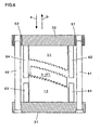
- FIG. 6 is a sectional view of a mold apparatus for the double-sided Fresnel lens according to a first example of the present invention.
- the reference numeral 3 designates the double-sided Fresnel lens shown in FIG. 5 , 11 and 12 the upper mold and the lower mold for transferring the Fresnel facets, respectively, 31 and 32 frame plates for the upper and lower molds that are integrally fixed to the upper and lower molds, respectively.
- the reference numerals 41 and 42 designate guide pins for controlling the mold opening/closing direction, respectively, 51 and 52 guide bushes that engages the guide pins 41 and 42, respectively, and 61, 62, 63 and 64 stroke limiters for controlling the press stroke end.
- the guide pins 41 and 42 inserted and fixed to the frame plate 31 are engaged by the guide bushes 51 and 52 inserted and fixed to the frame plate 32 such that a small gap exists between the guide pin 41 and the guide bush 51 and between the guide pin 42 and the guide bush 52, and the guide pins 41 and 42 can move smoothly.
- a mold apparatus shown in FIG. 6 are structured for the double-sided Fresnel lens. Accordingly, to operate the mold apparatus of FIG. 6 , a press machine (not shown in the drawing) is used that includes two pressing plates. The pressing plates lineally moves forward and backward, and have respective flat surfaces vertical to the forward and backward moving directions of the pressing plates. The pressing plates are fixed at the bed side and the ram side. The mold for the double-sided Fresnel lens is placed between the two pressing plates, the frame plate 31 is fixed to one pressing plate of the press machine, and the frame plate 32 is fixed to the other pressing plate of the press machine. Thereby, it is possible to open and close the mold apparatus for the double-sided Fresnel lens by the stroke of the press machine.
- the arrows "a" and “b” designate the closing direction and the opening direction.
- the following processes are performed.
- the molds 11 and 12 are separated from each other by the stroke of the press machine to open the mold apparatus in the direction "b".
- the thermally softened thermoplastic transparent resin plate 7 is placed between the molds 11 and 12.
- the press machine is promptly operated to close the mold apparatus in the direction "a” so that the resin plate 7 can be sandwiched and pressed by the molds 11 and 12.
- the resin plate 7 is entirely curved into a spherical surface shape, and the Fresnel facet is transferred on each side of the resin plate.
- a thickness of the molded product can be controlled by the stroke limiters 61 and 62, and the stroke limiters 63 and 64. In the state where the stroke of the press machine is pressed and extended up to the position of the stroke limiters, the resin plate is held until the resin is cooled and hardened to obtain the double-sided Fresnel lens 3.
- a thickness of the thermoplastic resin plate before pressing is determined based on heating condition, a resin material, and pressing force that is applied when the stroke of the press machine is completely extended up to the stroke limiters of the mold so as to obtain the appropriately transferred Fresnel lens having a predetermined thickness. Further, in the case of fabricating a double-sided Fresnel lens that has inhomogeneous thickness, it is preferable to use a thermoplastic resin plate that has the corresponding inhomogeneous thickness distribution. The condition of temperature of the mold and the thermoplastic resin at the time of the pressing, and the condition of a pressing speed and a pressing force are appropriately determined in accordance with a material of the thermoplastic resin plate.
- thermoplastic resin plate 7 materials other than PMMA (polymethylmethacrylate) was used as a transparent thermoplastic resin plate 7.
- TPX polymethylpentene made by Mitui Kagaku Inc.
- Cytop a fluorinated resin made by Asahi Garasu Inc.
- ZEONEX cycloolefin resin made by Nihhon Zeon Inc.
- Pellets of TPX was put in a heat insulation glass beaker, and melted in a vacuum dry furnace to make the TPX material for testing shown in FIG. 7 .
- An annealing process for 100 minutes was performed on this TPX material in a dry furnace in which heated air of 180 degrees centigrade flowed.
- the entire surface of the TPX material became yellow-tinged and sticky.
- the hardness of the TPX material did not change, and was equal to the hardness at a normal temperature.
- a test at a temperature higher than 180 degrees centigrade was not performed because the surface became sticky at 180 degrees centigrade.
- the Cytop material was put in the dry furnace in which heated air of 180 degrees centigrade flowed. As a result, the Cytop material was so softened that the Cytop material was able to be twisted and bent. Since the thickness of the Cytop material was only 10 mm, the press molding by using the mold heated to 70 degrees centigrade was performed on three Cytop materials put on top of each other as shown in FIG. 8A . As a result, a groove shape as shown in FIG. 8B was transferred.
- Pellets of ZEONEX were put in a heat insulation glass beaker, and melted in the vacuum dry furnace, and was then solidified.
- the thus-solidified ZEONEX material was used for the hot press molding experiment.
- the test ZEONEX material having a thickness of 10 mm that was cut off from a round bar was used for annealing experiment. In the dry furnace in which heated air of 180 degrees centigrade flowed, the annealing process for 100 minutes was performed on the ZEONEX material cut off from the round bar. As a result, the surface of the ZEONEX material was softened, but the inside middle part of the ZEONEX material was not softened, so that the crack was generated when the press molding was performed on the ZEONEX material.
- FIGS. 9C and 9D are photographs of the ZEONEX material folded like a waffle, showing the softness of the material.
- foam was generated on the ZEONEX material. It was difficult to soften the ZEONEX material, and a condition for suppressing the foam was not found.
- the ZEONEX material had elasticity like acryl, and did not become soft like rubber.
- the press transfer was performed in accordance with a melting speed of the resin. Since the falling speed of the upper mold was not controlled, the press transfer was performed depending on the speed at which oil was discharged by oil pressure applied by the weight of the upper mold, while melting the material. As a result, the surface of the ZEONEX material became completely fluid like a hamburger, the groove transfer was good, and the transparency was maintained as shown in FIGS. 10A, 10B and 10C . However, foam was generated. It was understood that adjusting of the mold falling speed and the control of the cooling speed were important.
- the present invention is not limited to the above-described embodiment, and various modifications can be made without departing from the scope of the present invention.
- the present invention can be applied to a general manufacturing method of the double-sided Fresnel lens other than the method in which a plurality of tablet slice segment lenses are manufactured and assembled into the double-sided Fresnel lens.
- the pressing instead of the upper and lower molds located at the upper and lower positions, the pressing may be carried out in the horizontal direction.
- the upper mold 11 has the upper transfer surface 11a and the lower transfer surface 12a that engage the upper surface and the lower surface of the resin plate 7 for the tablet slice segment lens 3, respectively.
- the transparent thermoplastic resin plate 7 is pressed by the upper mold 11 and the lower mold 12 so that the resin plate 7 can be curved.
- the both-side lens surfaces 5 and 6 of the segment lens 3 can be transferred to the upper surface and the lower surface of the resin plate. In this manner, it is possible to efficiently manufacture the tablet slice segment lens that constitutes a large, double-sided, curved Fresnel lens.
- thermoplastic resin plate 7 held at a temperature higher than the softening temperature of the resin plate 7 and lower than the melting temperature of the resin plate 7 is pressed by a predetermined pressure. Thereby, surface roughness becomes small, so that the high transparency can be obtained. Further, it is possible to achieve highly precise molding, obtaining high performance lens function.
- a double-sided Fresnel lens that can be manufactured by the present invention includes a circular, flat-plate-shaped Fresnel lens having a homogeneous thickness and a concentric groove, a Fresnel lens having a curved surface, a Fresnel lens having an inhomogeneous thickness, a Fresnel lens segment having only a part of a concentric groove, the combination of these Fresnel lenses, i.e., a Fresnel lens segment having a curved surface and an inhomogeneous thickness, and various complicated Fresnel lenses. According to the present invention, even a large Fresnel lens of which complete size is difficult to manufacture can be manufactured by fabricating divided segment lenses and bonding segment lenses, for
Landscapes
- Engineering & Computer Science (AREA)
- Mechanical Engineering (AREA)
- Physics & Mathematics (AREA)
- General Physics & Mathematics (AREA)
- Optics & Photonics (AREA)
- Health & Medical Sciences (AREA)
- Manufacturing & Machinery (AREA)
- Ophthalmology & Optometry (AREA)
- Moulds For Moulding Plastics Or The Like (AREA)
- Casting Or Compression Moulding Of Plastics Or The Like (AREA)
- Shaping Of Tube Ends By Bending Or Straightening (AREA)
Abstract
Description
- The present invention relates to a method and apparatus for manufacturing a large, double-sided, curved Fresnel lens that has a Fresnel groove on each surface.
-
FIG. 1A schematically shows a large, double-sided, curved Fresnel lens. It is proposed to use an optical system having two large, double-sided, curved Fresnellenses 2 and 2' for imaging in order to observe light (Cherenkov radiant ray) generated from high-energy particles at the time the high-energy particles fall in the atmosphere from outside the earth. By observing Cherenkov radiant ray, it is possible to measure strength, a wavelength and energy of an elementary particle that falls to the earth. - The large, double-sided, curved Fresnel
lenses 2 and 2' are launched together with a space shuttle into a stationary orbit of the earth to observe elementary particles at the range corresponding to the area of a diameter of about 600 km on the earth's surface. A very wide-sighted refractive optical system that can measure elementary particles includes two large, double-sided, curved Fresnellenses 2 and 2' each of which has a diameter of 2500 mm. One Fresnellens 2 includes two spherical surfaces S1 and S2 that have radii of 4099 mm and that are separated from each other by the distance of 20 mm in the optical axis direction. Fresnel grooves are formed on the surfaces S1 and S2, respectively. - The other Fresnel lens 2' includes two spherical surfaces S4 and S5 that have radii of 2555 mm and that are separated from each other by the distance of 20 mm in the optical axis direction. Fresnel grooves are formed on the surfaces S4 and S5.
- In order to manufacture the large, double-sided, curved Fresnel
lenses 2 and 2' having the diameters of 2500 mm, it is necessary to prepare a ultra-precise machining apparatus having a large rotary table of which diameter is no smaller than 2500 mm. Further, in the future, when a further larger, double-sided, curved Fresnel lens is required, the ultra-precise machining apparatus has to be made larger in size. In addition, a reinforcing tool needs to be attached to the large lens to increase the lens strength. Therefore, it is not easy and realistic to develop such a large ultra-precise machining apparatus. - For this reason, as schematically shown in
FIGS. 1A and 1B , it is assumed to divide the large, double-sided, curved Fresnellenses 2 and 2' into a plurality ofsegment lenses 3. That is, it can be considered to manufacture a predetermined number ofsegment lenses 3 having specific sizes. In this example, three or four types ofsegment lenses 3 needs to be manufactured. - Specifically, in the example of
FIG. 1A , each of the twolenses 2 and 2' are assembled by arranging acenter lens 4 having a diameter of 1500 mm, twenty-four inside tabletslice segment lenses 3 and twenty-four outside tabletslice segment lenses 3 each of which corresponds to a circle part equally divided from one circle by 15 degrees. In this manner, by manufacturing small components and putting them together, it is possible to ease transportation difficulty arising when one large Fresnel lens is manufactured. - One tablet
slice segment lens 3 needs to be formed such that theback sides lens surfaces segment lens 3 needs to have an entirely uniform thickness "t" of 20 mm in the direction of the lens optical axis Z. Further, thelens 3 needs to have an entire shape of a surface of revolution around the optical axis Z, and the optical axis Z of the Fresnel surface at the front side needs to conform to the optical axis Z of the Fresnel surface at the back side. Additionally, the height of theback sides lens 3 is indicated by "h" ofFIG. 1C . - Furthermore, the Fresnel lens is required to have high transparency, highly precise Fresnel lens groove, and high lens quality because of its use application.
- The Fresnel lens has the structure in which refractive surfaces are distributed to narrow band-shaped regions with the refractive surfaces being flat. Since the outline of the Fresnel lens is thin plate-shaped, it is advantageous to make good use of a small volume and light weight of the Fresnel lens. A mold having Fresnel lens transfer groove engraved on the flat surface thereof is used together with a flat plate for sandwiching a Fresnel lens material between the mold and the flat plate to fabricate the Fresnel lens by heat pressing. Accordingly, the Fresnel lens is formed on the one side surface of the material.
- A single-sided Fresnel lens is known from
JP-A-2001 047 523 - Recently, in order to take more advantage of characteristics of the thin plate-shaped Fresnel lens and more freely design the Fresnel lens, it has been desired to form the Fresnel lenses on both sides of a curved plate. Two plate materials each of which has the Fresnel lens surface on one side thereof are combined to each other on the other flat surfaces thereof to assemble a thin, flat, double-sided, plate-shaped Fresnel lens.
- However, there has not been a mold by which the Fresnel grooves are formed on both sides of a curved plate. Accordingly, it has been difficult to produce a curved lens having Fresnel grooves on both sides thereof.
- The present invention was made to satisfy the above desires. It is an object of the present invention to provide a method and apparatus for precisely manufacturing a tablet slice segment lens that constitutes a large, double-sided, curved Fresnel lens with the segment lens being highly transparent.
- According to the present invention, there is provided a method of manufacturing a large double-sided curved Fresnel lens as defined in attached
claim 1, the method comprising; a machining step (A) of performing ultra-precise three-dimensional machining on a material to make an upper mold having an upper transfer surface that engages an upper surface of a thermoplastic resin plate, and performing ultra-precise three-dimensional machining on a material to make a lower mold having a lower transfer surface that engages a lower surface of the thermoplastic resin plate; and a hot press molding step (B) of pressing the thermoplastic resin plate between the upper and lower molds by a predetermined pressure with the resin plate being held at a temperature higher than a softening temperature thereof and lower than a melting temperature thereof so that the thermoplastic resin plate is curved, and both upper and lower transfer surfaces for the double-sided Fresnel lens are respectively transferred to the upper surface and the lower surface of the thermoplastic resin plate. - Further, according to the present invention, there is provided an apparatus that manufactures a large double-sided curved Fresnel lens according to the features of attached
claim 4, the apparatus comprising: a machining tool for making an upper mold and a lower mold ; the upper mold having an upper transfer surface that engages an upper surface of a thermoplastic resin plate; the lower mold having a lower transfer surface that engages a lower surface of the thermoplastic resin plate; and a hot press machine with heating means that holds the thermoplastic resin plate at a temperature higher than a softening temperature thereof and lower than a melting temperature thereof, and presses the held thermoplastic resin plate between the upper and lower molds by a predetermined pressure to curve the thermoplastic resin plate and transfer both lens surfaces for the double-sided Fresnel lens to the upper and lower surfaces of the thermoplastic resin plate, respectively. - In the method and apparatus, the upper mold has the upper transfer surface that engages the upper surface of the resin plate, and the lower mold has the lower transfer surface that engages the lower surface of the resin plate. The thermoplastic resin is pressed between the upper mold and the lower mold so that the resin plate can be curved, and at the same time, both lens surfaces for the double-sided Fresnel lens can be transferred to the upper and lower surfaces of the resin plate. Thereby, it is possible to efficiently manufacture the double-sided curved Fresnel lens.
- Furthermore, the thermoplastic resin plate held at a temperature higher than the softening temperature and lower than the melting temperature is pressed by a predetermined pressure. Thereby, a small roughness of the lens surface can be obtained, achieving high transparency. Therefore, it is possible to obtain a lens function of high performance.
- In the above method, in the machining step (A), preferably, shapes of back sides of the double-sided Fresnel lens are respectively formed in the upper transfer surface and the lower transfer surface approximately in a direction parallel to the rotational axis. Thereby, it is possible to decrease molding resistance when shaping the back side part in the resin plate by the hot pressing. Furthermore, it is possible to suppress the flow of the resin plate with high precision.
- Moreover, according to the present invention, there is provide an apparatus that manufactures a large double-sided Fresnel lens, comprising: molds each having a Fresnel facet for the large double-sided Fresnel lens; and a press machine that simultaneously presses both surfaces of a thermoplastic resin plate by the molds with the thermoplastic resin plate being held at a temperature higher than a softening temperature thereof and lower than a melting temperature thereof.
- Furthermore, the above apparatus preferably comprises: mold frames to which the molds are fixed, respectively; a stroke guide that guides a press stroke in an optical direction of the Fresnel lens such that the molds move to and from each other in the optical direction; and a stroke limiter that controls the press stroke.
- In this apparatus, the upper and lower molds are installed on the press machine, and the upper and lower molds are separated from each other by the stroke of the press machine. Then, the thermoplastic resin plate that has been heated to a temperature higher than the softening temperature and lower than the melting temperature is placed between the upper mold and the lower mold, and the upper mold and the lower mold are moved to approach each other in the direction of the optical axis by the stroke of the press machine. When the stroke reaches the position of the stroke limiters, the movement of the upper and lower molds is stopped. At this time, the facets of the upper and lower molds are transferred to both surfaces of the thermoplastic resin plate. The molds and the resin plate are held in this state until the molds and the resin plate are cooled to a room temperature. Thereafter, the molds are separated to obtain the product for the double-sided Fresnel lens to both sides of which the Fresnel grooves are respectively transferred.
- Other objects, advantages and features of the present invention will become apparent from the following description with reference to the attached drawings.
-
-
FIGS. 1A, 1B and 1C are illustrations showing a structure of a large, double-sided, curved Fresnel lens related to the present invention; -
FIGS. 2A and 2B show an apparatus for manufacturing the large, double-sided Fresnel lens according to an embodiment of the present invention; -
FIGS. 3A and 3B show an apparatus for fabricating a mold for the large, double-sided Fresnel lens, which is not part of the present invention; -
FIG. 4 is an illustration schematically showing position control in the apparatus shown inFig. 3 . -
FIG. 5 is a perspective view showing a segment of a double-sided, spherical Fresnel lens having inhomogeneous thickness; -
FIG. 6 is a sectional view of a mold apparatus for the double-sided Fresnel lens according to a first example of the present invention; -
FIG. 7 is a photograph showing an appearance of a TPX material; -
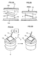
FIGS. 8A and 8B are illustrations showing an appearance before pressing, and an appearance after pressing, respectively; -
FIGS. 9A through 9D are photographs showing appearances of ZEONEX materials; and -
FIGS. 10A, 10B and 10C are photographs showing the ZEONEX material before and after pressing. - In the following, a preferred embodiment of the present invention will be described with reference to the drawings. The same reference numerals are attached to the same parts in the drawings.
-
FIGS. 2A and 2B show an apparatus for manufacturing a large, double-sided, curved Fresnel lens according to an embodiment of the present invention. The double-sided Fresnel lens means a lens that has Fresnel grooves on both sides thereof.FIG. 2A shows a state before pressing, andFIG. 2B shows a state after pressing. The manufacturing apparatus ofFIGS. 2A and 2B thermally presses a segment lens, and has anupper mold 11, alower mold 12, and ahot press machine 14. - The
upper mold 11 has anupper transfer surface 11a that engages an upper surface of aresin plate 7 for a tabletslice segment lens 3 divided from a large, double-sided,curved Fresnel lens 2 or 2' shown inFIG. 1A . Thelower mold 12 has alower transfer surface 12a that engages a lower surface of theresin plate 7. - The
hot press machine 14 has aheater plate 14a, maintains the temperature of the transparentthermoplastic resin plate 7 to be higher than the softening temperature of theplate 7 and lower than the melting temperature of theplate 7, and presses theresin plate 7 sandwiched between the upper andlower molds resin plate 7 is curved to have a desired shape, and theFresnel lens surfaces resin plate 7, respectively. - The
thermoplastic resin plate 7 is preferably PMMA (polymethylmethacrylate). PMMA is a transparent thermoplastic resin that is formed by polymerizing methylmethacrylate. PMMA has a refractive index of 1.48 to 1.52, a softening temperature of 71 degrees centigrade to 107 degrees centigrade, and fine optical characteristics. - A method of manufacturing the large, double-sided, curved Fresnel lens according to the embodiment of the present invention is performed by using the apparatus shown in
FIGS. 2A and 2B , and includes an ultra-precise three-dimensional machining step (A) and a hot press molding step (B). - In the ultra-precise three-dimensional machining step (A), the
upper mold 11 and thelower mold 12 are fabricated by ultra-precise three-dimensional machining so as to have theupper transfer surface 11a and thelower transfer surface 12a, respectively. - In the hot press molding step (B), the temperature of the transparent
thermoplastic resin plate 7 is maintained to be higher than the softening temperature and lower than the melting temperature, theresin plate 7 is pressed between the upper andlower molds resin plate 7 can be curved, and the lens surfaces for thesegment lens 3 can be transferred to both sides of theresin plate 7, respectively. - In the case where the
thermoplastic resin 7 is PMMA (polymethylmethacrylate), a temperature higher than the softening temperature and lower than the melting temperature ranges from 150 degrees centigrade to 180 degrees centigrade, for example. Accordingly, before pressing, the upper andlower molds resin plate 7 is also preheated to a temperature approximately equivalent to the temperature of themolds heated molds resin plate 7 is too low, the molding resistance becomes too large, and the surface becomes rougher. On the other hand, when the temperature of theheated molds resin plate 7 is too high, the softened material of theresin plate 7 becomes more fluid, so that the shape precision is deteriorated. - The predetermined pressure for pressing is 20 tons to 100 tons in the above example, and this pressure corresponds to a surface pressure of about 0.02 t/cm2 to 0.1 t/cm2. Further, after the pressing, in the state where the
resin plate 7 is pressed, themolds resin plate 7 are gradually cooled to a normal temperature. This gradual cooling in the pressed state enables highly precise molding. - Before the hot press molding step (B), the similar heat pressing step may be performed to only curve the
resin plate 7. Alternatively, by other methods other than the heat pressing, only the curving of theresin plate 7 may be performed in advance. -
FIGS. 3A and 3B show an apparatus for manufacturing the upper andlower mold FIG. 3A shows a state before the machining, andFIG. 3B shows a machining state. This manufacturing apparatus three-dimensionally machines a mold with very high precision, and includes a rotary table 16 and anultra-precise machining device 18. - The rotary table 16 rotates a
mold material 10 at a high speed around a rotational axis C parallel to the optical axis of the large, double-sided,curved Fresnel lenses 2 and 2'. Theultra-precise machining device 18 numerically controls amachining tool 13 in the directions of the axes X and Y orthogonal to the axis C and in the axis Z direction parallel to the axis C. A sintered diamond bite or a single-crystalline diamond bite is used as themachining tool 13. - In the method according to the embodiment, in the ultra-precise three-dimensional machining step (A), by using the apparatus of
FIGS. 3A and 3B , themold material 10 is rotated at a high speed around the axis C parallel to the optical axis of the large, double-sided,curved Fresnel lenses 2 and 2', and themachining tool 13 is numerically controlled in the directions of the axes X and Y orthogonal to the axis C and in the direction of the axis Z parallel to the axis C so that themold material 10 can be engraved to have the transfer surfaces 11a and 12a. -
FIG. 4 schematically shows the position control of this apparatus, which is not part of the present invention. As shown inFIG. 4 , "O" represents a rotational center of the rotary table 16, "O'" represents the center of the double-sided Fresnel lens, "R0" represents the distance between the center O and the center O', "f(r)" represents a shape (e.g., sphere) of a lens base, and "δ" represents a displaced angle around the center O' of the double-sided Fresnel lens. The position control with respect to the axes X, Y and Z and the rotational axis C is performed based on the following equations:


- The
mold material 10 is a material for theupper mold 11 and thelower mold 12, and is preferably a very hard material such as a metal suitable to the press molding. The position control of the three-axis numerical control in the directions of the axes X, Y and Z is preferably performed at a speed of about 1 m/min to 2 m/min while maintaining high position precision of about 10 nm. On the other hand, the position control of the axis C is performed at a higher speed, preferably, at a speed of 1 rpm to 3 rpm (360 deg/min to 1080 deg/min) corresponding to the peripheral velocity of several meters per minute. Preferably, the numerical control for the axis C is also performed at the same time the numerical control for the directions of the axes X, Y and Z is performed. However, as long as the position control for the axis C can be synchronized with the position control for the axes X, Y and Z, it is not necessary to perform the numerical position control for the axis C. - In the case of the conventional three-axis numerical control machining, when high position precision is maintained, a moving speed of the
machining tool 13 ranges from about 1 m/min to 2 m/min. Accordingly, such a low speed machining can produce only a rough surface and cannot produce a smooth surface. However, the mold material is rotated at a high speed around the axis C by the rotary table 16, so that the speed of machining the mold material can be raised to a speed equal to or higher than several meters per minute with high precision being maintained, compared to the conventional three-axis numerical control machining. In this manner, it is possible to produce the mold of which machined surface has a mirror-like roughness of about Ry 100 nm. - Furthermore, according to the apparatus, which is not part of the present invention, without using a large rotary table having a rotational center that corresponds to the center O' of the double-sided Fresnel lens, the small rotary table 16 having the rotational center O shown in
FIG. 4 is used in the four-axis control. Thereby, it is possible to achieve the machining of a groove having any shape such as a concentric Fresnel groove of the large Fresnel lens. - In addition, in the ultra-precise three-dimensional machining step (A), the mold is manufactured such that the shapes of the
back sides back sides curved Fresnel lens 2 or 2', theback sides - Next, a first example of the present invention will be described.
- A lens material of the large, double-sided, curved Fresnel lens shown in
FIG. 1A is an ultraviolet ray transparency grade plate made of PMMA (polymethylmethacrylate) and having a thickness of 20 mm. In this example, a plate material made of oxygen-free copper was three-dimensionally machined with very high accuracy to fabricate amold 11, and then, thismold 11 was used to transfer Fresnel surface on a lens material for a tabletslice segment lens 3 by taking advantage of the thermoplastic property of the lens material. - An overall size of the tablet
slice segment lens 3 was cut out from the PMMA material, and the cut lens material for thesegment lens 3 was preheated in a furnace. Thereafter, the heated lens material was thermally pressed by using themold 11 attached to the hot press machine to transfer the spherical surface and the Fresnel lens shape on the lens material. Then, the lens material was taken from the hot press machine, and cooled. After cooling, an excess part was cut off from the pressed lens material. - The ultra-precise mold for hot press molding needs to be fabricated for each of the four types of the segment lenses, but the basic structure of the mold for each type of the segment lens is the same. These molds were designed and fabricated by taking into account the following matters (1) to (4).
- (1) For the Fresnel groove on the both sides of the material (regarding a mechanism for aligning the upper position and the lower position), the consideration was given to smooth movement in the operational temperature range of the hot press molding, an appropriate clearance between a guide post and a guide bush, material selection of the guide post and the guide bush, a coefficient of thermal expansion of the guide relative to the position pitch, and designing of the guide post and the guide push.
- (2) For the curved shape (regarding a locking mechanism), the consideration was given to smooth movement in the operational temperature range of the hot press molding, an appropriate countermeasure for component force generated at the time of the hot press molding, maintaining of a free state at the time of starting the press molding, a locking mechanism that starts to function from a position where the displacement is generated, and complete receiving of the displacement at the time of finishing the pressing.
- (3) For an uneven thickness (regarding a temperature adjusting mechanism), the consideration was given to a stable temperature management in the operational temperature range of the hot press molding.
- (4) For precise hot press molding (regarding a spacer mechanism), the consideration was given to different processes for the uneven thickness and the both-side Fresnel grooves.
- The Fresnel transfer surface of the mold was machined by using a large ultra-precise machining apparatus. Thereby, the mold was fabricated and adjusted.
- Then, Ni-coating process was performed on the thus-machined Fresnel transfer lens surface to prevent generation of corrosion. The thickness of this Ni-coating was about 4 µm, and the surface roughness was degraded to about Ry 150 nm.
- In the hot press, the temperature is not raised to a degree of the temperature of injection molding that melts a resin to be fluid. The hot press is a molding method that uses pressing fluidity (plastic deformation) in the softened state. Compared to the injection molding, in the hot press, temperature range between the heating and cooling is narrower than in the injection molding, and the temperature raising and lowering rate of the heating and the cooling is smaller than in the injection molding. Accordingly, the product made by the hot press has smaller inside remaining stress due to the heat and becomes more homogeneous. However, in the hot press, it is difficult to perform greatly deforming molding in which the molding cannot be performed unless the material is greatly fluid and deformed. Furthermore, if the Fresnel facet engraved by mirror finish cutting is thermally transferred to the lens material completely by a high pressure (transfer rate is 100 %), it becomes difficult to remove the lens material adhering to the mold from the mold.
- Conventionally, in the case of manufacturing the Fresnel lens by the thermal transfer, the base shape of the lens is plane, the notching pitch is equal to or smaller than 0.5 mm (the height of the back side is also equal to or smaller than 0.5 mm), and the Fresnel lens surface is formed on only the one side. Furthermore, a remaining thermal stress is generated in the material when molding the material into a plate shape, and deformation size change is generated, accompanying release of the remaining thermal stress when heating for the hot press molding. Therefore, it is necessary to correct the mold shape.
- On the other hand, in this example of manufacturing the large, double-sided, curved Fresnel lens, the height of the back side of the Fresnel lens needs to be uniformly 1 mm, the thickness of the lens in the optical axis direction needs to be uniformly 20 mm over the entire surface, the lens needs to have a shape of a spherical surface, and the optical axis of the Fresnel surface formed on the one side needs to conform to the optical axis of the Fresnel surface formed on the other side. In other words, a deep groove of which back side height is 1 mm needs to be transferred, and in order to form the uniform lens thickness of 20 mm in the optical axis direction, the thickness in the direction vertical to the lens surface needs to change depending on the radial position of the lens, that is, the plate material having uniform thickness of 20 mm needs to be deformed to have an uneven thickness in the direction vertical to the surface. Furthermore, it is necessary to take into account deforming of the spherical surface shape due to thermal contraction, and the spherical radius change (deforming of the spherical surface) due to the weight of the lens itself when the lens is removed from the mold.
- Taking the above-described matters into account, the molding experiment was performed. In this experiment, the segment lens was made by the hot press molding. This segment lens had a fine surface roughness and very high transparency. Further, it was confirmed that the Fresnel lens groove was transferred to the segment lens with high precision. In addition, from the image formed by the lens, it was confirmed that the lens had the high precision lens function.
- In the following, the hot press machine for the segment lens shown in
FIGS. 2A and 2B that was used in the first and second example will be described in detailed. -
FIG. 5 is a perspective view showing one example of a Fresnel lens. This Fresnel lens ofFIG. 5 has features that this lens is a double-sided Fresnel lens segment, and the standard surfaces of the both sides of the lens are spherical, and this lens is one of a plurality of segment lenses that are assembled to form one Fresnel lens. -
FIG. 6 is a sectional view of a mold apparatus for the double-sided Fresnel lens according to a first example of the present invention. InFIG. 6 , thereference numeral 3 designates the double-sided Fresnel lens shown inFIG. 5 , 11 and 12 the upper mold and the lower mold for transferring the Fresnel facets, respectively, 31 and 32 frame plates for the upper and lower molds that are integrally fixed to the upper and lower molds, respectively. Further, inFIG. 6 , thereference numerals frame plate 31 are engaged by theguide bushes frame plate 32 such that a small gap exists between theguide pin 41 and theguide bush 51 and between theguide pin 42 and theguide bush 52, and the guide pins 41 and 42 can move smoothly. - A mold apparatus shown in
FIG. 6 are structured for the double-sided Fresnel lens. Accordingly, to operate the mold apparatus ofFIG. 6 , a press machine (not shown in the drawing) is used that includes two pressing plates. The pressing plates lineally moves forward and backward, and have respective flat surfaces vertical to the forward and backward moving directions of the pressing plates. The pressing plates are fixed at the bed side and the ram side. The mold for the double-sided Fresnel lens is placed between the two pressing plates, theframe plate 31 is fixed to one pressing plate of the press machine, and theframe plate 32 is fixed to the other pressing plate of the press machine. Thereby, it is possible to open and close the mold apparatus for the double-sided Fresnel lens by the stroke of the press machine. - In
FIG. 6 , the arrows "a" and "b" designate the closing direction and the opening direction. To mold the double-sided Fresnel lens made of a thermoplastic transparent resin by using the double-sided Fresnel lens mold apparatus installed in the press machine, the following processes are performed. Themolds transparent resin plate 7 is placed between themolds resin plate 7 can be sandwiched and pressed by themolds resin plate 7 is entirely curved into a spherical surface shape, and the Fresnel facet is transferred on each side of the resin plate. A thickness of the molded product can be controlled by thestroke limiters stroke limiters sided Fresnel lens 3. - In the above example, means for heating and cooling the
molds molds - According to the above example, a thickness of the thermoplastic resin plate before pressing is determined based on heating condition, a resin material, and pressing force that is applied when the stroke of the press machine is completely extended up to the stroke limiters of the mold so as to obtain the appropriately transferred Fresnel lens having a predetermined thickness. Further, in the case of fabricating a double-sided Fresnel lens that has inhomogeneous thickness, it is preferable to use a thermoplastic resin plate that has the corresponding inhomogeneous thickness distribution. The condition of temperature of the mold and the thermoplastic resin at the time of the pressing, and the condition of a pressing speed and a pressing force are appropriately determined in accordance with a material of the thermoplastic resin plate.
- In addition to the first example, another hot press molding experiment was performed in which materials other than PMMA (polymethylmethacrylate) was used as a transparent
thermoplastic resin plate 7. TPX (polymethylpentene made by Mitui Kagaku Inc.), Cytop (a fluorinated resin made by Asahi Garasu Inc.), and ZEONEX (cycloolefin resin made by Nihhon Zeon Inc.) were used as the materials other than PMMA. - Pellets of TPX was put in a heat insulation glass beaker, and melted in a vacuum dry furnace to make the TPX material for testing shown in
FIG. 7 . An annealing process for 100 minutes was performed on this TPX material in a dry furnace in which heated air of 180 degrees centigrade flowed. As a result, the entire surface of the TPX material became yellow-tinged and sticky. However, the hardness of the TPX material did not change, and was equal to the hardness at a normal temperature. A test at a temperature higher than 180 degrees centigrade was not performed because the surface became sticky at 180 degrees centigrade. - For about three minutes, the Cytop material was put in the dry furnace in which heated air of 180 degrees centigrade flowed. As a result, the Cytop material was so softened that the Cytop material was able to be twisted and bent. Since the thickness of the Cytop material was only 10 mm, the press molding by using the mold heated to 70 degrees centigrade was performed on three Cytop materials put on top of each other as shown in
FIG. 8A . As a result, a groove shape as shown inFIG. 8B was transferred. - Pellets of ZEONEX were put in a heat insulation glass beaker, and melted in the vacuum dry furnace, and was then solidified. The thus-solidified ZEONEX material was used for the hot press molding experiment. Further, the test ZEONEX material having a thickness of 10 mm that was cut off from a round bar was used for annealing experiment. In the dry furnace in which heated air of 180 degrees centigrade flowed, the annealing process for 100 minutes was performed on the ZEONEX material cut off from the round bar. As a result, the surface of the ZEONEX material was softened, but the inside middle part of the ZEONEX material was not softened, so that the crack was generated when the press molding was performed on the ZEONEX material. In addition, foam was generated on the ZEONEX material. Next, the annealing process for 100 minutes was performed on the ZEONEX material in the dry furnace in which heated air of 240 degrees centigrade flowed. As a result, the ZEONEX material became completely fluid.
FIGS. 9C and 9D are photographs of the ZEONEX material folded like a waffle, showing the softness of the material. However, also in this case, foam was generated on the ZEONEX material. It was difficult to soften the ZEONEX material, and a condition for suppressing the foam was not found. The ZEONEX material had elasticity like acryl, and did not become soft like rubber. - The press transfer was performed in accordance with a melting speed of the resin. Since the falling speed of the upper mold was not controlled, the press transfer was performed depending on the speed at which oil was discharged by oil pressure applied by the weight of the upper mold, while melting the material. As a result, the surface of the ZEONEX material became completely fluid like a hamburger, the groove transfer was good, and the transparency was maintained as shown in
FIGS. 10A, 10B and 10C . However, foam was generated. It was understood that adjusting of the mold falling speed and the control of the cooling speed were important. - Thus, it was confirmed from the second example that the molding of the material other than PMMA (polymethylmethacrylate) was difficult, and PMMA was particularly suitable to the molding.
- The present invention is not limited to the above-described embodiment, and various modifications can be made without departing from the scope of the present invention. For example, the present invention can be applied to a general manufacturing method of the double-sided Fresnel lens other than the method in which a plurality of tablet slice segment lenses are manufactured and assembled into the double-sided Fresnel lens. Further, in the present invention, instead of the upper and lower molds located at the upper and lower positions, the pressing may be carried out in the horizontal direction.
- According to the manufacturing method and apparatus of the present invention, the
upper mold 11 has theupper transfer surface 11a and thelower transfer surface 12a that engage the upper surface and the lower surface of theresin plate 7 for the tabletslice segment lens 3, respectively. With this structure, the transparentthermoplastic resin plate 7 is pressed by theupper mold 11 and thelower mold 12 so that theresin plate 7 can be curved. At the same time, the both-side lens surfaces 5 and 6 of thesegment lens 3 can be transferred to the upper surface and the lower surface of the resin plate. In this manner, it is possible to efficiently manufacture the tablet slice segment lens that constitutes a large, double-sided, curved Fresnel lens. - The
thermoplastic resin plate 7 held at a temperature higher than the softening temperature of theresin plate 7 and lower than the melting temperature of theresin plate 7 is pressed by a predetermined pressure. Thereby, surface roughness becomes small, so that the high transparency can be obtained. Further, it is possible to achieve highly precise molding, obtaining high performance lens function. - According to the present invention, the heated and softened thermoplastic resin is pressed by using the press mold for a double-sided Fresnel lens. Thereby, it becomes possible to easily manufacture the doube-sided Fresnel lens that was conventionally difficult. A double-sided Fresnel lens that can be manufactured by the present invention includes a circular, flat-plate-shaped Fresnel lens having a homogeneous thickness and a concentric groove, a Fresnel lens having a curved surface, a Fresnel lens having an inhomogeneous thickness, a Fresnel lens segment having only a part of a concentric groove, the combination of these Fresnel lenses, i.e., a Fresnel lens segment having a curved surface and an inhomogeneous thickness, and various complicated Fresnel lenses. According to the present invention, even a large Fresnel lens of which complete size is difficult to manufacture can be manufactured by fabricating divided segment lenses and bonding segment lenses, for example.
- Thus, according to the manufacturing method and apparatus for a large, double-sided, curved Fresnel lens, with high precision, it is possible to mold a highly transparent tablet slice segment lens that constitutes the large, double-sided, curved Fresnel lens, and to achieve high performance lens function.
Claims (8)
- A method of manufacturing a large double-sided curved Fresnel lens(2, 2'), comprising:a machining step (A) of
performing ultra-precise three-dimensional machining on a material (10) to make an upper mold (11) having an upper transfer surface (11a) that engages an upper surface of a thermoplastic resin plate (7), and
performing ultra-precise three-dimensional machining on a material (10) to make a lower mold (12) having a lower transfer surface (12a) that engages a lower surface of the thermoplastic resin plate(7); anda hot press molding step (B) of pressing the thermoplastic resin plate (7) between the upper and lower molds (11 and 12) by a predetermined pressurewherein the resin plate(7) is held at a temperature higher than a softening temperature thereof and lower than a melting temperature thereof so that the thermoplastic resin plate (7) is curved, andboth upper and lower transfer surfaces (11a, 12a) for the double-sided Fresnel lens (2, 2') are respectively transferred to the upper surface and the lower surface of the thermoplastic resin plate (7). - The method according to claim 1, wherein in the machining step (A), each of the materials (10) for the upper and lower molds (11 and 12) is rotated around a rotational axis parallel to an optical axis of the large double-sided curved Fresnel lens (2, 2') at a high speed, and
a position of a machining tool (13) for the material (10) is numerically controlled in first and second directions orthogonal to the rotational axis and in a third direction parallel to the rotational axis so as to form the upper transfer surface (11a) and the lower transfer surface (12a). - The method according to claim 2, wherein in the machining step (A), shapes of back sides (5a, 6a) of the double-sided Fresnel lens (2, 2') are respectively formed in the upper transfer surface (11 a) and the lower transfer surface (12a) approximately in a direction parallel to the rotational axis.
- An apparatus that manufactures a large double-sided curved Fresnel lens (2, 2'), comprising:a machining, tool for making an upper mold (11) and a lower mold (12), the molds (11, 12) each having a Fresnel facet for the large double-sided curved Fresnel lens; anda hot press machine with heating means (14a) that simultaneously presses both surfaces of a thermoplastic resin plate (7) by using the molds (11, 12),wherein means are provided to hold the thermoplastic resin plate (7) at a temperature higher than a softening temperature thereof and lower than a melting temperature thereof.
- The apparatus according to claim 4, wherein the molds comprise:an upper mold (11) having an upper transfer surface (11a) that engages an upper surface of a thermoplastic resin plate (7);a lower mold (12) having a lower transfer surface (12a) that engages a lower surface of the thermoplastic resin plate (7);
- The apparatus according to claims 4 or 5, wherein the large double-sided Fresnel lens (2, 2') is a curved lens and the thermoplastic resin plate (7) may be curved in the hot press machine before transferring the lens surfaces (5, 6).
- The apparatus according to claim 6, wherein the thermoplastic resin plate (7) corresponds to a segment (3) of the large double-sided curved Fresnel lens (2, 2').
- The apparatus according to claim 4, the hot press machine comprising:mold frames (32, 31) to which the molds (11, 12) are fixed, respectively;a stroke guide (41, 42) that guides a press stroke in an optical direction of the Fresnel lens (2, 2') such that the molds (11, 12) move to and from each other in the optical direction; anda stroke limiter (61, 62, 63, 64) that controls the press stroke.
Applications Claiming Priority (3)
| Application Number | Priority Date | Filing Date | Title |
|---|---|---|---|
| JP2001370052 | 2001-12-04 | ||
| JP2001370052 | 2001-12-04 | ||
| PCT/JP2002/012628 WO2003047833A1 (en) | 2001-12-04 | 2002-12-03 | Method and device for manufacturing large curved double-sided fresnel lens |
Publications (3)
| Publication Number | Publication Date |
|---|---|
| EP1464463A1 EP1464463A1 (en) | 2004-10-06 |
| EP1464463A4 EP1464463A4 (en) | 2005-03-02 |
| EP1464463B1 true EP1464463B1 (en) | 2011-05-18 |
Family
ID=19179345
Family Applications (1)
| Application Number | Title | Priority Date | Filing Date |
|---|---|---|---|
| EP02786013A Expired - Lifetime EP1464463B1 (en) | 2001-12-04 | 2002-12-03 | Method and device for manufacturing large curved double-sided fresnel lens |
Country Status (5)
| Country | Link |
|---|---|
| US (1) | US7106528B2 (en) |
| EP (1) | EP1464463B1 (en) |
| JP (1) | JP4412712B2 (en) |
| AU (1) | AU2002354184A1 (en) |
| WO (1) | WO2003047833A1 (en) |
Families Citing this family (32)
| Publication number | Priority date | Publication date | Assignee | Title |
|---|---|---|---|---|
| JPWO2007123202A1 (en) * | 2006-04-20 | 2009-09-03 | 株式会社フジクラ | Display device and manufacturing method thereof, pattern display method, blind device and blind method |
| GB2447502B (en) * | 2007-03-15 | 2011-12-21 | Robert Edward Graham Dutton | Mould |
| US20090050255A1 (en) * | 2007-08-22 | 2009-02-26 | Xerox Corporation | Flexible imaging member belt seam smoothing process |
| US20100200740A1 (en) * | 2007-09-10 | 2010-08-12 | Inter-University Reserch Institute Corp High Energy Accelerator Research Organization | Method of molding amorphous perfluoro resin and optic devices |
| UA102854C2 (en) | 2008-06-30 | 2013-08-27 | Микробикс Байосистемз Инк. | Method and device for sorting of cells |
| JP5333986B2 (en) * | 2008-09-18 | 2013-11-06 | 株式会社リコー | Plastic optical element having fine pattern on optical surface |
| FR2945109B1 (en) * | 2009-05-04 | 2012-10-19 | Jean Xavier Marie Herzog | HORIZONTAL OPTICAL SOLAR SENSOR SYSTEM ELECTRO-THERMO GENERATOR |
| US8665439B2 (en) * | 2009-06-30 | 2014-03-04 | Microbix Biosystems, Inc. | Method and apparatus for limiting effects of refraction in cytometry |
| MX338778B (en) | 2011-02-15 | 2016-05-02 | Microbix Biosystems Inc | Methods, systems, and apparatus for performing flow cytometry. |
| US9625638B2 (en) | 2013-03-15 | 2017-04-18 | Cree, Inc. | Optical waveguide body |
| US9869432B2 (en) | 2013-01-30 | 2018-01-16 | Cree, Inc. | Luminaires using waveguide bodies and optical elements |
| US9291320B2 (en) | 2013-01-30 | 2016-03-22 | Cree, Inc. | Consolidated troffer |
| US9366396B2 (en) | 2013-01-30 | 2016-06-14 | Cree, Inc. | Optical waveguide and lamp including same |
| US9690029B2 (en) | 2013-01-30 | 2017-06-27 | Cree, Inc. | Optical waveguides and luminaires incorporating same |
| US10436969B2 (en) | 2013-01-30 | 2019-10-08 | Ideal Industries Lighting Llc | Optical waveguide and luminaire incorporating same |
| US9442243B2 (en) | 2013-01-30 | 2016-09-13 | Cree, Inc. | Waveguide bodies including redirection features and methods of producing same |
| US9798072B2 (en) | 2013-03-15 | 2017-10-24 | Cree, Inc. | Optical element and method of forming an optical element |
| US9920901B2 (en) | 2013-03-15 | 2018-03-20 | Cree, Inc. | LED lensing arrangement |
| US10502899B2 (en) * | 2013-03-15 | 2019-12-10 | Ideal Industries Lighting Llc | Outdoor and/or enclosed structure LED luminaire |
| US10379278B2 (en) * | 2013-03-15 | 2019-08-13 | Ideal Industries Lighting Llc | Outdoor and/or enclosed structure LED luminaire outdoor and/or enclosed structure LED luminaire having outward illumination |
| US10400984B2 (en) | 2013-03-15 | 2019-09-03 | Cree, Inc. | LED light fixture and unitary optic member therefor |
| US10436970B2 (en) | 2013-03-15 | 2019-10-08 | Ideal Industries Lighting Llc | Shaped optical waveguide bodies |
| US10209429B2 (en) | 2013-03-15 | 2019-02-19 | Cree, Inc. | Luminaire with selectable luminous intensity pattern |
| US9366799B2 (en) | 2013-03-15 | 2016-06-14 | Cree, Inc. | Optical waveguide bodies and luminaires utilizing same |
| KR20150049617A (en) * | 2013-10-30 | 2015-05-08 | (주)애니캐스팅 | Pattern molding apparatus for large area flat glass |
| US9464778B2 (en) | 2014-01-21 | 2016-10-11 | Cree, Inc. | Lighting device utilizing a double fresnel lens |
| US9840347B1 (en) | 2014-12-17 | 2017-12-12 | X Development LLX | Adhering modular elements for packaging structures |
| US9828128B1 (en) | 2014-12-17 | 2017-11-28 | X Development Llc | On-demand protective structures for packaging items in a container |
| US11719882B2 (en) | 2016-05-06 | 2023-08-08 | Ideal Industries Lighting Llc | Waveguide-based light sources with dynamic beam shaping |
| US10416377B2 (en) | 2016-05-06 | 2019-09-17 | Cree, Inc. | Luminaire with controllable light emission |
| EP3470202B1 (en) * | 2017-10-12 | 2021-08-18 | Essilor International | Injection molding with heat/cool cycle for making optical articles with a fresnel surface |
| JP7414826B2 (en) * | 2018-12-18 | 2024-01-16 | ルポルド アンド スティーブンズ インコーポレイテッド | Illuminated reticle system with Fresnel lens |
Family Cites Families (13)
| Publication number | Priority date | Publication date | Assignee | Title |
|---|---|---|---|---|
| JPS57109618A (en) * | 1980-12-27 | 1982-07-08 | Dainippon Printing Co Ltd | Both faces fresnel lens and its manufacture |
| JP2789195B2 (en) * | 1988-07-21 | 1998-08-20 | 大日本印刷株式会社 | Manufacturing method of plastic sheet |
| NL8901077A (en) * | 1989-04-28 | 1990-11-16 | Koninkl Philips Electronics Nv | OPTICAL EXPOSURE SYSTEM AND PROJECTION DEVICE EQUIPPED WITH SUCH A SYSTEM. |
| JPH02133327A (en) * | 1989-06-26 | 1990-05-22 | Canon Inc | Method for manufacturing optical elements |
| JPH05169464A (en) * | 1991-12-20 | 1993-07-09 | Dainippon Printing Co Ltd | Method for manufacturing lens sheet for screen |
| JPH06114860A (en) * | 1992-09-30 | 1994-04-26 | Toppan Printing Co Ltd | Production of lens sheet |
| JPH07148857A (en) * | 1993-11-26 | 1995-06-13 | Toppan Printing Co Ltd | Method for manufacturing plastic lens |
| JPH08227007A (en) * | 1995-02-21 | 1996-09-03 | Olympus Optical Co Ltd | Formation of surface shape of object and production of metal mold |
| JPH09216232A (en) * | 1996-02-09 | 1997-08-19 | Matsushita Electric Ind Co Ltd | Optical element molding die and method for manufacturing the same |
| JPH11983A (en) * | 1997-06-12 | 1999-01-06 | Toyoda Gosei Co Ltd | Decorative molding and its manufacture |
| JP2000079636A (en) * | 1998-07-09 | 2000-03-21 | Canon Inc | Fine processing method and device |
| JP2001047523A (en) * | 1999-08-10 | 2001-02-20 | Honda Motor Co Ltd | Mold for Fresnel lens and method for manufacturing Fresnel lens using this mold |
| JP3652182B2 (en) | 1999-09-24 | 2005-05-25 | キヤノン株式会社 | Diffraction grating processing method and processing apparatus |
-
2002
- 2002-12-03 WO PCT/JP2002/012628 patent/WO2003047833A1/en not_active Ceased
- 2002-12-03 EP EP02786013A patent/EP1464463B1/en not_active Expired - Lifetime
- 2002-12-03 AU AU2002354184A patent/AU2002354184A1/en not_active Abandoned
- 2002-12-03 US US10/496,151 patent/US7106528B2/en not_active Expired - Fee Related
- 2002-12-03 JP JP2003549063A patent/JP4412712B2/en not_active Expired - Fee Related
Also Published As
| Publication number | Publication date |
|---|---|
| AU2002354184A1 (en) | 2003-06-17 |
| JP4412712B2 (en) | 2010-02-10 |
| US7106528B2 (en) | 2006-09-12 |
| JPWO2003047833A1 (en) | 2005-04-14 |
| US20050007682A1 (en) | 2005-01-13 |
| EP1464463A4 (en) | 2005-03-02 |
| EP1464463A1 (en) | 2004-10-06 |
| WO2003047833A1 (en) | 2003-06-12 |
Similar Documents
| Publication | Publication Date | Title |
|---|---|---|
| US7106528B2 (en) | Method and apparatus for manufacturing large double-sided curved Fresnel lens | |
| US7143609B2 (en) | Low-temperature fabrication of glass optical components | |
| CN101041258B (en) | Apparatus and method for molding object with enhanced transferability of transfer face and object made by the same | |
| US4797144A (en) | Deep pressing mold and process for molded optical elements | |
| JP4686426B2 (en) | Optical lens, lens group, optical image collection device, and manufacturing method thereof | |
| CN1715224B (en) | Method for producing an optical element and substrate thereof | |
| JPH01106003A (en) | Lens element and manufacture thereof | |
| JP2002192568A (en) | Micro lens manufacturing method and micro lens array | |
| US6761046B2 (en) | Cold rolling of glass preforms | |
| Shu et al. | Fabrication of Fresnel lens arrays by a rapid non-isothermal imprinting process | |
| US11485665B2 (en) | Mould pair having alignment surfaces | |
| Xie et al. | Replication of thermoplastic polymer spherical lens array using microforged molding technique | |
| Zhou | Precision molding of microstructures on chalcogenide glass for infrared optics | |
| JPH0990151A (en) | Manufacture of v-groove optical connector base and manufacture of optical connector provided with the base | |
| US20100192635A1 (en) | Molding die and manufacturing method of optical element | |
| JPH0244033A (en) | Lens processing apparatus and lens | |
| JP2001163628A (en) | Manufacturing method of molded products | |
| JP3883634B2 (en) | Mold for press molding optical elements | |
| CN1939851B (en) | Perform for precise punch forming, manufacturing method thereof and manufacturing method of optical element | |
| JP5476993B2 (en) | Optical element manufacturing method and manufacturing apparatus | |
| JP2000281360A (en) | Optical blank for forming, production of optical blank for forming and method for forming optical parts | |
| JPS6195912A (en) | Molding method of microlens | |
| JP2019059228A (en) | Production method of prism, prism, and mold | |
| JPS61183132A (en) | Production of glass lens | |
| Zhang | Investigation of Optical Effects of Chalcogenide Glass in Precision Glass Molding and Applications on Infrared Micro Optical Manufacturing |
Legal Events
| Date | Code | Title | Description |
|---|---|---|---|
| PUAI | Public reference made under article 153(3) epc to a published international application that has entered the european phase |
Free format text: ORIGINAL CODE: 0009012 |
|
| 17P | Request for examination filed |
Effective date: 20040517 |
|
| AK | Designated contracting states |
Kind code of ref document: A1 Designated state(s): AT BE BG CH CY CZ DE DK EE ES FI FR GB GR IE IT LI LU MC NL PT SE SI SK TR |
|
| AX | Request for extension of the european patent |
Extension state: AL LT LV MK RO |
|
| RIC1 | Information provided on ipc code assigned before grant |
Ipc: 7B 23B 5/48 B Ipc: 7B 29D 11/00 B Ipc: 7B 29C 43/36 B Ipc: 7B 29C 33/42 - Ipc: 7B 29C 33/38 - Ipc: 7B 29C 43/02 A Ipc: 7G 02B 3/08 B |
|
| A4 | Supplementary search report drawn up and despatched |
Effective date: 20050114 |
|
| 17Q | First examination report despatched |
Effective date: 20050322 |
|
| 17Q | First examination report despatched |
Effective date: 20050322 |
|
| GRAP | Despatch of communication of intention to grant a patent |
Free format text: ORIGINAL CODE: EPIDOSNIGR1 |
|
| GRAS | Grant fee paid |
Free format text: ORIGINAL CODE: EPIDOSNIGR3 |
|
| GRAA | (expected) grant |
Free format text: ORIGINAL CODE: 0009210 |
|
| AK | Designated contracting states |
Kind code of ref document: B1 Designated state(s): DE GB |
|
| REG | Reference to a national code |
Ref country code: GB Ref legal event code: FG4D |
|
| REG | Reference to a national code |
Ref country code: DE Ref legal event code: R096 Ref document number: 60240099 Country of ref document: DE Effective date: 20110630 |
|
| PLBE | No opposition filed within time limit |
Free format text: ORIGINAL CODE: 0009261 |
|
| STAA | Information on the status of an ep patent application or granted ep patent |
Free format text: STATUS: NO OPPOSITION FILED WITHIN TIME LIMIT |
|
| 26N | No opposition filed |
Effective date: 20120221 |
|
| REG | Reference to a national code |
Ref country code: DE Ref legal event code: R097 Ref document number: 60240099 Country of ref document: DE Effective date: 20120221 |
|
| PGFP | Annual fee paid to national office [announced via postgrant information from national office to epo] |
Ref country code: DE Payment date: 20131127 Year of fee payment: 12 Ref country code: GB Payment date: 20131127 Year of fee payment: 12 |
|
| REG | Reference to a national code |
Ref country code: DE Ref legal event code: R119 Ref document number: 60240099 Country of ref document: DE |
|
| GBPC | Gb: european patent ceased through non-payment of renewal fee |
Effective date: 20141203 |
|
| PG25 | Lapsed in a contracting state [announced via postgrant information from national office to epo] |
Ref country code: DE Free format text: LAPSE BECAUSE OF NON-PAYMENT OF DUE FEES Effective date: 20150701 Ref country code: GB Free format text: LAPSE BECAUSE OF NON-PAYMENT OF DUE FEES Effective date: 20141203 |