EP1464451A1 - Bipedal walking type moving device; and walking control device and walking control method therefor - Google Patents
Bipedal walking type moving device; and walking control device and walking control method therefor Download PDFInfo
- Publication number
- EP1464451A1 EP1464451A1 EP20020805016 EP02805016A EP1464451A1 EP 1464451 A1 EP1464451 A1 EP 1464451A1 EP 20020805016 EP20020805016 EP 20020805016 EP 02805016 A EP02805016 A EP 02805016A EP 1464451 A1 EP1464451 A1 EP 1464451A1
- Authority
- EP
- European Patent Office
- Prior art keywords
- force
- walk
- biped walking
- gait
- mobile apparatus
- Prior art date
- Legal status (The legal status is an assumption and is not a legal conclusion. Google has not performed a legal analysis and makes no representation as to the accuracy of the status listed.)
- Granted
Links
Images



Classifications
-
- B—PERFORMING OPERATIONS; TRANSPORTING
- B25—HAND TOOLS; PORTABLE POWER-DRIVEN TOOLS; MANIPULATORS
- B25J—MANIPULATORS; CHAMBERS PROVIDED WITH MANIPULATION DEVICES
- B25J5/00—Manipulators mounted on wheels or on carriages
-
- B—PERFORMING OPERATIONS; TRANSPORTING
- B25—HAND TOOLS; PORTABLE POWER-DRIVEN TOOLS; MANIPULATORS
- B25J—MANIPULATORS; CHAMBERS PROVIDED WITH MANIPULATION DEVICES
- B25J13/00—Controls for manipulators
- B25J13/08—Controls for manipulators by means of sensing devices, e.g. viewing or touching devices
- B25J13/085—Force or torque sensors
-
- B—PERFORMING OPERATIONS; TRANSPORTING
- B62—LAND VEHICLES FOR TRAVELLING OTHERWISE THAN ON RAILS
- B62D—MOTOR VEHICLES; TRAILERS
- B62D57/00—Vehicles characterised by having other propulsion or other ground- engaging means than wheels or endless track, alone or in addition to wheels or endless track
- B62D57/02—Vehicles characterised by having other propulsion or other ground- engaging means than wheels or endless track, alone or in addition to wheels or endless track with ground-engaging propulsion means, e.g. walking members
- B62D57/032—Vehicles characterised by having other propulsion or other ground- engaging means than wheels or endless track, alone or in addition to wheels or endless track with ground-engaging propulsion means, e.g. walking members with alternately or sequentially lifted supporting base and legs; with alternately or sequentially lifted feet or skid
Definitions
- the present invention relates to a biped (two-footed) walking mobile apparatus, and more specifically to its walk control which leads to walk stability.
- a conventional biped walking robot is so designed as to form a pre-determined walk pattern (hereinafter to be called gait) data, control walk according to the gait data, and actuate leg portions by pre-determined walk patterns, thereby to realize biped walking.
- gait a pre-determined walk pattern
- a walking posture tends to be unstable due to, for example, road surface conditions, or the errors of physical parameters of robots themselves and other factors. Consequently, the biped walking robot falls down in some cases.
- a walk control is conducted while recognizing the robot's walking state at real time without the pre-determining gait data, it may be possible to stabilize the walking posture, but, even in such cases, if unpredicted road surface conditions or the like are encountered, the walking posture goes unbalanced, and the robot falls down.
- ZMP Zero Moment Point Compensation
- a stabilization of a robot is targeted by a ZMP regulation in such control methods, and in such the ZMP regulation it is the premise that each foot of the robot does not slip on a floor face.
- a precise ZMP compensation becomes impossible in the circumstance where each sole of a robot's foot slips, for example, on such a road surface where the foot stance is unstable as on a wet floor, ice, mud, or the carpet of long hair, and the robot's stability can not be maintained, thereby its biped walking is difficult.
- the biped walking mobile apparatus which comprises a main body having at both sides of its lower part a pair of leg portions attached thereto so as to be each pivotally movable biaxially, each of the leg portions having a knee portion in its midway and a foot portion at its lower end, the foot portions being attached to their corresponding leg portions so as to be pivotally movable biaxially, drive means for pivotally moving leg, knee, and foot portions, respectively, a gait forming portion to form gait data including data for a target angular path, data for a targeted angular velocity and data for a targeted angular acceleration responsive to a demand for motion, and a walk controller for controlling respective driving actions of said drive means on the basis of said gait data, characterized by said walk controller comprises force sensors for detecting forces applied to soles of respective foot portions, and a compensation part for correcting said gait data from said gait forming part based on a horizontal floor reaction force among said
- a biped walking mobile apparatus in accordance with the present invention is preferably provided with said main body which is a upper body of a humanoid robot, and a head portion and both hand portions are attached thereto, and a sole of its each foot portion is divided to the plurality of sections, each of which is provided with a force sensor.
- the biped walking mobile apparatus in accordance with the present invention is preferably such that a force sensor provided to said each divided section is 3-axis force sensor, and said compensation part computes a hexaxial force based on the detected signals from each force sensor.
- Said compensation part preferably automatically calibrates the detected signals from each force sensor by auto calibration.
- the biped walking mobile apparatus which comprises a main body having at both sides of its lower part a pair of leg portions attached thereto so as to be each pivotally movable biaxially, each of the leg portions having a knee portion in its midway and a foot portion at its lower end, the foot portions being attached to their corresponding leg portions so as to be pivotally movable biaxially, drive means for pivotally moving respective leg, knee, and foot portions, and a gait forming part for forming gait data including data for a target angular path, data for a targeted angular velocity and data for a targeted angular acceleration responsive to a demand for motion, whereby said walk controller controls respective driving actions of said drive means on the basis of said gait data, characterized by said walk controller comprises force sensors for detecting forces applied to soles of respective foot portions, and a compensation part for correcting said gait data from said gait forming part based on a horizontal floor reaction force among
- a walk controller of a biped walking mobile apparatus in accordance with the present invention is preferably such that the sole of its each foot portion is divided to the plurality of sections, each of which is provided with a force sensor.
- a force sensor provided at said each divided section is preferably a 3-axis force sensor, and said compensation part computes a hexaxial force based on the detected signals from each force sensor.
- Said compensation part preferably automatically calibrates the detected signals from each force sensor by auto calibration.
- the biped walking mobile apparatus which comprises a main body having at both sides of its lower part a pair of leg portions attached thereto so as to be each pivotally movable biaxially, each of the leg portions having a knee portion in its midway and a foot portion at its lower end, the foot portions being attached to their corresponding leg portions so as to be pivotally movable biaxially, drive means for pivotally moving respective leg, knee, and foot portions, and a gait forming part for forming gait data including data for a target angular path, data for a targeted angular velocity and data for a targeted angular acceleration responsive to a demand for motion, whereby the strategy controls respective driving actions of said drive means on the basis of said gait data, characterized by said walk controlling strategy comprising a first step for detecting forces applied to soles of respective foot portions by force sensors, and a second step for correcting said gait data from said gait forming part based on
- a walk controlling strategy of a biped walking mobile apparatus in accordance with the present invention is preferably such that the sole of its each foot portion is divided to the plurality of sections, each of which is provided with a force sensor.
- a force sensor provided at said each divided section is preferably a 3-axis force sensor, and said compensation part computes a hexaxial force based on the detected signals from each force sensor.
- Said compensation part preferably automatically calibrates the detected signals from each force sensor by auto calibration.
- the drive means is drive-controlled by adjusting the gait data from the gait forming part by the compensation part based on the horizontal floor reaction force detected by the force sensor set to a sole of each foot portion. Consequently, when landing on to the floor surface where each sole of a robot's foot portions slip, stabilization of the main body, preferably a robot's upper body, is targeted by adjusting the gait data based on the horizontal floor reaction force generated by the friction force between a sole and floor surface.
- a horizontal floor reaction force can be reliably detected. Accordingly, a robot's stability can be maintained, thereby reliable walk control becomes possible even when a part of a sole of a robot's each foot portion contacts with the floor surface due, for example, to its roughness.
- a force sensor provided to said each divided section is a 3-axis force sensor
- said compensation part computes a hexaxial force based on the detected signals from each force sensor
- the horizontal floor reaction force can be accurately detected by the detected signals from each force sensor autocalibrated by auto calibration, even if the detection accuracy may be changed for individual force sensors by the surrounding temperature or the aged deterioration.
- Fig.1 and Fig.2 show the makeup of an embodiment of a biped walking robot with a biped walking mobile apparatus applied thereto in accordance with the present invention.
- a biped walking robot 10 includes an upper body which is a main body 11 having at both sides of its lower part a pair of leg portions 13L and 13R attached thereto, each of the leg portions having a knee portion 12L, 12R in its midway, and a foot portion 14L, 14R attached to a lower end of the leg portion 13L, 13R.
- each of leg portions 13L, 13R has six joint portions, namely in the order from above, the joint portion 15L, 15R for the leg portion rotation of a waist (around z axis) with respect to the upper body 11, the joint portion 16L, 16R for the roll direction of the waist (around x axis), the joint portion 17L, 17R for the pitch direction of the waist (around y axis), the joint portion 18L, 18R for the pitch direction of the knee portion 12L,12R, the joint portion 19L, 19R for the pitch direction of an ankle portion with respect to the foot portion 14L, 14R, and the joint portion 20L, 20R for the roll direction of the ankle portion.
- each joint portion 15L, 15R to 20L, 20R is constituted with a joint driving motor.
- a waist joint comprises the joint portions 15L, 15R, 16L, 16R, 17KL, and 17R
- a foot joint comprises the joint portions 19L, 19R, 20L, and 20R.
- leg portions 13L, 13R and the foot portions 14L, 14R at both sides, left and right, of the biped walking robot 10 have six degrees of freedom, respectively, and it is so made up to be capable of walking at will in a three dimensional space by drive-controlling these twelve joint portions during walk with respective drive motors at appropriate angles, and by giving desired motions to whole leg portions 13L, 13R, and foot portions 14L, 14R.
- foot portions 14L, 14R are provided with force sensors 23L, 23R at the soles (bottom surfaces).
- the force sensors 23L, 23R detect, as described later, forces at respective foot portions 14L, 14R, a horizontal floor reaction force in particular.
- the upper body 11 is illustrated like a mere box, but actually it may be provided with a head portion or two hands.
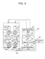
- Fig.2 illustrates a electrical makeup of the biped walking robot 10 shown in Fig.1.
- the biped walking robot 10 is provided with a gait forming part 24 to form gait data responsive to a demand for motion, and a walk controller 30 to control respective driving actions of drive means, namely the above-mentioned respective joint portions, that is, the joint driving motors 15L, 15R, to 20L, 20R based on the gait data.
- xyz coordinate system is used as that for the biped walking robot 10 with x direction as anteroposterior direction ( forward as +), with y direction as crosswise direction ( inner direction as +), and with z direction as vertical direction ( upper direction as +).
- the gait forming part 24 forms the gait data, responding to the targeted motion input from the outside.
- the gait data includes target angle path, target angle velocity, and target angle acceleration of respective joint portions 15L, 15R, to 20L, 20R required for the biped walking robot 10 to walk.
- the walk controller 30 comprises an angle measurement unit 31, a compensation part 32, a controlling part 33, and a motor controlling unit 34.
- the angle measurement unit 31 is to measure the angular positions of respective joint drive motors, that is, a state vector ⁇ about angle and angle velocity, and outputs to the compensation part 32, by inputting the angular information of respective joint drive motors from, for example, a rotary encoder or the like provided in the joint drive motors of respective joint portions 15L, 15R to 20L, 20R.
- the controlling part 33 forms a control signal of respective joint drive motors, that is, a torque vector ⁇ based on a vector ( ⁇ i - 0 0 ), by subtracting the angular vector ⁇ 0 at a robot's respective joint portions from the vector ⁇ i which is the gait data corrected by the compensation part 32.
- the motor controlling unit 34 controls respective driving actions of the joint drive motors according to the control signal (the torque vector ⁇ ) from the controlling part 33.
- the force sensor 23L comprises six force sensors 36a, 36b, 36c, 36d, 36e, and 36f, made up by horizontally divided, namely, three divisions in x direction and two divisions in y direction at an bottom of a sole plate 35 which is an bottom face of the foot portion 14L. Since each of the force sensors 36a, 36b, 36c, 36d, 36e, and 36f is of identical structure, explanation is made of the force sensor 36a, referring to Fig.4.
- the force sensor 36a is a 3-axis force sensor provided between a upper sole 37 and a lower 38, and detects a force received from a floor surface when the foot portion 14L lands on to a floor.
- the lower sole 38 is supported pivotally movably to the front and behind, the left and right, with the sensor axis of the force sensor 36a as the center, and is so designed as to be capable of landing in all directions by pivoting.
- the force sensors 23L and 23R are divided to six each, but the case should not be limited to this, and it may be at least four divisions at both sides of heel portions and both sides of toe portions of respective foot portions 14L, 14R, or may be divided to seven or more.
- each of force sensors 36a to 36f in the Figure arranged in a line at a sole, but the case should not be limited to this, and it may be arranged arbitrarily.
- a shock can be absorbed by each of 3-axis force sensors by landing to the floor from the heel portion of the foot portions 14L, 14R upon robot 10's walk.
- the above-mentioned force sensors 36a to 36f are 3-axis force sensors, and with two or more 3-axis force sensors, forces of hexaxial directional can be computed.
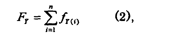
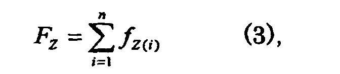
- Fig.5 explanation is made, referring to Fig.5, of computation of the forces of the hexaxial directional from 3-axis force sensors of n pieces in number in general.
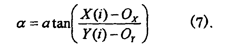
- 3-axis force sensors of n pieces S1, S2, S3, ---, Sn are arranged at a sole with respect to the origin O (Ox, Oy) of force measurement.
- the origin O of force measurement preferably better agrees, for example, to the drive coordinate system of a foot joint.
- a computation is conducted by a computation circuit set up inside the compensation part 32 based on the detected output of respective 3-axis force sensors 36a to 36f, thereby the force of hexaxial direction is detected.
- a horizontal floor reaction force F is expressed as a resultant force of a horizontal forces generated from a friction of the floor surface and a robot 10's sole, that is, the horizontal floor reaction force F is expressed as the resultant force of forces FX and FY in X and Y directions, and its vector FC and its magnitude
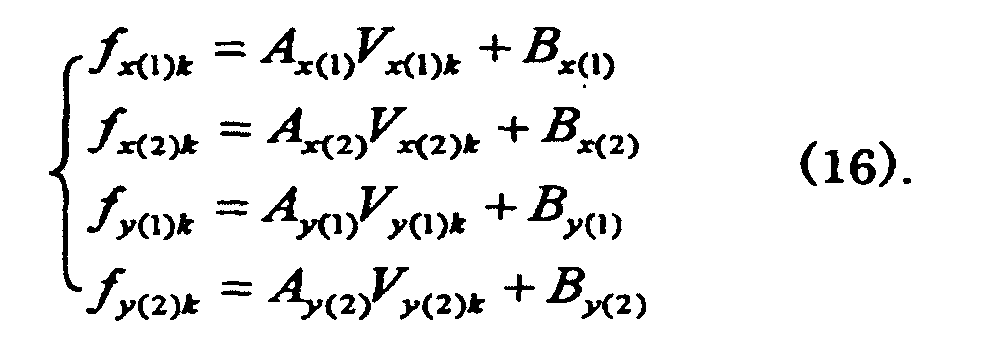
- each of 3-axis force sensors 36a to 36f has a fluctuation in the detected respective outputs, and the detected output fluctuates due to the surrounding temperature or the secular change. Therefore, the detected output from respective 3-axis force sensor 36a to 36f is automatically calibrated in the compensation part 32 by an auto calibration described below.
- Equation (13) a correction parameter for calibration can be calculated by conducting the measurements of n times.
- the dispersed and arranged 3-axis force sensors S1 to Sn choose two arbitrary 3-axis force sensors, for example, S1, S2 and generate a momentum m around z axis by utilizing a robot's upper body 11 or the leg portions 13L or 13R on the opposite side.
- calibration in XY axis direction can be conducted by calculating correction parameters A, B simultaneously in X and Y axis directions.
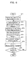
- the biped walking robot 10 in accordance with the embodiment of the present invention is constituted as described above, and its walking motion is conducted by the flowchart shown in Fig.6 as described below.
- the force sensors 23L, 23R attached to both foot portions 14L, 14R detect forces respectively, and output to the compensation part 32.
- the angle measurement unit 31 measures the state vector ⁇ of respective joint portions 16L, 16R to 20L, 20R, and outputs to the compensation part 32.
- the compensation part 32 computes a horizontal floor reaction force F based on the detected output from force sensors 23L, 23R.
- the compensation part 32 corrects the gait data based on this horizontal floor reaction force F and the state vector ⁇ of respective joint portions 16L, 16R to 20L, 20R from the angle measurement unit 31, and outputs the vector ⁇ i to the controlling part 33.
- the controlling part 33 subtracts a angle vector ⁇ 0 in a robot's respective joint portions from the vector ⁇ i, forms the control signal, that is, torque vector ⁇ of respective joint drive motors based on a vector ( ⁇ i- ⁇ 0), and outputs to the motor control unit 34.
- the motor control unit 34 drive-controls the joint drive motors of respective joint portions based on this torque vector ⁇ .
- the biped walking robot 10 conducts walking motions responsive to a demand for motion.
- the gait data for the biped walking robot 10, upon drive-controlling respective joint drive motors, is corrected based on the horizontal floor reaction force F from the force sensors 23L, 23R set at the soles of respective foot portions 14L, 14R by the compensation part 32, and a robot 10's stability is attained with this horizontal floor reaction force F as regulation by the vector ⁇ i being formed.
- a robot10's respective foot portions 14L, 14R land, for example, on a floor surface where soles slip, since the force sensors 23L, 23R set at the soles can detect the horizontal floor reaction force F, it is made possible to certainly conduct walking motions corresponding to the required motions.
- the force sensors 23L, 23R set at soles of respective foot portions 14L, 14R to detect the horizontal floor reaction force F is constituted with the 3-axis force sensors 36a to 36f provided to each of the divided six sections, the force applied to each 3-axis force sensor 36a to 36f provided at each divided section is dispersed, with each foot portion 14L, 14R being in the state of landing, thereby small and light-weighted sensors can be used as individual 3-axis force sensors 36a to 36f, and the cost can be reduced.
- each foot portion 14L, 14R is on the floor surface, a horizontal floor reaction force can be reliably detected. Accordingly, a robot's stability can be maintained, thereby reliable walk control becomes possible even when only a part of a sole of a robot's each foot portion contacts with the floor surface due, for example, to its roughness.
- the walk control is conducted with the horizontal floor reaction force F generated from the friction between the soles and the floor surface, thereby a robot 10's walk stability can be realized even in the road surface state where soles slip.
- the robot's stability can be maintained even in the road surface state where the foot stance is unstable, for example, such as wet floor, ice, mud, or the carpet of long hair, or in case that only a part of the sole of the robot's respective foot portion is in contact with floor surface due, for example, to its roughness, and a reliable walk control is possible, thereby an extremely superb biped walking mobile apparatus, its walk controller, and the strategy of walk control are provided.
Landscapes
- Engineering & Computer Science (AREA)
- Mechanical Engineering (AREA)
- Robotics (AREA)
- Chemical & Material Sciences (AREA)
- Combustion & Propulsion (AREA)
- Transportation (AREA)
- Human Computer Interaction (AREA)
- Manipulator (AREA)
Abstract
Description










Claims (13)
- A biped walking mobile apparatus comprising:characterized in that:a main body having at both sides of its lower part a pair of leg portions attached thereto so as to be each pivotally movable biaxially, each of the leg portions having a knee portion in its midway and a foot portion at its lower end, the foot portions being attached to their corresponding leg portions so as to be pivotally movable biaxially, drive means for pivotally moving respective leg, knee, and foot portions, a gait forming part for forming gait data including data for a target angular path, data for a targeted angular velocity and data for a targeted angular acceleration responsive to a demand for motion, and a walk controller for controlling respective driving actions of said drive means on the basis of said gait data,said walk controller comprises force sensors for detecting forces applied to soles of respective foot portions, and a compensation part for correcting said gait data from said gait forming part based on a horizontal floor reaction force among said forces detected by said force sensors.
- A biped walking mobile apparatus as set forth in Claim 1, characterized in that said main body is an upper body of a humanoid robot provided with a head portion and two hand portions.
- A biped walking mobile apparatus as set forth in Claim 1 or Claim 2, characterized in that said soles of respective foot portions are divided in plurality, and each divided section is provided with a force sensor.
- A biped walking mobile apparatus as set forth in either one of Claims 1 through 3, characterized in that said force sensor provided at said each divided section is a 3-axis force sensor, and said compensation part computes a hexaxial directional force based on the detected signals from respective force sensors.
- A biped walking mobile apparatus as set forth in Claim 4, characterized in that said compensation part automatically calibrates the detected signals from respective force sensors by auto calibration.
- A walk controller for a biped walking mobile apparatus which includes: a main body having at both sides of its lower part a pair of leg portions attached thereto so as to be each pivotally movable biaxially, each of the leg portions having a knee portion in its midway and a foot portion at its lower end, the foot portions being attached to their corresponding leg portions so as to be pivotally movable biaxially, drive means for pivotally moving respective leg, knee, and foot portions, and a gait forming part for forming gait data including data for a target angular path, data for a targeted angular velocity and data for a targeted angular acceleration responsive to a demand for motion, whereby said walk controller controls respective driving actions of said drive means on the basis of said gait data,
characterized in that:said walk controller comprises force sensors for detecting forces applied to soles of respective foot portions, and a compensation part for correcting said gait data from said gait forming part based on a horizontal floor reaction force among said forces detected by said force sensors. - A walk controller for a biped walking mobile apparatus as set forth in Claim 6, characterized in that said soles of respective foot portions are divided in plurality, and each divided section is provided with a force sensor.
- A walk controller for a biped walking mobile apparatus as set forth in Claim 7, characterized in that said force sensor provided at said each divided section is a 3-axis force sensor, and said compensation part computes a hexaxial directional force based on the detected signals from respective force sensors.
- A walk controller for a biped walking mobile apparatus as set forth in Claim 8, characterized in that said compensation part automatically calibrates the detected signals from respective force sensors by auto calibration.
- A walk controlling strategy for a biped walking mobile apparatus which includes: a main body having at both sides of its lower part a pair of leg portions attached thereto so as to be each pivotally movable biaxially, each of the leg portions having a knee portion in its midway and a foot portion at its lower end, the foot portions being attached to their corresponding leg portions so as to be pivotally movable biaxially, drive means for pivotally moving respective leg, knee, and foot portions, and a gait forming part for forming gait data including data for a target angular path, data for a targeted angular velocity and data for a targeted angular acceleration responsive to a demand for motion, whereby the strategy controls respective driving actions of said drive means on the basis of said gait data,
characterized in that:said walk controlling strategy includes, on the occasion of correction of said gait data, a first step for detecting forces applied to soles of respective foot portions by force sensors, and a second step for correcting said gait data from said gait forming part based on a horizontal floor reaction force among said forces detected by said force sensors. - A walk controlling strategy for a biped walking mobile apparatus as set forth in Claim 10, characterized in that said soles of respective foot portions are divided in plurality, and each divided section is provided with a force sensor.
- A walk controlling strategy for a biped walking mobile apparatus as set forth in Claim 11, characterized in that said force sensor provided at said each divided section is a 3-axis force sensor, and said compensation part computes a hexaxial directional force based on the detected signals from respective force sensors.
- A walk controlling strategy for a biped walking mobile apparatus as set forth in Claim 12, characterized in that said compensation part automatically calibrates the detected signals from respective force sensors by auto calibration.
Applications Claiming Priority (3)
| Application Number | Priority Date | Filing Date | Title |
|---|---|---|---|
| JP2001386693A JP3574951B2 (en) | 2001-12-19 | 2001-12-19 | Biped walking type moving device, its walking control device and walking control method |
| JP2001386693 | 2001-12-19 | ||
| PCT/JP2002/012057 WO2003051582A1 (en) | 2001-12-19 | 2002-11-19 | Bipedal walking type moving device, and walking control device and walking control method therefor |
Publications (3)
| Publication Number | Publication Date |
|---|---|
| EP1464451A1 true EP1464451A1 (en) | 2004-10-06 |
| EP1464451A4 EP1464451A4 (en) | 2008-04-09 |
| EP1464451B1 EP1464451B1 (en) | 2010-07-14 |
Family
ID=19187960
Family Applications (1)
| Application Number | Title | Priority Date | Filing Date |
|---|---|---|---|
| EP02805016A Expired - Lifetime EP1464451B1 (en) | 2001-12-19 | 2002-11-19 | Bipedal walking type moving device; and walking control device and walking control method therefor |
Country Status (8)
| Country | Link |
|---|---|
| US (1) | US20050016778A1 (en) |
| EP (1) | EP1464451B1 (en) |
| JP (1) | JP3574951B2 (en) |
| KR (1) | KR100559408B1 (en) |
| CN (1) | CN100344415C (en) |
| DE (1) | DE60237038D1 (en) |
| TW (1) | TW575482B (en) |
| WO (1) | WO2003051582A1 (en) |
Cited By (1)
| Publication number | Priority date | Publication date | Assignee | Title |
|---|---|---|---|---|
| DE102013218853B4 (en) | 2012-12-27 | 2019-09-19 | Hyundai Motor Company | Method and system for controlling the gait of a robot |
Families Citing this family (20)
| Publication number | Priority date | Publication date | Assignee | Title |
|---|---|---|---|---|
| JP4649913B2 (en) * | 2003-09-19 | 2011-03-16 | ソニー株式会社 | Robot apparatus and movement control method of robot apparatus |
| KR100571829B1 (en) * | 2004-02-06 | 2006-04-17 | 삼성전자주식회사 | Structure, foot structure and robot |
| KR100597558B1 (en) * | 2004-11-12 | 2006-07-06 | 학교법인 명지학원 | GMP detection system using strain gauge and its detection method |
| JP4506512B2 (en) * | 2005-03-07 | 2010-07-21 | トヨタ自動車株式会社 | Offset adjustment system and offset adjustment method for walking robot with supporting legs |
| JP4008465B2 (en) * | 2005-09-02 | 2007-11-14 | 本田技研工業株式会社 | Motion induction device |
| JP4877668B2 (en) * | 2006-06-07 | 2012-02-15 | 有限会社ケイテックシステム | Standing balance measuring device |
| US7582994B2 (en) * | 2007-06-20 | 2009-09-01 | Honda Motor Co., Ltd. | Electric actuator |
| KR100920224B1 (en) | 2007-12-11 | 2009-10-05 | 경상대학교산학협력단 | Intelligent foot of humanoid robot |
| US8423190B1 (en) | 2009-06-11 | 2013-04-16 | Kabushiki Kaisha Yaskawa Denki | Manipulator system |
| KR101025512B1 (en) | 2009-06-16 | 2011-04-04 | 경상대학교산학협력단 | Adaptive walk assistance device for increased walking stability |
| KR101097040B1 (en) | 2009-09-16 | 2011-12-22 | (주)동부로봇 | Unusal walking Calibration Method of Walking Robot |
| US9331186B2 (en) | 2009-12-21 | 2016-05-03 | Nxp B.V. | Semiconductor device with multilayer contact and method of manufacturing the same |
| US8805584B2 (en) * | 2011-11-22 | 2014-08-12 | Disney Enterprises, Inc | Kinematic and dynamic calibration methods for legged robots with force-controlled joints |
| KR101262978B1 (en) * | 2011-12-05 | 2013-05-08 | 현대자동차주식회사 | Module and method for measuring repulsive force for walking robot |
| KR101428325B1 (en) | 2012-12-27 | 2014-08-07 | 현대자동차주식회사 | Robot foot apparatus |
| CN105446345A (en) * | 2015-07-02 | 2016-03-30 | 浙江大学 | Control system of humanoid biped robot |
| CN107203212A (en) * | 2017-07-04 | 2017-09-26 | 西北工业大学 | Realize the small-sized humanoid robot and its control method of omnidirectional's walking |
| CN109333506B (en) * | 2018-10-23 | 2021-12-17 | 广东工业大学 | Humanoid intelligent robot system |
| JP7046110B2 (en) * | 2020-02-21 | 2022-04-01 | 株式会社ソニー・インタラクティブエンタテインメント | Sensor control device, sensor control method and program |
| WO2023248697A1 (en) * | 2022-06-24 | 2023-12-28 | ソニーグループ株式会社 | Information processing device, information processing method, and program |
Family Cites Families (19)
| Publication number | Priority date | Publication date | Assignee | Title |
|---|---|---|---|---|
| JPS60221288A (en) * | 1984-04-13 | 1985-11-05 | 株式会社 富士電機総合研究所 | Pressure sensing recognizing controller |
| US5263375A (en) * | 1987-09-18 | 1993-11-23 | Wacoh Corporation | Contact detector using resistance elements and its application |
| JP2520019B2 (en) * | 1989-06-29 | 1996-07-31 | 本田技研工業株式会社 | Drive controller for legged mobile robot |
| JP2826858B2 (en) * | 1989-12-14 | 1998-11-18 | 本田技研工業株式会社 | Leg structure of a legged walking robot |
| US5255753A (en) * | 1989-12-14 | 1993-10-26 | Honda Giken Kogyo Kabushiki Kaisha | Foot structure for legged walking robot |
| US5455497A (en) * | 1992-04-20 | 1995-10-03 | Honda Giken Kogyo Kabushiki Kaisha | Legged mobile robot and a system for controlling the same |
| JPH07121214A (en) * | 1993-10-25 | 1995-05-12 | Fanuc Ltd | Robot measurement sensor device, calibration method and measurement method using the device |
| JP3429048B2 (en) * | 1993-12-30 | 2003-07-22 | 本田技研工業株式会社 | Walking control device for legged mobile robot |
| JP3361386B2 (en) * | 1994-07-04 | 2003-01-07 | 日鍛バルブ株式会社 | Camshaft phase change device |
| US5608172A (en) * | 1995-03-16 | 1997-03-04 | Texas Instruments Incorporated | Die bond touch down detector |
| JPH09212203A (en) * | 1995-11-30 | 1997-08-15 | Sony Corp | Robot controller |
| JP3626303B2 (en) * | 1996-12-18 | 2005-03-09 | 本田技研工業株式会社 | Foot ground contact position detector for legged mobile robot |
| JP3400377B2 (en) * | 1999-03-10 | 2003-04-28 | 富士通株式会社 | Foot sensor and humanoid robot having the same |
| US6868746B1 (en) * | 1999-05-07 | 2005-03-22 | Northwestern University | Method and apparatus for force sensors |
| JP4213310B2 (en) * | 1999-08-30 | 2009-01-21 | 本田技研工業株式会社 | Biped legged mobile robot |
| JP4480843B2 (en) * | 2000-04-03 | 2010-06-16 | ソニー株式会社 | Legged mobile robot, control method therefor, and relative movement measurement sensor for legged mobile robot |
| AU2002224042A1 (en) * | 2000-11-17 | 2002-05-27 | Honda Giken Kogyo Kabushiki Kaisha | Gait pattern generating device for legged mobile robot |
| US6989677B2 (en) * | 2000-11-30 | 2006-01-24 | Nitta Corporation | Capacitance type sensor |
| JP3574952B2 (en) * | 2002-02-18 | 2004-10-06 | 独立行政法人 科学技術振興機構 | Bipod walking type moving device and its walking control device |
-
2001
- 2001-12-19 JP JP2001386693A patent/JP3574951B2/en not_active Expired - Fee Related
-
2002
- 2002-11-19 DE DE60237038T patent/DE60237038D1/en not_active Expired - Lifetime
- 2002-11-19 WO PCT/JP2002/012057 patent/WO2003051582A1/en not_active Ceased
- 2002-11-19 CN CNB028256751A patent/CN100344415C/en not_active Expired - Fee Related
- 2002-11-19 KR KR1020047009232A patent/KR100559408B1/en not_active Expired - Fee Related
- 2002-11-19 EP EP02805016A patent/EP1464451B1/en not_active Expired - Lifetime
- 2002-11-19 US US10/499,306 patent/US20050016778A1/en not_active Abandoned
- 2002-11-20 TW TW091133794A patent/TW575482B/en not_active IP Right Cessation
Cited By (1)
| Publication number | Priority date | Publication date | Assignee | Title |
|---|---|---|---|---|
| DE102013218853B4 (en) | 2012-12-27 | 2019-09-19 | Hyundai Motor Company | Method and system for controlling the gait of a robot |
Also Published As
| Publication number | Publication date |
|---|---|
| JP3574951B2 (en) | 2004-10-06 |
| TW200301182A (en) | 2003-07-01 |
| EP1464451A4 (en) | 2008-04-09 |
| TW575482B (en) | 2004-02-11 |
| KR100559408B1 (en) | 2006-03-10 |
| JP2003181781A (en) | 2003-07-02 |
| EP1464451B1 (en) | 2010-07-14 |
| CN1606488A (en) | 2005-04-13 |
| WO2003051582A1 (en) | 2003-06-26 |
| CN100344415C (en) | 2007-10-24 |
| KR20040071204A (en) | 2004-08-11 |
| DE60237038D1 (en) | 2010-08-26 |
| US20050016778A1 (en) | 2005-01-27 |
Similar Documents
| Publication | Publication Date | Title |
|---|---|---|
| EP1464451B1 (en) | Bipedal walking type moving device; and walking control device and walking control method therefor | |
| EP1477283A1 (en) | Two-legged walking locomotion apparatus and its walking controller | |
| EP1721711B1 (en) | Gait generator of mobile robot | |
| EP1510302B1 (en) | Attitude control device of mobile robot | |
| EP1649983B1 (en) | Gait generation device for legged mobile robot | |
| EP1707324A1 (en) | Gait generator for mobile robot | |
| US20060197485A1 (en) | Method of assuming acting point of floor reaction force to biped walking mobile body and method of assuming joint moment of biped walking mobile body | |
| EP1844908B1 (en) | Legged mobile robot and control program for the robot | |
| EP1842628B1 (en) | Legged mobile robot | |
| EP1552909A1 (en) | Walking type moving device and walking control device therefor and walking control method | |
| EP1733852B1 (en) | Gait generator for mobile robot | |
| EP1736286B1 (en) | Gait producing device for moving robot | |
| JP3569768B2 (en) | Biped walking device | |
| JP3760198B2 (en) | Walking movement apparatus, walking control apparatus and walking control method therefor | |
| JPH05253867A (en) | Walk control device for leg type moving robot |
Legal Events
| Date | Code | Title | Description |
|---|---|---|---|
| PUAI | Public reference made under article 153(3) epc to a published international application that has entered the european phase |
Free format text: ORIGINAL CODE: 0009012 |
|
| 17P | Request for examination filed |
Effective date: 20040706 |
|
| AK | Designated contracting states |
Kind code of ref document: A1 Designated state(s): AT BE BG CH CY CZ DE DK EE ES FI FR GB GR IE IT LI LU MC NL PT SE SK TR |
|
| A4 | Supplementary search report drawn up and despatched |
Effective date: 20080311 |
|
| 17Q | First examination report despatched |
Effective date: 20080711 |
|
| GRAP | Despatch of communication of intention to grant a patent |
Free format text: ORIGINAL CODE: EPIDOSNIGR1 |
|
| GRAS | Grant fee paid |
Free format text: ORIGINAL CODE: EPIDOSNIGR3 |
|
| GRAA | (expected) grant |
Free format text: ORIGINAL CODE: 0009210 |
|
| AK | Designated contracting states |
Kind code of ref document: B1 Designated state(s): DE FR GB NL |
|
| REG | Reference to a national code |
Ref country code: GB Ref legal event code: FG4D |
|
| REF | Corresponds to: |
Ref document number: 60237038 Country of ref document: DE Date of ref document: 20100826 Kind code of ref document: P |
|
| REG | Reference to a national code |
Ref country code: NL Ref legal event code: VDEP Effective date: 20100714 |
|
| PG25 | Lapsed in a contracting state [announced via postgrant information from national office to epo] |
Ref country code: NL Free format text: LAPSE BECAUSE OF FAILURE TO SUBMIT A TRANSLATION OF THE DESCRIPTION OR TO PAY THE FEE WITHIN THE PRESCRIBED TIME-LIMIT Effective date: 20100714 |
|
| PLBE | No opposition filed within time limit |
Free format text: ORIGINAL CODE: 0009261 |
|
| STAA | Information on the status of an ep patent application or granted ep patent |
Free format text: STATUS: NO OPPOSITION FILED WITHIN TIME LIMIT |
|
| 26N | No opposition filed |
Effective date: 20110415 |
|
| GBPC | Gb: european patent ceased through non-payment of renewal fee |
Effective date: 20101119 |
|
| REG | Reference to a national code |
Ref country code: DE Ref legal event code: R097 Ref document number: 60237038 Country of ref document: DE Effective date: 20110415 |
|
| REG | Reference to a national code |
Ref country code: FR Ref legal event code: ST Effective date: 20110801 |
|
| REG | Reference to a national code |
Ref country code: DE Ref legal event code: R119 Ref document number: 60237038 Country of ref document: DE Effective date: 20110601 Ref country code: DE Ref legal event code: R119 Ref document number: 60237038 Country of ref document: DE Effective date: 20110531 |
|
| PG25 | Lapsed in a contracting state [announced via postgrant information from national office to epo] |
Ref country code: FR Free format text: LAPSE BECAUSE OF NON-PAYMENT OF DUE FEES Effective date: 20101130 |
|
| PG25 | Lapsed in a contracting state [announced via postgrant information from national office to epo] |
Ref country code: GB Free format text: LAPSE BECAUSE OF NON-PAYMENT OF DUE FEES Effective date: 20101119 |
|
| PG25 | Lapsed in a contracting state [announced via postgrant information from national office to epo] |
Ref country code: DE Free format text: LAPSE BECAUSE OF NON-PAYMENT OF DUE FEES Effective date: 20110531 |