EP1464286A1 - Apparatus and method for x-ray computed tomography - Google Patents
Apparatus and method for x-ray computed tomography Download PDFInfo
- Publication number
- EP1464286A1 EP1464286A1 EP04251467A EP04251467A EP1464286A1 EP 1464286 A1 EP1464286 A1 EP 1464286A1 EP 04251467 A EP04251467 A EP 04251467A EP 04251467 A EP04251467 A EP 04251467A EP 1464286 A1 EP1464286 A1 EP 1464286A1
- Authority
- EP
- European Patent Office
- Prior art keywords
- range
- ray computed
- reconstruction
- reconstruction range
- scan
- Prior art date
- Legal status (The legal status is an assumption and is not a legal conclusion. Google has not performed a legal analysis and makes no representation as to the accuracy of the status listed.)
- Granted
Links
Images




Classifications
-
- A—HUMAN NECESSITIES
- A61—MEDICAL OR VETERINARY SCIENCE; HYGIENE
- A61B—DIAGNOSIS; SURGERY; IDENTIFICATION
- A61B6/00—Apparatus or devices for radiation diagnosis; Apparatus or devices for radiation diagnosis combined with radiation therapy equipment
- A61B6/46—Arrangements for interfacing with the operator or the patient
- A61B6/467—Arrangements for interfacing with the operator or the patient characterised by special input means
- A61B6/469—Arrangements for interfacing with the operator or the patient characterised by special input means for selecting a region of interest [ROI]
-
- A—HUMAN NECESSITIES
- A61—MEDICAL OR VETERINARY SCIENCE; HYGIENE
- A61B—DIAGNOSIS; SURGERY; IDENTIFICATION
- A61B6/00—Apparatus or devices for radiation diagnosis; Apparatus or devices for radiation diagnosis combined with radiation therapy equipment
- A61B6/02—Arrangements for diagnosis sequentially in different planes; Stereoscopic radiation diagnosis
- A61B6/027—Arrangements for diagnosis sequentially in different planes; Stereoscopic radiation diagnosis characterised by the use of a particular data acquisition trajectory, e.g. helical or spiral
-
- A—HUMAN NECESSITIES
- A61—MEDICAL OR VETERINARY SCIENCE; HYGIENE
- A61B—DIAGNOSIS; SURGERY; IDENTIFICATION
- A61B6/00—Apparatus or devices for radiation diagnosis; Apparatus or devices for radiation diagnosis combined with radiation therapy equipment
- A61B6/02—Arrangements for diagnosis sequentially in different planes; Stereoscopic radiation diagnosis
- A61B6/03—Computed tomography [CT]
- A61B6/032—Transmission computed tomography [CT]
-
- G—PHYSICS
- G06—COMPUTING OR CALCULATING; COUNTING
- G06T—IMAGE DATA PROCESSING OR GENERATION, IN GENERAL
- G06T12/00—Tomographic reconstruction from projections
-
- G—PHYSICS
- G06—COMPUTING OR CALCULATING; COUNTING
- G06T—IMAGE DATA PROCESSING OR GENERATION, IN GENERAL
- G06T12/00—Tomographic reconstruction from projections
- G06T12/10—Image preprocessing, e.g. calibration, positioning of sources or scatter correction
-
- Y—GENERAL TAGGING OF NEW TECHNOLOGICAL DEVELOPMENTS; GENERAL TAGGING OF CROSS-SECTIONAL TECHNOLOGIES SPANNING OVER SEVERAL SECTIONS OF THE IPC; TECHNICAL SUBJECTS COVERED BY FORMER USPC CROSS-REFERENCE ART COLLECTIONS [XRACs] AND DIGESTS
- Y10—TECHNICAL SUBJECTS COVERED BY FORMER USPC
- Y10S—TECHNICAL SUBJECTS COVERED BY FORMER USPC CROSS-REFERENCE ART COLLECTIONS [XRACs] AND DIGESTS
- Y10S378/00—X-ray or gamma ray systems or devices
- Y10S378/901—Computer tomography program or processor
Definitions
- the present invention relates to apparatus and method for the X-ray computed tomography.
- the X-ray computed tomographic apparatus also referred to as the CT scanner
- the X-ray computed tomographic apparatus provides information of the subject in the form of images on the basis of the intensity of X-rays having passed through the subject, and plays an important role in many medical practices including diagnosis of illness, treatment and operation planning, etc.
- the advent of helical scan has made it possible to achieve wide-range data acquisition in a short time.
- the patient throughput has become one of critical issues associated with such achievement. Due to ultrafast scans as well as weight saving of X-ray tubes, widespread use of helical scan, increasing number of detector arrays, and enhancement of detection sensitivity in recent years, the patient throughput is influenced more by a time needed for pre-scan setting of the subject than the scan time. The subject lies on his back on the tabletop of the diagnostic table and fine adjusts the body position according to radiologist's instructions. However, only a limited time is allowed for fine adjustment of the body position. Hence, as is shown in FIG.
- An object of the invention is therefore to address an event such that scans are performed while the body axis of the subject is tilted with respect to the center line (Z-axis, the rotational axis of the X-ray tube) of the scan range.
- An X-ray computed tomographic apparatus of the invention includes: a display portion to display, on a screen, a scanogram related to a subject together with a quadrilateral frame line specifying a reconstruction range; an input portion to input a command to transform the frame line specifying the reconstruction range to a parallelogram or rotate the frame line specifying the reconstruction range; a gantry to perform scanning in a scan range corresponding to the reconstruction range; and a reconstruction portion to reconstruct image data related to plural slices, parallel to one another and included in the reconstruction range, slice-by-slice on the basis of projection data acquired by the scanning.
- the X-ray computed tomographic apparatus includes various types, such as a rotate/rotate type in which a unit comprising the X-ray tube and the radiation detector rotates about the subject, and a stationary/rotate type in which a number of detection elements are aligned in a ring-shaped array and the X-ray tube alone rotates about the subject, and the invention is applicable to any type.
- a rotate/rotate type in which a unit comprising the X-ray tube and the radiation detector rotates about the subject
- a stationary/rotate type in which a number of detection elements are aligned in a ring-shaped array and the X-ray tube alone rotates about the subject
- X-ray detection elements adopting either scheme can be used, and herein, those adopting the former indirect conversion scheme will be described.
- a so-called multi-tube type X-ray computed tomographic apparatus in which plural pairs of an X-ray tube and an X-ray detector are mounted to a rotational ring, has become commercially available recently, and the peripheral techniques are also under development.
- the invention is applicable to either a conventional single-tube type X-ray computed tomographic apparatus or a multi-tube type X-ray computed tomographic apparatus.
- a single-tube type X-ray computed tomographic apparatus will be described.
- FIG. 2 shows the configuration of the X-ray computed tomographic apparatus according to this embodiment.
- the X-ray computed tomographic apparatus includes a gantry 1 configured to acquire projection data related to the subject.
- the gantry 1 includes an X-ray tube 10 and an X-ray detector 23. Both the X-ray tube 10 and the X-ray detector 23 are mounted to a ring-shaped rotational frame 12, which is driven to rotate about the Z-axis by a gantry driving device 25.
- the rotational frame 12 is provided with an aperture at the center thereof, and the subject P laid on the tabletop 2a of the diagnostic table 2 is inserted into the aperture.
- a slit 22 used to vary the irradiation width of X-rays depending on the slice thickness is placed between the X-ray tube 10 and the aperture.
- a tube voltage from a high voltage transformer assembly 21 is applied between the cathode and the anode of the X-ray tube 10, while a filament current from the high voltage transformer assembly 21 is supplied to the filament of the X-ray tube 10.
- X-rays are generated by the application of the tube voltage and the supply of the filament current.
- the X-ray detector 23 includes plural X-ray detection elements 100 each having, for example, a 0.5 mm ⁇ 0.5 mm tetragonal light-reception surface.
- the X-ray detector 23 includes plural X-ray detection elements 100 each having, for example, a 0.5 mm ⁇ 0.5 mm tetragonal light-reception surface.
- 916 X-ray detection elements 100 are aligned in an array along the channel direction.
- arrays of FIG. 3A are provided, for example, in 40 rows in parallel along the slice direction.
- the detector of FIG. 3A is referred to as the single-slice type, and the detector of FIG. 3B is referred to as the multi-slice type.
- the X-ray detector 23 can be of either type.
- a data acquisition device 24 generally referred to as a DAS (data acquisition system) converts a signal in each channel outputted from the detector 23 to a voltage signal, amplifies the voltage signal, and converts the amplified voltage signal to a digital signal.
- Data thus obtained is supplied to a computer unit 3 installed at the outside of the gantry.
- a pre-processing unit 34 of the computer unit 3 performs compensation processing, such as sensitivity compensation, on the raw data outputted from the data acquisition device 24, and outputs projection data.
- the projection data is then sent to and stored in a data storage device 35 of the computer system 3.
- the computer system 3 comprises a system controller 29, an input device 39 provided with a keyboard, a mouse, etc., a display 38, a scan controller 30, a reconstruction unit 36, and a scan procedure system 42 in addition to the aforementioned pre-processing unit 34 and the storage device 35.
- the reconstruction unit 36 is able to selectively perform the reconstruction processing according to either of the followings: the typical fan-beam reconstruction method (also referred to as the fan-beam convolution back projection method); and a reconstruction method in a case where projection rays cross with the reconstruction plane like a cone beam, other than the helical interpolation that can be used together with the fan-beam reconstruction method in finding projection data on the reconstruction plane through interpolation from projection data of, for example, two rotations, the method including the Feldkamp method, known as an approximate image reconstruction method, by which convolution is performed by deeming the beam as a fan projection beam on the assumption that the cone angle is small and back projection is performed along rays at the time of scanning, and the cone-beam reconstruction method, known as a method capable of suppressing cone-angle induced errors compared with the Feldkamp method, by which projection data is compensated in response to the angle of rays with respect to the reconstruction plane.
- the typical fan-beam reconstruction method also referred to as the fan-beam con
- the scan procedure system 42 is provided to assist the operator in a work of determining the scan procedure, and constructs a scan procedure screen used to set scan conditions, such as a helical pitch (HP) indicating a distance the tabletop moves while the X-ray tube 10 rotates once as shown in FIG. 4, and a scan speed (SS) indicating a time needed for the X-ray tube 10 to rotate once.
- a scan procedure screen used to set scan conditions, such as a helical pitch (HP) indicating a distance the tabletop moves while the X-ray tube 10 rotates once as shown in FIG. 4, and a scan speed (SS) indicating a time needed for the X-ray tube 10 to rotate once.
- HP helical pitch
- SS scan speed
- FIG. 5 shows an example of the scan procedure screen.
- the scan procedure screen includes patient information, gantry information, and detailed information of the scan conditions at the bottom of the screen as well as a scanogram image 99.
- the scanogram image 99 is displayed in an orientation such that the Z-axis (the center of rotation) thereof is parallel to the vertical direction (possibly, the horizontal direction in some cases) of the screen.
- the scanogram image 99 is displayed on the screen as being tilted with respect to the vertical direction of the screen as well.
- the scan conditions include the activation (distinction between the manual trigger and the automatic trigger to start the scan), scan start time (start time), start position of helical scan, a pause between scans, end position of helical scan, scan mode (distinction among single-slice/multi-slice/helical), start position of scan, end position of scan, tube voltage kV, tube current mA, scan speed (time in parentheses indicates a time needed for the entire scans), the number of slices (the number of arrays used), helical pitch, reconstruction mode, and FOV (width of reconstruction range).
- a quadrilateral frame line 101 specifying the reconstruction range is displayed on the scanogram image 99.
- a frame line, generally in a dotted line, specifying the scan range corresponding to the reconstruction range is displayed together with the frame line 101 specifying the reconstruction range in some cases.
- the quadrilateral frame line 101 specifying the reconstruction range is initially provided as an oblong with its center line 109 being parallel to the Z-axis (central axis of rotation).
- rhombic icons 102 for scaling up/down the range vertically and rhombic icons 103 for scaling up/down the range horizontally are displayed at the four corners of the frame line 101 specifying the reconstruction range, so that the operator is able to scale up/down the reconstruction range as needed by moving the pointer 104 to any of the icons 102 and 103 and dragging the pointer 104 with the use of, for example, the mouse of the input device 39. Also, the operator is able to move the reconstruction range in parallel vertically and/or horizontally by moving the pointer 104 on the frame line 101 and dragging the pointer 104 with the use of, for example, the mouse of the input device 39.
- transformation icons 105 and 106 and rotation icons 107 and 108 are superposed transformation icons 105 and 106 and rotation icons 107 and 108.
- a transformation command is inputted with a click on the transformation icon 105.
- the frame line 101 specifying the reconstruction range is transformed to a parallelogram.
- a degree of transformation that is, a tilt of the center line 109 with respect to the vertical direction of the screen, is determined, for example, by the number of clicks. For instance, a tilt of 2.5° is given with one click.
- the frame line 101 specifying the reconstruction range is transformed in an opposite direction to the direction of FIG. 6.
- a degree of transformation is also determined by the number of clicks.
- a rotation command is inputted with a click on the rotation icon 107.
- the frame line 101 specifying the reconstruction range is rotated about its center.
- a degree of rotation that is, a tilt of the center line 109 with respect to the vertical direction of the screen, is determined, for example, by the number of clicks. For instance, a rotation by 2.5° is given with one click.
- the frame line 101 specifying the reconstruction range is rotated in a direction opposite to the direction of FIG. 7.
- a degree of rotation is also determined by the number of clicks. Basically, transformation and rotation are performed alternatively.
- the scanogram image 99 is displayed in an orientation such that the Z-axis (center of rotation) thereof is parallel to the vertical direction of the screen.
- the tilt is reflected on the scanogram image 99 on the screen as are shown in FIG. 6 and FIG. 7.
- the operator thus drags and moves the frame line 101 specifying the reconstruction range in parallel and clicks either the transformation icon 105 in the forward direction or the transformation icon 106 in the backward direction as many times as necessary, so that the center line 109 of the frame line 101 specifying the reconstruction range becomes parallel to and agrees as much as possible with the body axis of the subject on the tilted scanogram image 99.
- the operator drags and moves the frame line 101 specifying the reconstruction range in parallel and clicks either the rotation icon 107 in the forward direction or the rotation icon 108 in the backward direction as many times as necessary, so that the center line 109 of the frame line 101 specifying the reconstruction range becomes parallel to and agrees as much as possible with the body axis of the subject assumed on the tilted scanogram image 99.
- the scan procedure system 42 determines, as is shown in FIG. 8A, the reconstruction range 111 to correspond to the frame line 101, and determines the scan range 112 to correspond to the reconstruction range 111.
- the scan range 112 is set to the shape of a cylindrical column whose longitudinal cross section is an oblong having the Z-axis (axis of rotation) at the center and covering the reconstruction range 111.
- the reconstruction unit 36 extracts projection data corresponding to respective slices from projection data acquired by scans, and reconstructs image data on the basis of the projection data thus extracted.
- Widths of the respective slices are set according to the horizontal width of the frame line 101 specifying the reconstruction range, and the centers of the respective slices are set on the center line 109 of the frame line 101 specifying the reconstruction range. Because the center line 109 of the reconstruction range is set with a tilt with respect to the center line of the scan range, the horizontal positions of the respective slices, that is, a distance from the center line of the scan range to the center of each slice, vary from slice to slice. However, the centers of the respective slices are all placed on the body axis of the subject.
- the center of the slice can be set for each slice in response to the tilted body position of the subject in the manner descried above, even when scans are performed while the body axis of the subject is titled with respect to the Z-axis, the body axis of the subject can be positioned on almost the center of the image as shown in FIG. 8C. This eliminates offset between the position on the image and the position on the subject, which makes observation quite easy. Also, by converting a horizontal distance of the subject to an actual distance on the basis of the tilt of the frame line 101, it is possible to reduce errors in measurement of a distance or a volume.
- the scan procedure system 42 determines, as is shown in FIG. 9A, the reconstruction range 111 corresponding to the frame line 101 together with the scan range 112.
- the scan range 112 is set to the shape of a cylindrical column whose longitudinal cross section is an oblong having the Z-axis (axis of rotation) at the center and covering the reconstruction range 111.
- the scan range 112 can be selected from the range shown in FIG. 10A and the range shown in FIG. 10B wider than the one shown in FIG. 10A.
- projection data at the slice position is generated through interpolation from projection data of two, preceding and following rotations.
- the helical reconstruction needs projection data that covers a wider range 113, which is wider than the outermost slice within the reconstruction range 111 to the outside by at least one rotation.
- FIG. 10B shows an example when the scan range 112 is set to acquire the entire projection data of this wider range 113.
- FIG. 10A shows an example of a narrow scan range 112, in which part of projection data shaded by diagonal lines is replenished through extrapolative interpolation. The operator may make a selection between these two types, or the selection may be made automatically depending on the various conditions of the region to be imaged.
- the reconstruction unit 36 reconstructs image data by either the cone-beam reconstruction method or the tilt reconstruction method for each of plural slices (reconstruction planes) orthogonal to the center line 109 of the reconstruction range rotated in response to a tilt of the body axis of the subject, on the basis of the projection data acquired by scans.
- the pixel value of each pixel within the slice tilted with respect to the central axis of the scan range is computed as a filter integral value of projection data of plural X-ray paths that cross with the each pixel diagonally.
- each slice is set according to the width of the frame line 101 specifying the reconstruction range, and the center of each slice is set on the center line 109 of the frame line 101 specifying the reconstruction range. Because the center line 109 of the reconstruction range is set with a tilt with respect to the center line of the scan range, the horizontal positions of the respective slices, that is, a distance from the center line of the scan range to the center of each slice, vary from slice to slice.
- the center of the slice can be set for each slice in response to the titled body position of the subject in the manner described above, even when scans are performed while the body axis of the subject is tilted with respect to the Z-axis, the body axis of the subject can be positioned on almost the center of the image as is shown in FIG. 9C. Moreover, in this example, an image of a plane orthogonal to the body axis of the subject can be obtained, which reduces errors in horizontal distance associated with a tilt of the body axis with respect to the Z-axis. In short, it is possible to substantially eliminate a state where the body axis of the subject is tilted with respect to the Z-axis. Because errors in distance can be eliminated not only vertically but also horizontally, errors can be reduced in measurement of a distance or a volume; moreover, MPR (multi-planar reconstruction) processing or 3-D processing can be performed directly without the need for special compensation processing.
- MPR multi-planar reconstruction
- the invention can be applied to, for example, PET (Positron Emission computed Tomography), as an image diagnosis apparatus of a type that reconstructs a planar image on the basis of the subject's data acquired in many directions, as with the X-ray computed tomographic apparatus.
- PET Positron Emission computed Tomography
Landscapes
- Engineering & Computer Science (AREA)
- Health & Medical Sciences (AREA)
- Life Sciences & Earth Sciences (AREA)
- Medical Informatics (AREA)
- Physics & Mathematics (AREA)
- Radiology & Medical Imaging (AREA)
- Heart & Thoracic Surgery (AREA)
- High Energy & Nuclear Physics (AREA)
- Theoretical Computer Science (AREA)
- Nuclear Medicine, Radiotherapy & Molecular Imaging (AREA)
- Optics & Photonics (AREA)
- Pathology (AREA)
- Veterinary Medicine (AREA)
- Biomedical Technology (AREA)
- Biophysics (AREA)
- Molecular Biology (AREA)
- Surgery (AREA)
- Animal Behavior & Ethology (AREA)
- General Health & Medical Sciences (AREA)
- Public Health (AREA)
- General Physics & Mathematics (AREA)
- Human Computer Interaction (AREA)
- Pulmonology (AREA)
- Apparatus For Radiation Diagnosis (AREA)
Abstract

Description
- The present invention relates to apparatus and method for the X-ray computed tomography.
- The X-ray computed tomographic apparatus (also referred to as the CT scanner) provides information of the subject in the form of images on the basis of the intensity of X-rays having passed through the subject, and plays an important role in many medical practices including diagnosis of illness, treatment and operation planning, etc. The advent of helical scan has made it possible to achieve wide-range data acquisition in a short time.
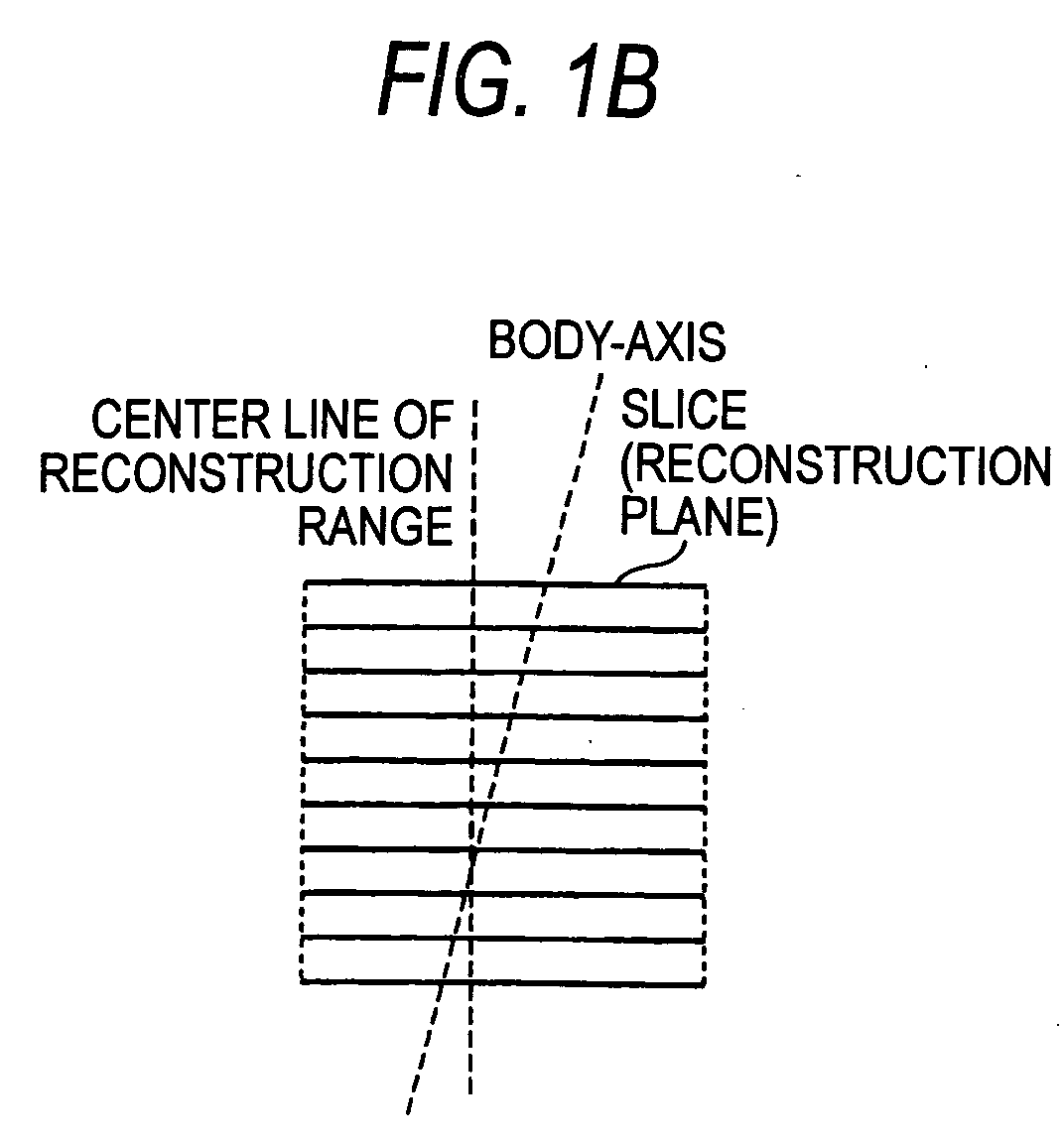
- The patient throughput has become one of critical issues associated with such achievement. Due to ultrafast scans as well as weight saving of X-ray tubes, widespread use of helical scan, increasing number of detector arrays, and enhancement of detection sensitivity in recent years, the patient throughput is influenced more by a time needed for pre-scan setting of the subject than the scan time. The subject lies on his back on the tabletop of the diagnostic table and fine adjusts the body position according to radiologist's instructions. However, only a limited time is allowed for fine adjustment of the body position. Hence, as is shown in FIG. 1A, scans are often performed while the body axis of the subject is tilted with respect to the center line (Z-axis, the rotational axis of the X-ray tube) of the scan range. This results in an event that, as is shown in FIG. 1B and FIG. 1C, the center of the subject is offset from the center of the image and a degree of offset differs from image to image, which makes observations quite difficult.
- An object of the invention is therefore to address an event such that scans are performed while the body axis of the subject is tilted with respect to the center line (Z-axis, the rotational axis of the X-ray tube) of the scan range.
- An X-ray computed tomographic apparatus of the invention includes: a display portion to display, on a screen, a scanogram related to a subject together with a quadrilateral frame line specifying a reconstruction range; an input portion to input a command to transform the frame line specifying the reconstruction range to a parallelogram or rotate the frame line specifying the reconstruction range; a gantry to perform scanning in a scan range corresponding to the reconstruction range; and a reconstruction portion to reconstruct image data related to plural slices, parallel to one another and included in the reconstruction range, slice-by-slice on the basis of projection data acquired by the scanning.
- This summary of the invention does not necessarily describe all necessary features so that the invention may also be a sub-combination of these described features.
- The invention can be more fully understood from the following detailed description when taken in conjunction with the accompanying drawings, in which:
- FIG. 1A, FIG. 1B, and FIG. 1C are views used to explain problems in the related art;
- FIG. 2 is a view showing the configuration of an X-ray computed tomographic apparatus according to an embodiment of the invention;
- FIG. 3A and FIG. 3B are perspective views of an X-ray detector of FIG. 2;
- FIG. 4 is a view showing helical path of an X-ray tube of FIG. 2;
- FIG. 5 is a view showing an example of a scan procedure screen constructed by a scan procedure system of FIG. 2;
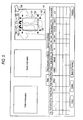
- FIG. 6 is a view showing a frame line specifying a reconstruction range transformed with a click on a "transformation icon" of FIG. 5;
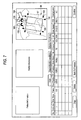
- FIG. 7 is a view showing a frame line specifying a reconstruction range rotated with a click on a "rotation icon" of FIG. 5;
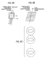
- FIG. 8A, FIG. 8B, and FIG. 8C are views used to explain reconstruction processing corresponding to the transformed reconstruction range of FIG. 6;
- FIG. 9A, FIG. 9B, and FIG. 9C are views used to explain reconstruction processing corresponding to the rotated reconstruction range of FIG. 7; and
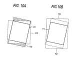
- FIG. 10A and FIG. 10B are views showing two types of scan range corresponding to the rotated reconstruction range of FIG. 7.
-
- An embodiment of an X-ray computed tomographic apparatus of the invention will now be described with reference to the accompanying drawings. The X-ray computed tomographic apparatus includes various types, such as a rotate/rotate type in which a unit comprising the X-ray tube and the radiation detector rotates about the subject, and a stationary/rotate type in which a number of detection elements are aligned in a ring-shaped array and the X-ray tube alone rotates about the subject, and the invention is applicable to any type. Herein, the currently most popular rotate/rotate type will be described. Also, in order to reconstruct tomographic data for one slice, it is necessary to obtain projection data of about 360° for a full circle of the subject, and projection data of 180° plus a view angle is needed even in the half scan method. The invention is applicable to either reconstruction method. Herein, the former method will be described by way of example. Also, popular mechanisms to convert incident X-rays to charges are: an indirect conversion scheme, by which X-rays are converted first into light by a fluorescent material, such as a scintillator, and the light is then converted to charges by a photoelectric converting element, such as a photodiode; and a direct conversion scheme, by which generation of electron-hole pairs in the semiconductor by X-rays and their movement to the electrodes, that is, the photoelectric phenomenon, are exploited. The X-ray detection elements adopting either scheme can be used, and herein, those adopting the former indirect conversion scheme will be described. In addition, a so-called multi-tube type X-ray computed tomographic apparatus, in which plural pairs of an X-ray tube and an X-ray detector are mounted to a rotational ring, has become commercially available recently, and the peripheral techniques are also under development. The invention is applicable to either a conventional single-tube type X-ray computed tomographic apparatus or a multi-tube type X-ray computed tomographic apparatus. Herein, a single-tube type X-ray computed tomographic apparatus will be described.
- FIG. 2 shows the configuration of the X-ray computed tomographic apparatus according to this embodiment. The X-ray computed tomographic apparatus includes a
gantry 1 configured to acquire projection data related to the subject. Thegantry 1 includes anX-ray tube 10 and anX-ray detector 23. Both theX-ray tube 10 and theX-ray detector 23 are mounted to a ring-shaped rotational frame 12, which is driven to rotate about the Z-axis by agantry driving device 25. The rotational frame 12 is provided with an aperture at the center thereof, and the subject P laid on thetabletop 2a of the diagnostic table 2 is inserted into the aperture. A slit 22 used to vary the irradiation width of X-rays depending on the slice thickness is placed between theX-ray tube 10 and the aperture. - A tube voltage from a high
voltage transformer assembly 21 is applied between the cathode and the anode of theX-ray tube 10, while a filament current from the highvoltage transformer assembly 21 is supplied to the filament of theX-ray tube 10. X-rays are generated by the application of the tube voltage and the supply of the filament current. - As is shown in FIG. 3A and FIG. 3B, the
X-ray detector 23 includes pluralX-ray detection elements 100 each having, for example, a 0.5 mm × 0.5 mm tetragonal light-reception surface. In the case of FIG. 3A, for example, 916X-ray detection elements 100 are aligned in an array along the channel direction. In the case of FIG. 3B, arrays of FIG. 3A are provided, for example, in 40 rows in parallel along the slice direction. The detector of FIG. 3A is referred to as the single-slice type, and the detector of FIG. 3B is referred to as the multi-slice type. TheX-ray detector 23 can be of either type. - A
data acquisition device 24, generally referred to as a DAS (data acquisition system), converts a signal in each channel outputted from thedetector 23 to a voltage signal, amplifies the voltage signal, and converts the amplified voltage signal to a digital signal. Data (raw data) thus obtained is supplied to a computer unit 3 installed at the outside of the gantry. Apre-processing unit 34 of the computer unit 3 performs compensation processing, such as sensitivity compensation, on the raw data outputted from thedata acquisition device 24, and outputs projection data. The projection data is then sent to and stored in adata storage device 35 of the computer system 3. - The computer system 3 comprises a
system controller 29, aninput device 39 provided with a keyboard, a mouse, etc., adisplay 38, ascan controller 30, areconstruction unit 36, and ascan procedure system 42 in addition to theaforementioned pre-processing unit 34 and thestorage device 35. Thereconstruction unit 36 is able to selectively perform the reconstruction processing according to either of the followings: the typical fan-beam reconstruction method (also referred to as the fan-beam convolution back projection method); and a reconstruction method in a case where projection rays cross with the reconstruction plane like a cone beam, other than the helical interpolation that can be used together with the fan-beam reconstruction method in finding projection data on the reconstruction plane through interpolation from projection data of, for example, two rotations, the method including the Feldkamp method, known as an approximate image reconstruction method, by which convolution is performed by deeming the beam as a fan projection beam on the assumption that the cone angle is small and back projection is performed along rays at the time of scanning, and the cone-beam reconstruction method, known as a method capable of suppressing cone-angle induced errors compared with the Feldkamp method, by which projection data is compensated in response to the angle of rays with respect to the reconstruction plane. - The
scan procedure system 42 is provided to assist the operator in a work of determining the scan procedure, and constructs a scan procedure screen used to set scan conditions, such as a helical pitch (HP) indicating a distance the tabletop moves while theX-ray tube 10 rotates once as shown in FIG. 4, and a scan speed (SS) indicating a time needed for theX-ray tube 10 to rotate once. - FIG. 5 shows an example of the scan procedure screen. The scan procedure screen includes patient information, gantry information, and detailed information of the scan conditions at the bottom of the screen as well as a
scanogram image 99. Thescanogram image 99 is displayed in an orientation such that the Z-axis (the center of rotation) thereof is parallel to the vertical direction (possibly, the horizontal direction in some cases) of the screen. Thus, when scanogram imaging is performed while the body axis of the subject is tilted with respect to the Z-axis, thescanogram image 99 is displayed on the screen as being tilted with respect to the vertical direction of the screen as well. - The scan conditions include the activation (distinction between the manual trigger and the automatic trigger to start the scan), scan start time (start time), start position of helical scan, a pause between scans, end position of helical scan, scan mode (distinction among single-slice/multi-slice/helical), start position of scan, end position of scan, tube voltage kV, tube current mA, scan speed (time in parentheses indicates a time needed for the entire scans), the number of slices (the number of arrays used), helical pitch, reconstruction mode, and FOV (width of reconstruction range).
- A
quadrilateral frame line 101 specifying the reconstruction range is displayed on thescanogram image 99. A frame line, generally in a dotted line, specifying the scan range corresponding to the reconstruction range is displayed together with theframe line 101 specifying the reconstruction range in some cases. Thequadrilateral frame line 101 specifying the reconstruction range is initially provided as an oblong with itscenter line 109 being parallel to the Z-axis (central axis of rotation). - Also,
rhombic icons 102 for scaling up/down the range vertically andrhombic icons 103 for scaling up/down the range horizontally are displayed at the four corners of theframe line 101 specifying the reconstruction range, so that the operator is able to scale up/down the reconstruction range as needed by moving thepointer 104 to any of theicons pointer 104 with the use of, for example, the mouse of theinput device 39. Also, the operator is able to move the reconstruction range in parallel vertically and/or horizontally by moving thepointer 104 on theframe line 101 and dragging thepointer 104 with the use of, for example, the mouse of theinput device 39. - Further, on the
scanogram image 99 are superposedtransformation icons rotation icons transformation icon 105. Upon input of the transformation command, as is shown in FIG. 6, theframe line 101 specifying the reconstruction range is transformed to a parallelogram. A degree of transformation, that is, a tilt of thecenter line 109 with respect to the vertical direction of the screen, is determined, for example, by the number of clicks. For instance, a tilt of 2.5° is given with one click. With a click on theother transformation icon 106, theframe line 101 specifying the reconstruction range is transformed in an opposite direction to the direction of FIG. 6. A degree of transformation is also determined by the number of clicks. - A rotation command is inputted with a click on the
rotation icon 107. Upon input of the rotation command, as is shown in FIG. 7, theframe line 101 specifying the reconstruction range is rotated about its center. A degree of rotation, that is, a tilt of thecenter line 109 with respect to the vertical direction of the screen, is determined, for example, by the number of clicks. For instance, a rotation by 2.5° is given with one click. With a click on theother rotation icon 108, theframe line 101 specifying the reconstruction range is rotated in a direction opposite to the direction of FIG. 7. A degree of rotation is also determined by the number of clicks. Basically, transformation and rotation are performed alternatively. - As has been described, the
scanogram image 99 is displayed in an orientation such that the Z-axis (center of rotation) thereof is parallel to the vertical direction of the screen. Thus, when scanogram imaging is performed while the subject is tilted with respect to the Z-axis, the tilt is reflected on thescanogram image 99 on the screen as are shown in FIG. 6 and FIG. 7. - The operator thus drags and moves the
frame line 101 specifying the reconstruction range in parallel and clicks either thetransformation icon 105 in the forward direction or thetransformation icon 106 in the backward direction as many times as necessary, so that thecenter line 109 of theframe line 101 specifying the reconstruction range becomes parallel to and agrees as much as possible with the body axis of the subject on the tiltedscanogram image 99. Also, the operator drags and moves theframe line 101 specifying the reconstruction range in parallel and clicks either therotation icon 107 in the forward direction or therotation icon 108 in the backward direction as many times as necessary, so that thecenter line 109 of theframe line 101 specifying the reconstruction range becomes parallel to and agrees as much as possible with the body axis of the subject assumed on the tiltedscanogram image 99. Alternatively, it may be possible to transform and rotate theframe line 101 specifying the reconstruction range with the use of thetransformation icon rotation icon - There is a slight difference between the examples of FIG. 6 and FIG. 7 in terms of image reconstruction. When the
frame line 101 specifying the reconstruction range is transformed as shown in FIG. 6, thescan procedure system 42 determines, as is shown in FIG. 8A, thereconstruction range 111 to correspond to theframe line 101, and determines thescan range 112 to correspond to thereconstruction range 111. Thescan range 112 is set to the shape of a cylindrical column whose longitudinal cross section is an oblong having the Z-axis (axis of rotation) at the center and covering thereconstruction range 111. - As is shown in FIG. 8B, the
reconstruction unit 36 extracts projection data corresponding to respective slices from projection data acquired by scans, and reconstructs image data on the basis of the projection data thus extracted. Widths of the respective slices are set according to the horizontal width of theframe line 101 specifying the reconstruction range, and the centers of the respective slices are set on thecenter line 109 of theframe line 101 specifying the reconstruction range. Because thecenter line 109 of the reconstruction range is set with a tilt with respect to the center line of the scan range, the horizontal positions of the respective slices, that is, a distance from the center line of the scan range to the center of each slice, vary from slice to slice. However, the centers of the respective slices are all placed on the body axis of the subject. - Because the center of the slice can be set for each slice in response to the tilted body position of the subject in the manner descried above, even when scans are performed while the body axis of the subject is titled with respect to the Z-axis, the body axis of the subject can be positioned on almost the center of the image as shown in FIG. 8C. This eliminates offset between the position on the image and the position on the subject, which makes observation quite easy. Also, by converting a horizontal distance of the subject to an actual distance on the basis of the tilt of the
frame line 101, it is possible to reduce errors in measurement of a distance or a volume. - Then, in a case where the
frame line 101 specifying the reconstruction range is rotated as shown in FIG. 7, thescan procedure system 42 determines, as is shown in FIG. 9A, thereconstruction range 111 corresponding to theframe line 101 together with thescan range 112. In this case, thescan range 112 is set to the shape of a cylindrical column whose longitudinal cross section is an oblong having the Z-axis (axis of rotation) at the center and covering thereconstruction range 111. - The
scan range 112 can be selected from the range shown in FIG. 10A and the range shown in FIG. 10B wider than the one shown in FIG. 10A. In the helical reconstruction, as is known, projection data at the slice position is generated through interpolation from projection data of two, preceding and following rotations. In other words, the helical reconstruction needs projection data that covers awider range 113, which is wider than the outermost slice within thereconstruction range 111 to the outside by at least one rotation. FIG. 10B shows an example when thescan range 112 is set to acquire the entire projection data of thiswider range 113. In contrast, FIG. 10A shows an example of anarrow scan range 112, in which part of projection data shaded by diagonal lines is replenished through extrapolative interpolation. The operator may make a selection between these two types, or the selection may be made automatically depending on the various conditions of the region to be imaged. - As is shown in FIG. 9B, the
reconstruction unit 36 reconstructs image data by either the cone-beam reconstruction method or the tilt reconstruction method for each of plural slices (reconstruction planes) orthogonal to thecenter line 109 of the reconstruction range rotated in response to a tilt of the body axis of the subject, on the basis of the projection data acquired by scans. In other words, the pixel value of each pixel within the slice tilted with respect to the central axis of the scan range is computed as a filter integral value of projection data of plural X-ray paths that cross with the each pixel diagonally. - The width of each slice is set according to the width of the
frame line 101 specifying the reconstruction range, and the center of each slice is set on thecenter line 109 of theframe line 101 specifying the reconstruction range. Because thecenter line 109 of the reconstruction range is set with a tilt with respect to the center line of the scan range, the horizontal positions of the respective slices, that is, a distance from the center line of the scan range to the center of each slice, vary from slice to slice. - Because the center of the slice can be set for each slice in response to the titled body position of the subject in the manner described above, even when scans are performed while the body axis of the subject is tilted with respect to the Z-axis, the body axis of the subject can be positioned on almost the center of the image as is shown in FIG. 9C. Moreover, in this example, an image of a plane orthogonal to the body axis of the subject can be obtained, which reduces errors in horizontal distance associated with a tilt of the body axis with respect to the Z-axis. In short, it is possible to substantially eliminate a state where the body axis of the subject is tilted with respect to the Z-axis. Because errors in distance can be eliminated not only vertically but also horizontally, errors can be reduced in measurement of a distance or a volume; moreover, MPR (multi-planar reconstruction) processing or 3-D processing can be performed directly without the need for special compensation processing.
- The invention can be applied to, for example, PET (Positron Emission computed Tomography), as an image diagnosis apparatus of a type that reconstructs a planar image on the basis of the subject's data acquired in many directions, as with the X-ray computed tomographic apparatus.
Claims (24)
- An X-ray computed tomographic apparatus, characterized by comprising:a display portion (38) to display, on a screen, a scanogram related to a subject together with a quadrilateral frame line specifying a reconstruction range;an input portion (39) to input a command to transform the frame line specifying said reconstruction range to a parallelogram or rotate the frame line specifying said reconstruction range;a scan portion (1) to perform scanning in a scan range corresponding to said reconstruction range; anda reconstruction portion (36) to reconstruct image data related to plural slices, parallel to one another and included in said reconstruction range, slice-by-slice on the basis of projection data acquired by said scanning.
- The X-ray computed tomographic apparatus according to claim 1, characterized in that:a center line of said transformed or rotated reconstruction range is tilted with respect to a center line of said scan range.
- The X-ray computed tomographic apparatus according to claim 2, characterized in that:a distance from the center line of said scan range to a center of each of said plural slices varies from slice to slice.
- The X-ray computed tomographic apparatus according to claim 2, characterized in that:said slices are tilted with respect to the center line of said transformed reconstruction range.
- The X-ray computed tomographic apparatus according to claim 4, characterized in that:said slices are orthogonal to the center line of said scan range.
- The X-ray computed tomographic apparatus according to claim 2, characterized in that:said slices are orthogonal to the center line of said rotated reconstruction range.
- The X-ray computed tomographic apparatus according to claim 6, characterized in that:said slices are tilted with respect to the center line of said scan range.
- The X-ray computed tomographic apparatus according to claim 1, characterized in that:an icon corresponding to transformation or rotation is displayed in the vicinity of the frame line specifying said reconstruction range.
- The X-ray computed tomographic apparatus according to claim 1, characterized in that:said scan range is set to a shape of a cylindrical column whose longitudinal cross section is an oblong having an axis of rotation at a center and covering said transformed or rotated reconstruction range.
- The X-ray computed tomographic apparatus according to claim 1, characterized in that:said scan range covers said transformed or rotated reconstruction range.
- The X-ray computed tomographic apparatus according to claim 10, characterized in that:said scan range has a length longer than said transformed or rotated reconstruction range with respect to a direction parallel to a central axis thereof.
- The X-ray computed tomographic apparatus according to claim 10, characterized in that:said scan range has a width almost equal to said transformed or rotated reconstruction range with respect to a direction orthogonal to a central axis thereof.
- A method for X-ray computed tomography, characterized by comprising:displaying, on a screen, a scanogram related to a subject together with a quadrilateral frame line specifying a reconstruction range;inputting a command to transform the frame line specifying said reconstruction range to a parallelogram or rotate the frame line specifying said reconstruction range;performing scanning in a scan range corresponding to said reconstruction range; andreconstructing image data related to plural slices, parallel to one another and included in said reconstruction range, slice-by-slice on the basis of projection data acquired by said scanning.
- The method for X-ray computed tomography according to claim 13, characterized in that:a center line of said transformed or rotated reconstruction range is tilted with respect to a center line of said scan range.
- The method for X-ray computed tomography according to claim 14, characterized in that:a distance from the center line of said scan range to a center of each of said plural slices varies from slice to slice.
- The method for X-ray computed tomography according to claim 14, characterized in that:said slices are tilted with respect to the center line of said transformed reconstruction range.
- The method for X-ray computed tomography according to claim 16, characterized in that:said slices are orthogonal to the center line of said scan range.
- The method for X-ray computed tomography according to claim 14, characterized in that:said slices are orthogonal to the center line of said rotated reconstruction range.
- The method for X-ray computed tomography according to claim 18, characterized in that:said slices are tilted with respect to the center line of said scan range.
- The method for X-ray computed tomography according to claim 13, characterized in that:an icon corresponding to transformation or rotation is displayed in the vicinity of the frame line specifying said reconstruction range.
- The method for X-ray computed tomography according to claim 13, characterized in that:said scan range is set to a shape of a cylindrical column whose longitudinal cross section is an oblong having an axis of rotation at a center and covering said transformed or rotated reconstruction range.
- The method for X-ray computed tomography according to claim 13, characterized in that:said scan range covers said transformed or rotated reconstruction range.
- The method for X-ray computed tomography according to claim 22, characterized in that:said scan range has a length longer than said transformed or rotated reconstruction range with respect to a direction parallel to a central axis thereof.
- The method for X-ray computed tomography according to claim 22, characterized in that:said scan range has a width almost equal to said transformed or rotated reconstruction range with respect to a direction orthogonal to a central axis thereof.
Applications Claiming Priority (2)
| Application Number | Priority Date | Filing Date | Title |
|---|---|---|---|
| JP2003091970A JP4469555B2 (en) | 2003-03-28 | 2003-03-28 | X-ray computed tomography system |
| JP2003091970 | 2003-03-28 |
Publications (2)
| Publication Number | Publication Date |
|---|---|
| EP1464286A1 true EP1464286A1 (en) | 2004-10-06 |
| EP1464286B1 EP1464286B1 (en) | 2008-04-30 |
Family
ID=32844589
Family Applications (1)
| Application Number | Title | Priority Date | Filing Date |
|---|---|---|---|
| EP04251467A Expired - Lifetime EP1464286B1 (en) | 2003-03-28 | 2004-03-15 | Apparatus and method for x-ray computed tomography |
Country Status (5)
| Country | Link |
|---|---|
| US (2) | US6987827B2 (en) |
| EP (1) | EP1464286B1 (en) |
| JP (1) | JP4469555B2 (en) |
| CN (1) | CN1294879C (en) |
| DE (1) | DE602004013394T2 (en) |
Cited By (1)
| Publication number | Priority date | Publication date | Assignee | Title |
|---|---|---|---|---|
| EP1970010A1 (en) * | 2007-03-13 | 2008-09-17 | Kabushiki Kaisha Toshiba | X-Ray CT system, object-outline estimating method, and image reconstructing method |
Families Citing this family (16)
| Publication number | Priority date | Publication date | Assignee | Title |
|---|---|---|---|---|
| JP4268909B2 (en) * | 2004-07-15 | 2009-05-27 | ジーイー・メディカル・システムズ・グローバル・テクノロジー・カンパニー・エルエルシー | Scanning plan communication method and X-ray CT apparatus |
| JP2006320523A (en) * | 2005-05-19 | 2006-11-30 | Ge Medical Systems Global Technology Co Llc | Method of setting scan parameter of shuttle mode helical scan and x-ray ct apparatus |
| JP4901159B2 (en) * | 2005-08-31 | 2012-03-21 | 株式会社東芝 | X-ray CT apparatus and X-ray imaging method |
| US7573974B2 (en) * | 2006-02-22 | 2009-08-11 | Novartis Ag | Device and method for non-contact scanning of contact lens and contact lens mold geometry |
| EP2005394B1 (en) * | 2006-04-06 | 2018-01-17 | Philips Intellectual Property & Standards GmbH | Method for reconstruction images and reconstruction system for reconstructing images |
| JP5389345B2 (en) * | 2007-10-04 | 2014-01-15 | ジーイー・メディカル・システムズ・グローバル・テクノロジー・カンパニー・エルエルシー | X-ray CT system |
| JP2009142300A (en) | 2007-12-11 | 2009-07-02 | Toshiba Corp | X-ray CT apparatus and scan plan creation method |
| JP5121889B2 (en) * | 2010-07-22 | 2013-01-16 | ジーイー・メディカル・システムズ・グローバル・テクノロジー・カンパニー・エルエルシー | X-ray CT system |
| US9057595B2 (en) | 2011-11-30 | 2015-06-16 | Novartis Ag | Combination of mirror images to improve signal quality for contact lenses |
| JP6113487B2 (en) * | 2012-12-13 | 2017-04-12 | 東芝メディカルシステムズ株式会社 | Medical image diagnostic apparatus and medical image processing apparatus |
| CN105283132B (en) * | 2013-05-27 | 2018-10-12 | 东芝医疗系统株式会社 | X ray CT device and image diagnosing system |
| CN105030266B (en) * | 2014-04-21 | 2018-01-12 | 东芝医疗系统株式会社 | X ray computed tomographics device and scan plan set supporting device |
| CN105433971A (en) * | 2014-07-29 | 2016-03-30 | 上海西门子医疗器械有限公司 | Computed tomography method and device |
| CN107049353A (en) * | 2017-05-12 | 2017-08-18 | 东北大学 | A kind of reduced form CT imaging systems |
| US20230079025A1 (en) * | 2021-09-10 | 2023-03-16 | Canon Kabushiki Kaisha | Information processing apparatus, information processing method, and non-transitory computer readable medium |
| JP1753079S (en) * | 2022-05-16 | 2023-09-14 | X-ray CT device |
Citations (6)
| Publication number | Priority date | Publication date | Assignee | Title |
|---|---|---|---|---|
| EP0485999A1 (en) * | 1990-11-14 | 1992-05-20 | Kabushiki Kaisha Toshiba | Method and apparatus for specifying slice planes in X-ray computed tomography |
| US6243436B1 (en) * | 1999-03-04 | 2001-06-05 | Siemens Aktiengeseuschaft | CT device for imaging slices that are inclined toward the system axis |
| JP2002008008A (en) * | 2000-06-27 | 2002-01-11 | Fuji Photo Film Co Ltd | Medical image output method and device therefor |
| US20020071599A1 (en) * | 2000-09-29 | 2002-06-13 | Martin Herget | Apparatus for reference image rotation, and computer software product and method for reference image rotation |
| US20020181646A1 (en) * | 2001-05-31 | 2002-12-05 | Siemens Aktiengesellschaft | Method for operating a computed tomography apparatus |
| US20030023166A1 (en) * | 2000-08-17 | 2003-01-30 | Janice Frisa | Biplane ultrasonic imaging |
Family Cites Families (24)
| Publication number | Priority date | Publication date | Assignee | Title |
|---|---|---|---|---|
| US5287546A (en) * | 1992-09-14 | 1994-02-15 | Lunar Corporation | Patient positioning apparatus for bone scanning |
| US5588036A (en) * | 1993-06-28 | 1996-12-24 | Kabushiki Kaisha Toshiba | X-ray CT apparatus and radiographing method using same |
| DE4405505A1 (en) * | 1994-02-21 | 1995-08-31 | Siemens Ag | Computer tomograph for examination of hollow organs of patients |
| DE69529857T2 (en) * | 1994-03-25 | 2004-01-08 | Kabushiki Kaisha Toshiba, Kawasaki | Radiotherapy System |
| US5673300A (en) * | 1996-06-11 | 1997-09-30 | Wisconsin Alumni Research Foundation | Method of registering a radiation treatment plan to a patient |
| EP0825457A3 (en) * | 1996-08-19 | 2002-02-13 | Analogic Corporation | Multiple angle pre-screening tomographic systems and methods |
| US5802134A (en) * | 1997-04-09 | 1998-09-01 | Analogic Corporation | Nutating slice CT image reconstruction apparatus and method |
| DE19721535C2 (en) * | 1997-05-22 | 2001-09-06 | Siemens Ag | X-ray computer tomograph for generating X-ray silhouettes |
| US6188744B1 (en) * | 1998-03-30 | 2001-02-13 | Kabushiki Kaisha Toshiba | X-ray CT apparatus |
| US6195409B1 (en) * | 1998-05-22 | 2001-02-27 | Harbor-Ucla Research And Education Institute | Automatic scan prescription for tomographic imaging |
| US6061420A (en) * | 1998-08-25 | 2000-05-09 | General Electric Company | Methods and apparatus for graphical Rx in a multislice imaging system |
| US6229869B1 (en) * | 1998-08-25 | 2001-05-08 | General Electric Company | Tilted gantry image correction for a multislice computed tomography system |
| US6185271B1 (en) * | 1999-02-16 | 2001-02-06 | Richard Estyn Kinsinger | Helical computed tomography with feedback scan control |
| DE19908494A1 (en) * | 1999-02-26 | 2000-10-05 | Siemens Ag | Computer tomography unit with gantry movement independent of patients couch |
| JP4519254B2 (en) * | 2000-04-03 | 2010-08-04 | 株式会社日立メディコ | X-ray CT system |
| US6568851B2 (en) * | 2000-10-25 | 2003-05-27 | Kabushiki Kaisha Toshiba | X-ray CT scanner |
| JP2002272729A (en) | 2001-03-14 | 2002-09-24 | Hitachi Medical Corp | Imaging position setting method, program for implementing this method, and medical image display system |
| DE10127269B4 (en) * | 2001-06-05 | 2015-09-24 | Siemens Aktiengesellschaft | Method for computed tomography and computed tomography (CT) device |
| US6990170B2 (en) * | 2001-08-09 | 2006-01-24 | Kabushiki Kaisha Toshiba | X-ray computed tomographic imaging apparatus |
| WO2003092502A1 (en) * | 2002-05-06 | 2003-11-13 | Philips Medical Systems Technologies Ltd. | Cone beam ct scanners with reduced scan length |
| JP4331444B2 (en) * | 2002-07-22 | 2009-09-16 | 株式会社日立メディコ | Imaging condition setting apparatus for medical image diagnostic apparatus |
| JP4679068B2 (en) * | 2004-04-26 | 2011-04-27 | 株式会社東芝 | X-ray computed tomography system |
| US7215733B2 (en) * | 2004-07-23 | 2007-05-08 | Kabushiki Kaisha Toshiba | X-ray computed tomography apparatus |
| US7302038B2 (en) * | 2004-09-24 | 2007-11-27 | Wisconsin Alumni Research Foundation | Correction of patient rotation errors in radiotherapy using couch translation |
-
2003
- 2003-03-28 JP JP2003091970A patent/JP4469555B2/en not_active Expired - Lifetime
-
2004
- 2004-03-12 US US10/798,435 patent/US6987827B2/en not_active Ceased
- 2004-03-15 EP EP04251467A patent/EP1464286B1/en not_active Expired - Lifetime
- 2004-03-15 DE DE602004013394T patent/DE602004013394T2/en not_active Expired - Lifetime
- 2004-03-26 CN CNB200410031296XA patent/CN1294879C/en not_active Expired - Fee Related
-
2006
- 2006-06-12 US US11/450,952 patent/USRE41219E1/en not_active Expired - Fee Related
Patent Citations (6)
| Publication number | Priority date | Publication date | Assignee | Title |
|---|---|---|---|---|
| EP0485999A1 (en) * | 1990-11-14 | 1992-05-20 | Kabushiki Kaisha Toshiba | Method and apparatus for specifying slice planes in X-ray computed tomography |
| US6243436B1 (en) * | 1999-03-04 | 2001-06-05 | Siemens Aktiengeseuschaft | CT device for imaging slices that are inclined toward the system axis |
| JP2002008008A (en) * | 2000-06-27 | 2002-01-11 | Fuji Photo Film Co Ltd | Medical image output method and device therefor |
| US20030023166A1 (en) * | 2000-08-17 | 2003-01-30 | Janice Frisa | Biplane ultrasonic imaging |
| US20020071599A1 (en) * | 2000-09-29 | 2002-06-13 | Martin Herget | Apparatus for reference image rotation, and computer software product and method for reference image rotation |
| US20020181646A1 (en) * | 2001-05-31 | 2002-12-05 | Siemens Aktiengesellschaft | Method for operating a computed tomography apparatus |
Non-Patent Citations (1)
| Title |
|---|
| PATENT ABSTRACTS OF JAPAN vol. 2002, no. 05 3 May 2002 (2002-05-03) * |
Cited By (2)
| Publication number | Priority date | Publication date | Assignee | Title |
|---|---|---|---|---|
| EP1970010A1 (en) * | 2007-03-13 | 2008-09-17 | Kabushiki Kaisha Toshiba | X-Ray CT system, object-outline estimating method, and image reconstructing method |
| US8416913B2 (en) | 2007-03-13 | 2013-04-09 | Kabushiki Kaisha Toshiba | X-ray CT system, object-outline estimating method, and image reconstructing method |
Also Published As
| Publication number | Publication date |
|---|---|
| USRE41219E1 (en) | 2010-04-13 |
| US6987827B2 (en) | 2006-01-17 |
| JP4469555B2 (en) | 2010-05-26 |
| DE602004013394D1 (en) | 2008-06-12 |
| EP1464286B1 (en) | 2008-04-30 |
| CN1541618A (en) | 2004-11-03 |
| CN1294879C (en) | 2007-01-17 |
| US20040190674A1 (en) | 2004-09-30 |
| DE602004013394T2 (en) | 2009-06-10 |
| JP2004298247A (en) | 2004-10-28 |
Similar Documents
| Publication | Publication Date | Title |
|---|---|---|
| US7203270B2 (en) | X-ray computed tomographic apparatus | |
| US6990170B2 (en) | X-ray computed tomographic imaging apparatus | |
| US7113569B2 (en) | X-ray CT apparatus | |
| EP1464286B1 (en) | Apparatus and method for x-ray computed tomography | |
| US6421412B1 (en) | Dual cardiac CT scanner | |
| US6665370B2 (en) | Computed tomography method and apparatus for acquiring images dependent on a time curve of a periodic motion of the subject | |
| US6922457B2 (en) | Computer tomography apparatus | |
| CN100381105C (en) | X-ray computed tomography device | |
| US6928137B2 (en) | Method for generating an image by means of a tomography capable X-ray device with multi-row X-ray detector array | |
| US20040114727A1 (en) | Method and apparatus for imaging a region of dynamic tissue | |
| US20050185760A1 (en) | X-ray computed tomography apparatus with x-ray intensity control | |
| US7257190B2 (en) | Radiographic device and control method therefor | |
| JP2004160218A (en) | X-ray computed tomography apparatus, X-ray computed tomography apparatus control method, and X-ray computed tomography program | |
| KR20070057055A (en) | X-ray CT device and its control method | |
| US7215805B2 (en) | Method and apparatus for spiral scan computed tomography | |
| US7298813B2 (en) | X-ray computed tomographic apparatus, image processing apparatus, and image processing method | |
| US7020236B2 (en) | Cone beam CT scanners with reduced scan length | |
| JP4621425B2 (en) | X-ray computed tomography system | |
| JP2001128964A (en) | Method and apparatus for pre-filtering weights in image reconstruction | |
| JP4598302B2 (en) | Method and apparatus for generating thin layer slice imaging data in a multi-slice imaging system | |
| JP4551612B2 (en) | Computed tomography equipment | |
| JPH0921876A (en) | Improved gamma camera imaging system | |
| US9784694B2 (en) | X-ray computed tomography apparatus and reconstruction processing method | |
| US10786212B1 (en) | System and method of helical cardiac cone beam reconstruction | |
| JPS6311014B2 (en) |
Legal Events
| Date | Code | Title | Description |
|---|---|---|---|
| PUAI | Public reference made under article 153(3) epc to a published international application that has entered the european phase |
Free format text: ORIGINAL CODE: 0009012 |
|
| 17P | Request for examination filed |
Effective date: 20040407 |
|
| AK | Designated contracting states |
Kind code of ref document: A1 Designated state(s): AT BE BG CH CY CZ DE DK EE ES FI FR GB GR HU IE IT LI LU MC NL PL PT RO SE SI SK TR |
|
| AX | Request for extension of the european patent |
Extension state: AL HR LT LV MK |
|
| AKX | Designation fees paid |
Designated state(s): DE |
|
| 17Q | First examination report despatched |
Effective date: 20050906 |
|
| GRAP | Despatch of communication of intention to grant a patent |
Free format text: ORIGINAL CODE: EPIDOSNIGR1 |
|
| GRAS | Grant fee paid |
Free format text: ORIGINAL CODE: EPIDOSNIGR3 |
|
| GRAA | (expected) grant |
Free format text: ORIGINAL CODE: 0009210 |
|
| AK | Designated contracting states |
Kind code of ref document: B1 Designated state(s): DE |
|
| REF | Corresponds to: |
Ref document number: 602004013394 Country of ref document: DE Date of ref document: 20080612 Kind code of ref document: P |
|
| PLBE | No opposition filed within time limit |
Free format text: ORIGINAL CODE: 0009261 |
|
| STAA | Information on the status of an ep patent application or granted ep patent |
Free format text: STATUS: NO OPPOSITION FILED WITHIN TIME LIMIT |
|
| 26N | No opposition filed |
Effective date: 20090202 |
|
| PGFP | Annual fee paid to national office [announced via postgrant information from national office to epo] |
Ref country code: DE Payment date: 20110329 Year of fee payment: 8 |
|
| REG | Reference to a national code |
Ref country code: DE Ref legal event code: R119 Ref document number: 602004013394 Country of ref document: DE Effective date: 20121002 |
|
| PG25 | Lapsed in a contracting state [announced via postgrant information from national office to epo] |
Ref country code: DE Free format text: LAPSE BECAUSE OF NON-PAYMENT OF DUE FEES Effective date: 20121002 |