EP1464276B1 - Device for measuring blood flow in an organ - Google Patents
Device for measuring blood flow in an organ Download PDFInfo
- Publication number
- EP1464276B1 EP1464276B1 EP04101074A EP04101074A EP1464276B1 EP 1464276 B1 EP1464276 B1 EP 1464276B1 EP 04101074 A EP04101074 A EP 04101074A EP 04101074 A EP04101074 A EP 04101074A EP 1464276 B1 EP1464276 B1 EP 1464276B1
- Authority
- EP
- European Patent Office
- Prior art keywords
- organ
- function
- tissue
- indicator
- blood flow
- Prior art date
- Legal status (The legal status is an assumption and is not a legal conclusion. Google has not performed a legal analysis and makes no representation as to the accuracy of the status listed.)
- Expired - Lifetime
Links
- 210000000056 organ Anatomy 0.000 title claims description 22
- 230000017531 blood circulation Effects 0.000 title claims description 10
- 210000004369 blood Anatomy 0.000 claims description 26
- 239000008280 blood Substances 0.000 claims description 25
- 230000000541 pulsatile effect Effects 0.000 claims description 19
- 230000002490 cerebral effect Effects 0.000 claims description 16
- 230000005855 radiation Effects 0.000 claims description 16
- 238000011156 evaluation Methods 0.000 claims description 15
- 230000003727 cerebral blood flow Effects 0.000 claims description 14
- 238000004364 calculation method Methods 0.000 claims description 12
- 238000005259 measurement Methods 0.000 claims description 8
- 238000002347 injection Methods 0.000 claims description 5
- 239000007924 injection Substances 0.000 claims description 5
- 238000010521 absorption reaction Methods 0.000 claims description 4
- 229960004657 indocyanine green Drugs 0.000 claims description 3
- 210000004556 brain Anatomy 0.000 claims description 2
- 230000007423 decrease Effects 0.000 claims description 2
- BDBMLMBYCXNVMC-UHFFFAOYSA-O 4-[(2e)-2-[(2e,4e,6z)-7-[1,1-dimethyl-3-(4-sulfobutyl)benzo[e]indol-3-ium-2-yl]hepta-2,4,6-trienylidene]-1,1-dimethylbenzo[e]indol-3-yl]butane-1-sulfonic acid Chemical group OS(=O)(=O)CCCCN1C2=CC=C3C=CC=CC3=C2C(C)(C)C1=CC=CC=CC=CC1=[N+](CCCCS(O)(=O)=O)C2=CC=C(C=CC=C3)C3=C2C1(C)C BDBMLMBYCXNVMC-UHFFFAOYSA-O 0.000 claims 1
- 238000013213 extrapolation Methods 0.000 claims 1
- 230000003287 optical effect Effects 0.000 description 9
- 238000004497 NIR spectroscopy Methods 0.000 description 5
- 238000000034 method Methods 0.000 description 4
- 102000001554 Hemoglobins Human genes 0.000 description 2
- 108010054147 Hemoglobins Proteins 0.000 description 2
- 230000005540 biological transmission Effects 0.000 description 2
- 230000001419 dependent effect Effects 0.000 description 2
- 238000010790 dilution Methods 0.000 description 2
- 239000012895 dilution Substances 0.000 description 2
- 230000000004 hemodynamic effect Effects 0.000 description 2
- MOFVSTNWEDAEEK-UHFFFAOYSA-M indocyanine green Chemical compound [Na+].[O-]S(=O)(=O)CCCCN1C2=CC=C3C=CC=CC3=C2C(C)(C)C1=CC=CC=CC=CC1=[N+](CCCCS([O-])(=O)=O)C2=CC=C(C=CC=C3)C3=C2C1(C)C MOFVSTNWEDAEEK-UHFFFAOYSA-M 0.000 description 2
- 238000012905 input function Methods 0.000 description 2
- 238000012544 monitoring process Methods 0.000 description 2
- 238000006213 oxygenation reaction Methods 0.000 description 2
- 230000002792 vascular Effects 0.000 description 2
- 229910052724 xenon Inorganic materials 0.000 description 2
- 208000032851 Subarachnoid Hemorrhage Diseases 0.000 description 1
- 238000013459 approach Methods 0.000 description 1
- 230000015556 catabolic process Effects 0.000 description 1
- 230000004087 circulation Effects 0.000 description 1
- 238000006731 degradation reaction Methods 0.000 description 1
- 238000005516 engineering process Methods 0.000 description 1
- 238000012854 evaluation process Methods 0.000 description 1
- 239000000835 fiber Substances 0.000 description 1
- 208000001286 intracranial vasospasm Diseases 0.000 description 1
- 210000004185 liver Anatomy 0.000 description 1
- 238000000691 measurement method Methods 0.000 description 1
- 238000002600 positron emission tomography Methods 0.000 description 1
- 239000000700 radioactive tracer Substances 0.000 description 1
- 238000002603 single-photon emission computed tomography Methods 0.000 description 1
- 238000004611 spectroscopical analysis Methods 0.000 description 1
- 238000001356 surgical procedure Methods 0.000 description 1
- 230000036962 time dependent Effects 0.000 description 1
- FHNFHKCVQCLJFQ-UHFFFAOYSA-N xenon atom Chemical compound [Xe] FHNFHKCVQCLJFQ-UHFFFAOYSA-N 0.000 description 1
Images

Classifications
-
- A—HUMAN NECESSITIES
- A61—MEDICAL OR VETERINARY SCIENCE; HYGIENE
- A61B—DIAGNOSIS; SURGERY; IDENTIFICATION
- A61B5/00—Measuring for diagnostic purposes; Identification of persons
- A61B5/02—Detecting, measuring or recording pulse, heart rate, blood pressure or blood flow; Combined pulse/heart-rate/blood pressure determination; Evaluating a cardiovascular condition not otherwise provided for, e.g. using combinations of techniques provided for in this group with electrocardiography or electroauscultation; Heart catheters for measuring blood pressure
- A61B5/026—Measuring blood flow
- A61B5/0275—Measuring blood flow using tracers, e.g. dye dilution
-
- A—HUMAN NECESSITIES
- A61—MEDICAL OR VETERINARY SCIENCE; HYGIENE
- A61B—DIAGNOSIS; SURGERY; IDENTIFICATION
- A61B5/00—Measuring for diagnostic purposes; Identification of persons
- A61B5/02—Detecting, measuring or recording pulse, heart rate, blood pressure or blood flow; Combined pulse/heart-rate/blood pressure determination; Evaluating a cardiovascular condition not otherwise provided for, e.g. using combinations of techniques provided for in this group with electrocardiography or electroauscultation; Heart catheters for measuring blood pressure
- A61B5/026—Measuring blood flow
- A61B5/0261—Measuring blood flow using optical means, e.g. infrared light
-
- A—HUMAN NECESSITIES
- A61—MEDICAL OR VETERINARY SCIENCE; HYGIENE
- A61B—DIAGNOSIS; SURGERY; IDENTIFICATION
- A61B5/00—Measuring for diagnostic purposes; Identification of persons
- A61B5/40—Detecting, measuring or recording for evaluating the nervous system
- A61B5/4058—Detecting, measuring or recording for evaluating the nervous system for evaluating the central nervous system
- A61B5/4064—Evaluating the brain
Definitions
- the present invention relates to a device for measuring the blood flow in an organ by means of an injected indicator.
- NIRS near infrared spectroscopy
- the use of such devices requires the invasive measurement of the input function, i. the arterial concentration of the indicator over time.
- the input function i. the arterial concentration of the indicator over time.
- arterial fiber optic catheters are used.
- PET positron emission tomography
- SPECT single-photon emission computed tomography
- perfusion-weighted magnetic resonance spectroscopy are technically feasible only with extremely expensive devices and require in use the sometimes considerable risks of transporting the patient to the measuring unit; i.e. the corresponding devices can not be used as so-called "bedside" devices at the patient's bed.
- An essential object of the present invention is to provide a device with which higher accuracies can be achieved in the determination of the blood flow in an organ, in particular of the cerebral blood flow.
- the accuracy of the evaluation result is less dependent on the boundary conditions, ie in particular on the execution of the indicator injection.
- the device to be created should be non-invasively applicable and feasible with reasonable technical effort.
- this object is achieved with a device according to claim 1.
- Advantageous embodiments of the device according to the invention are described in claims 2 to 12.
- One of the advantages of the present invention is that the sharpness of the first peak of the measurement signal after indicator input - completely surprising to those skilled in the art - is no longer decisive for the accuracy of the achievable results, since the evaluation unit due to their programmer device according to the invention, the indicator effluent the organ is taken into account during the first rise of the input signal.
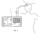
- the device according to the invention shown schematically in FIG. 1 serves to determine the cerebral blood flow of a patient, for example an intensive care patient in neurosurgery.
- a first optode 2 and a second optode 3 are fastened in a mutually optimized distance by means of an elastic band (not shown).
- a radiation source (not shown) for emitting near-infrared radiation into the cerebral tissue of the patient is arranged either in the first optode 2 itself, or separately therefrom, for example in a common housing with the evaluation unit 4, the near-infrared radiation in the latter case a light guide is guided to the first optode 2 and emitted there.
- the wavelength of the emitted radiation and the indicator used must be coordinated.
- a wavelength of about 805 nm (but in any case in the range between 780 and 910 nm) is ideal.
- the intensity of the part of the cerebral tissue emerging at the location of the second optode 3 Infrared radiation is detected by this and transmitted to the evaluation unit 4.
- the concentration of the indicator injected into the patient in the cerebral tissue depends on the indicator concentration in the blood flowing through the tissue and on the amount of blood flowing through the tissue. The latter changes periodically with the heartbeat, so the resulting intensity signal is pulsatile, i. periodically fluctuating proportion. The pulsatile portion of the intensity signal is superimposed on a non-pulsatile portion.
- the indicator concentration in the blood flowing through the tissue changes over time because the blood flowing out of the cerebral tissue has a different concentration than the inflowing blood. Partly responsible for this concentration difference is the distribution kinetics of the indicator in the cerebral vascular system.
- the indicator concentration in recirculated (re-inflowing) blood is determined by the distribution kinetics of the indicator in the whole circulation and by the degradation of the indicator in the liver.
- the evaluation unit 4 is program-technically designed to carry out the evaluation steps listed in FIG. 2 in the form of a flowchart and explained below.
- the optical density OD is formed as a negative decadic logarithm of the transmission.
- Transmission is understood here as the quotient of the intensity of the detected near-infrared radiation and the intensity of the emitted near-infrared radiation (and not in the strict physical sense, since the detected radiation has scattered and reflected components).
- the (time-dependent) optical density which is substantially proportional to the indicator concentration in the tissue, is divided into its pulsatile and non-pulsatile portions.
- an inflow function i (t) corresponding to the arterial input function of the brain is iteratively determined.
- the course of the iteration is shown in the left branch of the scheme shown in FIG.
- the mean transit time mtt is sometimes referred to as "transit time” and is a characteristic residence time which corresponds to the time it takes for a volume element on average to pass through the system under consideration.
- the time variable t and for the range t ⁇ 0, the inflow function i (t) and the associated outflow function o (t) are set to zero.
- the inflow function i (t) describes the proportion of changes in the concentration of the indicator in the cerebral tissue originating from the inflowing blood quantity
- Each iteration step involves the stepwise calculation of an approximation of the inflow function i (t) and an approximation of the outflow function o (t) and the calculation of an approximation of the transport function g (t), so that the mth approximation of the inflow function with the mth iteration step i (t), the outflow function o (t) and the transport function g (t) is calculated (m is the count variable).
- t k is a constant, small time interval, so that for o (tt k ) the value of the outflow function at time tt k is to be used.
- d / dt C tissue (t) expresses the change in cerebral tissue indicator concentration.
- ⁇ is a constant parameter chosen for the system based on empirical values (which basically describes the width of an assumed residence time distribution).
- the plausibility criterion ie termination criterion of the iteration
- the plausibility criterion may include that the inflow function i (t) can be represented as the sum of a finite number of functions which are similar to the form of the transport function g (t).
- the average transit time mtt is adjusted by an increment or decrement by one increment and another iteration step is performed, which in turn begins with the initialization step and proceeds as shown ,
- the indicator concentration is determined in the tissue, as shown in the right branch of the scheme shown in Fig. 2.
- the time t2 is chosen so that a complete mixing of the indicator is ensured with the blood, ie no recirculation-based concentration peak is more detectable.
- the value of the non-pulsatile component is determined in the range t ⁇ 0, ie OD (t ⁇ 0).
- tissue OD ( t ⁇ 0 ) - OD t ⁇ 0 / ⁇ ICG
- ⁇ ICG is the absorption coefficient of the indicator
- 0D (t-> 0) corresponds to the value of the optical density OD from the back-extrapolated function curve for t versus 0.
- Evaluation steps implemented to take account of the pulsatile fraction are listed in the middle branch of FIG.
- An envelope is adapted to the pulsatile portion of the time course of the optical density OD. Further, the amplitude AOD (t ⁇ 0), that is, the amplitude of the pulsatile portion of the optical density for t ⁇ 0 is determined.
- the indicator concentration in the blood C blood required for the calculation of the cerebral blood flow CBV is calculated according to the following formula, where A OD (t-> 0) corresponds to the value of the amplitude of the optical density for t against 0 (obtained from the back-extrapolated function) value determined by direct measurement is less strongly dependent on the sharpness of the first signal peak after indicator input):
- C blood ( A OD t ⁇ 0 A OD t ⁇ 0 - 1 ) ⁇ hb ⁇ C hb ⁇ ICG ,
- ⁇ ICG is the absorption coefficient of the indicator
- ⁇ Hb is the absorption coefficient of hemoglobin
- C Hb is the hemoglobin concentration in the blood.
Description
Die vorliegende Erfindung betrifft eine Vorrichtung zur Messung des Blutflusses in einem Organ mit Hilfe eines injizierten Indikators.The present invention relates to a device for measuring the blood flow in an organ by means of an injected indicator.
Vorrichtungen zur Messung des Blutflusses in einem Organ, insbesondere des cerebralen Blutflusses (CBF), mit Hilfe eines injizierten, weitgehend inerten Indikators sind seit langem bekannt und teilweise auch im klinischen Einsatz. Auf älteren Verfahren, wie etwa der Xenon-Dilutionstechnik (Obrist, W. D., Thompson, H. K., Wang, H. S., and Wilkinson, W. E. 1975. Regional cerebral blood flow estimated by 133-xenon inhalation. Stroke 6: 245-256), basierende Vorrichtungen sind oft schwierig technisch umsetzbar und erweisen sich im Einsatz als zeitaufwendig. In jüngerer Zeit haben vor allem Technologien an Bedeutung gewonnen, welche die Nahinfrarotspektroskopie (NIRS) in Verbindung mit Indocyningrün (ICG) als Indikator einsetzen, um die cerebrale Durchblutung zu untersuchen bzw. zu überwachen.Devices for measuring the blood flow in an organ, in particular the cerebral blood flow (CBF), using an injected, largely inert indicator have long been known and sometimes in clinical use. Devices based on older methods, such as the xenon dilution technique (Obrist, WD, Thompson, HK, Wang, HS, and Wilkinson, WE 1975. Regional Cerebral Blood Flow Estimated by 133-xenon inhalation, Stroke 6: 245-256) are often difficult to implement technically and in use prove to be time consuming. More recently, technologies that use near infrared spectroscopy (NIRS) in conjunction with indocynine green (ICG) as an indicator to monitor cerebral blood flow have gained in importance.
In aller Regel erfordert der Einsatz derartiger Vorrichtungen die invasive Messung der Eingangsfunktion, d.h. der arteriellen Konzentration des Indikators über die Zeit. Dabei finden beispielsweise arterielle Faseroptikkatheter Verwendung.In general, the use of such devices requires the invasive measurement of the input function, i. the arterial concentration of the indicator over time. For example, arterial fiber optic catheters are used.
In jüngster Zeit wurde auch die Anwendung nichtinvasiver Meßmethoden zur Überwachung der Gehirndurchblutung vorgeschlagen (Keller, E., Wolf, M., Martin, M., Fandino, J. and Yonekawa Y 2001. Estimation of cerebral oxygenation and hemodynamics in cerebral vasospasm using indocyaningreen (ICG) dye dilution and near infrared spectroscopy (NIRS). A case report. J. Neurosurg. Anesthesiol. 13: 43-48). Dabei werden Optoden am Kopf angebracht, welche als Sender bzw. Empfänger der nahinfraroten Strahlung fungieren, mittels welcher die Indikatorkonzentration im cerebralen Gefäßsystem bestimmt wird. Die zur Auswertung verwendeten Algorithmen sind in der Literatur beschrieben (Keller, E., Nadler, A., Imhof, H.-G., Niederer, P., Roth, P. and Yonekawa Y. 2002. New Methods fo Monitoring Cerebral Oxygenation and Hemodynamics in Patients with Subarachnoid Hemorrhage. Acta Neurochir. [Suppl.]82: 87-92).Recently, the use of noninvasive measurement techniques for monitoring cerebral blood flow has also been proposed (Keller, E., Wolf, M., Martin, M., Fandino, J. and Yonekawa Y 2001. Estimation of cerebral oxygenation and hemodynamics in cerebral vasospasm using indocyanine green (ICG) dye dilution and near infrared spectroscopy (NIRS), A case report, J. Neurosurg., Anesthesiol 13: 43-48). Optodes are attached to the head, which as transmitter or receiver of the act near-infrared radiation, by means of which the indicator concentration is determined in the cerebral vascular system. The algorithms used for the evaluation are described in the literature (Keller, E., Nadler, A., Imhof, H.-G., Niederer, P., Roth, P. and Yonekawa Y. 2002. New Methods for Monitoring Cerebral Oxygenation and Hemodynamics in Patients with Subarachnoid Hemorrhage, Acta Neurochir. [Suppl.] 82: 87-92).
Ein wesentliches Problem herkömmlicher NIRS-Vorrichtungen besteht darin, daß deren Auswerteeinheiten mit einer gewissen Ungenauigkeit arbeiten, welche darauf beruht, daß bei der Auswertung bisher von der vereinfachenden Annahme ausgegangen wird, während des ersten Anstiegs des Eingangssignals (der sogenannten "rise time") finde kein Abfluß des Indikators aus dem untersuchten System statt. Die Genauigkeit der im Rahmen der Auswertung gelieferten Ergebnisse hängt somit entscheidend von der Schärfe des ersten Peaks des Meßsignals nach der Indikatorgabe ab. Da sich aus einleuchtenden praktischen Gründen die Injektion des Indikators nicht in beliebig kurzer Zeit und nicht beliebig nah am Meßort realisieren läßt, war die Abhängigkeit der Qualität der Meßergebnisse von der Schärfe des ersten Peaks des Meßsignals nach der Indikatorgabe bisher als prinzipbedingt hinzunehmen.An essential problem of conventional NIRS devices is that their evaluation work with a certain degree of inaccuracy, which is based on the fact that in the evaluation has been assumed by the simplistic assumption, during the first rise of the input signal (the so-called "rise time") find no outflow of the indicator from the system studied instead. The accuracy of the results obtained in the evaluation thus depends crucially on the sharpness of the first peak of the measurement signal after the indicator input. Since, for obvious practical reasons, the injection of the indicator can not be realized in arbitrarily short time and not arbitrarily close to the measuring location, the dependence of the quality of the measurement results on the sharpness of the first peak of the measuring signal after the indicator input was previously accepted as a matter of principle.
Alternative Meßmethoden, wie etwa die Positronenemissionstomographie (PET), die Einzelphotonenemissionscomputertomographie (SPECT) oder die perfusionsgewichtete magnetische Resonanzspektroskopie, sind nur mittels äußerst kostspieliger Vorrichtungen technisch umsetzbar und erfordern im Einsatz den mitunter beträchtliche Risiken bergenden Transport des betreffenden Patienten zu der Meßeinheit; d.h. die entsprechenden Vorrichtungen lassen sich nicht als sogenannte "bedside"-Apparaturen am Patientenbett einsetzen.Alternative methods of measurement, such as positron emission tomography (PET), single-photon emission computed tomography (SPECT) or perfusion-weighted magnetic resonance spectroscopy, are technically feasible only with extremely expensive devices and require in use the sometimes considerable risks of transporting the patient to the measuring unit; i.e. the corresponding devices can not be used as so-called "bedside" devices at the patient's bed.
Eine wesentliche Aufgabe der vorliegenden Erfindung besteht darin, eine Vorrichtung zu schaffen, mit welcher sich höhere Genauigkeiten bei der Bestimmung des Blutflusses in einem Organ, insbesondere des cerebralen Blutflusses, erzielen lassen. Insbesondere soll die Genauigkeit des Auswerteergebnisses weniger stark von den Randbedingungen, d.h. insbesondere von der Ausführung der Indikatorinjektion abhängen. Ferner soll die zu schaffende Vorrichtung nicht-invasiv einsetzbar und mit vertretbarem technischen Aufwand realisierbar sein.An essential object of the present invention is to provide a device with which higher accuracies can be achieved in the determination of the blood flow in an organ, in particular of the cerebral blood flow. In particular, the accuracy of the evaluation result is less dependent on the boundary conditions, ie in particular on the execution of the indicator injection. Furthermore, the device to be created should be non-invasively applicable and feasible with reasonable technical effort.
Gemäß einem Aspekt der vorliegenden Erfindung wird diese Aufgabenstellung mit einer Vorrichtung nach Anspruch 1 gelöst. Vorteilhafte Ausgestaltungen der erfindungsgemäßen Vorrichtung sind in den Ansprüchen 2 bis 12 beschrieben.According to one aspect of the present invention, this object is achieved with a device according to
Einer der Vorteile der vorliegenden Erfindung besteht darin, daß die Schärfe des ersten Peaks des Meßsignals nach Indikatorgabe - für den Fachmann völlig überraschend - nicht mehr entscheidend für die Genauigkeit der erzielbaren Ergebnisse ist, da die Auswerteeinheit aufgrund ihrer erfindungsgemäßen programmtechnischen Einrichtung den Abfluß von Indikator aus dem Organ während des ersten Anstiegs des Eingangssignals mitberücksichtigt.One of the advantages of the present invention is that the sharpness of the first peak of the measurement signal after indicator input - completely surprising to those skilled in the art - is no longer decisive for the accuracy of the achievable results, since the evaluation unit due to their programmer device according to the invention, the indicator effluent the organ is taken into account during the first rise of the input signal.
Nachfolgend wird die Erfindung anhand eines Ausführungsbeispiels unter Zuhilfenahme der zugehörigen schematischen Zeichnungen näher erläutert. Dabei zeigt
- Fig. 1
- schematisch die wichtigsten Komponenten der beschriebenen Ausführungsform zur Bestimmung des cerebralen Blutflusses eines Patienten und
- Fig. 2
- ein Schema des in der Auswerteeinheit programmtechnisch implementierten Ablaufs der Ermittlung des cerebralen Blutflusses aus dem Eingangssignal.
- Fig. 1
- schematically the most important components of the described embodiment for determining the cerebral blood flow of a patient and
- Fig. 2
- a schematic of the program technically implemented in the evaluation process sequence of the determination of the cerebral blood flow from the input signal.
Die in Fig. 1 schematisch dargestellte erfindungsgemäße Vorrichtung dient der Bestimmung des cerebralen Blutflusses eines Patienten, beispielsweise eines Intensivpatienten in der Neurochirurgie. Am Kopf 1 des Patienten sind mittels eines (nicht dargestellten) elastischen Bandes eine erste Optode 2 und eine zweite Optode 3 in einem zueinander optimierten Abstand befestigt. Eine Strahlungsquelle (nicht dargestellt) zum Aussenden nahinfraroter Strahlung in das cerebrale Gewebe des Patienten ist entweder in der ersten Optode 2 selbst angeordnet, oder aber separat von dieser, beispielsweise in einem gemeinsamen Gehäuse mit der Auswerteeinheit 4, wobei die nahinfrarote Strahlung in letzterem Fall mittels eines Lichtleiters zur ersten Optode 2 geführt und dort emittiert wird. Die Wellenlänge der emittierten Strahlung und der verwendete Indikator müssen aufeinander abgestimmt sein. Für den üblicherweise verwendeten Indikator Indocyaningrün ist eine Wellenlänge von etwa 805 nm (jedenfalls aber im Bereich zwischen 780 und 910 nm) ideal. Die Intensität des am Ort der zweiten Optode 3 aus dem cerebralen Gewebe austretenden Anteils der infraroten Strahlung wird von dieser detektiert und an die Auswerteeinheit 4 übermittelt.The device according to the invention shown schematically in FIG. 1 serves to determine the cerebral blood flow of a patient, for example an intensive care patient in neurosurgery. At the
Abhängig von der Konzentration an dem Patienten injizierten Indikator im cerebralen Gewebe ist dieser Strahlungsanteil höher oder niedriger. Die auf das cerebrale Gewebe bezogene Indikatorkonzentration hängt ab von der Indikatorkonzentration im das Gewebe durchströmenden Blut sowie von der Menge des das Gewebe durchströmenden Blutes. Letztere ändert sich periodisch mit dem Herzschlag, weshalb das erhaltene Intensitätssignal einen pulsatilen, d.h. periodisch schwankenden Anteil aufweist. Dem pulsatilen Anteil des Intensitätssignals ist ein nicht-pulsatiler Anteil überlagert.Depending on the concentration of the indicator injected into the patient in the cerebral tissue, this proportion of radiation is higher or lower. The indicator concentration based on the cerebral tissue depends on the indicator concentration in the blood flowing through the tissue and on the amount of blood flowing through the tissue. The latter changes periodically with the heartbeat, so the resulting intensity signal is pulsatile, i. periodically fluctuating proportion. The pulsatile portion of the intensity signal is superimposed on a non-pulsatile portion.
Die Indikatorkonzentration im das Gewebe durchströmenden Blut ändert sich über die Zeit dadurch, daß das aus dem cerebralen Gewebe abfließende Blut eine andere Konzentration aufweist als das zufließende Blut. Mitverantwortlich für diesen Konzentrationsunterschied ist die Verteilungskinetik des Indikators im cerebralen Gefäßsystem. Die Indikatorkonzentration in rezirkuliertem (erneut zufließendem) Blut ist zum einen bestimmt durch die Verteilungskinetik des Indikators im Gesamtkreislauf, zum anderen durch Abbau des Indikators in der Leber.The indicator concentration in the blood flowing through the tissue changes over time because the blood flowing out of the cerebral tissue has a different concentration than the inflowing blood. Partly responsible for this concentration difference is the distribution kinetics of the indicator in the cerebral vascular system. The indicator concentration in recirculated (re-inflowing) blood is determined by the distribution kinetics of the indicator in the whole circulation and by the degradation of the indicator in the liver.
Die Auswerteeinheit 4 ist programmtechnisch zur Durchführung der in Fig. 2 in Form einer Flowchart aufgeführten und im folgenden erläuterten Auswertungsschritte eingerichtet.The
Aus dem Intensitätssignal wird die optische Dichte OD als negativer dekadischer Logarithmus der Transmission gebildet. Transmission wird hierbei als Quotient aus der Intensität der detektierten nahinfraroten Strahlung und der Intensität der emittierten nahinfraroten Strahlung verstanden (und nicht im streng physikalischen Sinn, da die detektierte Strahlung gestreute und reflektierte Anteile aufweist).From the intensity signal, the optical density OD is formed as a negative decadic logarithm of the transmission. Transmission is understood here as the quotient of the intensity of the detected near-infrared radiation and the intensity of the emitted near-infrared radiation (and not in the strict physical sense, since the detected radiation has scattered and reflected components).
Die (zeitabhängige) optische Dichte, welche im wesentlichen proportional zur Indikator-Konzentration im Gewebe ist, wird in ihren pulsatilen und ihren nicht-pulsatilen Anteil aufgeteilt.The (time-dependent) optical density, which is substantially proportional to the indicator concentration in the tissue, is divided into its pulsatile and non-pulsatile portions.
Aus dem nicht-pulsatilen Anteil wird iterativ eine der arteriellen Eingangsfunktion des Gehirns entsprechende Zuflußfunktion i(t) bestimmt. Der Ablauf der Iteration ist im linken Ast des in Fig. 2 abgebildeten Schemas dargestellt. Als Startparameter wird eine geeignete mittlere Transitzeit mtt, beispielsweise mtt=7s, gewählt. Die mittlere Transitzeit mtt wird manchmal auch als "Durchlaufzeit" bezeichnet und ist eine charakteristische Verweilzeit, welche der Zeit entspricht, welche ein Volumenelement im Mittel benötigt, um das betrachtete System zu durchlaufen.From the non-pulsatile portion, an inflow function i (t) corresponding to the arterial input function of the brain is iteratively determined. The course of the iteration is shown in the left branch of the scheme shown in FIG. The starting parameter chosen is a suitable mean transit time mtt, for example mtt = 7s. The mean transit time mtt is sometimes referred to as "transit time" and is a characteristic residence time which corresponds to the time it takes for a volume element on average to pass through the system under consideration.
In einem Initialisierungsschritt werden die Zeitvariable t, sowie für den Bereich t<0 die Zuflußfunktion i(t) und die zugehörige Abflußfunktion o(t) auf null gesetzt.In an initialization step, the time variable t, and for the range t <0, the inflow function i (t) and the associated outflow function o (t) are set to zero.
Die Zuflußfunktion i(t) beschreibt den von der zufließenden Blutmenge herrührenden Anteil der Konzentrationsänderung des Indikators im cerebralen Gewebe, die Abflußfunktion o(t) den von der abfließenden Blutmenge herrührenden Anteil der Konzentrationsänderung des Indikators im cerebralen Gewebe. Der Zeitpunkt unmittelbar nach der Indikatorinjektion ist t=0.The inflow function i (t) describes the proportion of changes in the concentration of the indicator in the cerebral tissue originating from the inflowing blood quantity, the outflow function o (t) the proportion of the change in concentration of the indicator in the cerebral tissue originating from the outflowing blood quantity. The time immediately after the indicator injection is t = 0.
Jeder Iterationsschritt beinhaltet die schrittweise Berechnung einer Näherung der Zuflußfunktion i(t) und einer Näherung der Abflußfunktion o(t) sowie die Berechnung einer Näherung der Transportfunktion g(t), so daß mit dem m-ten Iterationsschritt die m-te Näherung der Zuflußfunktion i(t), der Abflußfunktion o(t) und der Transportfunktion g(t) berechnet wird (m sei die Zählvariable). In einem Rechenschritt wird der Wert der Zuflußfunktion für den Zeitpunkt t gemäß der Bilanzgleichung![]()
![]()
Im Rahmen der iterativen Berechnung der Zuflußfunktion sind aufgrund einer später erfolgenden Skalierung mittels Absolutwerten des pulsatilen Signalanteils zunächst nur relative Funktionswerte erforderlich. Daher wird für die Konzentration CGewebe(t) die optische Dichte OD(t) verwendet. Ferner wird der Ausdruck d/dt (CGewebe(t)) linearisiert, so daß der obige Rechenschritt in der Form
Im nächsten Schritt wird für die Berechnung des Wertes der Abflußfunktion zum Zeitpunkt t das Faltungsintegral o(t)=i(t)*g(t) mit der Transportfunktion g(t) angesetzt. Die Transportfunktion ist nach einem der üblichen, beispielsweise bei Hoeft, A., Schorn, B., Weyland, A., Scholz, M., Buhre, W., Stepanek, E., Allen, S. J., and Sonntag, H., 1994. Bedside assessment of intravascular volume status in patients undergoing coronary bypass surgery. Anesthesiology 81: 76-86 veröffentlichten Ansätze gebildet und hängt von der mittleren Transitzeit mtt ab. Ein geeigneter Ansatz ist: 
Darin ist σ ein für das System aufgrund von Erfahrungswerten gewählter, konstanter ) Parameter (der im Grunde die Breite einer angenommenen Verweilzeitverteilung beschreibt).Where σ is a constant parameter chosen for the system based on empirical values (which basically describes the width of an assumed residence time distribution).
In einem nächsten Schritt wird die Zeitvariable t um das Inkrement tk erhöht. Ist t kleiner als ein Endwert t2, so wird die Schleife beginnend mit dem Berechnungsschritt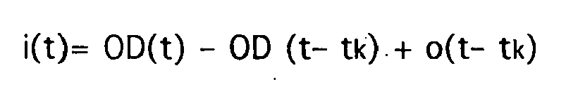
Hat t den Endwert t2 dagegen überschritten, so wird im nächsten Schritt geprüft, ob die erhaltenen Funktionsverläufe der Zuflußfunktion i(t) und der Abflußfunktion o(t) plausibel sind. Als Plausibilitätskriterium (d.h. Abbruchkriterium der Iteration) kann dienen, daß weder die Zuflußfunktion i(t) noch die Abflußfunktion o(t) Werte kleiner einem Schwellenwert aufweisen. Dieser Schwellenwert ist geeigneterweise größer oder gleich 0 zu wählen. Ferner kann das Plausibilitätskriterium beinhalten, daß die Zuflußfunktion i(t) als Summe einer endlichen Zahl von Funktionen darstellbar ist, welche der Form der Transportfunktion g(t) ähnlich sind.On the other hand, if t has exceeded the final value t 2 , then in the next step it is checked whether the obtained function curves of the inflow function i (t) and the outflow function o (t) are plausible. As a plausibility criterion (ie termination criterion of the iteration) it can serve that neither the inflow function i (t) nor the outflow function o (t) have values smaller than a threshold value. This threshold is appropriate greater than or equal to 0. Furthermore, the plausibility criterion may include that the inflow function i (t) can be represented as the sum of a finite number of functions which are similar to the form of the transport function g (t).
Sind die Funktionsverläufe der Zuflußfunktion i(t) und der Abflußfunktion o(t) nicht plausibel, so wird die mittlere Transitzeit mtt durch geeignete Erhöhung oder Erniedrigung um ein Inkrement angepaßt und ein weiterer Iterationsschritt ausgeführt, welcher wiederum mit dem Initialisierungsschritt beginnt und wie dargestellt abläuft.If the functional curves of the inflow function i (t) and the outflow function o (t) are not plausible, then the average transit time mtt is adjusted by an increment or decrement by one increment and another iteration step is performed, which in turn begins with the initialization step and proceeds as shown ,
Sind die Funktionsverläufe der Zuflußfunktion i(t) und der Abflußfunktion o(t) dagegen plausibel, so wird die Iteration abgebrochen und mit dem erhaltenen Funktionsverlauf von i(t) sowie dem erhaltenen Wert der mittlere Transitzeit mtt weiter verfahren, wie unten beschrieben.On the other hand, if the functional curves of the inflow function i (t) and the outflow function o (t) are plausible, the iteration is aborted and the function curve of i (t) obtained and the mean transit time mtt obtained are continued as described below.
Ebenfalls aus dem nicht-pulsatilen Anteil des Zeitverlaufs der optischen Dichte OD wird die Indikatorkonzentration im Gewebe bestimmt, wie im rechten Ast des in Fig. 2 abgebildeten Schemas dargestellt. Hierfür wird in einem Intervall von t1>0 bis t2 der nicht-pulsatile Anteil des Zeitverlaufs der optischen Dichte OD mittels Regression durch eine Exponentialfunktion nachgebildet und diese bis zum Zeitpunkt t=0 rückextrapoliert. Der Zeitpunkt t2 ist so gewählt, daß eine vollständige Durchmischung des Indikators mit dem Blut gewährleistet ist, d.h. kein auf Rezirkulation beruhender Konzentrations-Peak mehr feststellbar ist. Ferner wird der Wert des nicht-pulsatilen Anteils im Bereich t<0, d.h. OD(t<0) bestimmt.Also from the non-pulsatile portion of the time course of the optical density OD, the indicator concentration is determined in the tissue, as shown in the right branch of the scheme shown in Fig. 2. For this purpose, in an interval from t 1 > 0 to t 2, the non-pulsatile component of the time curve of the optical density OD is simulated by regression by an exponential function and this is back-extrapolated up to the time t = 0. The time t2 is chosen so that a complete mixing of the indicator is ensured with the blood, ie no recirculation-based concentration peak is more detectable. Furthermore, the value of the non-pulsatile component is determined in the range t <0, ie OD (t <0).
In einem nächsten Schritt erfolgt die eigentliche Berechnung der auf das Gewebe bezogenen Indikatorkonzentration unmittelbar nach der Indikatorinjektion CGewebe nach der Formel![]()
![]()
Zur Berücksichtigung des pulsatilen Anteils implementierte Auswertungsschritte sind in dem mittleren Ast der Figur 2 aufgeführt. An den pulsatilen Anteil des Zeitverlaufs der optischen Dichte OD wird eine Hüllkurve angepaßt. Ferner wird die Amplitude AOD(t<0), das heißt die Amplitude des pulsatilen Anteils der optischen Dichte für t<0 bestimmt.Evaluation steps implemented to take account of the pulsatile fraction are listed in the middle branch of FIG. An envelope is adapted to the pulsatile portion of the time course of the optical density OD. Further, the amplitude AOD (t <0), that is, the amplitude of the pulsatile portion of the optical density for t <0 is determined.
Mit aus dem pulsatilen Signalanteil gewonnenen absoluten Werten aus einem Bereich, in welchem die Amplitude groß und daher weniger anfällig gegen Verrauschen ist (beispielsweise für t von 0 bis 60s), wird die zuvor iterativ ermittelte Zuflußfunktion i(t) skaliert, etwa durch Minimierung der Summe der Differenzquadrate [i(t)- AOD(t)]2. Dies führt letztlich zu einer höheren Genauigkeit, denn während aus direkter Messung gewonnene Werte für größere t aufgrund geringerer Indikatorkonzentrationen zunehmend verrauscht sind, beschreibt i(t) die Abnahme der Indikatorkonzentration im Blut auch für große t gut.With absolute values obtained from the pulsatile signal portion from a range in which the amplitude is large and therefore less susceptible to noise (for example, for t from 0 to 60s), the previously iteratively determined inflow function i (t) is scaled, such as by minimizing the Sum of difference squares [i (t) -AOD (t)] 2 . This ultimately leads to a higher accuracy, because while values obtained from direct measurement are increasingly noisy for larger t due to lower indicator concentrations, i (t) describes the decrease of the indicator concentration in the blood well even for large t.
Ausgehend von einem Zeitintervall von t1a>0 bis t2a, in welchem sich der Indikator bereits gut im System verteilt hat (d.h. mit hinreichend großen t1a und t2a), wird die skalierte Zuflußfunktion i(t) bis zum Zeitpunkt t=0 rückextrapoliert (beispielsweise mittels einer durch Regression im Intervall t1a>0 bis t2 nachgebildete Exponentialfunktion).Starting from a time interval from t 1a > 0 to t 2a , in which the indicator has already been well distributed in the system (ie with sufficiently large t 1a and t 2a ), the scaled inflow function i (t) until the time t = 0 back-extrapolated (for example by means of an exponential function modeled by regression in the interval t 1a > 0 to t 2 ).
Die für die Berechnung des cerebralen Blutflusses CBV benötigte Indikatorkonzentration im Blut CBlut wird nach folgender Formel berechnet, worin AOD(t―>0) dem aus der rückextrapolierten Funktion gewonnenen Wert der Amplitude der optischen Dichte für t gegen 0 entspricht (welcher gegenüber einem durch direkte Messung bestimmten Wert weniger stark von der Schärfe des ersten Signalpeaks nach Indikatorgabe abhängt): 
Darin ist αICG der Absorptionskoeffizient des Indikators, αHb der Absorptionskoeffizient des Hämoglobins und CHb die Hämoglobinkonzentration im Blut.Where α ICG is the absorption coefficient of the indicator, α Hb is the absorption coefficient of hemoglobin and C Hb is the hemoglobin concentration in the blood.
Das cerebrale Blutvolumen CBV wird als Quotient aus der Indikatorkonzentration im Blut CBlut und der auf das cerebrale Gewebe bezogenen Indikatorkonzentration CGewebe berechnet, d.h.:
Der cerebrale Blutfluß CBF wird als Quotient aus dem cerebrale Blutvolumen CBV und der mittleren Transitzeit mtt, also nach der Formel![]()
![]()
Claims (12)
- Device for measuring the blood flow in an organ using an injected indicator, having a radiation source for emitting near infrared radiation into tissue of the organ at a first location, a sensor (2, 3) for detecting a proportion of the emitted near infrared radiation that exits from the tissue of the organ at a second site, and an evaluation unit (4) that detects the proportion of the emitted near infrared radiation that exits from the tissue of the organ as an input signal, which is composed of a pulsatile component and a non-pulsatile component, characterised in that the evaluation unit (4) is programmed to carry out the following evaluation steps:(a) determination of the injected indicator concentration based on the organ tissue from the non-pulsatile component of the input signal,(b) iterative determination of an inflow function i(t) that characterises the blood flow through the organ by variation of a mean transit time mtt until a stop criterion is reached,(c) determination of the injected indicator concentration based on the blood volume in the organ from the pulsatile component of the input signal and the iteratively determined inflow function i(t),(d) calculation of the blood volume in the organ as a quotient of the injected indicator concentration based on the organ tissue and the injected indicator concentration based on the blood volume in the organ, and(e) calculation of the blood flow in the organ as a quotient of the blood volume in the organ and the mean transit time mtt when the stop criterion has been reached.
- Device according to claim 1, wherein a scaling of the inflow function i(t) is provided by means of values determined from the pulsatile component of the input signal.
- Device according to claim 2, wherein the determination of the injected indicator concentration based on the blood volume in the organ comprises a back-extrapolation of the scaled inflow function i(t) to the injection time of the indicator.
- Device according to any one of the preceding claims, wherein during the iterative determination of the inflow function i(t), each iteration step comprises a step-by-step calculation by approximation of the inflow function i(t) according to the equation


wherein d/dt (Ctissue(t)) is a term, which describes the change in the injected indicator concentration based on the organ tissue, the value of the outflow function o(t) at the time t-tk is to be inserted for o(t-tk), and g(t) is a characteristic transport function, in which the mean transit time mtt is included. - Device according to any one of the preceding claims, wherein the stop criterion for the iterative determination of the inflow function i(t) includes that the minimum of the iteratively determined inflow function i(t) is greater than a threshold value.
- Device according to claim 2, wherein the threshold value is 0.
- Device according to any one of the preceding claims, wherein the stop criterion for the iterative determination of the inflow function i(t) includes that the inflow function i(t) can be represented as a sum of a finite number of functions which are similar to the form of the transport function g(t).
- Device according to any one of the preceding claims, wherein an absorption coefficient of the indicator that decreases with an increasing indicator concentration is stated for the determination of the injected indicator concentration based on the blood volume in the organ.
- Device according to any one of the preceding claims, wherein the device is equipped for the non-invasive measurement of the blood flow of the organ and has means for radiating the near infrared radiation in through the skin at the first location and means for capturing the exiting proportion of the emitted near infrared radiation through the skin at the second location.
- Device according to claim 9, wherein the device also has means for local reduction of blood circulation through the skin at the first location and the second location by applying a locally increased contact pressure.
- Device according to any one of the preceding claims, wherein the programming of the evaluation unit takes into account that the organ is the brain, the blood flow is cerebral blood flow CBF, and the blood volume is the cerebral blood volume CBV.
- Device according to any one of the preceding claims, wherein the indicator is indocyaningreen.
Applications Claiming Priority (2)
| Application Number | Priority Date | Filing Date | Title |
|---|---|---|---|
| DE10315574A DE10315574A1 (en) | 2003-04-05 | 2003-04-05 | Device for determining blood flow in an organ |
| DE10315574 | 2003-04-05 |
Publications (2)
| Publication Number | Publication Date |
|---|---|
| EP1464276A1 EP1464276A1 (en) | 2004-10-06 |
| EP1464276B1 true EP1464276B1 (en) | 2007-02-14 |
Family
ID=32842274
Family Applications (1)
| Application Number | Title | Priority Date | Filing Date |
|---|---|---|---|
| EP04101074A Expired - Lifetime EP1464276B1 (en) | 2003-04-05 | 2004-03-16 | Device for measuring blood flow in an organ |
Country Status (4)
| Country | Link |
|---|---|
| US (1) | US7529576B2 (en) |
| EP (1) | EP1464276B1 (en) |
| DE (2) | DE10315574A1 (en) |
| ES (1) | ES2281753T3 (en) |
Families Citing this family (6)
| Publication number | Priority date | Publication date | Assignee | Title |
|---|---|---|---|---|
| US7847547B2 (en) * | 2008-01-30 | 2010-12-07 | Wisconsin Alumni Research Foundation | Method and system for determining compound concentrations in a mixture using regression of NMR intensity peak values |
| CH699338B1 (en) | 2008-08-06 | 2012-01-13 | Carag Ag | Device for measuring the blood flow in a body tissue. |
| US8144958B2 (en) | 2008-09-11 | 2012-03-27 | Carl Zeiss Meditec Ag | Medical systems and methods |
| CN102525422B (en) * | 2011-12-26 | 2014-04-02 | 哈尔滨工业大学 | Brain function signal extracting method based on empirical mode decomposition optimization algorithm of multi-range measurement method |
| JP6861168B2 (en) | 2015-05-29 | 2021-04-21 | カラク アーゲー | Catheter for measuring blood flow in living tissue |
| WO2023016636A1 (en) * | 2021-08-11 | 2023-02-16 | Luciole Medical AG | Methods and apparatus for measuring absolute concentration values of components, blood flow and blood volume in a tissue |
Family Cites Families (20)
| Publication number | Priority date | Publication date | Assignee | Title |
|---|---|---|---|---|
| US4281645A (en) * | 1977-06-28 | 1981-08-04 | Duke University, Inc. | Method and apparatus for monitoring metabolism in body organs |
| US4805623A (en) * | 1987-09-04 | 1989-02-21 | Vander Corporation | Spectrophotometric method for quantitatively determining the concentration of a dilute component in a light- or other radiation-scattering environment |
| EP0615723A1 (en) * | 1993-03-04 | 1994-09-21 | Hamamatsu Photonics K.K. | Method and apparatus for measuring blood flow |
| JP3260472B2 (en) | 1993-03-26 | 2002-02-25 | 浜松ホトニクス株式会社 | Diagnostic device |
| JP3275159B2 (en) * | 1993-12-17 | 2002-04-15 | 日本光電工業株式会社 | Circulating blood volume measurement device |
| US5527822A (en) * | 1993-12-29 | 1996-06-18 | Forest Laboratories, Inc. | Method of treatment of traumatic brain injury |
| DE19635038A1 (en) * | 1996-08-29 | 1998-03-12 | Pulsion Verwaltungs Gmbh & Co | Method for the non-invasive determination of cerebral blood flow by means of near infrared spectroscopy |
| US7191110B1 (en) * | 1998-02-03 | 2007-03-13 | University Of Illinois, Board Of Trustees | Patient specific circulation model |
| US6167297A (en) * | 1999-05-05 | 2000-12-26 | Benaron; David A. | Detecting, localizing, and targeting internal sites in vivo using optical contrast agents |
| US6216021B1 (en) * | 1999-06-04 | 2001-04-10 | The Board Of Trustees Of The University Of Illinois | Method for measuring absolute saturation of time-varying and other hemoglobin compartments |
| US6339714B1 (en) * | 1999-09-13 | 2002-01-15 | Bo Chen | Apparatus and method for measuring concentrations of a dye in a living organism |
| US6516214B1 (en) * | 2000-01-24 | 2003-02-04 | The General Hospital Corporation | Detection of stroke events using diffuse optical tomography |
| AU2001234590A1 (en) * | 2000-01-28 | 2001-08-07 | The General Hospital Corporation | Fetal pulse oximetry |
| JP3718500B2 (en) * | 2000-07-21 | 2005-11-24 | ウニヴェルシュタート チューリッヒ | Probe and apparatus for measuring brain hemodynamics and oxygen treatment |
| US6606509B2 (en) * | 2001-03-16 | 2003-08-12 | Nellcor Puritan Bennett Incorporated | Method and apparatus for improving the accuracy of noninvasive hematocrit measurements |
| DE10120980B4 (en) * | 2001-05-01 | 2009-12-03 | Pulsion Medical Systems Ag | A method, apparatus and computer program for determining blood flow in a tissue or organ region |
| US6802812B1 (en) * | 2001-07-27 | 2004-10-12 | Nostix Llc | Noninvasive optical sensor for measuring near infrared light absorbing analytes |
| US6709402B2 (en) * | 2002-02-22 | 2004-03-23 | Datex-Ohmeda, Inc. | Apparatus and method for monitoring respiration with a pulse oximeter |
| US7024234B2 (en) * | 2002-09-20 | 2006-04-04 | Lyle Aaron Margulies | Method and apparatus for monitoring the autonomic nervous system |
| CA2550417A1 (en) * | 2005-12-22 | 2007-06-22 | Institut De Cardiologie De Montreal | Method for maintaining cerebral hemispheric oxygen saturation during surgery |
-
2003
- 2003-04-05 DE DE10315574A patent/DE10315574A1/en not_active Withdrawn
-
2004
- 2004-03-16 EP EP04101074A patent/EP1464276B1/en not_active Expired - Lifetime
- 2004-03-16 ES ES04101074T patent/ES2281753T3/en not_active Expired - Lifetime
- 2004-03-16 DE DE502004002877T patent/DE502004002877D1/en not_active Expired - Lifetime
- 2004-04-01 US US10/816,306 patent/US7529576B2/en active Active
Also Published As
| Publication number | Publication date |
|---|---|
| US7529576B2 (en) | 2009-05-05 |
| US20040249275A1 (en) | 2004-12-09 |
| DE502004002877D1 (en) | 2007-03-29 |
| DE10315574A1 (en) | 2004-10-28 |
| ES2281753T3 (en) | 2007-10-01 |
| EP1464276A1 (en) | 2004-10-06 |
Similar Documents
| Publication | Publication Date | Title |
|---|---|---|
| DE69727776T2 (en) | METHOD FOR DETERMINING THE FRACTIONAL OXYGEN SATURATION | |
| EP0914601B1 (en) | Method of non-invasive determination of oxygen saturation in tissue in which blood is circulating | |
| EP0928156B1 (en) | Device for non-invasively determining cerebral blood flow by near-infrared spectroscopy | |
| DE102005007574B3 (en) | catheter device | |
| DE69725621T2 (en) | METHOD AND DEVICE FOR ADAPTIVE AVERAGE VALUING OF DATA SIGNALS | |
| DE69934888T2 (en) | NON-INVASIVE OPTICAL MEASUREMENT OF A BLOOD COMPONENT | |
| DE69928569T2 (en) | COMPUTER FOR DETECTING PLETHYSMOGRAPHIC PULSES | |
| EP1813188B1 (en) | System for providing a dilution measuring point | |
| DE60315596T2 (en) | VENOUS PULSE OXIMETRY | |
| DE69333456T2 (en) | SYSTEM METHOD FOR NON-INVASIVE MONITORING OF HEMATOCRIT VALUE | |
| DE60032128T2 (en) | DEVICE FOR QUALITY AND ACCURACY INDICATION OF PHYSIOLOGICAL MEASUREMENTS | |
| EP1290976A2 (en) | System and software for determining cardiovascular parameters | |
| EP2999402B1 (en) | Measurement system and method for measuring parameters in a body tissue | |
| EP0505918A1 (en) | Apparatus and method for determining heart minute volumes | |
| WO1996016594A2 (en) | Process and device for determining cerebral blood flow and intracerebral blood volume | |
| DE102006039957A1 (en) | Method for evaluating heart rate variability | |
| EP1464276B1 (en) | Device for measuring blood flow in an organ | |
| DE4130931C2 (en) | Method and device for determining the circulating blood volume | |
| WO2000071025A1 (en) | Method and device for measuring the degree of organization of water in human and animal bodies | |
| WO2009013287A1 (en) | Method for determination of a quasi-continuous blood pressure change in a pulsatile blood stream | |
| EP2609854B1 (en) | Movement correlated method and optoelectronic device for non-invasive determination of the dermal venous oxygen supply to peripheral areas of the leg | |
| AT501013B1 (en) | DEVICE AND METHOD FOR MEASURING INDICATOR CONCENTRATION AND APPARATECLEARANCE IN EXTRACORPORAL BLOOD TREATMENT PROCEDURES | |
| DE102011085503B4 (en) | Control unit and medical examination device | |
| DE102020129899A1 (en) | Medical system for determining a cardiac output-dependent parameter | |
| AT512393B1 (en) | Method for processing images of the pulmonary circulation and apparatus for carrying out this method |
Legal Events
| Date | Code | Title | Description |
|---|---|---|---|
| PUAI | Public reference made under article 153(3) epc to a published international application that has entered the european phase |
Free format text: ORIGINAL CODE: 0009012 |
|
| AK | Designated contracting states |
Kind code of ref document: A1 Designated state(s): AT BE BG CH CY CZ DE DK EE ES FI FR GB GR HU IE IT LI LU MC NL PL PT RO SE SI SK TR |
|
| AX | Request for extension of the european patent |
Extension state: AL LT LV MK |
|
| 17P | Request for examination filed |
Effective date: 20050315 |
|
| AKX | Designation fees paid |
Designated state(s): DE ES FR GB IT |
|
| GRAP | Despatch of communication of intention to grant a patent |
Free format text: ORIGINAL CODE: EPIDOSNIGR1 |
|
| GRAS | Grant fee paid |
Free format text: ORIGINAL CODE: EPIDOSNIGR3 |
|
| GRAA | (expected) grant |
Free format text: ORIGINAL CODE: 0009210 |
|
| AK | Designated contracting states |
Kind code of ref document: B1 Designated state(s): DE ES FR GB IT |
|
| REG | Reference to a national code |
Ref country code: GB Ref legal event code: FG4D Free format text: NOT ENGLISH |
|
| REF | Corresponds to: |
Ref document number: 502004002877 Country of ref document: DE Date of ref document: 20070329 Kind code of ref document: P |
|
| GBT | Gb: translation of ep patent filed (gb section 77(6)(a)/1977) |
Effective date: 20070502 |
|
| ET | Fr: translation filed | ||
| REG | Reference to a national code |
Ref country code: ES Ref legal event code: FG2A Ref document number: 2281753 Country of ref document: ES Kind code of ref document: T3 |
|
| PLBE | No opposition filed within time limit |
Free format text: ORIGINAL CODE: 0009261 |
|
| STAA | Information on the status of an ep patent application or granted ep patent |
Free format text: STATUS: NO OPPOSITION FILED WITHIN TIME LIMIT |
|
| 26N | No opposition filed |
Effective date: 20071115 |
|
| PGFP | Annual fee paid to national office [announced via postgrant information from national office to epo] |
Ref country code: ES Payment date: 20100324 Year of fee payment: 7 |
|
| PGFP | Annual fee paid to national office [announced via postgrant information from national office to epo] |
Ref country code: IT Payment date: 20100325 Year of fee payment: 7 |
|
| PG25 | Lapsed in a contracting state [announced via postgrant information from national office to epo] |
Ref country code: IT Free format text: LAPSE BECAUSE OF NON-PAYMENT OF DUE FEES Effective date: 20110316 |
|
| REG | Reference to a national code |
Ref country code: ES Ref legal event code: FD2A Effective date: 20120509 |
|
| PG25 | Lapsed in a contracting state [announced via postgrant information from national office to epo] |
Ref country code: ES Free format text: LAPSE BECAUSE OF NON-PAYMENT OF DUE FEES Effective date: 20110317 |
|
| REG | Reference to a national code |
Ref country code: FR Ref legal event code: PLFP Year of fee payment: 13 |
|
| REG | Reference to a national code |
Ref country code: FR Ref legal event code: PLFP Year of fee payment: 14 |
|
| REG | Reference to a national code |
Ref country code: FR Ref legal event code: PLFP Year of fee payment: 15 |
|
| PGFP | Annual fee paid to national office [announced via postgrant information from national office to epo] |
Ref country code: FR Payment date: 20230321 Year of fee payment: 20 |
|
| PGFP | Annual fee paid to national office [announced via postgrant information from national office to epo] |
Ref country code: GB Payment date: 20230321 Year of fee payment: 20 Ref country code: DE Payment date: 20230321 Year of fee payment: 20 |
|
| P01 | Opt-out of the competence of the unified patent court (upc) registered |
Effective date: 20230512 |
|
| REG | Reference to a national code |
Ref country code: DE Ref legal event code: R071 Ref document number: 502004002877 Country of ref document: DE |
|
| REG | Reference to a national code |
Ref country code: GB Ref legal event code: PE20 Expiry date: 20240315 |