EP1464270A1 - Towing positioning device - Google Patents
Towing positioning device Download PDFInfo
- Publication number
- EP1464270A1 EP1464270A1 EP03741413A EP03741413A EP1464270A1 EP 1464270 A1 EP1464270 A1 EP 1464270A1 EP 03741413 A EP03741413 A EP 03741413A EP 03741413 A EP03741413 A EP 03741413A EP 1464270 A1 EP1464270 A1 EP 1464270A1
- Authority
- EP
- European Patent Office
- Prior art keywords
- unit
- hauling
- signal
- control signal
- control unit
- Prior art date
- Legal status (The legal status is an assumption and is not a legal conclusion. Google has not performed a legal analysis and makes no representation as to the accuracy of the status listed.)
- Granted
Links
Images












Classifications
-
- A—HUMAN NECESSITIES
- A61—MEDICAL OR VETERINARY SCIENCE; HYGIENE
- A61B—DIAGNOSIS; SURGERY; IDENTIFICATION
- A61B1/00—Instruments for performing medical examinations of the interior of cavities or tubes of the body by visual or photographical inspection, e.g. endoscopes; Illuminating arrangements therefor
- A61B1/005—Flexible endoscopes
- A61B1/0051—Flexible endoscopes with controlled bending of insertion part
-
- A—HUMAN NECESSITIES
- A61—MEDICAL OR VETERINARY SCIENCE; HYGIENE
- A61B—DIAGNOSIS; SURGERY; IDENTIFICATION
- A61B1/00—Instruments for performing medical examinations of the interior of cavities or tubes of the body by visual or photographical inspection, e.g. endoscopes; Illuminating arrangements therefor
- A61B1/00147—Holding or positioning arrangements
- A61B1/0016—Holding or positioning arrangements using motor drive units
-
- A—HUMAN NECESSITIES
- A61—MEDICAL OR VETERINARY SCIENCE; HYGIENE
- A61B—DIAGNOSIS; SURGERY; IDENTIFICATION
- A61B1/00—Instruments for performing medical examinations of the interior of cavities or tubes of the body by visual or photographical inspection, e.g. endoscopes; Illuminating arrangements therefor
- A61B1/005—Flexible endoscopes
- A61B1/009—Flexible endoscopes with bending or curvature detection of the insertion part
Definitions
- the present invention relates to an apparatus for traction positional control, and more particularly, to an apparatus for traction positional control that bends or rotates a part of a motorized traction mechanism such as a motorized endoscope or a robot arm by hauling a traction member such as a wire.
- a motorized traction mechanism for hauling a traction member such as a wire by operating a driving unit such as a motor, as in a motorized endoscope or a robot arm, to bend or rotate a distal tip is widely known. Since the motorized traction mechanism can be provided in such a manner that a generally large and heavy driving unit is separated from the distal tip via the traction member, there is a merit that the distal tip can be reduced in size and weight.
- a conventional endoscope that controls the slack of the wire is disclosed in, for example, Japanese Patent Application Laid-open No. 2000-300511.
- the conventional endoscope includes a flexible tube, a wire disposed in the flexible tube, a driving unit that drives the wire to for bend the flexible tube, a displacement detecting unit that detects a displacement from a reference position of the wire, a displacement direction detecting unit that detects a displacement direction of the wire, and a slack control unit that controls the slack of the wire based on outputs of the displacement detecting unit and the displacement direction detecting unit.
- the conventional endoscope further includes a tension detecting unit that detects tension of the wire, and the slack control unit controls the slack of the wire based on outputs of the tension detecting unit, the displacement detecting unit and the displacement direction detecting unit.
- a state of the slack is estimated based on displacement information and displacement direction information, and tension of wire detected by the tension detecting unit.
- the above publication discloses, as a concrete method for controlling the slack, that when the driving unit is driven to bend the flexible tube from an initial state (neutral reference position) in which both wire do not have the slack and any portion is not bent, one of the wire that is pushed out becomes loose, and when the driving unit is inverted and driven, assuming that the flexible tube can not be straightly bent by the loosened wire, a driving speed of the driving unit after the inversion is accelerated immediately after the inversion, and the speed is returned to the normal speed later.
- a distal bending section of an endoscope when operated, as described in Japanese Patent Publication No. S63-59329, a wire that is connected to the distal bending section is hauled by a driving force of an electric motor, thereby bending the distal bending section in vertical/lateral direction.
- a voltage is applied to the motor in proportion to an operation amount of an operating lever provided on an operating section.
- a bending angle of the distal bending section can be set.
- the operation amount is determined based on a distortion gage mounted on the operating lever, and the voltage is directly applied to the motor in accordance with the operation amount. Therefore, although the electric motor can be driven in proportion to the operation amount of the operating lever, friction between the wire and an inner surface of a coil sheath for guiding the wire, and a slack of the wire are not sufficiently taken into account, the operation amount and a bending amount of the distal bending section do not correspond to each other, which is not sufficient for enhancing the operability of an observer (operator of the endoscope).
- Japanese Patent Application Laid-open No. H6-22904 describes a technique in which a hauling wire is mounted to a distal bending section of an endoscope inserting portion, the hauling wire is allowed to pass through a universal cord through a relay pulley provided on the operating section, and the hauling wire is hauled by a driving force of the electric motor. It also discloses a technique in which a rotation angle of the pulley and a rotation angle of the electric motor are compared with each other, a loose state of the hauling wire is detected, and when the hauling wire is in a loosened state, the electric motor is driven at a maximum speed, and the slack of the hauling wire is instantaneously resolved.
- the slack of wire generated in the universal cord between the motor and the relay pulley can be resolved, but slack and friction generated in the hauling wire of the endoscope inserting portion from the relay pulley are not taken into account, and a situation when the relay pulley does not exist is not taken into account, either.
- the present invention provides an apparatus for traction positional control comprising a hauling unit which hauls a subject to be operated and which bends or rotates the subject, the subject having a towed mechanism which is formed such that the towed mechanism can be bent or rotated, a driving unit which generates a driving force for the hauling unit, and a control unit which outputs, to the driving unit, a control signal for controlling the hauling unit to drive by the driving unit, the control signal corresponding to a target value which is input by an operating unit, wherein the control unit increases a variation amount of the control signal which is output in a predetermined range including a position of the hauling unit in a state before the hauling unit hauls greater than a variation amount of the control signal which is output in a range other than the predetermined range.
- the operation command value signal is compensated by the feedforward control unit, and the hauling unit is driven with a driving force corresponding to a drive signal generated based on the feedforward control signal generated by the feedforward control unit. Therefore, even if delay caused by driving operation of the hauling unit is generated at the time of hauling, since the delay is compensated by the feedforward control unit, it is possible to allow the bending position that is to be operated to instantaneously follow the operation command value, and to enhance the operability.
- a displacement (position of wire) caused by hauling of the hauling unit which is attenuated by friction or slack is detected as hauling property of the hauling unit, the hauling property is fed back, a feedback control signal is generated based on the deviation between the hauling property detecting signal and the operation command value signal, and the feedforward control signal is corrected using the feedback signal.
- a motorized endoscope of a first embodiment of the present invention will be explained with reference to Fig. 1 to Fig. 5.
- This motorized endoscope comprises a distal bending section 2 that can be bent and is a towed mechanism, wires 4 and 5 that are hauling units for hauling and bend the distal bending section 2 from both directions, a motor 9 that is driving unit that generates a driving force to the wires 4 and 5 in accordance with a control signal, a rotary encoder 14 that is a position detecting unit that detects a position of the motor 9, a joystick 10 that is an operating unit that inputs a target value, and a control device 11 that is a control unit that outputs a control signal that corresponds to the target value by the joystick 10 and that is based on a detected position detected by the rotary encoder 14.
- An inserting portion 1 is formed into a thin and long shape so that the inserting portion 1 can be inserted into a body cavity or a pipe.
- the inserting portion 1 is provided at its distal end with the distal bending section 2, the wires 4 and 5 for bending the distal bending section 2 vertically and laterally, and coil sheaths 6 and 7 for protecting the wires 4 and 5.
- a pulley 8, the motor 9 and the control device 11 are provided outside the inserting portion 1.
- the distal bending section 2 is a hose comprising a plurality of articulation wheels 3 that are rotatably connected to one another.
- Fig. 1 illustrates a state in which the distal bending section 2 is bent in the vertical direction.
- the distal bending section 2 has such characteristics that when a tension caused by the wires 4 and 5 is weakened from a state in which the distal bending section 2 is bent, the distal bending section 2 tries to restore to its original state to some degrees.
- the distal bending section 2 is provided at its distal end with one distal ends of the wires 4 and 5.
- the two wires 4 and 5 are made of flexible material, the wires 4 and 5 pass through the coil sheaths 6 and 7, and the other ends of the wires 4 and 5 are wound around the pulley 8 from opposite directions and fixed.
- the pulley 8 is connected to the motor 9 through a gear or the like (not illustrated), and constitutes a portion of the driving unit. That is, if the motor 9 is driven to rotate the pulley 8, the one wire 4 wound around the pulley 8 is pulled, and the other wire 5 is sent out. With this, the distal bending section 2 is bent upward.
- Fig. 1 only illustrates a device for vertically bend the distal bending section 2 for simplifying the drawing. Since structure, operation and effect of wires, coil sheaths, a pulley, a motor and a control device for laterally bending the distal bending section 2 are basically the same as those of the device that vertically bends the distal bending section 2, these elements are omitted. Further, although it is not illustrated in the drawings, the inserting portion comprising a distal bending section, wire and coil sheaths are protected by a thin and long elastic pipe or the like.
- the inserting portion 1 is usually provided at its leading end with a charge coupled device (CCD) (not illustrated) or the like, and with a monitor (not illustrated) on which an image of an organ in a body cavity or an interior of the pipe is displayed.
- CCD charge coupled device
- monitor not illustrated
- An operator vertically and laterally bends and operates the distal bending section 2 by means of the joystick 10 while seeing an image displayed on the monitor. Therefore, if an operation amount of the joystick 10 and a bend angle of the distal bending section 2 coincide with each other, the operability is enhanced.
- the control device 11 outputs a control signal for driving the motor 9 so that an operation amount of the joystick 10 is defined as a target value R, the target value R and the bend angle of the distal bending section 2 coincide with each other as close as possible.
- the control device 11 includes a correction table 12 having a previously prepared parameter, and a motor control unit 13 for driving the motor 9 based on a control signal Rmot that is output from the correction table 12.
- a rotary encoder 14 is mounted to the motor 9. An output of the rotary encoder 14 is detected by a motor position detector 15. A motor position signal Ymot is output from the motor position detector 15.
- the motor control unit 13 comprises a PID (proportion, integration, differentiation) that is a known technique.
- the control signal that is output from the motor control unit 13 is amplified by a motor amplifier 16 and is input to the motor 9.
- the motor 9 can follow the control signal Rmot substantially without delay.
- the distal bending section 2 is not bent until the motor 9 is rotated to a position where the slack of the wire in that direction is resolved.
- the correction table 12 is arranged such that the table compensates characteristics in a predetermined range of the neutral reference position.
- Fig. 2 illustrates characteristics of the correction table 12.
- An operation amount of the joystick 10 is defined as the target value R of the bend angle (position) of the distal bending section 2.
- the correction table 12 outputs a control signal Rmot in which a variation amount thereof with respect to the target value R becomes greater in the target value R including the neutral reference position where both the wires 4 and 5 become loose than a range other than the range of the target value R, and the correction table 12 swiftly rotates the motor 9 and swiftly resolves the slack of the wires.
- the lower limit value R1 and the upper limit value R2 are varied in accordance with degree of extension of the wires 4 and 5, but the lower limit value R1 and the upper limit value R2 may be set manually each time or may be set automatically by carrying out calibration at appropriate timing.
- the lower limit value R1 and the upper limit value R2 are set automatically by carrying out calibration, it is necessary to mount tension sensor to the wires 4 and 5 to measure the slack of the wire.
- the target value R is automatically generated to bend the motorized endoscope, the slack of the wire is measured, a range of the target value R at which slack is generated in both the wires 4 and 5 is checked, and the lower limit value R1 and the upper limit value R2 are set.
- the range of the target value R including the neutral reference position where slack is generated in both the wires 4 and 5 varies depending upon shape of the inserting portion 1, speed of the distal bending section 2 and the like.
- the lower limit value R1 and the upper limit value R2 can not completely coincide with the range of the target value R at which both the wires 4 and 5 actually become loose. If the target ranges R1 to R2 are smaller than an actual range, the compensation of the slack of the wire is insufficient, and if the target ranges R1 to R2 are greater than the actual range, speed of the distal bending section at a portion of the wire that is not loosened becomes excessively high in some cases.
- the lower limit value R1 and the upper limit value R2 are adjusted such that the operability is optimized while taking characteristics of the lower limit value R1 and the upper limit value R2 into account.
- An output of the correction table 12 need not be used as the control signal Rmot as it is, and the output may be allowed to pass through a notch filter or a low pass filter and then may be used as the control signal Rmot so that a differentiated value of the control signal Rmot is not abruptly varied.
- the correction table 12 has such characteristics that a variation amount of the control signal Rmot with respect to the target value R is continuously and smoothly varies from 1 to a as illustrated in Fig. 3.
- FIG. 4 illustrates one example of a result of experiment when the correction table 12 illustrated in Fig. 1 is not used.
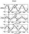
- Fig. 5 illustrates one example of a result of experiment when the correction table 12 illustrated in Fig. 1 is used.
- the triangular wave is given as a target value 100.
- the target value 100 and a motor position 101 are illustrated in upper graphs
- the target value 100 and tension 102 of the wires 4 and 5 are illustrated in intermediate graphs
- the target value 100 and time wave of a bend angle (direction of the distal end) 104 of the distal bending section 2 are illustrated in lower graphs.
- the tensions 102 of the wires 4 and 5 are always positive values
- a tension 102 of the wire 5 for bending the distal bending section downward is indicated with a negative value so that the graphs can easily be seen in correspondence with the bend angle 104.
- the bend angle 104 is indicated as zero when the distal bending section is not bent in any of upward and downward directions, as a positive value when the distal bending section is bent upward, and as a negative value when the distal bending section is bent downward.
- the target value 100 and the motor position 101 coincide with each other as apparent from the upper graph in Fig. 4, and it can be found that the motor 9 follows the control signal without delay.
- tensions 102 and 103 of both the wires 4 and 5 are zero in the vicinity of location where the target value 100 becomes zero, and both the wires 4 and 5 become loose.
- the bend angle 104 is not varies almost at all as apparent from the lower graph in Fig. 4, and it is found that the distal bending section 2 does not respond to the target value 100.
- a second embodiment of the present invention will be explained with reference to Fig. 6.
- the second embodiment is different from the first embodiment in the following description, and other portions of the second embodiment are basically the same as those of the first embodiment.
- the operation amount of the joystick 10 is defined as a target value R' of speed of the distal bending section 2. That is, an operator designates the speed of the distal bending section 2, and operates the apparatus.
- an integrator 17 is provided in front of the correction table 12, and a value to be input to the correction table 12 is defined as a target value R of position of the distal bending section 2 like the first embodiment.
- a differentiator 18 is provided behind the correction table 12, a control signal Rmot that is output from the correction table 12 is differentiated, and the resultant is defined as a speed control signal Rmot'.
- a motor speed detector 19 is provided instead of the motor position detector 15 illustrated in Fig. 1, so that a motor speed signal Ymot' can be obtained.
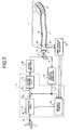
- a third embodiment of the present invention will be explained with reference to Fig. 7 and Fig. 8.
- the third embodiment is different from the first embodiment in the following description, and other portions of the third embodiment are basically the same as those of the first embodiment.
- ranges R1 to R2 of the target value R at which both the wires 4 and 5 become loose is automatically renewed.
- tension sensors 20 and 21 are mounted to the wires 4 and 5 as illustrated in Fig. 7, and a wire tension detector 22 detects tensions T1 and T2 (both tensions are zero or higher).
- the renewal unit 23 renews the lower limit value R1 and the upper limit value R2 using the motor position signal Ymot and the tensions T1 and T2 of the wires 4 and 5.
- the renewal unit 23 substitutes the current R into the lower limit value R1 or the upper limit value R2.
- step S1 when both T1 ⁇ T01 and T2 ⁇ T02 are established using small positive values T01 and T02, it may be judged that slack is generated in both the wires 4 and 5.
- step S2 it is judged whether a current motor position signal Ymot and a control signal Rmot when the lower limit value R1 and the upper limit value R2 are renewed are substantially the same so that the motor 9 is not abruptly driven by renewing the lower limit value R1 and the upper limit value R2. Because a control signal when the lower limit value R1 and the upper limit value R2 are renewed can be expressed as axR, it is judged whether
- a control signal only a short while ago may be used instead of the motor position signal Ymot in step S2.
- step S3 it is judged which one of the lower limit value R1 and the upper limit value R2 should be renewed. If a target value at which the distal bending section 2 is not bent in any of upward and downward directions is defined as zero, a range of a target value at which both the wires 4 and 5 become loose is R1 ⁇ 0 and R2>0 because the range straddles zero. Therefore, when R>0, a current R is assigned to the upper limit value R2, and otherwise, the current R is assigned to the lower limit value R1.
- the lower limit value R1 and the upper limit value R2 are renewed using these methods illustrated in Fig. 8.
- the upper limit value R2 may be also renewed to a value of -R1
- the upper limit value R1 may be also renewed to a value of -R2.
- a range of the target value R at which both the wires 4 and 5 become loose depends shape of the inserting portion and speed of the distal bending section, but if the third embodiment is used, the lower limit value R1 and the upper limit value R2 can be renewed. Therefore, it is possible to enhance the response of the distal bending section under a condition close to an actual using condition.
- a fourth embodiment of the present invention will be explained with reference to Fig. 9.
- the fourth embodiment is different from the third embodiment in the following description, and other portions of the third embodiment are basically the same as those of the third embodiment.
- the operation amount of the joystick 10 is defined as target value R' of speed of the distal bending section 2.
- an integrator 17 is provided in front of the correction table 12, and a value to be input to the correction table 12 is defined as a target value R of a position of the distal bending section 2 like the third embodiment.
- a differentiator 18 is provided behind the correction table 12, a control signal Rmot that is output from the correction table 12 is differentiated, and the resultant is defined as a speed control signal Rmot'.
- a motor speed detector 19 is provided instead of the motor position detector 15 illustrated in Fig.
- a fifth embodiment of the present invention will be explained with reference to Fig. 10.
- the fifth embodiment is different from the third embodiment in the following description, and other portions of the fifth embodiment are basically the same as those of the third embodiment.
- the correction table 12 is replaced by a differentiator 25, a variable gain 26 and an integrator 27, and the renewal unit 23 is replaced by a switching unit 28.
- the correction table 12 determines a control signal Rmot from the target value R of position, but the variable gain 26 in the fifth embodiment determines a speed control signal Rmot' from a target value R' of speed.
- the differentiator 25 differentiates the target value R of position that is output from the joystick 10, and outputs the target value R' of speed.
- the variable gain 26 multiplies the target value R' by k and outputs the resultant as speed control signal Rmot'.
- k is determined by the switching unit 28. If both the wires 4 and 5 become loose, the switching unit 28 sets k to a which is greater than 1, and if not, the switching unit 28 sets k to 1. It is judged whether both the wires 4 and 5 become loose by the same method as that of the third embodiment. That is, when T1+T2 ⁇ T0 is established or when both T1 ⁇ T01 and T2 ⁇ T02 are established, it is judged that both the wires 4 and 5 become loose.
- the integrator 27 integrates the speed control signal Rmot' and outputs a control signal Rmot.
- an output of the integrator 27 may be allowed to pass through a notch filter or a low pass filter and then the resultant may be used as the control signal Rmot, instead of using the output of the integrator 27 as the control signal Rmot as it is.
- the switching unit 28 may determine k such that k is continuously varied from 1 to a in accordance with tensions of the wires 4 and 5.
- a sixth embodiment of the present invention will be explained with reference to Fig. 11.
- the sixth embodiment is different from the fifth embodiment in the following description, and other portions of the sixth embodiment are basically the same as those of the fifth embodiment.
- an operation amount of the joystick 10 that is determined as the target value R of position of the distal bending section 2 in the fifth embodiment is determined as a target value R' of speed of the distal bending section 2.
- the differentiator 25 and the integrator 27 in Fig. 10 that illustrates the fifth embodiment become unnecessary.
- the switching unit 28 illustrated in Fig. 11 may judge whether the wire 4 or 5 becomes loose and may determine k while taking only the wire 4 or 5 that is to be bent into account, instead of judging whether both the wires 4 and 5 become loose. If k is increased when the wire 4 or 5 that is to be bent becomes loose, slack generated when a bending direction is switched can be compensated, and the response of the distal bending section at that time can be enhanced.
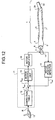
- a seventh embodiment of the present invention will be explained with reference to Fig. 12.
- the seventh embodiment is different from the first embodiment in the following description, and other portions of the seventh embodiment are basically the same as those of the fifth embodiment.
- the apparatus for traction positional control of the first embodiment is applied to a robot arm.
- the robot arm comprises a driven section 29 provided at a distal end of the robot arm, wires 4 and 5 for rotating the driven section 29, coil sheaths 6 and 7 for protecting the wires 4 and 5, and a pulley 8, a motor 9, a joystick 10 and a control device 11 that function as driving sections.
- a finger 30 is fixed to the driven section 29. If the driven section 29 is rotated, the finger 30 moves in the vertical direction.
- One distal ends of the wires 4 and 5 are wound around the driven section 29 from opposite sides and fixed thereto.
- the wires 4 and 5 pass through the coil sheaths 6 and 7, and the other ends of the wires 4 and 5 are wound around the pulley 8 from opposite sides and fixed thereto.
- the pulley 8 is connected to the motor 9 through a gear (not illustrated). If the motor 9 is driven to rotate the pulley 8, the driven section 29 rotates and the finger 30 moves.
- a portion between the driven section 29 and the pulley 8 need not be soft or flexible in some cases. In that case, the coil sheaths 6 and 7 are not always necessary.
- one more identical apparatus may be provided below the original apparatus, and the lower finger may grasp or release an object by moving the lower finger in an opposite manner from the upper finger.
- the joysticks 10 and the control devices 11 of the upper and lower apparatuses may be the same and the rotational directions of the pulleys 8 may be opposite from each other.
- the finger 30 may be provided at its distal end with a traction mechanism or other mechanism.
- the target value R may be generated automatically using a computer or the like instead of the joystick 10.
- the second embodiment to the sixth embodiment can also be applied to a robot arm.
- the apparatus for traction positional control of each of the first embodiment to the seventh embodiment even if both the hauling units become loose at the neutral reference position, the slack can be controlled at the neutral reference position and it is possible to position the towed mechanism swiftly and precisely.
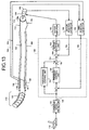
- Fig. 13 illustrates a block diagram of an apparatus for controlling traction of a motorized endoscope according to an eighth embodiment of the present invention.
- the motorized endoscope is provided with a joystick 110 mounted to the operating section and capable of moving in the vertical and lateral directions, a distal bending section 112 that can be bent, hauling wires 114 and 116 for bending a distal end of the distal bending section 112 in the vertical direction, a pulley 118 around which the hauling wires 114 and 116 are wound and the pulley 118 applying a hauling force, and a motor (electric motor) 120 connected to the pulley 118 through a gear mechanism for rotating the pulley 118.
- a motor electric motor
- the hauling wires 114 and 116 comprise one continuous wire and pass through coil sheaths 122 and 124 and are connected to the distal bending section 112.
- the distal bending section 112 is a to-be-operated subject that constitute a main element of the towed mechanism.
- the distal bending section 112 is a hose comprising a plurality of articulation wheels 126 that are rotatably connected to one another.
- the distal bending section 112 is formed into a substantially cylindrical shape, and can bend in the vertical and lateral directions.
- the distal bending section 112 bends in the vertical direction by hauling the hauling wires 114 and 116. More specifically, if the motor 120 is rotated normally or reversely and the pulley 118 is rotated, one of the hauling wires 114 and 116 is pulled, the other is sent out and the distal bending section 112 bent in the vertical direction. That is, the hauling wires 114 and 116 are hauling units that haul the distal bending section 112 that is to be operated by driving the motor 120.
- Fig. 13 only illustrates the pair of hauling wires 114 and 116 for vertically bending the distal bending section 112 for simplifying the drawing. Since the hauling wires, the pulley, the motor and the control device that are necessary to bending the distal bending section 112 in the lateral direction are the same as those used for vertically bending the distal bending section 112, illustration thereof is omitted.
- the distal bending section 112 and the coil sheaths 122 and 124 are inserted into and protected by inserting portions (not illustrated) comprising thin and long elastic pipes.
- a CCD camera (not illustrated) comprising CCD is mounted to a distal end of the distal bending section 112 that is a distal end of the inserting portion.
- the CCD camera is connected to a monitor (not illustrated) through a cable disposed in the inserting portion.
- An image of an organ in a body cavity or an industrial pipe is displayed on a screen of the monitor.
- an operator operates the joystick 110 to bend the distal bending section vertically or laterally using his or her left arm while seeing the image displayed on the screen of the monitor, and holds an intermediate portion of the inserting portion with his or her right arm to move the inserting portion forward and backward, and some times rotates the inserting portion to push the inserting portion into the body cavity, and after the distal end of the inserting portion reaches a portion to be observed, the operator bends the distal end of the distal bending section 112 to shoot the observing point in an appropriate state, and can carry out appropriate processing using a tool inserted into the inserting portion.
- the distal end side distal bending section 112 of the inserting portion is hauled by the hauling wires 114 and 116 in accordance with a driving force of the motor.
- degrees of the slack and friction between the hauling wires 114 and 116 and the coil sheaths 122 and 124 are varied by variation in friction between the hauling wires 114 and 116 and the coil sheaths 122 and 124, slack generated in the hauling wire that is not hauled by the pulley 118 (hauling wire that is sent out), and bending shape in the intermediate portion of the inserting portion. That is, if problems of friction, slack and variation in characteristics are not overcome, the bend position of the distal bending section 112 can not be allowed to follow the operation command value instantaneously.
- a control system including the feedforward control system and the feedback control system is constructed as follows:
- sensors 128 and 130 for observing the moving amounts of the hauling wires 114 and 116 are mounted to distal ends of the coil sheaths 122 and 124.
- the sensors 128 and 130 detect the moving amounts of the hauling wires 114 and 116 by means of an optical linear encoder, and a resistive linear potentiometer for example.
- positions of the hauling wires 114 and 116 detected by the sensors 128 and 130 are equal to a moving amount of a distal end of the distal bending section 112, i.e., the bend position.
- Wire position signals 132 and 134 detected by the sensors 128 and 130 are input to the wire position detector 136.
- the wire position signals 132 and 134 illustrate positive value when the hauling wires 114 and 116 move in the direction shown with arrows.
- the wire position detector 136 obtains the average of the sum of the wire position signals 132 and 134, and outputs the wire distal end position signal 138 in which the average value indicates a position of the distal end of the distal bending section 112.
- the sensors 128 and 130 and the wire position detector 136 are bend position detecting units that detect displacement caused when hauling the hauling wires 114 and 116 together with the hauling amount detecting unit, and output the wire distal end position signal 138 corresponding to the bend position of the distal bending section 112 as a hauling property detecting signal.
- the wire distal end position signal 138 is input to an adder 142 of a controller 140.
- a command value signal 146 has been input to the adder 142 from a command signal detector 144.
- the command signal detector 144 is constructed as an output unit for operation command value signal.
- the output unit for operation command value signal responds the operation of the joystick 110, and outputs a command value signal (operation command value signal) 146.
- the adder 142 is constructed as a command signal(property deviation calculating unit.
- the command signal (property deviation calculating unit calculates a deviation between the command value signal 146 and the distal end position signal 138, and outputs a signal concerning the calculated deviation to the feedback control unit 148.
- the feedback control unit 148 is constructed as a feedback control signal generation unit.
- the feedback control signal generation unit compensates only gain with respect to the deviation obtained by the adder 142, and generates a feedback control signal that suppresses the deviation to zero, and outputs the feedback control signal to an adder 150.
- a feedforward signal is input to the adder 150 from a feedforward control unit 152.
- the feedforward control unit 152 is constructed as a feedforwad control signal generation unit.
- the feedforward control signal generation unit carries out calculation for compensating the command value signal 146 in accordance with a feedforward compensation value as processing for advancing a phase of the command value signal 146, and generates a feedforward control system as a result of this calculation.
- the feedforward control unit 152 comprises a secondary phase lead filter as shown in the following equation (1): s 2 +2 ⁇ z 1 ⁇ w 1 ⁇ s+w 2 1 s 2 +2 ⁇ z 2 ⁇ w 2 ⁇ s+w 2 2 where s represents Laplace operator, w1 and w2 represent frequencies to be set and they are in a relation of w1 ⁇ w2, and z1 and z2 represent attenuation coefficients and they are in a relation of z1>z2.
- the filter characteristics are obtained by measuring transmission characteristics from a motor position command signal 154 generated by the adder 150 to positions of distal ends of the hauling wires 114 and 116, and by approximating its counter model.
- an operation command signal basically passes through the feedforward control unit 152 as the command value signal 146, a transfer function to a later-described motor feedback closed loop system, and positions of the distal ends of the hauling wires 114 and 116 becomes substantially 1, and the bend position of the distal bending section 112 that is the tip positions of the hauling wires 114 and 116 moves substantially equally to the operation command value.
- the adder 150 to which the feedforward control system is input is constructed as a position command value signal generation unit.
- the position command value signal generation unit corrects the feedforward control system by means of a feedback control system, and generates a motor position command signal 154 as a position command value signal to the motor 120.
- the motor position command signal 154 has been input to an adder 156.
- a motor position signal 160 has been input from a motor position detector 158.
- a signal indicative of a rotation angle has been input to the motor position detector 158 from a rotary encoder 162 that detects a rotation angle of the motor 120.
- the motor position detector 158 generates a motor position signal 160 in accordance with the rotation angle of the motor 120 detected by the rotary encoder 162.
- the rotary encoder 162 and the motor position detector 158 are constructed as drive position detecting unit.
- the drive position detecting unit detects a position caused when the motor 120 is driven, and outputs the motor position signal 160 as the drive position detecting signal to the adder 156.
- the adder 156 is constructed as a position deviation calculating unit that calculates a deviation between the motor position command signal 154 and the motor position signal 160.
- a signal concerning a position deviation calculated by the adder 156 has been input to a motor control unit 164.
- the motor control unit 164 is constructed as a calculation unit that includes a PID (proportion, integration, differentiation) and that carries out calculation for bringing a deviation generated by the adder 156 into zero, thereby generating a drive signal, and outputs the drive signal to a motor amplifier 166.
- the motor amplifier 166 amplifies the drive signal, and outputs the amplified drive signal to the motor 120.
- an operation command value corresponding to the operation is output as a command value signal 146
- a deviation between the command value signal 146 and the wire distal end position signal 138 is calculated by the adder 142
- a feedback control signal corresponding to the deviation is generated by the feedback control unit 148
- feedforward compensation calculation for advancing the phase of the position command value signal 146 is carried out by the feedforward control unit 152
- a feedforward control signal is generated.
- the feedforward control signal is corrected by the feedback control signal, the motor position command signal 154 is generated, a position deviation corresponding to the deviation between the motor position command signal 154 and the motor position signal 160 is obtained by the adder 156, a drive signal based on the position deviation is generated by the motor control unit 164. If the motor 120 is normally or reversely rotated by the drive signal, the hauling wire 114 or 116 hauls, and the distal end of the distal bending section 112 is bent upward or downward. In this case, the motor 120 cancels a reaction force of the tensions of the hauling wires 114 and 116 applied to the pulley 118, and the rotation position of the motor 120 can follow the motor position command signal 154 substantially without delay.
- a moving amount of wire near the pulley 118 that is moved by rotation of the pulley 118 can be calculated by multiplying the motor position command value signal 154 by a gear ratio and a radius of the pulley 118.
- a moving amount of the hauling wire 114 or 116 in the vicinity of the pulley 118 that was moved by rotation of the pulley 118 and a moving amount of the hauling wire 114 or 116 on the side of the distal end of the distal bending section 112 are not proportional to each other.
- dynamics from the position of the pulley 118 where the phase delays to a position of the distal end of the correction table 12 are allowed to move using the feedforward control unit 152 that advances the phase of the command value signal 146, a following error that can not be compensated by this is compensated by a feedback control unit 146. Therefore, it is possible to allow the distal end position of the correction table 12 (bending position) to follow the operation command value without delay.
- a wire mechanism of the inserting portion is basically stable system, and an offset with respect to the operation command value may be adjusted by an operator by visually checking the monitor. Therefore, the feedback control unit 148 is not provided with integration characteristics or differentiation characteristics, and only gain compensation is carried out. By carrying out the feedback, gain is increased in a specific frequency band in some cases. Therefore, characteristics of a closed-loop are corrected using a notch filter if necessary.
- the gain of the feedback control unit 148 When the gain of the feedback control unit 148 is increased, it follows the operation command value that is a target, but if the gain is excessively increased, since abrupt reverse operation of the motor is repeated to generate vibration, the feedback gain is set to one to two times. In this case, since the feedback gain is reduced, the operation command value and the distal end position of the distal bending section 112 do not coincide with each other completely, but by advancing the phase of the operation command value signal 146 using the feedforward control unit 152, it is possible to allow the distal end position of the distal bending section 112 to instantaneously follow the operation command value.
- Fig. 14 illustrates one example of the experiment result when a bending and positioning action of the endoscope is carried out by the control device.
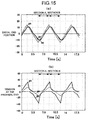
- Fig. 15 illustrates a response result by the conventional art in which a position command signal by operation of the joystick is directly generated as a motor position command signal.
- Fig. 14 (a) and Fig. 15 (a) illustrate time waves in the distal end positions of the upper and lower hauling wires.
- Fig. 14 (b) and Fig. 15 (b) illustrate time waves in which tensions applied to the upper and lower hauling wires of the endoscope inserting portion were measured on the side of the pulley.
- a command signal from the joystick is applied to a command signal 300.
- the pulley 118 illustrated in Fig. 13 is rotated in the direction of arrow (clockwise direction) in a section A, and is rotated in the counterclockwise direction in a section B.
- distal end positions 307 and 308 of the upper and lower wires have phases that delay with respect to a target command signal 300 by about 20 degrees, and gain is in a form of a triangle whose head becomes flat, i.e., in a form of a trapezoid. Therefore, in the conventional art, when an operator desires to allow the distal end of the distal bending section to follow the triangular wave and the operator only inputs a command signal of the triangular wave using the joystick, the phase of the distal end position of the distal bending section delays, and since the gain is in the form of trapezoid, the operator can not precisely position.
- the operator in order to achieve the object, the operator must correct the command signal by himself or herself while visually checking the monitor so that the distal end position of the distal bending section follows the triangular wave. For this reason, skill is required for operation, and since the motorized endoscope is used, a load to the operator is increased.
- the distal end positions 303 and 304 of the upper and lower hauling wires and the target command signal (operation command signal) 300 substantially coincide with each other. Therefore, since the distal end positions of the hauling wires 114 and 116 move in accordance with a command signal, a load to the operator is reduced using the motorized endoscope, and it is possible to position the distal end of the distal bending section to a target location swiftly and precisely.
- a tension 305 at the instant when the rotation direction (operation direction) is changed from the section A to the section B is the greatest, and irrespective of the fact that the rotation direction is changed, the tension is gradually reduced, a tension 306 of the lower wire is zero. That is, irrespective of the fact that a state of slack is shifted to the section B and the rotation direction is changed, the tension starts increasing after about 0.7 seconds due to the slack, and the direction of the distal end position is changed.
- a ninth embodiment of the present invention will be explained with reference to Fig. 16.
- the feedback control system for feedback controlling the distal end position of the hauling wire is removed from the control device illustrated in Fig. 13.
- Other structures of the ninth embodiment are the same as those in Fig. 13.
- a phase of the command signal 146 by an output of the command signal detector 144 is advanced to generate a feedforward control signal, a deviation between the feedforward control signal and the motor position signal 160 is obtained by the adder 156, a drive signal for bringing this deviation to zero is generated by the motor control unit 164, this drive signal is amplified by the motor amplifier 166, and the motor 120 is rotated.
- the distal end position of the distal bending section 112 hauled by the hauling wires 114 and 116 can be allowed to follow the operation command value without delay.
- phase delays due to influences of nonlinearity such as friction between the hauling wires 114 and 116 and the coil sheaths 122 and 124 and the slack of the hauling wires 114 and 116 can be compensated by the feedforward control unit 152. Therefore, if the phase of the operation command signal is advanced by the feedforward control unit 152, it is possible to advance the motion of the pulley 118 with respect to the operation command value.
- Fig. 17B illustrates characteristics of triangular wave 300 indicative of the operation command value and waveform 311 of a motor position command signal that is output from the feedforward control unit 152. It is found from Figs. 17A and 17B that whenever the operation direction is changed by operating the joystick 110, an appropriate offset is added to a command, and the command signal is corrected in a direction in which its phase advances. From this, it is found that as compared with the distal end positions 307 and 308 illustrated in Fig. 15A, the distal end positions 307 and 308 of the hauling wires 114 and 116 in Fig. 17A approach the triangular wave 300 of the command signal.
- a structure in which a symbol is changed may be used as shown in the following equation (2): where R represents a target command signal, and sgn represents its symbol. It is preferable that when speed of the command signal is smaller than a constant value, the magnitude of the gain g is proportional to the speed, and when the speed of the command signal becomes equal to or greater than the constant value, the magnitude of the gain g is equal to the constant value. With this, the speed of the motor 20 can gradually be varied with respect to the change of symbol of the speed and vibration of the wire 114 and 116 can be suppressed.
- the endoscope inserting portion is not provided with special sensors 128, 130 or the feedback control system, costs can be reduced as compared with the eighth embodiment.
- a tenth embodiment of the present invention will be explained with reference to Fig. 18 to Fig. 23.
- tensions of the hauling wires 114 and 116 are detected instead of feeding back the distal end positions of the hauling wires, and the tensions are fed back.
- Tension sensors 168 and 170 for detecting the tensions of the hauling wires 114 and 116 are provided on the side of the pulley 118 of the hauling wires 114 and 116, and detection values of the tension sensors 168 and 170 are input to a wire tension detector 172.
- each tension sensor 168, 170 include a distortion gage 174, a bridge circuit 176 and a differential amplifier circuit 178.
- a fine thin and long distortion gage 174 is mounted to each of the hauling wires 114 and 116. If variation in distortion amount is detected by the distortion gage 174, a signal indicative of the variation of distortion amount is amplified by the differential amplifier circuit 178 through the bridge circuit 176 that varies a resistance in proportion to the variation of the distortion amount. In this case, when no external force is applied to the hauling wires 114 and 116, balance of the bridge circuit 176 is kept by a resistance of the distortion gage 174, and an output of the differential amplifier circuit 178 is zero.
- the tension sensors 168 and 170 and the wire tension detector 172 are constructed as tension detecting units, and the internal tension signal 180 is output to an endoscope state estimator 182 and a position estimator 184.
- Positive and negative of tensions detected by the tension sensors 168 and 170 have the same relation as the characteristics illustrated in Fig. 14B.
- the position estimator 184 is constructed as a position estimating unit.
- the position estimating unit estimates a bend position of the distal bending section 112 from an internal tension signal 180 and an estimated result 186 of the endoscope state estimator 182, and outputs this estimated result 188 to the adder 142 as a hauling property detecting signal.
- the position estimator 184 is constructed by modeling dynamics from the internal tension signal 180 to the distal end positions of the hauling wires 114 and 116. By selecting a designated model from a plurality of models in accordance with the state estimated result 186, the distal end position of the inserting portion can be estimated.
- the model used for the position estimator 184 is constituted by using a plurality of primary low pass filters.
- the model is selected from the state estimated result 186, it is necessary to select a designated model in accordance with a state of the inserting portion of the endoscope. That is, since the inserting portion is inserted into a body cavity or the like, the inserting portion is substantially in a straight state at an initial stage of insertion, but when the inserting portion is inserted along a shape of a bowel or the like, a bending ratio of an intermediate portion of the inserting portion becomes great depending upon a location in some cases.
- the bending ratio is increased, friction between the coil sheaths 122 and 124 and the hauling wires 114 and 116 is increased, characteristics of dynamics from the measured internal tension signal 180 to the distal end positions of the hauling wires 114 and 116 are varied as compared with those when the inserting portion is straight. Further, the characteristics of dynamics are also varied by a using environment state of the endoscope or variation with time. Therefore, in order to further enhancing the estimation precision of the distal end position (bend position) of the hauling wire, it is necessary to estimate these states, to select a model corresponding to this estimation, and to control the feedback control unit 148 in accordance with the selected model.
- the state estimated result 186 for selecting an appropriate model is obtained in accordance with a function that is previously determined from a relation ratio between the command signal 146 indicative of the operation command value and the internal tension signal 180 indicative of magnitude of the internal tension, and the state estimated result 186 is output to the position estimator 184.
- the state estimated result 186 is obtained while taking into account the fact that characteristics variation of dynamics from the internal tension signal 180 to the distal end positions of the hauling wires 114 and 116 appear most remarkably in tension.
- the endoscope state estimator 182 estimates the state of the distal bending section 112 from the operation command value and the internal tension, and the endoscope state estimator 182 is constructed as a state estimating unit that estimates the state of the distal bending section 112 from the operation command value signal 146 and the internal tension signal 180.
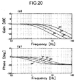
- a model used for the position estimator 184 it is possible to use four primary low pass filters as illustrated in Figs. 20A and 20B. Characteristics of the four models are indicated with 320, 321, 322 and 323, and crossover frequencies of the characteristics are 1 hertz, 2 hertz, 4 hertz, and 8 hertz, respectively.
- characteristics 322 having crossover frequency of 4 hertz is used.
- characteristics 320 having crossover frequency of 1 hertz is used for example.
- the distal end position of a wire using the low pass filter having crossover frequency of 4 hertz was estimated as a model, experiment results as illustrated in Fig. 21 were obtained.
- the endoscope state estimator 182 comprises low pass filters 190 and 192, absolute value calculating circuits 194 and 196, integration circuits 198 and 200, an evaluation value calculating circuit 202, a function reference circuit 204 and a model determining circuit 206.
- a command signal 146 based on the operation of the joystick 110 has been input to the low pass filter 190, and since the command signal 146 passes through the low pass filter 190, noise component is cut off and only signals of necessary band pass.
- a signal that passed through the low pass filter 190 is converted into a positive signal by the absolute value calculating circuit 194, the signal is integrated by constant time T0, and the integrated value is output to the evaluation value calculating circuit 202 as an operation command signal having magnitude of RI.
- the operation command value is defined as R
- RI is obtained by the following equation (3):
- An internal tension signal 180 has been input to a low pass filter 192, noise component of the internal tension signal 180 is removed by the low pass filter 192, and only signals having necessary band pass through the low pass filter 192, and a signal that passed through the low pass filter 192 is converted into a positive signal by the absolute value calculating circuit 196. If the signal is integrated by constant time T0 by an integration circuit 200, the integrated value is output to the evaluation value calculating circuit 202 as a signal indicative of an internal tension C having magnitude of CI. In this case, the magnitude CI of the internal tension C is obtained by the following equation (4):
- an evaluation value concerning a state of the endoscope inserting portion is calculated.
- a relation between an evaluation value and a model crossover frequency as illustrated in Fig. 23 is set. This relation is expressed as shown in the following equation (5): 8 CI/RI
- a model of the model crossover frequency corresponding to the evaluation value is determined by the model determining circuit 206, and this determination is output as a state estimated result 186.
- a model crossover frequency is calculated in accordance with the equation (5), and when the evaluation value is smaller than 1, model crossover frequency is set to 8 hertz. For example, when the evaluation value is 2 and an intersection point with respect to a function is A, the evaluation value is straight, and crossover frequency of 4 hertz is selected as a model at that time.
- the eleventh embodiment comprises a position estimator 208 that estimates distal end positions of the hauling wires 114 and 116 from a motor position signal 160 indicative of a rotation movement amount of the pulley 118 and from an internal tension signal 180, instead of using the endoscope state estimator 182 and the position estimator 184 illustrated in Fig. 18.
- Other structures of the eleventh embodiment are the same as those illustrated in Fig. 18.
- the position estimator 208 is constructed as a position estimating unit.
- the position estimating unit receives a motor position signal 160 detected by the motor position detector 158 and an internal tension signal 180 detected by the wire tension detector 172.
- the position estimating unit estimates distal end positions (bend position of the distal bending section 112) of the hauling wires 114 and 116 based on these signals, and outputs the estimated result 210 to the adder 142 as a hauling property detecting signal.
- the distal end positions of the hauling wires 114 and 116 are estimated from a motor position signal 160 corresponding to the rotation movement amount of the pulley 118 and an internal tension signal 180 indicative of the internal tension, assuming that rigidity of the hauling wires 114 and 116 is already known, the distal end positions of the hauling wires are estimated.
- the internal tension Ten is generated in accordance with the following equation (6):
- Ten K ⁇ (Posp-Posf) where K represents rigidity of the hauling wire 114, 116, Posp represents a moving amount of hauling wire 114, 116 moved because the pulley 118 rotates, and Posf represents a distal end position of the hauling wire.
- the equation (6) can be deformed into the following equation (7):
- Posf Posp - Ten/K
- the moving amount of wire of the Posp can be obtained by multiplying a gear ratio by a radius of the pulley 118 from a detection value of the rotary encoder 162. With this, the distal end positions of the hauling wires can be estimated in real time.
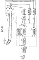
- a twelfth embodiment of the present invention will be explained with reference to Fig. 25.
- a command signal 146 is converted into a tension command signal 214 in a command signal converter 212, a deviation between the tension command signal 214 and the internal tension signal 180 is obtained by the adder 142, and this deviation is fed back controlled by the feedback control unit 148.
- Other structures of the twelfth embodiment are the same as those illustrated in Fig. 16.
- the command signal converter 212 is constructed as a command signal converting unit that includes a primary high pass filter for example.
- the command signal converting unit converts the command signal 146 into the tension command signal 214.
- a tension command can be input directly to an input unit such as the joystick 110
- a deviation between the signal and the internal tension may be input to the feedback control unit 148.
- the hauling wires 114 and 116 illustrated in Fig. 13 are wound around a relay pulley 218 provided in an operation section 216, one ends of hauling wires 220 and 222 are wound around the relay pulley 218 and inserted into coil sheaths 224 and 226, and the other ends of the hauling wires 220 and 222 are wound around the pulley 218, and the hauling wires 114 and 116 and the hauling wires 220 and 222 are connected to each other through the relay pulley 218, thereby constituting a plurality of hauling units.
- the relay pulley 218 is provided with a potentiometer 228 for detecting a rotation angle of the relay pulley 218.
- a rotation angle signal 230 detected by the potentiometer 228 is output to the relay position detector 232. That is, in the thirteenth embodiment, by providing the operation section 216 at an intermediate portion of the inserting portion through the relay pulley 218, a length of the inserting portion is shortened.
- the hauling wires 220 and 222 and the coil sheaths 224 and 226 located from the motor 120 to the relay pulley 218 are disposed in a universal cord in which an electrographic system such as CCD mounted to the distal end distal bending section 126. An operator can operate, using his or her thumb or the like, an input unit (not illustrated) such as the joystick 110 mounted to the operation section 216 that covers the relay pulley 218.
- the relay position detector 232 outputs a relay position signal 234 indicative of a rotation angle of the relay pulley 218 to the adder 236 based on a rotation angle signal 230. That is, the potentiometer 228 and the relay position detector 232 are constructed as relay position detecting units that detect a position where a relay hauling unit of the hauling units drives, and output a relay position signal 234.
- the adder 236 receives a motor position command value signal 154 output from the adder 150 as a relay pulley position command signal, obtains a deviation between the relay pulley position command signal and the relay position signal 234, and outputs the deviation to the relay position feedback control unit 238.
- the relay position feedback control unit 238 generates a relay position feedback control signal for suppressing the deviation calculated by the adder 236 to zero, and outputs the relay position feedback control signal to the adder 156 as a motor position command signal.
- the adder 156 obtains a deviation between the motor position command signal and the motor position signal 160, and a drive signal corresponding to the deviation is generated by the motor control unit 164, and the drive signal is amplified by the motor amplifier 166 to drive the motor 120. That is, in the motor control unit 164, reaction of a tension applied to the pulley 118 is canceled, and the rotation angle of the motor 120 is allowed to follow the motor position command signal.
- the phase of the operation command value is advanced, and dynamics from a position of the pulley where the phase delays to the distal end position of the wire are moved.
- the operation section 216 is increased in size and weight. Therefore, when the rotation angle of the relay pulley 218 can not be detected, the feedback of the motor position and the feedback of the wire position may be carried out.
- the motor position command signal may be generated only by the feedforward control unit 152 comprising a phase leading filter.
- a tension sensor may be mounted to the inserting portion, and a distal end position of the wire may be estimated from a tension detected by the tension sensor.
- a tension sensor may be mounted to the hauling wire closer to the motor, and a position of the hauling wire may be estimated and the feedback may be carried out.
- the thirteenth embodiment basically comprises a combination of two endoscope inserting portions, a plurality of hauling units may be provided also in the eighth embodiment to the twelfth embodiment. Further, one more relay pulley 218 may be added.
- distal bending section 112 of the motorized endoscope is operated in each of the embodiments
- another apparatus that operates a distal end by hauling the distal end using a hauling wire or the like, e.g., an apparatus opens and closes an opening using a wire such as a wire-driving robot arm (arm) or forceps may be operated.
- a wire-driving robot arm (arm) or forceps may be operated.
- feedforward control unit and feedforward control unit are used in the embodiment, even if one of them is provided, the same effect can be achieved.
- control device comprises an analogue circuit, but the control device can also be controlled digitally using a microcomputer or the like.
- the bend position that is to be operated can follow the operation command signal instantaneously, and this can enhance the operability.
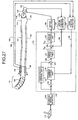
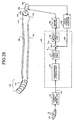
- Fig. 27 illustrates a structure of the motorized endoscope in which the structure illustrated in Fig. 1 is applied to the structure illustrated in Fig. 13.
- the control device 11 illustrated in Fig. 1 from which the motor control unit 13 is removed is provided in front of the motor control unit 164 illustrated in Fig. 27.
- the motorized endoscope of the fourteenth embodiment exhibits the effect of the motorized endoscope of the eighth embodiment illustrated in Fig. 13, and exhibits the effect of the motorized endoscope of the first embodiment illustrated in Fig. 1.
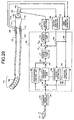
- control device 11 of the first embodiment illustrated in Fig. 1 is applied to the motorized endoscope of the ninth embodiment illustrated in Fig. 16.
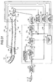
- control device 11 of the first embodiment illustrated in Fig. 1 is applied to the motorized endoscope of the tenth embodiment illustrated in Fig. 18.
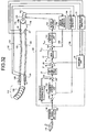
- a motorized endoscope illustrated in Fig. 30 the control device 11 of the second embodiment illustrated in Fig. 6 is applied to the motorized endoscope of the ninth embodiment illustrated in Fig. 16.
- the control device 11 of the third embodiment illustrated in Fig. 7 is applied to the motorized endoscope of the ninth embodiment illustrated in Fig. 16.
- the control device 11 of the fifth embodiment illustrated in Fig. 10 is applied to the motorized endoscope of the ninth embodiment illustrated in Fig. 16.
- the bend position to be operated can instantaneously follow the operation command value, and the operability can be enhanced, and even if slack is generated in both retrieving units at the neutral reference position, the slack can be controlled at the neutral reference position, and it is possible to swiftly and precisely position the towed mechanism.
- the apparatus for traction positional control according to the present invention, even if a slack is generated in both the hauling units at the neutral reference position, is capable of controlling the slack at the neutral reference position, and swiftly and precisely positioning the towed mechanism, and at the same time, is capable of compensating an offset of the position to make a bending position of an object under controlling instantly keep up with an operation instruction, and thereby contributing to an enhancement of operationality. Therefore, it is suitable for bending or rotating an object of a motorized traction mechanism such as a motorized endoscope or a robot arm by hauling a traction member such as a wire.
- a motorized traction mechanism such as a motorized endoscope or a robot arm by hauling a traction member such as a wire.
Landscapes
- Health & Medical Sciences (AREA)
- Life Sciences & Earth Sciences (AREA)
- Surgery (AREA)
- Biomedical Technology (AREA)
- Medical Informatics (AREA)
- Optics & Photonics (AREA)
- Pathology (AREA)
- Radiology & Medical Imaging (AREA)
- Biophysics (AREA)
- Engineering & Computer Science (AREA)
- Physics & Mathematics (AREA)
- Heart & Thoracic Surgery (AREA)
- Nuclear Medicine, Radiotherapy & Molecular Imaging (AREA)
- Molecular Biology (AREA)
- Animal Behavior & Ethology (AREA)
- General Health & Medical Sciences (AREA)
- Public Health (AREA)
- Veterinary Medicine (AREA)
- Endoscopes (AREA)
- Manipulator (AREA)
- Instruments For Viewing The Inside Of Hollow Bodies (AREA)
Abstract
Description



Claims (19)
- An apparatus for traction positional control comprising:a hauling unit that hauls a subject to bend or rotate the subject;a driving unit that drives the hauling unit; anda control unit that outputs a control signal to the driving unit, corresponding to a target value that is input by an operating unit, whereinthe control unit controls a variation amount of the control signal output in a predetermined range including a position of the hauling unit in a state before the hauling unit hauls the subject to be greater than a variation amount of the control signal output outside the predetermined range.
- The apparatus according to claim 1, wherein the control unit outputs the control signal based on the target value, wherein the target value is either of an amount of bending and an amount of rotating of the subject.
- The apparatus according to claim 1, wherein the control unit outputs the control signal based on the target value, wherein the target value is either of a speed of bending and a speed of rotating of the subject.
- The apparatus according to claim 1, wherein the control unit determines the control signal by compensating the target value based on a predetermined parameter.
- The apparatus according to claim 1, wherein
the control unit determines the control signal by compensating the target value based on a parameter, and
the control unit renews the parameter based on a state parameter of the hauling unit. - The apparatus according to claim 5, wherein the state parameter is a tension of the hauling unit.
- The apparatus according to claim 1, wherein
the control unit determines the control signal by multiplying the target value by a variable gain, and
the control unit renews the variable gain based on a state parameter of the hauling unit. - The apparatus according to claim 7, wherein the state parameter is a tension of the hauling unit.
- An apparatus for traction positional control comprising:a wire that hauls a subject to bend or rotate the subject;a motor that drives the wire; anda control unit that outputs a control signal to the motor, corresponding to a target value that is input by a joystick, whereinthe control unit controls a variation amount of the control signal output in a predetermined range including a position of the wire in a state before the wire hauls the subject to be greater than a variation amount of the control signal output outside the predetermined range.
- An apparatus for traction positional control comprising:a hauling unit that hauls a subject to bend or rotate the subject;a driving unit that drives the hauling unit;an output unit that outputs an operation command value signal corresponding to a target value that is input by an operating unit;a feedforward control unit that compensates the operation command value signal based on a feedforward compensation value, and generates a feedforward control signal;a drive control unit that generates a control signal based on the feedforward control signal; anda compensating unit that is arranged in a previous stage of the drive control unit, and controls a variation amount of the control signal output in a predetermined range including a position of the hauling unit in a state before the hauling unit hauls the subject to be greater than a variation amount of the control signal output outside the predetermined range.
- The apparatus according to claim 10, further comprising:a hauling state detecting unit that detects a hauling state of the hauling unit, and outputs a hauling state detecting signal;a second deviation calculating unit that calculates a second deviation between the operation command value signal and the hauling state detecting signal;a feedback control unit that generates a feedback control signal to suppress the second deviation to zero; anda signal generation unit that generates a compensation signal that is obtained by compensating the feedforward control signal using the feedback control signal, and outputs the compensation signal to the drive control unit.
- The apparatus according to claim 11, wherein the hauling state detecting unit comprises
a tension detecting unit that detects a tension of the hauling unit;
a state estimating unit that estimates a state of the subject based on the operation command value signal and the tension; and
a dynamics changing unit that changes dynamics of the feedforward control unit and dynamics of the feedback control unit based on a result of the state estimating unit. - The apparatus according to claim 10, wherein the correction control unit outputs the control signal based on the target value, wherein the target value is either of an amount of bending and an amount of rotating of the subject.
- The apparatus according to claim 10, wherein the correction control unit outputs the control signal based on the target value, wherein the target value is either of a speed of bending and a speed of rotating of the subject.
- The apparatus according to claim 10, wherein the correction control unit determines the control signal by compensating the target value based on a predetermined parameter.
- The apparatus according to claim 10, wherein
the correction control unit determines the control signal by compensating the target value based on a parameter, and
the correction control unit renews the parameter based on a state parameter of the hauling unit. - The apparatus according to claim 10, wherein the state parameter is a tension of the hauling unit.
- The apparatus according to claim 10, wherein
the correction control unit determines the control signal by multiplying the target value by a variable gain, and
the correction control unit renews the variable gain based on a state parameter of the hauling unit. - The apparatus according to claim 18, wherein the state parameter is a tension of the hauling unit.
Applications Claiming Priority (3)
| Application Number | Priority Date | Filing Date | Title |
|---|---|---|---|
| JP2002205265 | 2002-07-15 | ||
| JP2002205265A JP3973504B2 (en) | 2002-07-15 | 2002-07-15 | Tow positioning device |
| PCT/JP2003/008992 WO2004006757A1 (en) | 2002-07-15 | 2003-07-15 | Towing positioning device |
Publications (3)
| Publication Number | Publication Date |
|---|---|
| EP1464270A1 true EP1464270A1 (en) | 2004-10-06 |
| EP1464270A4 EP1464270A4 (en) | 2006-06-07 |
| EP1464270B1 EP1464270B1 (en) | 2008-10-29 |
Family
ID=30112755
Family Applications (1)
| Application Number | Title | Priority Date | Filing Date |
|---|---|---|---|
| EP03741413A Expired - Lifetime EP1464270B1 (en) | 2002-07-15 | 2003-07-15 | Towing positioning device |
Country Status (5)
| Country | Link |
|---|---|
| US (1) | US7348751B2 (en) |
| EP (1) | EP1464270B1 (en) |
| JP (1) | JP3973504B2 (en) |
| DE (1) | DE60324383D1 (en) |
| WO (1) | WO2004006757A1 (en) |
Cited By (5)
| Publication number | Priority date | Publication date | Assignee | Title |
|---|---|---|---|---|
| US8403833B2 (en) | 2009-11-18 | 2013-03-26 | Olympus Medical Systems Corp. | Medical apparatus |
| US8864752B2 (en) | 2006-06-13 | 2014-10-21 | Intuitive Surgical Operations, Inc. | Control system configured to compensate for non-ideal actuator-to-joint linkage characteristics in a medical robotic system |
| JP2015147059A (en) * | 2006-06-13 | 2015-08-20 | インテュイティブ サージカル インコーポレイテッド | Surgical instrument assembly |
| US9161682B2 (en) | 2010-03-02 | 2015-10-20 | Olympus Corporation | Medical system and control method |
| EP3795057A4 (en) * | 2018-05-15 | 2021-06-23 | Shenzhen Yateks Optical Electronic Technology Co., Ltd. | ENDOSCOPE AND ENDOSCOPE DIRECTION ADJUSTMENT PROCESS |
Families Citing this family (49)
| Publication number | Priority date | Publication date | Assignee | Title |
|---|---|---|---|---|
| US7576509B2 (en) * | 2003-09-10 | 2009-08-18 | Ricoh Company, Limited | Drive control method, drive control device, belt apparatus, image forming apparatus, image reading apparatus, computer product |
| US20060069310A1 (en) * | 2004-09-30 | 2006-03-30 | Couvillon Lucien A Jr | Programmable brake control system for use in a medical device |
| JP4599177B2 (en) * | 2005-01-13 | 2010-12-15 | オリンパス株式会社 | Electric bending endoscope |
| JP2006314775A (en) * | 2005-04-12 | 2006-11-24 | Olympus Corp | Endoscope system |
| EP3788944B1 (en) * | 2005-11-22 | 2024-02-28 | Intuitive Surgical Operations, Inc. | System for determining the shape of a bendable instrument |
| EP1958294A4 (en) * | 2005-11-23 | 2011-09-21 | Neoguide Systems Inc | Non-metallic, multi-strand control cable for steerable instruments |
| EP2124709B1 (en) * | 2007-02-23 | 2016-08-31 | Université de Strasbourg (Etablissement Public à Caractère Scientifique, Culturel et Professionnel) | Flexible endoscope device with visual control |
| JP5295555B2 (en) * | 2007-12-10 | 2013-09-18 | オリンパスメディカルシステムズ株式会社 | Endoscope system |
| EP2098159A1 (en) * | 2008-03-04 | 2009-09-09 | FUJIFILM Corporation | Endoscope |
| US9161817B2 (en) | 2008-03-27 | 2015-10-20 | St. Jude Medical, Atrial Fibrillation Division, Inc. | Robotic catheter system |
| US8317744B2 (en) | 2008-03-27 | 2012-11-27 | St. Jude Medical, Atrial Fibrillation Division, Inc. | Robotic catheter manipulator assembly |
| US9241768B2 (en) | 2008-03-27 | 2016-01-26 | St. Jude Medical, Atrial Fibrillation Division, Inc. | Intelligent input device controller for a robotic catheter system |
| WO2009120992A2 (en) | 2008-03-27 | 2009-10-01 | St. Jude Medical, Arrial Fibrillation Division Inc. | Robotic castheter system input device |
| US8684962B2 (en) | 2008-03-27 | 2014-04-01 | St. Jude Medical, Atrial Fibrillation Division, Inc. | Robotic catheter device cartridge |
| WO2009120982A2 (en) | 2008-03-27 | 2009-10-01 | St. Jude Medical, Atrial Fibrillation Division, Inc. | Robotic catheter system with dynamic response |
| US20090248042A1 (en) * | 2008-03-27 | 2009-10-01 | Kirschenman Mark B | Model catheter input device |
| US8343096B2 (en) | 2008-03-27 | 2013-01-01 | St. Jude Medical, Atrial Fibrillation Division, Inc. | Robotic catheter system |
| FR2945232B1 (en) * | 2009-05-06 | 2011-04-22 | Commissariat Energie Atomique | FRICTION COMPENSATION METHOD IN AN EFFORT RETURN DEVICE EQUIPPED WITH A CABLE TRANSMISSION |
| JP4782894B2 (en) * | 2009-06-11 | 2011-09-28 | オリンパスメディカルシステムズ株式会社 | Medical control device |
| US9439736B2 (en) | 2009-07-22 | 2016-09-13 | St. Jude Medical, Atrial Fibrillation Division, Inc. | System and method for controlling a remote medical device guidance system in three-dimensions using gestures |
| US9330497B2 (en) | 2011-08-12 | 2016-05-03 | St. Jude Medical, Atrial Fibrillation Division, Inc. | User interface devices for electrophysiology lab diagnostic and therapeutic equipment |
| DE102009054367A1 (en) * | 2009-11-19 | 2011-05-26 | Karl Storz Gmbh & Co. Kg | Endoscope with flexible endoscope shaft |
| US9888973B2 (en) | 2010-03-31 | 2018-02-13 | St. Jude Medical, Atrial Fibrillation Division, Inc. | Intuitive user interface control for remote catheter navigation and 3D mapping and visualization systems |
| JP5355489B2 (en) * | 2010-04-30 | 2013-11-27 | オリンパス株式会社 | Optical potentiometer |
| DE112011104865B4 (en) * | 2011-02-09 | 2019-01-17 | Mitsubishi Electric Corporation | Sensor control device |
| WO2012153646A1 (en) | 2011-05-12 | 2012-11-15 | オリンパスメディカルシステムズ株式会社 | Medical control device |
| JP2013022184A (en) * | 2011-07-20 | 2013-02-04 | Olympus Medical Systems Corp | Endoscope |
| JP6012950B2 (en) * | 2011-10-14 | 2016-10-25 | オリンパス株式会社 | Bending motion system |
| JP6037964B2 (en) | 2013-07-26 | 2016-12-07 | オリンパス株式会社 | Manipulator system |
| JP6116427B2 (en) * | 2013-07-26 | 2017-04-19 | オリンパス株式会社 | Manipulator and manipulator system |
| JP6027947B2 (en) * | 2013-07-26 | 2016-11-16 | オリンパス株式会社 | Manipulator system |
| JP6270537B2 (en) * | 2014-02-27 | 2018-01-31 | オリンパス株式会社 | Medical system |
| JP6278747B2 (en) * | 2014-02-28 | 2018-02-14 | オリンパス株式会社 | Manipulator calibration method, manipulator, and manipulator system |
| JP6374672B2 (en) | 2014-02-28 | 2018-08-15 | オリンパス株式会社 | Medical instruments and medical systems |
| US10874474B2 (en) | 2015-05-15 | 2020-12-29 | Intuitive Surgical Operations, Inc. | System and method for force or torque limit compensation |
| US10448805B2 (en) | 2015-09-28 | 2019-10-22 | Bio-Medical Engineering (HK) Limited | Endoscopic systems, devices and methods |
| JP6921602B2 (en) | 2017-04-21 | 2021-08-18 | キヤノン株式会社 | Continuum robot control system, its control method, and program |
| JP6949959B2 (en) * | 2017-07-06 | 2021-10-13 | オリンパス株式会社 | Tubular insertion device and operation support method using the tubular insertion device |
| GB201718271D0 (en) * | 2017-11-03 | 2017-12-20 | Surgical Dynamics Ltd | Obstetric Forceps |
| US11071441B2 (en) * | 2018-04-20 | 2021-07-27 | Verb Surgical Inc. | Surgical robotic tool multi-motor actuator and controller |
| CN110711750B (en) * | 2019-10-30 | 2023-10-13 | 汕头市澄海区骏意玩具设计有限公司 | Pipeline cleaning robot, control method and storage medium |
| US11586275B2 (en) * | 2020-01-09 | 2023-02-21 | Baker Hughes Oilfield Operations Llc | Cable force adjustment |
| WO2021145051A1 (en) | 2020-01-16 | 2021-07-22 | オリンパス株式会社 | Endoscope system |
| CN113349715A (en) * | 2020-03-02 | 2021-09-07 | 南微医学科技股份有限公司 | Steering fixing head, catheter steering traction mechanism, steering device and endoscope |
| CN112083329A (en) * | 2020-08-19 | 2020-12-15 | 中车长春轨道客车股份有限公司 | Debugging system and debugging method for judging rotating direction of traction motor of motor train unit |
| EP4212105A1 (en) * | 2021-10-18 | 2023-07-19 | ROEN Surgical, Inc. | Hysteresis compensation control apparatus of flexible tube |
| CN118159178A (en) * | 2021-11-22 | 2024-06-07 | 奥林巴斯医疗株式会社 | Medical manipulator system, medical manipulator control method and control device |
| WO2023090021A1 (en) | 2021-11-22 | 2023-05-25 | オリンパスメディカルシステムズ株式会社 | Endoluminal device system, endoluminal device control method, and computer program recording medium for storing program that controls endoluminal device |
| US20240298884A1 (en) * | 2023-03-06 | 2024-09-12 | Olympus Medical Systems Corp. | Medical manipulator system and control method and processor for medical manipulator system |
Family Cites Families (10)
| Publication number | Priority date | Publication date | Assignee | Title |
|---|---|---|---|---|
| JPS5586436A (en) * | 1978-12-22 | 1980-06-30 | Olympus Optical Co | Endoscope |
| JPS6359329A (en) | 1986-08-28 | 1988-03-15 | Kurita Water Ind Ltd | water scrubber |
| US4941454A (en) | 1989-10-05 | 1990-07-17 | Welch Allyn, Inc. | Servo actuated steering mechanism for borescope or endoscope |
| JP3230607B2 (en) * | 1992-07-09 | 2001-11-19 | オリンパス光学工業株式会社 | Electric endoscope device |
| JP3397940B2 (en) | 1995-06-30 | 2003-04-21 | オリンパス光学工業株式会社 | Electric bending endoscope device |
| AU712738B2 (en) * | 1997-09-24 | 1999-11-18 | Eclipse Surgical Technologies, Inc. | Steerable catheter |
| JP4436479B2 (en) | 1999-04-23 | 2010-03-24 | オリンパス株式会社 | Endoscope and angle wire driving method |
| JP2001275941A (en) * | 2000-03-31 | 2001-10-09 | Olympus Optical Co Ltd | Electric bending endoscope device |
| US6478743B2 (en) * | 2001-03-16 | 2002-11-12 | Ge Medical Systems Global Technology Company, Llc | Transesophageal ultrasound probe with imaging element position sensor in scanhead |
| US6669629B2 (en) * | 2001-04-24 | 2003-12-30 | Olympus Optical Co., Ltd. | Endoscope system comprising an electrically bendable endoscope |
-
2002
- 2002-07-15 JP JP2002205265A patent/JP3973504B2/en not_active Expired - Fee Related
-
2003
- 2003-07-15 DE DE60324383T patent/DE60324383D1/en not_active Expired - Lifetime
- 2003-07-15 US US10/620,236 patent/US7348751B2/en not_active Expired - Fee Related
- 2003-07-15 WO PCT/JP2003/008992 patent/WO2004006757A1/en not_active Ceased
- 2003-07-15 EP EP03741413A patent/EP1464270B1/en not_active Expired - Lifetime
Cited By (7)
| Publication number | Priority date | Publication date | Assignee | Title |
|---|---|---|---|---|
| US8864752B2 (en) | 2006-06-13 | 2014-10-21 | Intuitive Surgical Operations, Inc. | Control system configured to compensate for non-ideal actuator-to-joint linkage characteristics in a medical robotic system |
| JP2015147059A (en) * | 2006-06-13 | 2015-08-20 | インテュイティブ サージカル インコーポレイテッド | Surgical instrument assembly |
| US9283049B2 (en) | 2006-06-13 | 2016-03-15 | Intuitive Surgical Operations, Inc. | Control system configured to compensate for non-ideal actuator-to-joint linkage characteristics in a medical robotic system |
| EP2038712B2 (en) † | 2006-06-13 | 2019-08-28 | Intuitive Surgical Operations, Inc. | Control system configured to compensate for non-ideal actuator-to-joint linkage characteristics in a medical robotic system |
| US8403833B2 (en) | 2009-11-18 | 2013-03-26 | Olympus Medical Systems Corp. | Medical apparatus |
| US9161682B2 (en) | 2010-03-02 | 2015-10-20 | Olympus Corporation | Medical system and control method |
| EP3795057A4 (en) * | 2018-05-15 | 2021-06-23 | Shenzhen Yateks Optical Electronic Technology Co., Ltd. | ENDOSCOPE AND ENDOSCOPE DIRECTION ADJUSTMENT PROCESS |
Also Published As
| Publication number | Publication date |
|---|---|
| WO2004006757A1 (en) | 2004-01-22 |
| JP3973504B2 (en) | 2007-09-12 |
| JP2004041538A (en) | 2004-02-12 |
| US20040138530A1 (en) | 2004-07-15 |
| US7348751B2 (en) | 2008-03-25 |
| DE60324383D1 (en) | 2008-12-11 |
| EP1464270A4 (en) | 2006-06-07 |
| EP1464270B1 (en) | 2008-10-29 |
Similar Documents
| Publication | Publication Date | Title |
|---|---|---|
| EP1464270B1 (en) | Towing positioning device | |
| JP2002264048A (en) | Positioning control device for towed mechanism | |
| JP4757838B2 (en) | Positioning control device for towed mechanism | |
| JP6037964B2 (en) | Manipulator system | |
| US20080221592A1 (en) | Medical control apparatus | |
| EP2151184B1 (en) | Active drive type medical apparatus | |
| KR101806385B1 (en) | Drive force control in medical instrument providing position measurements | |
| US10085624B2 (en) | Manipulator and manipulator system | |
| JP5559996B2 (en) | Endoscope device, endoscope system, and operation method of endoscope device | |
| CN102368944A (en) | Medical control device | |
| US10085612B2 (en) | Manipulator and manipulator system | |
| US20160361819A1 (en) | Manipulator-calibrating method, manipulator, and manipulator system | |
| WO2010090059A1 (en) | Manipulator | |
| WO2011161765A1 (en) | Robot control device | |
| EP2470105A2 (en) | System and method for endovascular telerobotic access | |
| CN101642363A (en) | Active medical apparatus system | |
| JP4436479B2 (en) | Endoscope and angle wire driving method | |
| JP5963981B2 (en) | Insertion device | |
| JP2008196283A (en) | Door opening/closing assist device | |
| JP2009119063A (en) | Traction equipment | |
| US9298194B2 (en) | Method to control medical equipment | |
| US20210186306A1 (en) | Manipulator system, and control method of manipulator system | |
| JP3230607B2 (en) | Electric endoscope device | |
| KR102616257B1 (en) | Hysteresis compensation apparatus of flexible tube and method thereof | |
| KR20150041346A (en) | Method and system for controlling articulated manipulator |
Legal Events
| Date | Code | Title | Description |
|---|---|---|---|
| PUAI | Public reference made under article 153(3) epc to a published international application that has entered the european phase |
Free format text: ORIGINAL CODE: 0009012 |
|
| 17P | Request for examination filed |
Effective date: 20040422 |
|
| AK | Designated contracting states |
Kind code of ref document: A1 Designated state(s): AT BE BG CH CY CZ DE DK EE ES FI FR GB GR HU IE IT LI LU MC NL PT RO SE SI SK TR |
|
| RAP1 | Party data changed (applicant data changed or rights of an application transferred) |
Owner name: OLYMPUS CORPORATION |
|
| RBV | Designated contracting states (corrected) |
Designated state(s): DE FR GB |
|
| A4 | Supplementary search report drawn up and despatched |
Effective date: 20060428 |
|
| 17Q | First examination report despatched |
Effective date: 20061019 |
|
| 17Q | First examination report despatched |
Effective date: 20061019 |
|
| GRAP | Despatch of communication of intention to grant a patent |
Free format text: ORIGINAL CODE: EPIDOSNIGR1 |
|
| GRAS | Grant fee paid |
Free format text: ORIGINAL CODE: EPIDOSNIGR3 |
|
| GRAA | (expected) grant |
Free format text: ORIGINAL CODE: 0009210 |
|
| AK | Designated contracting states |
Kind code of ref document: B1 Designated state(s): DE FR GB |
|
| REG | Reference to a national code |
Ref country code: GB Ref legal event code: FG4D |
|
| REF | Corresponds to: |
Ref document number: 60324383 Country of ref document: DE Date of ref document: 20081211 Kind code of ref document: P |
|
| PLBE | No opposition filed within time limit |
Free format text: ORIGINAL CODE: 0009261 |
|
| STAA | Information on the status of an ep patent application or granted ep patent |
Free format text: STATUS: NO OPPOSITION FILED WITHIN TIME LIMIT |
|
| 26N | No opposition filed |
Effective date: 20090730 |
|
| REG | Reference to a national code |
Ref country code: FR Ref legal event code: PLFP Year of fee payment: 14 |
|
| REG | Reference to a national code |
Ref country code: FR Ref legal event code: CA Effective date: 20161108 |
|
| REG | Reference to a national code |
Ref country code: FR Ref legal event code: PLFP Year of fee payment: 15 |
|
| REG | Reference to a national code |
Ref country code: FR Ref legal event code: PLFP Year of fee payment: 16 |
|
| PGFP | Annual fee paid to national office [announced via postgrant information from national office to epo] |
Ref country code: DE Payment date: 20190719 Year of fee payment: 17 Ref country code: FR Payment date: 20190719 Year of fee payment: 17 |
|
| PGFP | Annual fee paid to national office [announced via postgrant information from national office to epo] |
Ref country code: GB Payment date: 20190719 Year of fee payment: 17 |
|
| REG | Reference to a national code |
Ref country code: DE Ref legal event code: R119 Ref document number: 60324383 Country of ref document: DE |
|
| GBPC | Gb: european patent ceased through non-payment of renewal fee |
Effective date: 20200715 |
|
| PG25 | Lapsed in a contracting state [announced via postgrant information from national office to epo] |
Ref country code: FR Free format text: LAPSE BECAUSE OF NON-PAYMENT OF DUE FEES Effective date: 20200731 Ref country code: GB Free format text: LAPSE BECAUSE OF NON-PAYMENT OF DUE FEES Effective date: 20200715 |
|
| PG25 | Lapsed in a contracting state [announced via postgrant information from national office to epo] |
Ref country code: DE Free format text: LAPSE BECAUSE OF NON-PAYMENT OF DUE FEES Effective date: 20210202 |