EP1462893A2 - Uniaxial drive unit - Google Patents
Uniaxial drive unit Download PDFInfo
- Publication number
- EP1462893A2 EP1462893A2 EP04007114A EP04007114A EP1462893A2 EP 1462893 A2 EP1462893 A2 EP 1462893A2 EP 04007114 A EP04007114 A EP 04007114A EP 04007114 A EP04007114 A EP 04007114A EP 1462893 A2 EP1462893 A2 EP 1462893A2
- Authority
- EP
- European Patent Office
- Prior art keywords
- pulse
- generating device
- fixed
- moving
- tiltable
- Prior art date
- Legal status (The legal status is an assumption and is not a legal conclusion. Google has not performed a legal analysis and makes no representation as to the accuracy of the status listed.)
- Withdrawn
Links
Images


Classifications
-
- G—PHYSICS
- G05—CONTROLLING; REGULATING
- G05B—CONTROL OR REGULATING SYSTEMS IN GENERAL; FUNCTIONAL ELEMENTS OF SUCH SYSTEMS; MONITORING OR TESTING ARRANGEMENTS FOR SUCH SYSTEMS OR ELEMENTS
- G05B19/00—Program-control systems
- G05B19/02—Program-control systems electric
- G05B19/18—Numerical control [NC], i.e. automatically operating machines, in particular machine tools, e.g. in a manufacturing environment, so as to execute positioning, movement or co-ordinated operations by means of program data in numerical form
- G05B19/409—Numerical control [NC], i.e. automatically operating machines, in particular machine tools, e.g. in a manufacturing environment, so as to execute positioning, movement or co-ordinated operations by means of program data in numerical form characterised by using manual data input [MDI] or by using control panel, e.g. controlling functions with the panel; characterised by control panel details or by setting parameters
-
- G—PHYSICS
- G05—CONTROLLING; REGULATING
- G05B—CONTROL OR REGULATING SYSTEMS IN GENERAL; FUNCTIONAL ELEMENTS OF SUCH SYSTEMS; MONITORING OR TESTING ARRANGEMENTS FOR SUCH SYSTEMS OR ELEMENTS
- G05B2219/00—Program-control systems
- G05B2219/30—Nc systems
- G05B2219/35—Nc in input of data, input till input file format
- G05B2219/35457—Joystick for coarse, rotary encoder for fine movement
-
- G—PHYSICS
- G05—CONTROLLING; REGULATING
- G05B—CONTROL OR REGULATING SYSTEMS IN GENERAL; FUNCTIONAL ELEMENTS OF SUCH SYSTEMS; MONITORING OR TESTING ARRANGEMENTS FOR SUCH SYSTEMS OR ELEMENTS
- G05B2219/00—Program-control systems
- G05B2219/30—Nc systems
- G05B2219/41—Servomotor, servo controller till figures
- G05B2219/41105—Coarse fine
-
- G—PHYSICS
- G05—CONTROLLING; REGULATING
- G05B—CONTROL OR REGULATING SYSTEMS IN GENERAL; FUNCTIONAL ELEMENTS OF SUCH SYSTEMS; MONITORING OR TESTING ARRANGEMENTS FOR SUCH SYSTEMS OR ELEMENTS
- G05B2219/00—Program-control systems
- G05B2219/30—Nc systems
- G05B2219/41—Servomotor, servo controller till figures
- G05B2219/41337—Linear drive motor, voice coil
Definitions
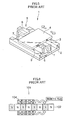
- Fig. 5 is a perspective view showing one example of the uniaxial drive unit.
- a uniaxial drive unit 1 has a fixed table 2, a moving table 4 which is supported on sliding faces 3, 3 so as to be slidable in the uniaxial direction (the arrow-marked directions in Fig. 5) with respect to the fixed table 2, and a motor driving mechanism 5.
- a screw member 6 of the motor driving mechanism 5 is fixed to the fixed table 2 via bearings 7, 7 so as to be rotatable, and a nut member, not shown, engaging with the screw member 6 is fixed to the moving table 4.
- FIG. 6 schematically shows a cross section of such a linear motor 101.
- a moving part 104 which is a ring-shaped member having a coil member, is fitted on a fixed part 102, which is a rod-shaped magnet in which the N poles and the S poles are arranged alternately in a linear form. Due to the interaction between the magnetic flux of the fixed part 102 and the electric current flowing in the coil member of the moving part 104, the moving part 104 moves linearly along the fixed part 102 in accordance with Fleming's left-hand rule.
- the coil member of the moving part 104 is supplied with an electric current by a driving circuit, not shown.
- the uniaxial drive unit in which in the case of a screw feed mechanism as shown in Fig. 5, a manual knob for fine feed is connected to the screw member via a deceleration mechanism, and fine feed is provided to the moving table by manually turning the manual knob.
- the manual knob turns at the time of electrical feed, which entails a danger.
- the present invention has been made in view of the above situation, and accordingly an object thereof is to provide a uniaxial drive unit using a pulse drive motor, with which the operator can perform a fine feed operation easily.
- the present invention provides a uniaxial drive unit comprising a pulse drive motor having a fixed part and a moving part, which is driven by an applied pulse voltage; a fixed table; and a moving table which is supported so as to be slidable in the uniaxial direction with respect to the fixed table, wherein one of the fixed part and moving part is fixed to the fixed table, and the other of the fixed part and moving part is fixed to the moving table, a rotary pulse generating device having a knob, which is a device for generating an electric pulse for driving the pulse drive motor, is provided, the rotary pulse generating device generating a pulse of a frequency corresponding to the turning speed of the knob and generating pulses of the number corresponding to the turning angle of the knob, and fine feed is provided to the moving table by the pulse generated by the rotary pulse generating device.
- the uniaxial drive unit is provided with the rotary pulse generating device for driving the pulse drive motor by generating a pulse of a frequency corresponding to the turning speed of the knob and generating pulses of the number corresponding to the turning angle of the knob. Therefore, merely by turning the knob manually, fine feed can be provided to the moving table safely and easily.
- the moving table can be driven properly with less cogging and less unevenness of speed.
- the present invention provides the uniaxial drive unit characterized in that a tiltable pulse generating device having a tiltable lever, which is a device for generating an electric pulse for driving the pulse drive motor, is provided, the tiltable pulse generating device generating a continuous pulse of a frequency corresponding to the tilt angle of the tiltable lever, and the moving table is moved continuously by the continuous pulse generated by the tiltable pulse generating device.
- high-speed and medium-speed operations can be carried out by using the tiltable pulse generating device, and low-speed fine feed can be carried out by using the rotary pulse generating device. Therefore, the operation in the range from low speed to high speed can be performed safely and easily.
- the present invention provides the uniaxial drive unit characterized in that a scale for detecting the position of the moving table and a servo amplifier for feedback controlling the pulse drive motor by a signal sent from the scale are provided, and when the moving table is stopped, the servo state of the servo amplifier is turned off, and when the operation of the tiltable pulse generating device or rotary pulse generating device is detected, the servo state of the servo amplifier is turned on.
- the servo state in driving the pulse drive motor, when the moving table is stopped, the servo state is turned off, and when the operation of either of the tiltable pulse generating device and rotary pulse generating device is detected, the servo state is turned on. Therefore, the tiltable pulse generating device and rotary pulse generating device can easily be used properly.
- the moving table can be driven properly with less cogging and less unevenness of speed.
- the servo state is turned off, and when the operation of either of the tiltable pulse generating device and rotary pulse generating device is detected, the servo state is turned on. Therefore, two types of pulse generating devices of the tiltable pulse generating device and the rotary pulse generating device are incorporated in one control box, and thereby continuous driving and fine feed can easily be carried out properly without mutual switchover.
- Fig. 1 is a schematic view showing an embodiment of a uniaxial drive unit in accordance with the present invention.
- a uniaxial drive unit 10 includes a fixed table 30 forming a table portion, a moving table 32, a linear motor 12, which is a pulse drive motor, a linear scale 26, which is a scale for detecting the position of the moving table 32, and a read head 24, a servo amplifier 60 for driving the linear motor 12, and a control box 50.
- Fig. 2 is a sectional view showing a construction of the table portion
- Fig. 3 is an enlarged sectional view of an essential portion of the linear motor 12.
- the table portion of the uniaxial drive unit 10 includes the fixed table 30, the moving table 32, linear motion guides 34, 34 for connecting the fixed table 30 to the moving table 32 so as to be slidingly movable in the uniaxial direction (the illustration of linear motion guides 34, 34 is omitted in Fig. 1), the linear motor 12 mainly comprising a fixed part 14 and a moving part 16, fixing members 20, 20 for fixing both ends of the fixed part 14 to the fixed table 30, a cable bare 22 for supplying electric power to the moving part 16, the linear scale 26 for detecting the position in the uniaxial direction of the moving part 16 and the read head 24, and a limit sensors (not shown) which are provided near both ends of the fixed part 14 to detect an end limit of the moving part 16.
- the moving part 16 of the linear motor 12 is fixed to the moving table 32, the read head 24 is fixed to the moving table 32, and the linear scale 26 is fixed to the fixed table 30.
- the linear motion guide 34 has a long rail shaped fixed portion 34A and a moving portion 34B, and the moving portion 34B is supported so as to be slidable in the uniaxial direction with respect to the fixed portion 34A.
- a rolling guide using a ball, roller, etc.
- a sliding guide and other mechanisms can be used.
- the linear motion guide 34 for example, an LM guide (trade name) manufactured by THK Co., Ltd. can be used.
- a configuration may be used in which the moving table 32 is directly supported on the fixed table 30 so as to be slidable in the uniaxial direction without the use of the linear motion guides 34.
- At least portions of the fixed table 30 and the moving table 32 which are located at the periphery of the linear motor 12 must be formed of a nonmagnetic material.
- all portions of the fixed table 30 and the moving table 32 are formed of a nonmagnetic material.
- a nonmagnetic material various kinds of ceramics can preferably be used.
- various kinds of resin materials, especially engineering plastics etc. can preferably be used if their Young's modulus is higher than a predetermined value.
- nonmagnetic materials other than the above-described materials can be used.
- the portions (the fixed table 30 and the moving table 32) at the periphery of the linear motor 12 are formed of a nonmagnetic material, the magnetic force of linear motor is not affected by the material at the periphery, so that the driving thrust force of the linear motor 12 is less liable to vary.
- the slide face between the fixed table 30 and the moving table 32 and the axis of the fixed part 14 of the linear motor 12 are arranged in substantially the same plane Therefore, there is less influence of rolling and pitching. Also, even when there is some influence of yawing, this influence can be reduced if the length of slide face between the fixed table 30 and the moving table 32 has a predetermined value.
- the linear motor 12 is a linear motor of what is called a shaft type. As described above, the linear motor 12 is configured so that the moving part 16, which is a ring-shaped member having the coil member as a principal portion, is fitted on the fixed part 14, which is a straight rod shaped shaft member in which a magnet for producing a field is formed.
- the fixed part 14 is formed of a material that is machinable and magnetizable, such as a Fe-Cr-Co based metal, and the cross section thereof is formed into a circular shape. Also, the fixed part 14 is magnetized so that there is formed magnetic flux distribution having an equal pitch along the lengthwise direction thereof, preferably of a substantially rectangular shape. Thereby, in the fixed part 14, a magnetized portion for driving, in which the N poles and the S poles are arranged alternately with the same magnetic pole width P, is formed, which forms a field magnet.
- the magnetic pole width P can be made, for example, 30 mm.
- coils constituting the coil member 40 of the moving part 16 are fixed and integrated by coating the outer peripheral surface thereof with an adhesive.
- the coil member 40 is incorporated in a hollow portion of a moving part frame 42 of a hollow rectangular parallelepiped shape, and is supported integrally on the inner peripheral surface of the moving part frame 42.
- bearing portions 44, 44 that are fitted on the fixed part 14 and are slidable over the fixed portion 14. By the action of the bearing portions 44, 44, the moving part 16 can be moved smoothly along the fixed part 14.
- the moving part 16 moves linearly along the fixed part 14 in accordance with Fleming's left-hand rule.
- the coil member 40 of the moving part 16 is supplied with an electric current via the cable bare 22 by the servo amplifier 60, described later.
- a scale signal is sent from the read head 24 of the linear scale 26.
- This scale signal is input as a two-phase signal of a square wave or sinusoidal wave in which A phase and B phase have a 90° different phase.
- a driving current of three phases of U phase, V phase, and W phase is supplied to the coil member 40 of the moving part 16.
- a driving pulse current is output from the motor drive output section 65 in accordance with the number of pulses input from the control box 50 to the driving pulse input section 64, by which the linear motor 12 is driven.
- servo amplifier 60 As the servo amplifier 60, a commercially available servo amplifier of general specifications can be used. For example, NCR-CAB101A manufactured by Nikki Denso Co., Ltd. or SVEM2-P manufactured by Servoland Corporation may be used.
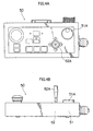
- the control box 50 is provided with a tiltable pulse generating device 52 having a joystick (tilt type lever) 52A.
- a speed (frequency) corresponding to the tilt angle ⁇ of the joystick 52A is assigned in advance, and when the joystick 52A is operated, a voltage corresponding to the tilt angle ⁇ is output.
- the output voltage is converted into a digital signal by an A/D converter 54, and the digital signal is sent to a pulse generating circuit 55.
- the pulse generating circuit 55 has a CPU.
- the CPU selects a setting speed from the signal input to the CPU, and outputs a pulse of a frequency corresponding to the setting speed to the driving pulse input section 64 of the servo amplifier 60.
- the moving table 32 is fed continuously at a speed corresponding to the tilt angle ⁇ of the joystick 52A during the time when the joystick 52A is tilted.
- the servo state is off when the moving table 32 stops. That is to say, when the positioning of the moving table 32 is finished by closed loop control, the servo control is stopped once. At this time, the joystick 52A is operated, and a voltage corresponding to the tilt angle ⁇ is generated, by which the servo state is turned on, and thereby the joystick operation is made enable.
- the servo amplifier 60 is configured as described below.
- the knob 51A of the rotary encoder 51 is turned, the servo state is turned on by a trigger signal telling that encoder pulses are input continuously, and the moving table 32 is fed finely at a speed corresponding to the turning speed of the knob 51 A by the number of pulses corresponding to the turning angle. Subsequently, the servo state is turned off and is returned to the initial state by a trigger signal telling that encoder pulses are not input for a certain period of time.
- the speed control, continuous operation, and step operation of the moving table 32 can be carried out over a wide speed range of 0.03 mm/sec to 100 mm/sec.
- the operator tilts the joystick 52A of the tiltable pulse generating device 52 provided on the control box 50 toward the movement direction.
- a voltage corresponding to the tilt angle ⁇ of the joystick 52A is output, and upon receipt of this voltage output, the servo state of the servo amplifier 60 is turned on.
- This output voltage is converted into a digital signal by the A/D converter 54, and the digital signal is sent to the pulse generating circuit section 55.
- the CPU selects a setting speed based on the input digital signal, and inputs a driving pulse of a frequency corresponding to the setting speed to the driving pulse input section 64 of the servo amplifier 60.
- the input driving pulse is counted up to the deflection counter 61 as needed, and the moving part 16 of the linear motor 12 is excited via the motor drive output section 65 to drive the moving part 16, by which the moving table 32 is moved.
- the movement distance at this time is read in real time by the read head 24 of the linear scale 26, and is input to the scale signal input section 66 of the servo amplifier 60.
- the deflection counter 61 counts deflection of the number of pulses counted up in real time from the scale signal, and the control circuit section 62 controls the driving circuit section 63 so that the deflection counter value is zero.
- the tilt angle ⁇ of the joystick 52A is returned to zero, and the deflection counter value becomes zero, the moving table 32 stops, and the servo state is turned off.
- the moving table 32 can be moved at a speed corresponding to the tilt angle ⁇ during the time when the joystick 52A is tilted.
- the operator turns the knob 51A for the rotary encoder (rotary pulse generating device) 51 provided on the control box 50 in accordance with the movement direction.
- the knob 5 1 A When the knob 5 1 A is turned, a pulse of a frequency corresponding to the turning speed is generated, and is converted into a normal driving pulse by the pulse generating circuit section 55, being input to the servo amplifier 60.
- Fig. 4 shows the control box 50 in the case where the uniaxial drive unit 10 constructed as described above is used for a surface roughness contour measuring apparatus, Fig. 4A being a plan view and Fig. 4B being a front view.
- the rotary encoder 51 serving as the rotary pulse generating device having the knob 51A as well as the tiltable pulse generating device 52 having the joystick 52A.
- a configuration may be used in which the moving table 32 is directly supported on the fixed table 30 so as to be slidable in the uniaxial direction without the use of the linear motion guides 34.
- the driving thrust is varied by the gravity of the moving part 16. Also, when a state in which the moving part 16 is energized is kept to prevent the moving part 16 from dropping in the tilted state, heat is generated in the moving part 16, and a dimensional error of the whole of unit is likely to occur due to the heat. In order to avoid these problems, the configuration as described below can be used.
- the uniaxial drive unit which uses the linear motor 12 having a fixed part 14, which is a rod-shaped magnet in which the N poles and the S poles are arranged alternately in a linear form, and a moving part 16, which is a ring-shaped member having the coil member 40, is fitted on the fixed part 14 and can move linearly along the fixed part 14, the uniaxial drive unit is characterized in that a balance weight is arranged so as to balance with the moving part 16.
- balance weight is defined as "a weight added to eliminate imbalance of a rotating body in grinding, or a weight used for balancing with the gravity of a cross rail of a gantry machine tool or a spindle head of a boring machine” (Dictionary of Cutting, Grinding, and Polishing, compiled by Society of Grinding Engineers, published by Kogyo Chyosakai Publishing Co., Ltd., 1995). In this specification, the term “balance weight” is used in the latter meaning of the above definition.
- the weight of the balance weight be approximately equal to the sum of the weight of the moving part 16 and the weight of the moving table 32.
- balance can be attained by a balance weight having almost the same weight as the gravity of the moving part etc. Therefore, the driving thrust is not varied by the gravity of the moving part etc., and no dimensional accuracy error occurs.
- the weight of the balance weight be in the range of 20% up and down with respect to the sum of the weight of the moving part 16 and the weight of the moving table 32. If the weight of the balance weight is in this range, the variation in the driving thrust due to the gravity of the moving part etc. is often in an allowable range, and a dimensional accuracy error is less liable to occur.
- the balance weight be connected to the moving part 16 by a winding motion transmission member via a winding motion transmission support member provided near one end or both ends of the linear motor 12. If the balance weight is connected to the moving part 16 by the winding motion transmission member via the winding motion transmission support member, balance can be attained easily.
Landscapes
- Engineering & Computer Science (AREA)
- Human Computer Interaction (AREA)
- Manufacturing & Machinery (AREA)
- Physics & Mathematics (AREA)
- General Physics & Mathematics (AREA)
- Automation & Control Theory (AREA)
- Linear Motors (AREA)
- Details Of Measuring And Other Instruments (AREA)
- Eye Examination Apparatus (AREA)
- Control Of Stepping Motors (AREA)
- Sampling And Sample Adjustment (AREA)
- Control Of Linear Motors (AREA)
Abstract
Description
Claims (4)
- A uniaxial drive unit (10) , characterized by comprising:a pulse drive motor (12) having a fixed part (14) and a moving part (16), which is driven by an applied pulse voltage;a fixed table (30); anda moving table (32,34) which is supported so as to be slidable in the uniaxial direction with respect to said fixed table (30), whereinone of said fixed part (14) and moving part (16) is fixed to said fixed table (30), and the other of said fixed part (14) and moving part (16) is fixed to said moving table (32,34),a rotary pulse generating device (50,51,55) having a knob (51A), which is a device for generating an electric pulse for driving said pulse drive motor (12), is provided, said rotary pulse generating device (50,51,55) generating a pulse of a frequency corresponding to the turning speed of said knob (51 A) and generating pulses of the number corresponding to the turning angle of said knob (51 A), andfine feed is provided to said moving table (32,34) by the pulse generated by said rotary pulse generating device (50,51,55).
- The uniaxial drive unit (10) according to claim 1, wherein:said pulse drive motor (12) is a linear motor (12) comprising:a fixed part (14) which is a rod-shaped magnet in which the N poles and the S poles are arranged alternately; anda moving part (16) having a coil member (40), which is fitted on said fixed part (14) and can move along said fixed part (14).
- The uniaxial drive unit (10) according to claim 1, wherein:a tiltable pulse generating device (50,52,54,55) having a tiltable lever (52A), which is a device for generating an electric pulse for driving said pulse drive motor (12), is provided, said tiltable pulse generating device (50,52,54,55) generating a continuous pulse of a frequency corresponding to the tilt angle of said tiltable lever (52A), andsaid moving table (32,34) is moved continuously by the continuous pulse generated by said tiltable pulse generating device (50,52,54,55).
- The uniaxial drive unit (10) according to claim 3, wherein:a scale (24,26) for detecting the position of said moving table (32) and a servo amplifier (60) for feedback controlling said pulse drive motor (12) by a signal sent from said scale (24,26) are provided, andwhen said moving table (32,34) is stopped, the servo state of said servo amplifier (60) is turned off, and when the operation of said tiltable pulse generating device (50,52,54,55) or rotary pulse generating device (50,51,55) is detected, the servo state of said servo amplifier (60) is turned on.
Applications Claiming Priority (2)
| Application Number | Priority Date | Filing Date | Title |
|---|---|---|---|
| JP2003085598 | 2003-03-26 | ||
| JP2003085598A JP2004297884A (en) | 2003-03-26 | 2003-03-26 | Single shaft drive device |
Publications (2)
| Publication Number | Publication Date |
|---|---|
| EP1462893A2 true EP1462893A2 (en) | 2004-09-29 |
| EP1462893A3 EP1462893A3 (en) | 2008-03-05 |
Family
ID=32821501
Family Applications (1)
| Application Number | Title | Priority Date | Filing Date |
|---|---|---|---|
| EP04007114A Withdrawn EP1462893A3 (en) | 2003-03-26 | 2004-03-24 | Uniaxial drive unit |
Country Status (3)
| Country | Link |
|---|---|
| US (1) | US7071583B2 (en) |
| EP (1) | EP1462893A3 (en) |
| JP (1) | JP2004297884A (en) |
Families Citing this family (3)
| Publication number | Priority date | Publication date | Assignee | Title |
|---|---|---|---|---|
| EP1806829B1 (en) * | 2004-09-30 | 2019-12-18 | Thk Co., Ltd. | Rod-type linear motor |
| KR20200042660A (en) * | 2018-10-16 | 2020-04-24 | 현대자동차주식회사 | Apparatus for controlling display of vehicle, system having the same and method thereof |
| CN110620534B (en) * | 2019-10-15 | 2020-11-20 | 烟台大学 | Nonlinear Softening and Variable Structure Sliding Mode Control of Permanent Magnet Synchronous Motors for Speed Stabilization |
Family Cites Families (13)
| Publication number | Priority date | Publication date | Assignee | Title |
|---|---|---|---|---|
| US4379245A (en) * | 1980-03-20 | 1983-04-05 | Dynascan Corporation | Manually operable rotary pulse generating apparatus for pulse counting and similar applications |
| JPS59175390A (en) * | 1983-03-25 | 1984-10-04 | Fujitsu Ltd | Positioning control circuit of dc motor |
| US4695137A (en) * | 1986-02-26 | 1987-09-22 | Carl-Zeiss-Stiftung, Heidenheim/Brenz | Motorized focus drive for a microscope |
| US5210636A (en) * | 1991-07-19 | 1993-05-11 | Baer Stephen C | Rotational oscillatory optical scanning device |
| DE4231379C2 (en) * | 1992-09-19 | 2001-09-13 | Leica Microsystems | Microscope with a multifunctional drive button |
| FR2696115B1 (en) * | 1992-09-25 | 1994-12-16 | Somab | Improvements to a tool lathe provided with electronic-assisted control means. |
| US5439328A (en) * | 1993-08-24 | 1995-08-08 | E. I. Du Pont De Nemours And Company | Single-head drill with video attachment |
| US5677709A (en) * | 1994-02-15 | 1997-10-14 | Shimadzu Corporation | Micromanipulator system with multi-direction control joy stick and precision control means |
| JP3453991B2 (en) * | 1995-03-31 | 2003-10-06 | ミノルタ株式会社 | Linear motor |
| US6008552A (en) * | 1996-12-30 | 1999-12-28 | Minolta Co., Ltd. | Linear drive device |
| JPH11150973A (en) | 1997-11-14 | 1999-06-02 | Minolta Co Ltd | Linear motor |
| DE19809382C2 (en) * | 1997-03-14 | 2003-06-26 | Dango & Dienenthal Maschbau | Control system for handling machines |
| US6865425B2 (en) * | 2002-01-07 | 2005-03-08 | Siemens Energy & Automation, Inc. | State machine for a pulse output function |
-
2003
- 2003-03-26 JP JP2003085598A patent/JP2004297884A/en active Pending
-
2004
- 2004-03-24 EP EP04007114A patent/EP1462893A3/en not_active Withdrawn
- 2004-03-24 US US10/807,134 patent/US7071583B2/en not_active Expired - Fee Related
Also Published As
| Publication number | Publication date |
|---|---|
| US20040189234A1 (en) | 2004-09-30 |
| JP2004297884A (en) | 2004-10-21 |
| US7071583B2 (en) | 2006-07-04 |
| EP1462893A3 (en) | 2008-03-05 |
Similar Documents
| Publication | Publication Date | Title |
|---|---|---|
| EP1463185B1 (en) | Uniaxial drive unit and surface shape measuring apparatus using the same | |
| JP5443718B2 (en) | Linear motor system and control device | |
| JP5639934B2 (en) | Surface texture measuring machine | |
| JP4094799B2 (en) | Slide device with built-in movable magnet type linear motor | |
| EP1306833B1 (en) | Voice coil driven positioner for coarse and fine positioning of magnetic head in multi track tape drive | |
| JP4258790B2 (en) | Driving device for moving the platform in one plane | |
| US6495935B1 (en) | Linear motor drive unit | |
| JP5848873B2 (en) | Control device and measuring device | |
| JP2004072960A (en) | Alignment stage device with built-in linear motor | |
| US8008815B2 (en) | Planar stage moving apparatus for machine | |
| US7071583B2 (en) | Uniaxial drive unit | |
| US6888289B2 (en) | Multi-axes, sub-micron positioner | |
| Shinno et al. | High speed nanometer positioning using a hybrid linear motor | |
| US6591757B1 (en) | Motor driven high stability brake for linear motion systems | |
| JP2004129441A (en) | Single-shaft driver | |
| JP2001261234A (en) | Traversing device and traversing method | |
| EP0921456B1 (en) | Control processes for linear voice coil actuator | |
| JPH0212707B2 (en) | ||
| JP2002355730A (en) | Table positioning device | |
| KR100699346B1 (en) | Non-contact rotary stage | |
| JP2970802B2 (en) | XY stage device | |
| KR20250162250A (en) | Scaleless linear motor system and control method thereof | |
| KR20040015837A (en) | rectangular coordinates robot | |
| JPH06343287A (en) | Driving device for precision mechanical equipment | |
| JPH0764000A (en) | Optical switch |
Legal Events
| Date | Code | Title | Description |
|---|---|---|---|
| PUAI | Public reference made under article 153(3) epc to a published international application that has entered the european phase |
Free format text: ORIGINAL CODE: 0009012 |
|
| AK | Designated contracting states |
Kind code of ref document: A2 Designated state(s): AT BE BG CH CY CZ DE DK EE ES FI FR GB GR HU IE IT LI LU MC NL PL PT RO SE SI SK TR |
|
| AX | Request for extension of the european patent |
Extension state: AL LT LV MK |
|
| PUAL | Search report despatched |
Free format text: ORIGINAL CODE: 0009013 |
|
| AK | Designated contracting states |
Kind code of ref document: A3 Designated state(s): AT BE BG CH CY CZ DE DK EE ES FI FR GB GR HU IE IT LI LU MC NL PL PT RO SE SI SK TR |
|
| AX | Request for extension of the european patent |
Extension state: AL LT LV MK |
|
| RIC1 | Information provided on ipc code assigned before grant |
Ipc: G05B 19/23 20060101ALI20080131BHEP Ipc: G05B 19/409 20060101AFI20080131BHEP |
|
| AKX | Designation fees paid | ||
| STAA | Information on the status of an ep patent application or granted ep patent |
Free format text: STATUS: THE APPLICATION IS DEEMED TO BE WITHDRAWN |
|
| 18D | Application deemed to be withdrawn |
Effective date: 20080806 |
|
| REG | Reference to a national code |
Ref country code: DE Ref legal event code: 8566 |